EP3964774B1 - Appliance being a refrigerator or a freezer with a drainage assembly - Google Patents
Appliance being a refrigerator or a freezer with a drainage assembly Download PDFInfo
- Publication number
- EP3964774B1 EP3964774B1 EP21190006.3A EP21190006A EP3964774B1 EP 3964774 B1 EP3964774 B1 EP 3964774B1 EP 21190006 A EP21190006 A EP 21190006A EP 3964774 B1 EP3964774 B1 EP 3964774B1
- Authority
- EP
- European Patent Office
- Prior art keywords
- appliance
- drainage tube
- flexible body
- drainage
- flanges
- Prior art date
- Legal status (The legal status is an assumption and is not a legal conclusion. Google has not performed a legal analysis and makes no representation as to the accuracy of the status listed.)
- Active
Links
Images







Classifications
-
- F—MECHANICAL ENGINEERING; LIGHTING; HEATING; WEAPONS; BLASTING
- F25—REFRIGERATION OR COOLING; COMBINED HEATING AND REFRIGERATION SYSTEMS; HEAT PUMP SYSTEMS; MANUFACTURE OR STORAGE OF ICE; LIQUEFACTION SOLIDIFICATION OF GASES
- F25D—REFRIGERATORS; COLD ROOMS; ICE-BOXES; COOLING OR FREEZING APPARATUS NOT OTHERWISE PROVIDED FOR
- F25D21/00—Defrosting; Preventing frosting; Removing condensed or defrost water
- F25D21/14—Collecting or removing condensed and defrost water; Drip trays
-
- F—MECHANICAL ENGINEERING; LIGHTING; HEATING; WEAPONS; BLASTING
- F25—REFRIGERATION OR COOLING; COMBINED HEATING AND REFRIGERATION SYSTEMS; HEAT PUMP SYSTEMS; MANUFACTURE OR STORAGE OF ICE; LIQUEFACTION SOLIDIFICATION OF GASES
- F25D—REFRIGERATORS; COLD ROOMS; ICE-BOXES; COOLING OR FREEZING APPARATUS NOT OTHERWISE PROVIDED FOR
- F25D23/00—General constructional features
-
- F—MECHANICAL ENGINEERING; LIGHTING; HEATING; WEAPONS; BLASTING
- F25—REFRIGERATION OR COOLING; COMBINED HEATING AND REFRIGERATION SYSTEMS; HEAT PUMP SYSTEMS; MANUFACTURE OR STORAGE OF ICE; LIQUEFACTION SOLIDIFICATION OF GASES
- F25D—REFRIGERATORS; COLD ROOMS; ICE-BOXES; COOLING OR FREEZING APPARATUS NOT OTHERWISE PROVIDED FOR
- F25D23/00—General constructional features
- F25D23/06—Walls
- F25D23/061—Walls with conduit means
-
- F—MECHANICAL ENGINEERING; LIGHTING; HEATING; WEAPONS; BLASTING
- F25—REFRIGERATION OR COOLING; COMBINED HEATING AND REFRIGERATION SYSTEMS; HEAT PUMP SYSTEMS; MANUFACTURE OR STORAGE OF ICE; LIQUEFACTION SOLIDIFICATION OF GASES
- F25D—REFRIGERATORS; COLD ROOMS; ICE-BOXES; COOLING OR FREEZING APPARATUS NOT OTHERWISE PROVIDED FOR
- F25D23/00—General constructional features
- F25D23/06—Walls
- F25D23/065—Details
- F25D23/066—Liners
-
- F—MECHANICAL ENGINEERING; LIGHTING; HEATING; WEAPONS; BLASTING
- F25—REFRIGERATION OR COOLING; COMBINED HEATING AND REFRIGERATION SYSTEMS; HEAT PUMP SYSTEMS; MANUFACTURE OR STORAGE OF ICE; LIQUEFACTION SOLIDIFICATION OF GASES
- F25D—REFRIGERATORS; COLD ROOMS; ICE-BOXES; COOLING OR FREEZING APPARATUS NOT OTHERWISE PROVIDED FOR
- F25D23/00—General constructional features
- F25D23/06—Walls
- F25D23/065—Details
- F25D23/068—Arrangements for circulating fluids through the insulating material
-
- F—MECHANICAL ENGINEERING; LIGHTING; HEATING; WEAPONS; BLASTING
- F25—REFRIGERATION OR COOLING; COMBINED HEATING AND REFRIGERATION SYSTEMS; HEAT PUMP SYSTEMS; MANUFACTURE OR STORAGE OF ICE; LIQUEFACTION SOLIDIFICATION OF GASES
- F25D—REFRIGERATORS; COLD ROOMS; ICE-BOXES; COOLING OR FREEZING APPARATUS NOT OTHERWISE PROVIDED FOR
- F25D2201/00—Insulation
- F25D2201/10—Insulation with respect to heat
- F25D2201/14—Insulation with respect to heat using subatmospheric pressure
-
- F—MECHANICAL ENGINEERING; LIGHTING; HEATING; WEAPONS; BLASTING
- F25—REFRIGERATION OR COOLING; COMBINED HEATING AND REFRIGERATION SYSTEMS; HEAT PUMP SYSTEMS; MANUFACTURE OR STORAGE OF ICE; LIQUEFACTION SOLIDIFICATION OF GASES
- F25D—REFRIGERATORS; COLD ROOMS; ICE-BOXES; COOLING OR FREEZING APPARATUS NOT OTHERWISE PROVIDED FOR
- F25D23/00—General constructional features
- F25D23/08—Parts formed wholly or mainly of plastics materials
-
- F—MECHANICAL ENGINEERING; LIGHTING; HEATING; WEAPONS; BLASTING
- F25—REFRIGERATION OR COOLING; COMBINED HEATING AND REFRIGERATION SYSTEMS; HEAT PUMP SYSTEMS; MANUFACTURE OR STORAGE OF ICE; LIQUEFACTION SOLIDIFICATION OF GASES
- F25D—REFRIGERATORS; COLD ROOMS; ICE-BOXES; COOLING OR FREEZING APPARATUS NOT OTHERWISE PROVIDED FOR
- F25D2321/00—Details or arrangements for defrosting; Preventing frosting; Removing condensed or defrost water, not provided for in other groups of this subclass
- F25D2321/14—Collecting condense or defrost water; Removing condense or defrost water
- F25D2321/142—Collecting condense or defrost water; Removing condense or defrost water characterised by droplet guides
-
- F—MECHANICAL ENGINEERING; LIGHTING; HEATING; WEAPONS; BLASTING
- F25—REFRIGERATION OR COOLING; COMBINED HEATING AND REFRIGERATION SYSTEMS; HEAT PUMP SYSTEMS; MANUFACTURE OR STORAGE OF ICE; LIQUEFACTION SOLIDIFICATION OF GASES
- F25D—REFRIGERATORS; COLD ROOMS; ICE-BOXES; COOLING OR FREEZING APPARATUS NOT OTHERWISE PROVIDED FOR
- F25D2321/00—Details or arrangements for defrosting; Preventing frosting; Removing condensed or defrost water, not provided for in other groups of this subclass
- F25D2321/14—Collecting condense or defrost water; Removing condense or defrost water
- F25D2321/143—Collecting condense or defrost water; Removing condense or defrost water characterised by means to fix, clamp, or connect water pipes or evaporation trays
-
- F—MECHANICAL ENGINEERING; LIGHTING; HEATING; WEAPONS; BLASTING
- F25—REFRIGERATION OR COOLING; COMBINED HEATING AND REFRIGERATION SYSTEMS; HEAT PUMP SYSTEMS; MANUFACTURE OR STORAGE OF ICE; LIQUEFACTION SOLIDIFICATION OF GASES
- F25D—REFRIGERATORS; COLD ROOMS; ICE-BOXES; COOLING OR FREEZING APPARATUS NOT OTHERWISE PROVIDED FOR
- F25D2321/00—Details or arrangements for defrosting; Preventing frosting; Removing condensed or defrost water, not provided for in other groups of this subclass
- F25D2321/14—Collecting condense or defrost water; Removing condense or defrost water
- F25D2321/146—Collecting condense or defrost water; Removing condense or defrost water characterised by the pipes or pipe connections
Definitions
- the present disclosure relates to an appliance including an insulated structure and a drainage assembly, the appliance being a refrigerator or a freezer.
- Document US4,843,835 discloses a refrigerator drain apparatus adapted for being connected between an aperture in the liner and a hole in the outer casing before foaming-in-place and subsequently providing a passageway through the insulation for draining defrost water.
- the refrigerator drain apparatus comprises a rigid plastic conduit, means for twist-locking the conduit to the aperture in the Liner, means for sealing the conduit to the liner for preventing insulation foam under pressure from Leaking through the aperture in the liner and means for sealing the conduit to the outer casing for preventing insulation foam under pressure from Leaking through the hole in the outer casing.
- Document US2020/025436A1 discloses a pipe assembly operable to be installed in a refrigerator.
- the pipe assembly comprises a first pipe extending from an evaporator of the refrigerator and inclined downward to drain water and a second pipe connected to a downstream end of the first pipe and operable to receive water.
- the first pipe comprises a connection portion fastened to the second pipe and a water guide portion extending further downward from the connection portion.
- the second pipe extends from the first pipe and is inclined downward at a steeper slope than a slope of the first pipe.
- Document EP2476981A2 discloses a refrigerator having a drain hose assembly.
- the refrigerator includes an upper hose, a Lower hose connected to the upper hose while being arranged in a machinery chamber, the Lower hose being provided with an air inlet hole to introduce outside air, and an opening and closing unit provided at the Lower hose to be upwardly pivoted by negative pressure in a storage chamber and to be downwardly pivoted by gravity, in order to open and close the air inlet hole, respectively.
- Further relevant prior art document is US2020/191466A1 .
- the terms “upper,” “lower,” “right,” “left,” “rear,” “front,” “vertical,” “horizontal,” and derivatives thereof shall relate to the disclosure as oriented in FIG. 1 .
- the term “front” shall refer to the surface of the element closer to an intended viewer, and the term “rear” shall refer to the surface of the element further from the intended viewer.
- the disclosure may assume various alternative orientations, except where expressly specified to the contrary.
- the specific devices and processes illustrated in the attached drawings, and described in the following specification are simply exemplary embodiments of the inventive concepts defined in the appended claims. Hence, specific dimensions and other physical characteristics relating to the embodiments disclosed herein are not to be considered as limiting, unless the claims expressly state otherwise.
- reference numeral 10 generally designates a drainage assembly for an insulated structure 12 included in an appliance 36 according to claim 1.
- the drainage assembly 10 includes a flexible body 14 that has a plurality of flexures 16 and defines an opening 18.
- the flexible body 14 also defines notches 20 that extend radially from the opening 18.
- a first drainage tube 22 extends through the opening 18 and has receiving flanges 24 disposed within the notches 20 defined by the flexible body 14.
- a second drainage tube 26 is in fluid communication with the first drainage tube 22.
- the second drainage tube 26 has engagement flanges 28 that are disposed within the receiving flanges 24 of the first drainage tube 22.
- first drainage tube 22 may also be referred to as an outlet tube 22
- second drainage tube 26 may be referred to as an inlet tube 26.
- Both the outlet tube 22 and the inlet tube 26 each include a first end 30 and a second end 32, described further below.
- the drainage assembly 10 is a part of an appliance 36 illustrated as a refrigerator. It is also contemplated that the appliance 36 may be a freezer that may utilize the drainage assembly 10 to redirect liquid that has been defrosted or may otherwise be drained from the appliance 36.
- the appliance 36 includes a liner 38 and a wrapper 40 to form the insulated structure 12. It is contemplated that negative pressure is maintained within the insulated structure 12 between the liner 38 and the wrapper 40, such that the insulated structure 12 is a vacuum insulated structure.
- the liner 38 defines a first aperture 42
- the wrapper 40 defines a second aperture 44 that generally corresponds with and is complementary to the first aperture 42.
- the drainage assembly 10 is positioned between and coupled to each of the liner 38 and the wrapper 40, such that the drainage assembly 10 seals the first and second apertures 42, 44 of the liner 38 and the wrapper 40, respectively. Additionally or alternatively, the liner 38 and the wrapper 40 may each define multiple apertures, such that multiple drainage assemblies 10 may be positioned between the wrapper 40 and the liner 38 in respective apertures.
- the illustrated appliance 36 is a refrigerator appliance. It is generally contemplated that the appliance 36 may include a freezer compartment 46 along with a refrigeration compartment 47, which typically are configured with heaters to provide sufficient heating capacity to minimize frost build-up in the freezer and refrigeration compartments 46, 47. As the freezer compartment 46 and/or the refrigeration compartment 47 is defrosted, the liquid is directed toward the drainage assembly 10 to remove the liquid from the appliance 36, as described in further detail below. It is generally contemplated that an external drainage line 48 is coupled to the outlet tube 22.
- the flexible body 14 is generally formed to fit the general shape of the first and second apertures 42, 44.
- the flexible body 14 includes the plurality of flexures 16 such that the flexible body 14 is formed from a flexible elastomeric and/or polymeric material to bend to fit within the first and second apertures 42, 44 of the liner 38 and the wrapper 40, respectively.
- the plurality of flexures 16 generally defines a corrugated pattern, such that the flexible body 14, as depicted, includes flexures 50 and corresponding depressions 52 defined between a first surface 54 and a second surface 56 of the flexible body 14.
- the flexures 50 and depressions 52 generally facilitate compression and bending of the flexible body 14 in order to be positioned within the first and second apertures 42, 44 of the liner 38 and the wrapper 40, respectively.
- the flexible body 14 may generally have an elliptical shape.
- the flexible body 14 is positioned within the first and second apertures 42, 44 of the liner 38 and the wrapper 40, each of which have a generally elliptical configuration.
- the flexible body 14 and the first and second apertures 42, 44 may have other configurations such as circular, square, triangular, and other shapes known in the art.
- the flexible body 14 also defines a pass-through opening 58 and a housing 60 through which a suction line and other refrigeration components of the appliance 36 may pass.
- the housing 60 may be formed from a polymeric material, such as plastic, and may be generally insulated to potential suction line heat exchangers that may pass through the housing 60 and the pass-through opening 58.
- the pass-through opening 58 and the housing 60 are generally adjacent to the opening 18 in which the outlet tube 22 may be positioned, described further below.
- the flexible body 14 defines the opening 18 and notches 20 that radially extend from the opening 18.
- the opening 18 and the notches 20 are generally defined at an angle within the flexible body 14, such that the notches 20 may have varying depth relative to the first surface 54 of the flexible body 14.
- the notches 20 may include a first notch 62, a second notch 64, and a third notch 66.
- the first and third notches 62, 66 may be proximate to the pass-through opening 58 and may have a greater depth than the second notch 64, as described in more detail below in reference to the outlet tube 22.
- Each of the notches 20 may be generally defined by a ledge 68 and surrounding sidewalls 70.
- each of the sidewalls 70 for each respective notch 20 may have a varied height to define the varied depth of each of the notches 20 mentioned above.
- the flexible body 14 defines at least one notch 20 extending from the opening 18, as illustrated in FIG. 9 and described in more detail below.
- the notches 20 are generally defined on the first surface 54 of the flexible body 14.
- a projection 72 ( FIG. 13 ) is defined on the second surface 56, described in more detail below.
- a pull-tab 74 ( FIG. 13 ) is defined on the second surface 56 of the flexible body 14. It is generally contemplated that the pull-tab 74 ( FIG. 13 ) may be utilized for repositioning or removing the flexible body 14 from the liner 38 and the wrapper 40. It is further contemplated that there may be more than one pull-tab 74 ( FIG. 13 ), such that a user may utilize either pull-tab 74 ( FIG. 13 ) to manipulate the flexible body 14 .
- the flexible body 14 defines a recess 76 ( FIG. 13 ) proximate to the projection 72.
- the outlet tube 22 includes the receiving flanges 24 outwardly extending from a tube body 80 that defines a channel 82 therethrough.
- the receiving flanges 24 each have an open entry portion 84, a closed base 86, and a cavity 88 defined between the open entry portion 84 and the closed base 86.
- the receiving flanges 24 may include a first receiving flange 90, a second receiving flange 92, and a third receiving flange 94.
- each receiving flange 24 is disposed on the ledge 68 of the respective notch 20 of the flexible body 14.
- the first receiving flange 90 is disposed on the ledge 68 of the first notch 62, such that the depth of the first receiving flange 90 generally corresponds with the depth of the first notch 62.
- the receiving flanges 24 are defined on the first end 30 of the tube body 80 and attachment rings 96 are defined on the second end 32 of the tube body 80.
- the first receiving flange 90 may be disposed approximately 180-degrees from the second receiving flange 92 about the first end 30 of the outlet tube 22.
- the inlet tube 26 includes an attachment base 100 defining a collecting cavity 102, a tube body 104 defining a drainage channel 108, and the engagement flanges 28 outwardly extending from the tube body 104.
- the engagement flanges 28 may include a first engagement flange 110, a second engagement flange 112, and a third engagement flange 114, described below.
- the attachment base 100 is generally planar and defines the collecting cavity 102 from which the tube body 104 extends.
- the attachment base 100 may also have attachment tabs 116 outwardly extending from a planar surface 118 of the attachment base 100.
- the attachment tabs 116 of the attachment base 100 are configured to couple the attachment base 100 to the freezer compartment 46 ( FIG. 1 ) and/or the refrigeration compartment 47 of the appliance 36 ( FIG. 1 ).
- the inlet tube 26 is operably coupled to the outlet tube 22 and is configured to direct the drained liquid from the appliance 36 ( FIG. 1 ) via the external drainage line 48 ( FIG. 2 ).
- the inlet tube 26 is positioned within the first end 30 of the outlet tube 22, and the external drainage line 48 ( FIG. 2 ) may be coupled to the attachment rings 96 of the outlet tube 22.
- the external drainage line 48 ( FIG. 2 ) generally removes drained liquid from the appliance 36 ( FIG. 2 ) via the drainage assembly 10.
- the inlet tube 26 is coupled to the freezer compartment 46 ( FIG. 1 ) and/or the refrigeration compartment 47 ( FIG. 1 ) via the attachment tabs 116 and collects the liquid within the collecting cavity 102.
- the liquid is passed through the drainage channel 108 of the inlet tube 26 to the outlet tube 22 and out of the appliance 36 through the external drainage line 48.
- the receiving flanges 24 of the outlet tube 22 are disposed within the notches 20 of the flexible body 14 to define an interlocking arrangement.
- the outlet tube 22 is fixedly disposed within the flexible body 14, such that the receiving flanges 24 are retained by the sidewalls 70 of the notches 20.
- the receiving flanges 24 may engage the sidewalls 70 of the notches 20 of the flexible body 14, and the receiving flanges 24 may engage the ledges 68 of each notch 20 upon any potential rearward movement of the outlet tube 22.
- the inlet tube 26 may be positioned within and coupled to the outlet tube 22.
- the tube body 104 of the inlet tube 26 may be smaller than the tube body 80 of the outlet tube 22, such that the tube body 104 of the inlet tube 26 may be disposed within the tube body 80 of the outlet tube 22.
- the engagement flanges 28 of the inlet tube 26 are configured to be disposed within the receiving flanges 24 of the outlet tube 22 via the respective open entry portions 84.
- Each engagement flange 28 may engage the closed base 86 of each of the receiving flanges 24.
- each engagement flange 28 may generally abut the respective closed base 86 of the outlet tube 22, such that the engagement flanges 28 may be completely and/or partially disposed within the receiving flanges 24.
- the second and third engagement flanges 112, 114 partially extend from the second and third receiving flanges 92, 94. Additionally or alternatively, the engagement flanges 28 may be fully disposed within the respective receiving flanges 24. The arrangement of the engagement flanges 28 within the receiving flanges 24 may generally be related to the angled connection between the inlet tube 26 and the outlet tube 22.
- an interlocking arrangement of the inlet and outlet tubes 26, 22 may be defined by the positioning of each engagement flange 28 within the respective cavity 88 defined by each of the receiving flanges 24.
- the inlet tube 26 is coupled to the freezer compartment 46 ( FIG. 1 ), which ultimately stabilizes the outlet tube 22 as the outlet tube 22 is coupled to the inlet tube 26.
- the interlocking arrangement between the inlet tube 26 and the outlet tube 22 stabilizes the flexible body 14 within the first and second apertures 42, 44 as the engagement flanges 28 are fixedly coupled to the receiving flanges 24, which are fixedly coupled to the flexible body 14.
- the interlocking arrangements minimize potential rotation of the flexible body 14 within the first and second apertures 42, 44 ( FIG. 2 ) of the liner 38 ( FIG. 2 ) and the wrapper 40 ( FIG. 2 ).
- the drainage assembly 10 includes a single drainage tube 130, the flexible body 14, and a locking feature 132.
- the flexible body 14 defines a notch 20 proximate to the opening 18.
- the illustrated notch 20 is generally arcuate in shape; however, it is also contemplated that the notch 20 may be rectangular, square, circular, or any other shape generally regarded within the art.
- the drainage tube 130 includes a retention flange 134 extending from a tube body 136.
- the drainage tube 130 may also define locking projections 138 and an abutment member 140 extending from the tube body 136 and configured to engage the locking feature 132, as described in more detail below.
- the drainage tube 130 may have the attachment rings 96, mentioned above, extending around the second end 32 of the tube body 136, such that the external drainage line 48 ( FIG. 2 ) may be coupled to the drainage tube 130 via the attachment rings 96.
- the drainage tube 130 includes the attachment base 100 to couple the drainage tube 130 to the appliance 36 ( FIG. 1 ) and generally directs liquid from the appliance 36 ( FIG. 1 ) through the drainage tube 130.
- the attachment base 100 is depicted as being generally concave, such that the liquid may be collected and directed to the drainage channel 108 defined by the attachment base 100 and the tube body 136.
- the drainage tube 130 is illustrated as having a generally rectilinear shape and may include a bracing member 142 to provide structural support for the drainage tube 130. It is also contemplated that the drainage tube 130 may have alternate shapes and configurations, such as the generally linear shape of the first drainage tube 22 ( FIG. 3 ) and the generally angular shape of the second drainage tube 26 ( FIG. 3 ), described above.
- the locking feature 132 is operably coupled to the flexible body 14 and selectively coupled to the drainage tube 130.
- the locking feature 132 is disposed in the recess 76 defined by the flexible body 14.
- the locking feature 132 includes inclined edges 144 defining spaces 146 therebetween and a clip 148.
- the clip 148 may have tabs 150, described in more detail below.
- the locking feature 132 defines a central void 152 through which the drainage tube 130 extends.
- the locking feature 132 also has a face 154 defined by the angled extension of the inclined edges 144, such that the inclined edges 144 outwardly extend from the face 154 of the locking feature 132.
- the locking feature 132 is rotatable within the recess 76 of the flexible body 14, such that the locking feature 132 rotates about the drainage tube 130 between a first position 156 and a second position 158. Stated differently, the locking feature 132 is rotatable between a first, locked position 156 and a second, unlocked position 158.
- the locking feature 132 may be positioned around the second end 32 of the drainage tube 130 in the unlocked position 158, such that the locking projections 138 of the drainage tube 130 are positioned within the spaces 146 defined between each of the inclined edges 144 of the locking feature 132.
- the locking feature 132 may be selectively removed from or disposed on the flexible body 14 in the unlocked position 158.
- the inclined edges 144 of the locking feature 132 are at least partially raised relative to the face 154 of the locking feature 132, such that the inclined edges 144 may partially extend from the face 154 of the locking feature 132. It is generally contemplated that the inclined edges 144 may define an acute angle between an engagement surface 160 of the inclined edges 144 and the face 154 of the locking feature 132.
- the inclined edges 144 of the locking feature 132 selectively engage the locking projections 138 defined by the drainage tube 130 in the locked position 156, such that the locking projections 138 translate along the engagement surfaces 160 of each inclined edge 144.
- the gradual incline of the inclined edges 144 facilitates the rotation of the locking feature 132 between the locked position 156 and the unlocked position 158 relative to the drainage tube 130, such that as the locking feature 132 rotates about the drainage tube 130 the locking projections 138 of the drainage tube 130 engage the engagement surface 160 of each inclined edge 144.
- the drainage tube 130 may include the abutment member 140 that may abut at least one of the inclined edges 144 in the locked position 156 of the locking feature 132.
- the abutment member 140 may minimize the potential strain that may result from the locking feature 132 being rotated into the locked position 156. Specifically, the abutment member 140 minimizes the potential for the locking projections 138 of the drainage tube 130 to be altered under the rotational pressure of the locking feature 132.
- the rotation of the locking feature 132 is further controlled via the clip 148 selectively coupling to the projection 72 defined on the flexible body 14.
- the tabs 150 of the clip 148 are generally flexible, such that the tabs 150 may flex apart and snap back into place as the clip 148 is positioned around the projection 72.
- the clip 148 retains the locking feature 132 in place to fixedly couple the drainage tube 130 to the flexible body 14.
- the coupling of the clip 148 to the projection 72 minimizes potential rotation of the locking feature 132 from the locked position 156 to the unlocked position 158.
- the clip 148 and the locking feature 132 may fixedly couple the drainage tube 130 to the flexible body 14.
- the drainage assembly 10 generally provides a secure drainage system for the appliance 36, such that the flexible body 14 is easily positioned and adjusted within the insulated structure 12.
- the attachment of either the first and second drainage tubes 22, 26, or the single drainage tube 130 guides the positioning of the flexible body 14 within the insulated structure 12 as a result of the notches 20 guiding the assembly of the drainage assembly 10. Further, potential rotation of the flexible body 14 is minimized as a result of the attachment with the drainage tube 130 or the first and second drainage tubes 22, 26, as each is coupled to the appliance 36 and fixedly coupled to the flexible body 14.
Landscapes
- Engineering & Computer Science (AREA)
- Chemical & Material Sciences (AREA)
- Combustion & Propulsion (AREA)
- Physics & Mathematics (AREA)
- Mechanical Engineering (AREA)
- Thermal Sciences (AREA)
- General Engineering & Computer Science (AREA)
- Rigid Pipes And Flexible Pipes (AREA)
- Installation Of Indoor Wiring (AREA)
Description
- The present disclosure relates to an appliance including an insulated structure and a drainage assembly, the appliance being a refrigerator or a freezer.
- Document
US4,843,835 discloses a refrigerator drain apparatus adapted for being connected between an aperture in the liner and a hole in the outer casing before foaming-in-place and subsequently providing a passageway through the insulation for draining defrost water. The refrigerator drain apparatus comprises a rigid plastic conduit, means for twist-locking the conduit to the aperture in the Liner, means for sealing the conduit to the liner for preventing insulation foam under pressure from Leaking through the aperture in the liner and means for sealing the conduit to the outer casing for preventing insulation foam under pressure from Leaking through the hole in the outer casing. - Document
US2020/025436A1 discloses a pipe assembly operable to be installed in a refrigerator. The pipe assembly comprises a first pipe extending from an evaporator of the refrigerator and inclined downward to drain water and a second pipe connected to a downstream end of the first pipe and operable to receive water. The first pipe comprises a connection portion fastened to the second pipe and a water guide portion extending further downward from the connection portion. The second pipe extends from the first pipe and is inclined downward at a steeper slope than a slope of the first pipe. - Document
EP2476981A2 discloses a refrigerator having a drain hose assembly. The refrigerator includes an upper hose, a Lower hose connected to the upper hose while being arranged in a machinery chamber, the Lower hose being provided with an air inlet hole to introduce outside air, and an opening and closing unit provided at the Lower hose to be upwardly pivoted by negative pressure in a storage chamber and to be downwardly pivoted by gravity, in order to open and close the air inlet hole, respectively. Further relevant prior art document isUS2020/191466A1 . - The present invention is disclosed in the independent claim 1. Further embodiments are disclosed in the dependent claims.
- In the drawings:
-
FIG. 1 is a rear top perspective view of an appliance of the present invention. -
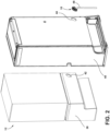
FIG. 2 is an exploded rear top perspective view of an insulated structure including a drainage assembly of the present invention. -
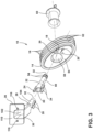
FIG. 3 is an exploded top perspective view of a drainage assembly of the present invention. -
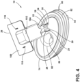
FIG. 4 is a top perspective view of the drainage assembly ofFIG. 3 with an inlet tube coupled to a flexible body of the drainage assembly; -
FIG. 5 is a top elevational view of a flexible body of the present invention that defines notches extending radially from an opening defined by the flexible body; -
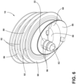
FIG. 6 is a bottom perspective view of a drainage assembly of the present invention. -
FIG. 7 is a top perspective view of an outlet tube of a drainage assembly of the present invention. -
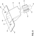
FIG. 8 is a top perspective view of an inlet tube of a drainage assembly of the present invention. -
FIG. 9 is an exploded top perspective view of a drainage assembly of the present invention. -
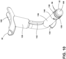
FIG. 10 is a top perspective view of a drainage tube of the present invention. -
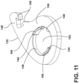
FIG. 11 is a top perspective view of a locking feature of the present invention. -
FIG. 12 is a top perspective view of a drainage assembly of the present invention. -
FIG. 13 is a top rear perspective view of the drainage assembly ofFIG. 12 with a locking feature in a first position; -
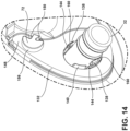
FIG. 14 is an enlarged view of the locking feature of FI. 13 taken at area XIV; and -
FIG. 15 is a top rear perspective view of the drainage assembly ofFIG. 13 with the locking feature in a second position. - The components in the figures are not necessarily to scale, emphasis instead being placed upon illustrating the principles described herein.
- The present illustrated embodiments reside primarily in combinations of apparatus components related to a drainage assembly. Accordingly, the apparatus components have been represented, where appropriate, by conventional symbols in the drawings, showing only those specific details that are pertinent to understanding the embodiments of the present disclosure so as not to obscure the disclosure with details that will be readily apparent to those of ordinary skill in the art having the benefit of the description herein. Further, like numerals in the description and drawings represent like elements.
- For purposes of description herein, the terms "upper," "lower," "right," "left," "rear," "front," "vertical," "horizontal," and derivatives thereof shall relate to the disclosure as oriented in
FIG. 1 . Unless stated otherwise, the term "front" shall refer to the surface of the element closer to an intended viewer, and the term "rear" shall refer to the surface of the element further from the intended viewer. However, it is to be understood that the disclosure may assume various alternative orientations, except where expressly specified to the contrary. It is also to be understood that the specific devices and processes illustrated in the attached drawings, and described in the following specification are simply exemplary embodiments of the inventive concepts defined in the appended claims. Hence, specific dimensions and other physical characteristics relating to the embodiments disclosed herein are not to be considered as limiting, unless the claims expressly state otherwise. - The terms "including," "comprises," "comprising," or any other variation thereof, are intended to cover a non-exclusive inclusion, such that a process, method, article, or apparatus that comprises a List of elements does not include only those elements but may include other elements not expressly Listed or inherent to such process, method, article, or apparatus. An element proceeded by "comprises a . . . " does not, without more constraints, preclude the existence of additional identical elements in the process, method, article, or apparatus that comprises the element.
- Referring to
FIGS. 1-15 ,reference numeral 10 generally designates a drainage assembly for aninsulated structure 12 included in anappliance 36 according to claim 1. Thedrainage assembly 10 includes aflexible body 14 that has a plurality offlexures 16 and defines anopening 18. Theflexible body 14 also definesnotches 20 that extend radially from theopening 18. Afirst drainage tube 22 extends through theopening 18 and has receivingflanges 24 disposed within thenotches 20 defined by theflexible body 14. Asecond drainage tube 26 is in fluid communication with thefirst drainage tube 22. Thesecond drainage tube 26 hasengagement flanges 28 that are disposed within the receivingflanges 24 of thefirst drainage tube 22. It is generally contemplated that thefirst drainage tube 22 may also be referred to as anoutlet tube 22, and thesecond drainage tube 26 may be referred to as aninlet tube 26. Both theoutlet tube 22 and theinlet tube 26 each include afirst end 30 and asecond end 32, described further below. - Referring now to
FIGS. 1-3 , thedrainage assembly 10 is a part of anappliance 36 illustrated as a refrigerator. It is also contemplated that theappliance 36 may be a freezer that may utilize thedrainage assembly 10 to redirect liquid that has been defrosted or may otherwise be drained from theappliance 36. Theappliance 36 includes aliner 38 and awrapper 40 to form theinsulated structure 12. It is contemplated that negative pressure is maintained within the insulatedstructure 12 between theliner 38 and thewrapper 40, such that the insulatedstructure 12 is a vacuum insulated structure. Theliner 38 defines afirst aperture 42, and thewrapper 40 defines asecond aperture 44 that generally corresponds with and is complementary to thefirst aperture 42. Thedrainage assembly 10 is positioned between and coupled to each of theliner 38 and thewrapper 40, such that thedrainage assembly 10 seals the first andsecond apertures liner 38 and thewrapper 40, respectively. Additionally or alternatively, theliner 38 and thewrapper 40 may each define multiple apertures, such that multiple drainage assemblies 10 may be positioned between thewrapper 40 and theliner 38 in respective apertures. - As mentioned above, the illustrated
appliance 36 is a refrigerator appliance. It is generally contemplated that theappliance 36 may include afreezer compartment 46 along with arefrigeration compartment 47, which typically are configured with heaters to provide sufficient heating capacity to minimize frost build-up in the freezer andrefrigeration compartments freezer compartment 46 and/or therefrigeration compartment 47 is defrosted, the liquid is directed toward thedrainage assembly 10 to remove the liquid from theappliance 36, as described in further detail below. It is generally contemplated that anexternal drainage line 48 is coupled to theoutlet tube 22. - Referring to
FIGS. 2-6 , theflexible body 14 is generally formed to fit the general shape of the first andsecond apertures flexible body 14 includes the plurality offlexures 16 such that theflexible body 14 is formed from a flexible elastomeric and/or polymeric material to bend to fit within the first andsecond apertures liner 38 and thewrapper 40, respectively. The plurality offlexures 16 generally defines a corrugated pattern, such that theflexible body 14, as depicted, includesflexures 50 andcorresponding depressions 52 defined between afirst surface 54 and asecond surface 56 of theflexible body 14. Theflexures 50 anddepressions 52 generally facilitate compression and bending of theflexible body 14 in order to be positioned within the first andsecond apertures liner 38 and thewrapper 40, respectively. - It is also contemplated that the
flexible body 14 may generally have an elliptical shape. For example, as depicted inFIGS. 1 and2 , theflexible body 14 is positioned within the first andsecond apertures liner 38 and thewrapper 40, each of which have a generally elliptical configuration. It is also contemplated that theflexible body 14 and the first andsecond apertures - The
flexible body 14 also defines a pass-throughopening 58 and ahousing 60 through which a suction line and other refrigeration components of theappliance 36 may pass. Thehousing 60 may be formed from a polymeric material, such as plastic, and may be generally insulated to potential suction line heat exchangers that may pass through thehousing 60 and the pass-throughopening 58. The pass-throughopening 58 and thehousing 60 are generally adjacent to theopening 18 in which theoutlet tube 22 may be positioned, described further below. As mentioned above, theflexible body 14 defines theopening 18 andnotches 20 that radially extend from theopening 18. Theopening 18 and thenotches 20 are generally defined at an angle within theflexible body 14, such that thenotches 20 may have varying depth relative to thefirst surface 54 of theflexible body 14. - With further reference to
FIGS. 2-6 , thenotches 20 may include afirst notch 62, asecond notch 64, and athird notch 66. The first andthird notches opening 58 and may have a greater depth than thesecond notch 64, as described in more detail below in reference to theoutlet tube 22. Each of thenotches 20 may be generally defined by aledge 68 and surroundingsidewalls 70. In addition, each of thesidewalls 70 for eachrespective notch 20 may have a varied height to define the varied depth of each of thenotches 20 mentioned above. Additionally or alternatively, theflexible body 14 defines at least onenotch 20 extending from theopening 18, as illustrated inFIG. 9 and described in more detail below. - As mentioned above, the
notches 20 are generally defined on thefirst surface 54 of theflexible body 14. According to the present invention a projection 72 (FIG. 13 ) is defined on thesecond surface 56, described in more detail below. Additionally or alternatively, a pull-tab 74 (FIG. 13 ) is defined on thesecond surface 56 of theflexible body 14. It is generally contemplated that the pull-tab 74 (FIG. 13 ) may be utilized for repositioning or removing theflexible body 14 from theliner 38 and thewrapper 40. It is further contemplated that there may be more than one pull-tab 74 (FIG. 13 ), such that a user may utilize either pull-tab 74 (FIG. 13 ) to manipulate theflexible body 14. Theflexible body 14 defines a recess 76 (FIG. 13 ) proximate to theprojection 72. - Referring now to
FIGS. 4-7 , theoutlet tube 22 includes the receivingflanges 24 outwardly extending from atube body 80 that defines achannel 82 therethrough. The receivingflanges 24 each have anopen entry portion 84, aclosed base 86, and acavity 88 defined between theopen entry portion 84 and theclosed base 86. The receivingflanges 24 may include a first receivingflange 90, asecond receiving flange 92, and athird receiving flange 94. - It is generally contemplated that the
closed base 86 of each receivingflange 24 is disposed on theledge 68 of therespective notch 20 of theflexible body 14. By way of example, not limitation, the first receivingflange 90 is disposed on theledge 68 of thefirst notch 62, such that the depth of the first receivingflange 90 generally corresponds with the depth of thefirst notch 62. The receivingflanges 24 are defined on thefirst end 30 of thetube body 80 and attachment rings 96 are defined on thesecond end 32 of thetube body 80. Thefirst receiving flange 90 may be disposed approximately 180-degrees from the second receivingflange 92 about thefirst end 30 of theoutlet tube 22. - With further reference to
FIGS. 4-7 , theinlet tube 26 includes anattachment base 100 defining a collectingcavity 102, atube body 104 defining adrainage channel 108, and theengagement flanges 28 outwardly extending from thetube body 104. The engagement flanges 28 may include afirst engagement flange 110, asecond engagement flange 112, and athird engagement flange 114, described below. As illustrated inFIG. 8 , theattachment base 100 is generally planar and defines the collectingcavity 102 from which thetube body 104 extends. Theattachment base 100 may also haveattachment tabs 116 outwardly extending from aplanar surface 118 of theattachment base 100. Theattachment tabs 116 of theattachment base 100 are configured to couple theattachment base 100 to the freezer compartment 46 (FIG. 1 ) and/or therefrigeration compartment 47 of the appliance 36 (FIG. 1 ). - The
inlet tube 26 is operably coupled to theoutlet tube 22 and is configured to direct the drained liquid from the appliance 36 (FIG. 1 ) via the external drainage line 48 (FIG. 2 ). Theinlet tube 26 is positioned within thefirst end 30 of theoutlet tube 22, and the external drainage line 48 (FIG. 2 ) may be coupled to the attachment rings 96 of theoutlet tube 22. The external drainage line 48 (FIG. 2 ) generally removes drained liquid from the appliance 36 (FIG. 2 ) via thedrainage assembly 10. Theinlet tube 26 is coupled to the freezer compartment 46 (FIG. 1 ) and/or the refrigeration compartment 47 (FIG. 1 ) via theattachment tabs 116 and collects the liquid within the collectingcavity 102. The liquid is passed through thedrainage channel 108 of theinlet tube 26 to theoutlet tube 22 and out of theappliance 36 through theexternal drainage line 48. - With reference again to
FIGS. 3-5 and8 , the receivingflanges 24 of theoutlet tube 22 are disposed within thenotches 20 of theflexible body 14 to define an interlocking arrangement. Stated differently, theoutlet tube 22 is fixedly disposed within theflexible body 14, such that the receivingflanges 24 are retained by thesidewalls 70 of thenotches 20. Upon potential articulation or movement of theoutlet tube 22, the receivingflanges 24 may engage thesidewalls 70 of thenotches 20 of theflexible body 14, and the receivingflanges 24 may engage theledges 68 of eachnotch 20 upon any potential rearward movement of theoutlet tube 22. Once theoutlet tube 22 is disposed within theflexible body 14, theinlet tube 26 may be positioned within and coupled to theoutlet tube 22. - It is generally contemplated that the
tube body 104 of theinlet tube 26 may be smaller than thetube body 80 of theoutlet tube 22, such that thetube body 104 of theinlet tube 26 may be disposed within thetube body 80 of theoutlet tube 22. The engagement flanges 28 of theinlet tube 26 are configured to be disposed within the receivingflanges 24 of theoutlet tube 22 via the respectiveopen entry portions 84. Eachengagement flange 28 may engage theclosed base 86 of each of the receivingflanges 24. Stated differently, eachengagement flange 28 may generally abut the respectiveclosed base 86 of theoutlet tube 22, such that theengagement flanges 28 may be completely and/or partially disposed within the receivingflanges 24. Specifically, as illustrated inFIG. 3 , the second andthird engagement flanges third receiving flanges engagement flanges 28 may be fully disposed within the respective receivingflanges 24. The arrangement of theengagement flanges 28 within the receivingflanges 24 may generally be related to the angled connection between theinlet tube 26 and theoutlet tube 22. - With further reference to
FIGS. 4-8 , an interlocking arrangement of the inlet andoutlet tubes engagement flange 28 within therespective cavity 88 defined by each of the receivingflanges 24. The interlocking arrangement between theoutlet tube 22 and theinlet tube 26, as well as the interlocking arrangement between theoutlet tube 22 and theflexible body 14, minimizes the potential rotation of theflexible body 14 within the first andsecond apertures 42, 44 (FIG. 2 ). For example, theinlet tube 26 is coupled to the freezer compartment 46 (FIG. 1 ), which ultimately stabilizes theoutlet tube 22 as theoutlet tube 22 is coupled to theinlet tube 26. Further, the interlocking arrangement between theinlet tube 26 and theoutlet tube 22 stabilizes theflexible body 14 within the first andsecond apertures engagement flanges 28 are fixedly coupled to the receivingflanges 24, which are fixedly coupled to theflexible body 14. The interlocking arrangements minimize potential rotation of theflexible body 14 within the first andsecond apertures 42, 44 (FIG. 2 ) of the liner 38 (FIG. 2 ) and the wrapper 40 (FIG. 2 ). - Referring to
FIGS. 9 and10 , thedrainage assembly 10 includes asingle drainage tube 130, theflexible body 14, and alocking feature 132. As mentioned above, and as illustrated with respect toFIG. 9 , theflexible body 14 defines anotch 20 proximate to theopening 18. The illustratednotch 20 is generally arcuate in shape; however, it is also contemplated that thenotch 20 may be rectangular, square, circular, or any other shape generally regarded within the art. Thedrainage tube 130 includes aretention flange 134 extending from atube body 136. Thedrainage tube 130 may also define lockingprojections 138 and anabutment member 140 extending from thetube body 136 and configured to engage thelocking feature 132, as described in more detail below. Thedrainage tube 130 may have the attachment rings 96, mentioned above, extending around thesecond end 32 of thetube body 136, such that the external drainage line 48 (FIG. 2 ) may be coupled to thedrainage tube 130 via the attachment rings 96. - The
drainage tube 130 includes theattachment base 100 to couple thedrainage tube 130 to the appliance 36 (FIG. 1 ) and generally directs liquid from the appliance 36 (FIG. 1 ) through thedrainage tube 130. As illustrated inFIG. 11 , theattachment base 100 is depicted as being generally concave, such that the liquid may be collected and directed to thedrainage channel 108 defined by theattachment base 100 and thetube body 136. Thedrainage tube 130 is illustrated as having a generally rectilinear shape and may include a bracingmember 142 to provide structural support for thedrainage tube 130. It is also contemplated that thedrainage tube 130 may have alternate shapes and configurations, such as the generally linear shape of the first drainage tube 22 (FIG. 3 ) and the generally angular shape of the second drainage tube 26 (FIG. 3 ), described above. - With reference to
FIGS. 12-15 , thelocking feature 132 is operably coupled to theflexible body 14 and selectively coupled to thedrainage tube 130. As mentioned above, thelocking feature 132 is disposed in therecess 76 defined by theflexible body 14. Thelocking feature 132 includesinclined edges 144 definingspaces 146 therebetween and aclip 148. Theclip 148 may havetabs 150, described in more detail below. Thelocking feature 132 defines acentral void 152 through which thedrainage tube 130 extends. Thelocking feature 132 also has aface 154 defined by the angled extension of theinclined edges 144, such that theinclined edges 144 outwardly extend from theface 154 of thelocking feature 132. Thelocking feature 132 is rotatable within therecess 76 of theflexible body 14, such that thelocking feature 132 rotates about thedrainage tube 130 between afirst position 156 and asecond position 158. Stated differently, thelocking feature 132 is rotatable between a first, lockedposition 156 and a second,unlocked position 158. - By way of example, and not limitation, the
locking feature 132 may be positioned around thesecond end 32 of thedrainage tube 130 in theunlocked position 158, such that the lockingprojections 138 of thedrainage tube 130 are positioned within thespaces 146 defined between each of theinclined edges 144 of thelocking feature 132. Thelocking feature 132 may be selectively removed from or disposed on theflexible body 14 in theunlocked position 158. Theinclined edges 144 of thelocking feature 132 are at least partially raised relative to theface 154 of thelocking feature 132, such that theinclined edges 144 may partially extend from theface 154 of thelocking feature 132. It is generally contemplated that theinclined edges 144 may define an acute angle between anengagement surface 160 of theinclined edges 144 and theface 154 of thelocking feature 132. Theinclined edges 144 of thelocking feature 132 selectively engage the lockingprojections 138 defined by thedrainage tube 130 in the lockedposition 156, such that the lockingprojections 138 translate along the engagement surfaces 160 of eachinclined edge 144. - With further reference to
FIGS. 13-14 , the gradual incline of theinclined edges 144 facilitates the rotation of thelocking feature 132 between the lockedposition 156 and theunlocked position 158 relative to thedrainage tube 130, such that as thelocking feature 132 rotates about thedrainage tube 130 the lockingprojections 138 of thedrainage tube 130 engage theengagement surface 160 of eachinclined edge 144. As thelocking feature 132 approaches the lockedposition 156 an interference engagement is defined between theinclined edges 144 and the lockingprojections 138, such that the lockingprojections 138 may be selectively limited to a position on the inclined edges 144. In addition, thedrainage tube 130 may include theabutment member 140 that may abut at least one of theinclined edges 144 in the lockedposition 156 of thelocking feature 132. - The
abutment member 140 may minimize the potential strain that may result from thelocking feature 132 being rotated into the lockedposition 156. Specifically, theabutment member 140 minimizes the potential for the lockingprojections 138 of thedrainage tube 130 to be altered under the rotational pressure of thelocking feature 132. The rotation of thelocking feature 132 is further controlled via theclip 148 selectively coupling to theprojection 72 defined on theflexible body 14. Thetabs 150 of theclip 148 are generally flexible, such that thetabs 150 may flex apart and snap back into place as theclip 148 is positioned around theprojection 72. Theclip 148 retains thelocking feature 132 in place to fixedly couple thedrainage tube 130 to theflexible body 14. The coupling of theclip 148 to theprojection 72 minimizes potential rotation of thelocking feature 132 from the lockedposition 156 to theunlocked position 158. Thus, theclip 148 and thelocking feature 132 may fixedly couple thedrainage tube 130 to theflexible body 14. - Referring again to
FIGS. 1-14 , thedrainage assembly 10 generally provides a secure drainage system for theappliance 36, such that theflexible body 14 is easily positioned and adjusted within theinsulated structure 12. The attachment of either the first andsecond drainage tubes single drainage tube 130, guides the positioning of theflexible body 14 within theinsulated structure 12 as a result of thenotches 20 guiding the assembly of thedrainage assembly 10. Further, potential rotation of theflexible body 14 is minimized as a result of the attachment with thedrainage tube 130 or the first andsecond drainage tubes appliance 36 and fixedly coupled to theflexible body 14.
Claims (12)
- An appliance (36), the appliance (36) being a refrigerator or a freezer, wherein the appliance (36) includes:a wrapper (40) defining a first aperture (42); anda liner (38) defining a second aperture (44) and coupled to the wrapper (40),wherein the liner (38) and the wrapper (40) form an insulated structure (12),
wherein a negative pressure is maintained between the wrapper (40) and the liner (38) such that the insulated structure (12) is a vacuum insulated structure andwherein a drainage assembly (10) is a part of the appliance (36), the drainage assembly (10) extending between the liner (38) and the wrapper (40) and being disposed within the first aperture (42) and the second aperture (44), the drainage assembly (10) comprising:a flexible body (14) having a plurality of flexures (16), first and second surfaces (54, 56), and an opening (18) defined between the first and second surfaces (54, 56), the flexible body (14) having at least one notch (20) defined on the first surface (54) that extends from a portion of the opening (18); anda drainage tube (22, 26, 130) extending through the opening (18) defined by the flexible body (14) and operably coupled to the flexible body (14), the drainage tube (22, 26, 130) including at least one flange (24, 28, 134) disposed within the at least one notch (20) of the flexible body (14),characterized in that the second surface (56) of the flexible body (14) defines a recess (76) and a projection (72) proximate to the recess (76), wherein the drainage assembly (10) includes a locking feature (132) rotatably coupled to the drainage tube (130) and disposed in the recess (76) defined by the second surface (56) of the flexible body (14) and wherein the locking feature (132) selectively couples to the projection (72) of the flexible body (14). - The appliance (36) of claim 1, wherein the at least one notch (20) of the flexible body (14) includes a plurality of notches (62, 64, 66) extending radially from the opening (18), and wherein the at least one flange (24, 28) of the drainage tube (22, 26) includes receiving flanges (24) and engagement flanges (28).
- The appliance (36) of claim 2, wherein the drainage tube (22, 26) includes a first drainage tube (22) and a second drainage tube (26), and wherein the first drainage tube (22) includes the receiving flanges (24) and the second drainage tube (26) includes the engagement flanges (28) disposed within the receiving flanges (24) of the first drainage tube (22).
- The appliance (36) of claim 3, wherein each of the receiving flanges (24) of the first drainage tube (24) defines a cavity (88), and wherein one engagement flange (28) of the second drainage tube (26) is disposed within the cavity (88) of each receiving flange (24).
- The appliance (36) of either of claims 3 and 4, wherein the at least one notch (20) of the flexible body (14), the receiving flanges (24) of the first drainage tube (22), and the engagement flanges (28) of the second drainage tube (26) define an interlocking arrangement configured to minimize rotation of the flexible body (14).
- The appliance (36) of any one of claims 3-5, wherein the receiving flanges (24) include first, second, and third receiving flanges (90, 92, 94), and wherein the first and second receiving flanges (90, 92) are disposed approximately 180-degrees from each other about the first drainage tube (22).
- The appliance (36) of claim 6, wherein the engagement flanges (28) include first, second, and third engagement flanges (110, 112, 114), and wherein the first and second engagement flanges (110, 112) are disposed within the first and second receiving flanges (90, 92), respectively.
- The appliance (36) of any one of the preceding claims, wherein the locking feature (132) is rotatable between a first position (156) and a second position (158).
- The appliance (36) of any one of the preceding claims, wherein the drainage tube (130) has a first end (30) and a second end (32) and wherein the drainage tube (130) further includes locking projections (138) extending outwardly from the drainage tube (130) proximate the second end (32).
- The appliance (36) of claim 9, wherein the locking projections (138) engage the locking feature (132) in the second position (158).
- The appliance (36) of either of claims 9 and 10, wherein the locking feature (132) includes inclined edges (144) and the locking projections (138) selectively engage the inclined edges (144) of the locking feature (132) in a locked position (156) of the locking feature (132).
- The appliance (36) of any one of the preceding claims, wherein the locking feature (132) includes a clip (148) having tabs (150) that selectively couple the locking feature (132) to the projection (72) of the flexible body (14).
Priority Applications (1)
| Application Number | Priority Date | Filing Date | Title |
|---|---|---|---|
| EP24158301.2A EP4368924A3 (en) | 2020-09-02 | 2021-08-05 | Drainage assembly for an insulated structure |
Applications Claiming Priority (1)
| Application Number | Priority Date | Filing Date | Title |
|---|---|---|---|
| US17/009,972 US11293688B2 (en) | 2020-09-02 | 2020-09-02 | Drainage assembly |
Related Child Applications (2)
| Application Number | Title | Priority Date | Filing Date |
|---|---|---|---|
| EP24158301.2A Division EP4368924A3 (en) | 2020-09-02 | 2021-08-05 | Drainage assembly for an insulated structure |
| EP24158301.2A Division-Into EP4368924A3 (en) | 2020-09-02 | 2021-08-05 | Drainage assembly for an insulated structure |
Publications (2)
| Publication Number | Publication Date |
|---|---|
| EP3964774A1 EP3964774A1 (en) | 2022-03-09 |
| EP3964774B1 true EP3964774B1 (en) | 2024-07-17 |
Family
ID=77249689
Family Applications (2)
| Application Number | Title | Priority Date | Filing Date |
|---|---|---|---|
| EP24158301.2A Pending EP4368924A3 (en) | 2020-09-02 | 2021-08-05 | Drainage assembly for an insulated structure |
| EP21190006.3A Active EP3964774B1 (en) | 2020-09-02 | 2021-08-05 | Appliance being a refrigerator or a freezer with a drainage assembly |
Family Applications Before (1)
| Application Number | Title | Priority Date | Filing Date |
|---|---|---|---|
| EP24158301.2A Pending EP4368924A3 (en) | 2020-09-02 | 2021-08-05 | Drainage assembly for an insulated structure |
Country Status (3)
| Country | Link |
|---|---|
| US (2) | US11293688B2 (en) |
| EP (2) | EP4368924A3 (en) |
| CN (1) | CN114198973A (en) |
Families Citing this family (2)
| Publication number | Priority date | Publication date | Assignee | Title |
|---|---|---|---|---|
| CA3246807A1 (en) * | 2022-01-05 | 2023-07-13 | Qoldfusion Llc | Walk-in refrigeration system |
| US12553660B2 (en) * | 2023-07-12 | 2026-02-17 | Whirlpool Corporation | Foamed-in passthrough cover assembly |
Citations (1)
| Publication number | Priority date | Publication date | Assignee | Title |
|---|---|---|---|---|
| US20200191466A1 (en) * | 2018-12-18 | 2020-06-18 | Samsung Electronics Co., Ltd. | Drain hose assembly and refrigerator including the same |
Family Cites Families (55)
| Publication number | Priority date | Publication date | Assignee | Title |
|---|---|---|---|---|
| US2188596A (en) * | 1939-05-05 | 1940-01-30 | Universal Clay Products Co | Removable bushing |
| US2311427A (en) * | 1941-07-18 | 1943-02-16 | Gen Motors Corp | Grommet |
| US2459370A (en) * | 1946-05-15 | 1949-01-18 | Presstite Engineering Company | Packing assembly |
| US3572049A (en) * | 1969-09-22 | 1971-03-23 | Gen Motors Corp | Electrical assembly for a refrigerator |
| US4180297A (en) * | 1977-09-22 | 1979-12-25 | General Electric Company | Sealing grommet in a refrigerator cabinet |
| US4186945A (en) * | 1977-12-27 | 1980-02-05 | General Electric Company | Transition sleeve for a cabinet or the like |
| US4165105A (en) * | 1977-12-27 | 1979-08-21 | General Electric Company | Cabinet transition sleeve |
| JPS57209417A (en) * | 1981-06-17 | 1982-12-22 | Hitachi Ltd | Air conditioner for automobiles |
| US4805293A (en) * | 1981-09-03 | 1989-02-21 | Whirlpool Corporation | Insulated cabinet manufacture |
| US4715512A (en) * | 1981-09-03 | 1987-12-29 | Whirlpool Corporation | Insulated cabinet manufacture |
| US4843835A (en) | 1988-09-27 | 1989-07-04 | Amana Refrigeration, Inc. | Refrigerator drain funnel |
| US5000010A (en) * | 1990-06-22 | 1991-03-19 | General Electric Company | Refrigerator with hot liquid loop/case protection |
| US5238299A (en) * | 1992-05-11 | 1993-08-24 | General Electric Company | Assembly to introduce electric conductors into a refrigerator |
| US5466016A (en) * | 1994-04-11 | 1995-11-14 | General Motors Corporation | Solderless filler neck joint |
| JP3251841B2 (en) * | 1996-03-13 | 2002-01-28 | 株式会社東芝 | Refrigerator lead wire lead-out member and lead wire lead-out method using the same |
| NL1008522C2 (en) * | 1998-03-06 | 1999-09-07 | Beele Eng Bv | Transit device. |
| JP3825559B2 (en) * | 1998-03-25 | 2006-09-27 | 三洋電機株式会社 | Insulated storage |
| JP2000041320A (en) * | 1998-05-20 | 2000-02-08 | Yazaki Corp | Grommet |
| JP2000241066A (en) * | 1999-02-19 | 2000-09-08 | Fujitsu General Ltd | refrigerator |
| JP3644370B2 (en) * | 2000-09-29 | 2005-04-27 | 住友電装株式会社 | Grommet |
| US20030097855A1 (en) * | 2001-11-28 | 2003-05-29 | Sergio Rovira-Adame | Drain tube for a refrigerator |
| US6768058B2 (en) * | 2002-09-26 | 2004-07-27 | Kirkhill-Ta Co. | Self-sealing grommet assembly |
| JP2004190880A (en) * | 2002-12-09 | 2004-07-08 | Daiwa Industries Ltd | Test refrigerator lead wire bushing |
| AU2004288182A1 (en) | 2003-10-28 | 2005-05-19 | 3M Innovative Properties Company | Improved designs for filtration systems within appliances |
| KR200347422Y1 (en) * | 2003-12-30 | 2004-04-09 | 주식회사 롯데기공 | Drainpipe connection structure of refrigerator |
| US7007496B2 (en) * | 2003-12-30 | 2006-03-07 | Lotte Engineering & Machinery Mfg., Co., Ltd. | Internal temperature difference preventing structure for refrigerator |
| DE202004015861U1 (en) * | 2004-10-13 | 2006-03-16 | Liebherr-Hausgeräte Ochsenhausen GmbH | sealing element |
| JP4783141B2 (en) * | 2005-12-26 | 2011-09-28 | 矢崎総業株式会社 | Waterproof grommet |
| US20070169493A1 (en) * | 2006-01-20 | 2007-07-26 | United Technologies Corporation | Condensate shield with fastener-free attachment for multi-poise furnace coils |
| JP5033363B2 (en) * | 2006-06-29 | 2012-09-26 | 三洋電機株式会社 | Showcase |
| DE102006039621A1 (en) * | 2006-08-24 | 2008-02-28 | Porextherm-Dämmstoffe Gmbh | Vacuum insulation panel with bushing |
| DE202006013229U1 (en) * | 2006-08-29 | 2006-10-26 | BSH Bosch und Siemens Hausgeräte GmbH | Cooling device e.g. refrigerator/freezer, has opening parallel to pressure balancing valve, where conductance of housing is smaller than that of valve in penetrable direction and larger than leakage conductance of valve in closing direction |
| KR100776271B1 (en) * | 2007-01-26 | 2007-11-15 | 삼성광주전자 주식회사 | Refrigerator |
| DE102007051333A1 (en) * | 2007-10-26 | 2009-04-30 | BSH Bosch und Siemens Hausgeräte GmbH | Refrigeration unit housing with pipe feedthrough |
| KR101793572B1 (en) * | 2011-01-17 | 2017-11-06 | 삼성전자주식회사 | Drain hose assembly and refrigerator having the same |
| US20140190725A1 (en) * | 2013-01-10 | 2014-07-10 | Ford Global Technologies, Llc | Dual wall slit-less dashboard grommet for vehicles |
| JP6404546B2 (en) * | 2013-01-18 | 2018-10-10 | 三菱電機株式会社 | Air conditioner outdoor unit |
| US9989252B2 (en) * | 2013-08-22 | 2018-06-05 | Noritz Corporation | Exhaust adapter, exhaust structure for water heater, and method for installing exhaust adapter |
| KR102186837B1 (en) * | 2013-12-06 | 2020-12-07 | 삼성전자주식회사 | Refrigerator |
| WO2015165526A1 (en) * | 2014-04-30 | 2015-11-05 | Arcelik Anonim Sirketi | Improved water drainage assembly for use in a refrigeration appliance |
| KR101541769B1 (en) * | 2014-11-19 | 2015-08-05 | 대영이앤비 주식회사 | Ice maker |
| KR101643641B1 (en) | 2014-12-04 | 2016-07-29 | 엘지전자 주식회사 | Refrigerator |
| US20160327193A1 (en) * | 2015-05-08 | 2016-11-10 | New Widetech Industries Co., Ltd. | Water-seal connector and an air-conditioning device with the same |
| DE102015215487A1 (en) * | 2015-06-26 | 2016-12-29 | BSH Hausgeräte GmbH | Refrigeration unit with pressure sensor |
| US9752818B2 (en) * | 2015-12-22 | 2017-09-05 | Whirlpool Corporation | Umbilical for pass through in vacuum insulated refrigerator structures |
| JP2017194085A (en) * | 2016-04-18 | 2017-10-26 | タイガースポリマー株式会社 | Drain valve |
| CN109690212B (en) * | 2016-09-12 | 2020-11-27 | 普和希控股公司 | Negative pressure release port and refrigeration unit |
| US10830384B2 (en) * | 2016-10-11 | 2020-11-10 | Whirlpool Corporation | Structural cabinet for an appliance incorporating unitary metallic boxes |
| US10969037B2 (en) * | 2016-12-08 | 2021-04-06 | Hellermanntyton Corporation | Protective bundle routing grommet for wide range panel thickness |
| WO2018111235A1 (en) * | 2016-12-13 | 2018-06-21 | Whirlpool Corporation | Pass-through solutions for vacuum insulated structures |
| CN107830668B (en) | 2017-10-31 | 2019-08-27 | 海信容声(广东)冰箱有限公司 | A water inlet component of a refrigerator ice maker and a refrigerator |
| KR20200009355A (en) | 2018-07-18 | 2020-01-30 | 주식회사 위니아대우 | Pipe assembly and refrigerator including the same |
| DE102018219746A1 (en) * | 2018-11-19 | 2020-05-20 | BSH Hausgeräte GmbH | Refrigeration device with cable entry |
| DE102019211039A1 (en) * | 2019-07-25 | 2021-01-28 | BSH Hausgeräte GmbH | Refrigeration device and water outlet arrangement for a refrigeration device |
| US11175089B2 (en) * | 2019-12-18 | 2021-11-16 | Whirlpool Corporation | Flexible passthrough insulation for VIS |
-
2020
- 2020-09-02 US US17/009,972 patent/US11293688B2/en active Active
-
2021
- 2021-08-05 EP EP24158301.2A patent/EP4368924A3/en active Pending
- 2021-08-05 EP EP21190006.3A patent/EP3964774B1/en active Active
- 2021-09-02 CN CN202111026512.1A patent/CN114198973A/en active Pending
-
2022
- 2022-03-28 US US17/705,941 patent/US11624551B2/en active Active
Patent Citations (1)
| Publication number | Priority date | Publication date | Assignee | Title |
|---|---|---|---|---|
| US20200191466A1 (en) * | 2018-12-18 | 2020-06-18 | Samsung Electronics Co., Ltd. | Drain hose assembly and refrigerator including the same |
Also Published As
| Publication number | Publication date |
|---|---|
| EP4368924A3 (en) | 2024-07-17 |
| US20220065522A1 (en) | 2022-03-03 |
| US11624551B2 (en) | 2023-04-11 |
| EP4368924A2 (en) | 2024-05-15 |
| US11293688B2 (en) | 2022-04-05 |
| CN114198973A (en) | 2022-03-18 |
| US20220214100A1 (en) | 2022-07-07 |
| EP3964774A1 (en) | 2022-03-09 |
Similar Documents
| Publication | Publication Date | Title |
|---|---|---|
| EP4368924A2 (en) | Drainage assembly for an insulated structure | |
| CA2108341C (en) | Refrigerator mullion assembly with hot gas tube | |
| CA2156531C (en) | Defrost water drain system for a refrigerator | |
| EP3907450B1 (en) | Refrigerator appliance with door gasket assembly | |
| KR101643641B1 (en) | Refrigerator | |
| EP3372926A1 (en) | Refrigerator | |
| US10865550B1 (en) | Outlet box with integrated funnel | |
| KR100356247B1 (en) | Condensate drain outlet for an air conditioner | |
| KR102934444B1 (en) | Refirgerator | |
| US4893481A (en) | Convector tray | |
| JP4614673B2 (en) | Pipe joint connection structure of cooling storage | |
| US20030097855A1 (en) | Drain tube for a refrigerator | |
| JP3626829B2 (en) | Refrigerator drainage equipment | |
| US20240263867A1 (en) | Pressure relief jumper drain for an appliance | |
| EP1968811B1 (en) | Integrated transport refrigeration unit with limited heat transfer | |
| JP5405150B2 (en) | Cooling storage | |
| AU2023201033B2 (en) | Refrigerator | |
| CN202613711U (en) | Indoor unit of air conditioner | |
| EP3364135B1 (en) | Chest freezer | |
| CN111998603B (en) | Refrigerator Drainage System and Refrigerator | |
| JP3806861B2 (en) | Freezer refrigerator | |
| CN215597478U (en) | Fans and Air Conditioners | |
| KR19980018139U (en) | Refrigerator defrost water drain pipe | |
| KR102592447B1 (en) | Air conditioner for vehicle | |
| CN111947385B (en) | Flow guiding device and air-cooled refrigeration equipment with same |
Legal Events
| Date | Code | Title | Description |
|---|---|---|---|
| PUAI | Public reference made under article 153(3) epc to a published international application that has entered the european phase |
Free format text: ORIGINAL CODE: 0009012 |
|
| STAA | Information on the status of an ep patent application or granted ep patent |
Free format text: STATUS: THE APPLICATION HAS BEEN PUBLISHED |
|
| AK | Designated contracting states |
Kind code of ref document: A1 Designated state(s): AL AT BE BG CH CY CZ DE DK EE ES FI FR GB GR HR HU IE IS IT LI LT LU LV MC MK MT NL NO PL PT RO RS SE SI SK SM TR |
|
| STAA | Information on the status of an ep patent application or granted ep patent |
Free format text: STATUS: REQUEST FOR EXAMINATION WAS MADE |
|
| 17P | Request for examination filed |
Effective date: 20220906 |
|
| RBV | Designated contracting states (corrected) |
Designated state(s): AL AT BE BG CH CY CZ DE DK EE ES FI FR GB GR HR HU IE IS IT LI LT LU LV MC MK MT NL NO PL PT RO RS SE SI SK SM TR |
|
| GRAP | Despatch of communication of intention to grant a patent |
Free format text: ORIGINAL CODE: EPIDOSNIGR1 |
|
| STAA | Information on the status of an ep patent application or granted ep patent |
Free format text: STATUS: GRANT OF PATENT IS INTENDED |
|
| RIC1 | Information provided on ipc code assigned before grant |
Ipc: F25D 21/14 20060101AFI20231003BHEP |
|
| INTG | Intention to grant announced |
Effective date: 20231017 |
|
| P01 | Opt-out of the competence of the unified patent court (upc) registered |
Effective date: 20231220 |
|
| GRAJ | Information related to disapproval of communication of intention to grant by the applicant or resumption of examination proceedings by the epo deleted |
Free format text: ORIGINAL CODE: EPIDOSDIGR1 |
|
| STAA | Information on the status of an ep patent application or granted ep patent |
Free format text: STATUS: REQUEST FOR EXAMINATION WAS MADE |
|
| GRAP | Despatch of communication of intention to grant a patent |
Free format text: ORIGINAL CODE: EPIDOSNIGR1 |
|
| STAA | Information on the status of an ep patent application or granted ep patent |
Free format text: STATUS: GRANT OF PATENT IS INTENDED |
|
| INTC | Intention to grant announced (deleted) | ||
| INTG | Intention to grant announced |
Effective date: 20240305 |
|
| GRAS | Grant fee paid |
Free format text: ORIGINAL CODE: EPIDOSNIGR3 |
|
| GRAA | (expected) grant |
Free format text: ORIGINAL CODE: 0009210 |
|
| STAA | Information on the status of an ep patent application or granted ep patent |
Free format text: STATUS: THE PATENT HAS BEEN GRANTED |
|
| AK | Designated contracting states |
Kind code of ref document: B1 Designated state(s): AL AT BE BG CH CY CZ DE DK EE ES FI FR GB GR HR HU IE IS IT LI LT LU LV MC MK MT NL NO PL PT RO RS SE SI SK SM TR |
|
| REG | Reference to a national code |
Ref country code: CH Ref legal event code: EP |
|
| REG | Reference to a national code |
Ref country code: DE Ref legal event code: R096 Ref document number: 602021015709 Country of ref document: DE |
|
| REG | Reference to a national code |
Ref country code: IE Ref legal event code: FG4D |
|
| PGFP | Annual fee paid to national office [announced via postgrant information from national office to epo] |
Ref country code: FR Payment date: 20240826 Year of fee payment: 4 |
|
| REG | Reference to a national code |
Ref country code: LT Ref legal event code: MG9D |
|
| REG | Reference to a national code |
Ref country code: NL Ref legal event code: MP Effective date: 20240717 |
|
| PG25 | Lapsed in a contracting state [announced via postgrant information from national office to epo] |
Ref country code: PT Free format text: LAPSE BECAUSE OF FAILURE TO SUBMIT A TRANSLATION OF THE DESCRIPTION OR TO PAY THE FEE WITHIN THE PRESCRIBED TIME-LIMIT Effective date: 20241118 |
|
| REG | Reference to a national code |
Ref country code: AT Ref legal event code: MK05 Ref document number: 1704498 Country of ref document: AT Kind code of ref document: T Effective date: 20240717 |
|
| PG25 | Lapsed in a contracting state [announced via postgrant information from national office to epo] |
Ref country code: NL Free format text: LAPSE BECAUSE OF FAILURE TO SUBMIT A TRANSLATION OF THE DESCRIPTION OR TO PAY THE FEE WITHIN THE PRESCRIBED TIME-LIMIT Effective date: 20240717 |
|
| PG25 | Lapsed in a contracting state [announced via postgrant information from national office to epo] |
Ref country code: PT Free format text: LAPSE BECAUSE OF FAILURE TO SUBMIT A TRANSLATION OF THE DESCRIPTION OR TO PAY THE FEE WITHIN THE PRESCRIBED TIME-LIMIT Effective date: 20241118 Ref country code: NL Free format text: LAPSE BECAUSE OF FAILURE TO SUBMIT A TRANSLATION OF THE DESCRIPTION OR TO PAY THE FEE WITHIN THE PRESCRIBED TIME-LIMIT Effective date: 20240717 |
|
| PG25 | Lapsed in a contracting state [announced via postgrant information from national office to epo] |
Ref country code: NO Free format text: LAPSE BECAUSE OF FAILURE TO SUBMIT A TRANSLATION OF THE DESCRIPTION OR TO PAY THE FEE WITHIN THE PRESCRIBED TIME-LIMIT Effective date: 20241017 |
|
| PG25 | Lapsed in a contracting state [announced via postgrant information from national office to epo] |
Ref country code: FI Free format text: LAPSE BECAUSE OF FAILURE TO SUBMIT A TRANSLATION OF THE DESCRIPTION OR TO PAY THE FEE WITHIN THE PRESCRIBED TIME-LIMIT Effective date: 20240717 Ref country code: PL Free format text: LAPSE BECAUSE OF FAILURE TO SUBMIT A TRANSLATION OF THE DESCRIPTION OR TO PAY THE FEE WITHIN THE PRESCRIBED TIME-LIMIT Effective date: 20240717 Ref country code: GR Free format text: LAPSE BECAUSE OF FAILURE TO SUBMIT A TRANSLATION OF THE DESCRIPTION OR TO PAY THE FEE WITHIN THE PRESCRIBED TIME-LIMIT Effective date: 20241018 |
|
| PG25 | Lapsed in a contracting state [announced via postgrant information from national office to epo] |
Ref country code: BG Free format text: LAPSE BECAUSE OF FAILURE TO SUBMIT A TRANSLATION OF THE DESCRIPTION OR TO PAY THE FEE WITHIN THE PRESCRIBED TIME-LIMIT Effective date: 20240717 |
|
| PG25 | Lapsed in a contracting state [announced via postgrant information from national office to epo] |
Ref country code: LV Free format text: LAPSE BECAUSE OF FAILURE TO SUBMIT A TRANSLATION OF THE DESCRIPTION OR TO PAY THE FEE WITHIN THE PRESCRIBED TIME-LIMIT Effective date: 20240717 |
|
| PG25 | Lapsed in a contracting state [announced via postgrant information from national office to epo] |
Ref country code: IS Free format text: LAPSE BECAUSE OF FAILURE TO SUBMIT A TRANSLATION OF THE DESCRIPTION OR TO PAY THE FEE WITHIN THE PRESCRIBED TIME-LIMIT Effective date: 20241117 Ref country code: AT Free format text: LAPSE BECAUSE OF FAILURE TO SUBMIT A TRANSLATION OF THE DESCRIPTION OR TO PAY THE FEE WITHIN THE PRESCRIBED TIME-LIMIT Effective date: 20240717 |
|
| PG25 | Lapsed in a contracting state [announced via postgrant information from national office to epo] |
Ref country code: HR Free format text: LAPSE BECAUSE OF FAILURE TO SUBMIT A TRANSLATION OF THE DESCRIPTION OR TO PAY THE FEE WITHIN THE PRESCRIBED TIME-LIMIT Effective date: 20240717 |
|
| PG25 | Lapsed in a contracting state [announced via postgrant information from national office to epo] |
Ref country code: ES Free format text: LAPSE BECAUSE OF FAILURE TO SUBMIT A TRANSLATION OF THE DESCRIPTION OR TO PAY THE FEE WITHIN THE PRESCRIBED TIME-LIMIT Effective date: 20240717 Ref country code: RS Free format text: LAPSE BECAUSE OF FAILURE TO SUBMIT A TRANSLATION OF THE DESCRIPTION OR TO PAY THE FEE WITHIN THE PRESCRIBED TIME-LIMIT Effective date: 20241017 |
|
| PG25 | Lapsed in a contracting state [announced via postgrant information from national office to epo] |
Ref country code: RS Free format text: LAPSE BECAUSE OF FAILURE TO SUBMIT A TRANSLATION OF THE DESCRIPTION OR TO PAY THE FEE WITHIN THE PRESCRIBED TIME-LIMIT Effective date: 20241017 Ref country code: PL Free format text: LAPSE BECAUSE OF FAILURE TO SUBMIT A TRANSLATION OF THE DESCRIPTION OR TO PAY THE FEE WITHIN THE PRESCRIBED TIME-LIMIT Effective date: 20240717 Ref country code: NO Free format text: LAPSE BECAUSE OF FAILURE TO SUBMIT A TRANSLATION OF THE DESCRIPTION OR TO PAY THE FEE WITHIN THE PRESCRIBED TIME-LIMIT Effective date: 20241017 Ref country code: LV Free format text: LAPSE BECAUSE OF FAILURE TO SUBMIT A TRANSLATION OF THE DESCRIPTION OR TO PAY THE FEE WITHIN THE PRESCRIBED TIME-LIMIT Effective date: 20240717 Ref country code: IS Free format text: LAPSE BECAUSE OF FAILURE TO SUBMIT A TRANSLATION OF THE DESCRIPTION OR TO PAY THE FEE WITHIN THE PRESCRIBED TIME-LIMIT Effective date: 20241117 Ref country code: HR Free format text: LAPSE BECAUSE OF FAILURE TO SUBMIT A TRANSLATION OF THE DESCRIPTION OR TO PAY THE FEE WITHIN THE PRESCRIBED TIME-LIMIT Effective date: 20240717 Ref country code: GR Free format text: LAPSE BECAUSE OF FAILURE TO SUBMIT A TRANSLATION OF THE DESCRIPTION OR TO PAY THE FEE WITHIN THE PRESCRIBED TIME-LIMIT Effective date: 20241018 Ref country code: FI Free format text: LAPSE BECAUSE OF FAILURE TO SUBMIT A TRANSLATION OF THE DESCRIPTION OR TO PAY THE FEE WITHIN THE PRESCRIBED TIME-LIMIT Effective date: 20240717 Ref country code: ES Free format text: LAPSE BECAUSE OF FAILURE TO SUBMIT A TRANSLATION OF THE DESCRIPTION OR TO PAY THE FEE WITHIN THE PRESCRIBED TIME-LIMIT Effective date: 20240717 Ref country code: BG Free format text: LAPSE BECAUSE OF FAILURE TO SUBMIT A TRANSLATION OF THE DESCRIPTION OR TO PAY THE FEE WITHIN THE PRESCRIBED TIME-LIMIT Effective date: 20240717 Ref country code: AT Free format text: LAPSE BECAUSE OF FAILURE TO SUBMIT A TRANSLATION OF THE DESCRIPTION OR TO PAY THE FEE WITHIN THE PRESCRIBED TIME-LIMIT Effective date: 20240717 |
|
| REG | Reference to a national code |
Ref country code: CH Ref legal event code: PL |
|
| PG25 | Lapsed in a contracting state [announced via postgrant information from national office to epo] |
Ref country code: SM Free format text: LAPSE BECAUSE OF FAILURE TO SUBMIT A TRANSLATION OF THE DESCRIPTION OR TO PAY THE FEE WITHIN THE PRESCRIBED TIME-LIMIT Effective date: 20240717 Ref country code: DK Free format text: LAPSE BECAUSE OF FAILURE TO SUBMIT A TRANSLATION OF THE DESCRIPTION OR TO PAY THE FEE WITHIN THE PRESCRIBED TIME-LIMIT Effective date: 20240717 Ref country code: RO Free format text: LAPSE BECAUSE OF FAILURE TO SUBMIT A TRANSLATION OF THE DESCRIPTION OR TO PAY THE FEE WITHIN THE PRESCRIBED TIME-LIMIT Effective date: 20240717 |
|
| PG25 | Lapsed in a contracting state [announced via postgrant information from national office to epo] |
Ref country code: LU Free format text: LAPSE BECAUSE OF NON-PAYMENT OF DUE FEES Effective date: 20240805 |
|
| REG | Reference to a national code |
Ref country code: DE Ref legal event code: R097 Ref document number: 602021015709 Country of ref document: DE |
|
| PG25 | Lapsed in a contracting state [announced via postgrant information from national office to epo] |
Ref country code: CH Free format text: LAPSE BECAUSE OF NON-PAYMENT OF DUE FEES Effective date: 20240831 Ref country code: EE Free format text: LAPSE BECAUSE OF FAILURE TO SUBMIT A TRANSLATION OF THE DESCRIPTION OR TO PAY THE FEE WITHIN THE PRESCRIBED TIME-LIMIT Effective date: 20240717 Ref country code: MC Free format text: LAPSE BECAUSE OF FAILURE TO SUBMIT A TRANSLATION OF THE DESCRIPTION OR TO PAY THE FEE WITHIN THE PRESCRIBED TIME-LIMIT Effective date: 20240717 |
|
| PG25 | Lapsed in a contracting state [announced via postgrant information from national office to epo] |
Ref country code: CZ Free format text: LAPSE BECAUSE OF FAILURE TO SUBMIT A TRANSLATION OF THE DESCRIPTION OR TO PAY THE FEE WITHIN THE PRESCRIBED TIME-LIMIT Effective date: 20240717 |
|
| PG25 | Lapsed in a contracting state [announced via postgrant information from national office to epo] |
Ref country code: SK Free format text: LAPSE BECAUSE OF FAILURE TO SUBMIT A TRANSLATION OF THE DESCRIPTION OR TO PAY THE FEE WITHIN THE PRESCRIBED TIME-LIMIT Effective date: 20240717 |
|
| PLBE | No opposition filed within time limit |
Free format text: ORIGINAL CODE: 0009261 |
|
| STAA | Information on the status of an ep patent application or granted ep patent |
Free format text: STATUS: NO OPPOSITION FILED WITHIN TIME LIMIT |
|
| 26N | No opposition filed |
Effective date: 20250422 |
|
| REG | Reference to a national code |
Ref country code: BE Ref legal event code: MM Effective date: 20240831 |
|
| PG25 | Lapsed in a contracting state [announced via postgrant information from national office to epo] |
Ref country code: BE Free format text: LAPSE BECAUSE OF NON-PAYMENT OF DUE FEES Effective date: 20240831 |
|
| PG25 | Lapsed in a contracting state [announced via postgrant information from national office to epo] |
Ref country code: IE Free format text: LAPSE BECAUSE OF NON-PAYMENT OF DUE FEES Effective date: 20240805 |
|
| PG25 | Lapsed in a contracting state [announced via postgrant information from national office to epo] |
Ref country code: SE Free format text: LAPSE BECAUSE OF FAILURE TO SUBMIT A TRANSLATION OF THE DESCRIPTION OR TO PAY THE FEE WITHIN THE PRESCRIBED TIME-LIMIT Effective date: 20240717 |
|
| PGFP | Annual fee paid to national office [announced via postgrant information from national office to epo] |
Ref country code: DE Payment date: 20250827 Year of fee payment: 5 |
|
| PGFP | Annual fee paid to national office [announced via postgrant information from national office to epo] |
Ref country code: GB Payment date: 20250826 Year of fee payment: 5 |
|
| PG25 | Lapsed in a contracting state [announced via postgrant information from national office to epo] |
Ref country code: IT Free format text: LAPSE BECAUSE OF FAILURE TO SUBMIT A TRANSLATION OF THE DESCRIPTION OR TO PAY THE FEE WITHIN THE PRESCRIBED TIME-LIMIT Effective date: 20240717 Ref country code: CY Free format text: LAPSE BECAUSE OF FAILURE TO SUBMIT A TRANSLATION OF THE DESCRIPTION OR TO PAY THE FEE WITHIN THE PRESCRIBED TIME-LIMIT; INVALID AB INITIO Effective date: 20210805 |
|
| PG25 | Lapsed in a contracting state [announced via postgrant information from national office to epo] |
Ref country code: HU Free format text: LAPSE BECAUSE OF FAILURE TO SUBMIT A TRANSLATION OF THE DESCRIPTION OR TO PAY THE FEE WITHIN THE PRESCRIBED TIME-LIMIT; INVALID AB INITIO Effective date: 20210805 |