EP3964766A1 - Condensate trap apparatus and buoyant body therefor - Google Patents
Condensate trap apparatus and buoyant body therefor Download PDFInfo
- Publication number
- EP3964766A1 EP3964766A1 EP20801550.3A EP20801550A EP3964766A1 EP 3964766 A1 EP3964766 A1 EP 3964766A1 EP 20801550 A EP20801550 A EP 20801550A EP 3964766 A1 EP3964766 A1 EP 3964766A1
- Authority
- EP
- European Patent Office
- Prior art keywords
- condensate
- discharge
- buoyant body
- outlet
- trap apparatus
- Prior art date
- Legal status (The legal status is an assumption and is not a legal conclusion. Google has not performed a legal analysis and makes no representation as to the accuracy of the status listed.)
- Granted
Links
Images




Classifications
-
- F—MECHANICAL ENGINEERING; LIGHTING; HEATING; WEAPONS; BLASTING
- F16—ENGINEERING ELEMENTS AND UNITS; GENERAL MEASURES FOR PRODUCING AND MAINTAINING EFFECTIVE FUNCTIONING OF MACHINES OR INSTALLATIONS; THERMAL INSULATION IN GENERAL
- F16T—STEAM TRAPS OR LIKE APPARATUS FOR DRAINING-OFF LIQUIDS FROM ENCLOSURES PREDOMINANTLY CONTAINING GASES OR VAPOURS
- F16T1/00—Steam traps or like apparatus for draining-off liquids from enclosures predominantly containing gases or vapours, e.g. gas lines, steam lines, containers
- F16T1/20—Steam traps or like apparatus for draining-off liquids from enclosures predominantly containing gases or vapours, e.g. gas lines, steam lines, containers with valves controlled by floats
-
- F—MECHANICAL ENGINEERING; LIGHTING; HEATING; WEAPONS; BLASTING
- F16—ENGINEERING ELEMENTS AND UNITS; GENERAL MEASURES FOR PRODUCING AND MAINTAINING EFFECTIVE FUNCTIONING OF MACHINES OR INSTALLATIONS; THERMAL INSULATION IN GENERAL
- F16T—STEAM TRAPS OR LIKE APPARATUS FOR DRAINING-OFF LIQUIDS FROM ENCLOSURES PREDOMINANTLY CONTAINING GASES OR VAPOURS
- F16T1/00—Steam traps or like apparatus for draining-off liquids from enclosures predominantly containing gases or vapours, e.g. gas lines, steam lines, containers
- F16T1/20—Steam traps or like apparatus for draining-off liquids from enclosures predominantly containing gases or vapours, e.g. gas lines, steam lines, containers with valves controlled by floats
- F16T1/22—Steam traps or like apparatus for draining-off liquids from enclosures predominantly containing gases or vapours, e.g. gas lines, steam lines, containers with valves controlled by floats of closed-hollow-body type
-
- F—MECHANICAL ENGINEERING; LIGHTING; HEATING; WEAPONS; BLASTING
- F16—ENGINEERING ELEMENTS AND UNITS; GENERAL MEASURES FOR PRODUCING AND MAINTAINING EFFECTIVE FUNCTIONING OF MACHINES OR INSTALLATIONS; THERMAL INSULATION IN GENERAL
- F16T—STEAM TRAPS OR LIKE APPARATUS FOR DRAINING-OFF LIQUIDS FROM ENCLOSURES PREDOMINANTLY CONTAINING GASES OR VAPOURS
- F16T1/00—Steam traps or like apparatus for draining-off liquids from enclosures predominantly containing gases or vapours, e.g. gas lines, steam lines, containers
- F16T1/38—Component parts; Accessories
- F16T1/383—Valve closing members or valve seats
-
- F—MECHANICAL ENGINEERING; LIGHTING; HEATING; WEAPONS; BLASTING
- F24—HEATING; RANGES; VENTILATING
- F24H—FLUID HEATERS, e.g. WATER OR AIR HEATERS, HAVING HEAT-GENERATING MEANS, e.g. HEAT PUMPS, IN GENERAL
- F24H8/00—Fluid heaters characterised by means for extracting latent heat from flue gases by means of condensation
- F24H8/006—Means for removing condensate from the heater
-
- F—MECHANICAL ENGINEERING; LIGHTING; HEATING; WEAPONS; BLASTING
- F24—HEATING; RANGES; VENTILATING
- F24D—DOMESTIC- OR SPACE-HEATING SYSTEMS, e.g. CENTRAL HEATING SYSTEMS; DOMESTIC HOT-WATER SUPPLY SYSTEMS; ELEMENTS OR COMPONENTS THEREFOR
- F24D2200/00—Heat sources or energy sources
- F24D2200/04—Gas or oil fired boiler
- F24D2200/046—Condensing boilers
Definitions
- the present disclosure relates to a condensate trap apparatus used for a boiler, and a buoyant body therefor.
- a burner that is a heat source exchanges heat with the heating water by heating air.
- Exhaust gas produced as a result is condensed as a temperature thereof decreases, and a phase of the exhaust gas may be changed into a form of condensate.
- the condensate is generally acidic due to components of the exhaust gas, and expedites corrosion of components of the boiler when it is continuously preserved in an interior the boiler. Accordingly, it is necessary to discharge the condensate in an appropriate method.
- the exhaust gas that has not been condensed but is left in a gaseous state also may be discharged together with the condensate.
- the exhaust gas because the exhaust gas is diffused into the air while being discharged, it causes serious environmental contamination, and may cause carbon monoxide and carbon dioxide when it is introduced into the interior, and thus may influence the safety of residential environments and life spaces.
- the present disclosure has been made in an effort to solve the above-mentioned problems, and provides a condensate trap apparatus that discharges condensate but does not discharge exhaust gas, and a buoyant body therefor.
- a condensate trap apparatus includes an inlet, through which condensate is introduced, a storage space, in which the condensate introduced from the inlet is stored, a discharge part including an outlet that discharges the stored condensate from the storage space, and a buoyant body including a closed part formed to be convex toward a vertically lower side such that the buoyant body is seated on the discharge part to close the outlet, and a columnar support part extending vertically upwards from the closed part.
- a buoyant body seated on a discharge part including an outlet configured such that condensate stored in a storage space is discharged from the storage space includes a closed part formed to be convex toward a vertically lower side to be seated on the discharge part to close the outlet, and having a shape of a portion of a sphere, a columnar support part extending from the closed part to a vertically upper side, and having an outer surface that is continuous to an outer surface of the closed part, and a head part disposed at an end of the support part and formed to be convex toward a vertically upper side.
- the buoyant body may float better in the condensate, and may discharge the condensate smoothly.
- buoyant body floats stably, whereby the buoyant body may be prevented from turning over while an operation of the buoyant body is repeated.
- first, second, A, B, (a), (b) or the like may be used herein when describing components of the present disclosure.
- the terms are provided only to distinguish the components from other components, and the essences, sequences, orders, and the like of the components are not limited by the terms.
- a trap apparatus in a scheme of discharging the condensate only when an outlet blocked by a buoyant body is opened after the condensate passes through a membrane may be considered.
- the buoyant body when the condensate floats to a specific water level or more, the buoyant body is spaced apart from the outlet to open the outlet so that the condensate is discharged.
- a pressure in an interior of a body of the trap apparatus increases due to a structure thereof as the trap apparatus is used, and the trap apparatus may be consistently used smoothly only when the pressure is solved by a bypass line.
- FIG. 1 is a perspective view of the condensate trap apparatus 1 according to an embodiment of the present disclosure.
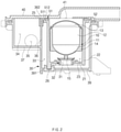
- FIG. 2 is a longitudinal view of the condensate trap apparatus 1 according to the embodiment of the present disclosure.
- FIG. 3 is an exploded view of the condensate trap apparatus 1 according to the embodiment of the present disclosure.
- the condensate trap apparatus 1 may include an inlet 41, a storage space 21, a discharge part 30, and a buoyant body 10, and may further include a cover 40.
- a plate-shaped cover 40 is covered on a case 39 of the discharge part 30 that functions as an outer wall that surrounds overall elements to constitute an integral housing, and other elements may be accommodated in an interior thereof.
- a groove may be formed at a circumference of an upper end of the case 39, and an annular case packing 52 may be inserted into the groove.
- the case packing 52 has a wing structure, and seals an interior of the case 39 when the cover 40 is covered.
- the case 39 has a three-dimensional shape as if substantially two rectangular parallelepipeds were stuck to each other, but the shape is not limited thereto.
- a vertical direction refers to a height direction of the case 39 illustrated in the drawings. That is, the case 39 may have a shape that is opened in the vertical direction, and the cover 40 may be coupled to an opened portion of the case 39 along the vertical direction to cover the opened portion.
- a horizontal direction refers to a direction that is perpendicular to the vertical direction.
- the inlet 41 is an opening, through which the condensate produced by the boiler is introduced, and may be formed at a location, at which an introduction pipeline and the cover 40 are connected to each other, and communicates an interior of the introduction pipeline and the storage space 21.
- the introduction pipeline is a pipeline configured such that the condensate obtained when exhaust gas of the boiler is condensed in an interior thereof flows therethrough.
- the condensate that flows in the introduction pipeline is delivered to the storage space 21 through the inlet 41.
- the inlet 41 is formed in the vertical direction while passing through a portion of the cover 40, but a location of the inlet 41 is not limited thereto.
- the storage space 21 is a space that accommodates the condensate introduced from the inlet 41. As the condensate is continuously introduced into the storage space 21, a level of the condensate in the storage space 21 may become gradually higher.
- the condensate trap apparatus 1 may further include the separation preventing wall 20 that defines the storage space 21.
- the separation preventing wall 20 is a partition wall that surrounds the buoyant body 10 and of which at least a portion of an inner surface is spaced apart from an outer surface of the buoyant body 10, and extends along the vertical direction and vertically upper and lower sides may be opened.
- the separation preventing wall 20 may have a uniform height in the vertical direction such that an inside and an outside of the separation preventing wall 20 are not communicated with each other along the horizontal direction that is perpendicular to the vertical direction that is a direction, in which an outlet 31 is opened.
- the separation preventing wall 20 may have a tubular side wall 22. Because the side wall 22 surrounds the buoyant body 10, the buoyant body 10 may elevate due to a buoyant force of the condensate in the vertical direction, but a location of the buoyant body 10 is restricted by the separation preventing wall 20 such that the buoyant body 10 is not separated in another direction that is not parallel to the vertical direction.
- a lower wall 23 may be disposed on a lower side of the side wall 22 of the separation preventing wall 20.
- the lower wall 23 includes a low wall opening that is opened in the vertical direction such that a discharge packing 32 surrounding the outlet 31 is inserted thereinto
- a fixing boss 26 may be formed in the separation preventing wall 20, and may be coupled to a fixing recess 391 formed at a portion of an inner surface of the case 39. As the fixing boss 26 and the fixing recess 391 are coupled to each other, a relative location of the separation preventing wall 20 and the case 39 may be fixed. In the embodiment of the present disclosure, it is illustrated that the fixing boss 26 protrudes from a lower side of the separation preventing wall 20 toward a vertically lower side and is coupled to the fixing recess 391 formed on, among inner surfaces of the case 39, a surface located on a lower side, but a location and a structure thereof are not limited thereto.
- the fixing boss may be formed in the case 39 and the fixing recess may be formed in the separation preventing wall 20 to perform the same function.
- the separation preventing wall 20 is fixed by the fixing boss 26 and the fixing recess 391 while an outer surface of the separation preventing wall 20 and an inner surface of the case 39 are spaced apart from each other.
- a first discharge space 33 that is a space formed between the outer surface of the separation preventing wall 20 and the inner surface of the case 39 will be described below in detail in a description of a trap structure of the discharge part 30.
- the storage space 21 may be a space defined by the side wall 22 and the lower wall 23 of the separation preventing wall 20, and the cover 40.
- the condensate trap apparatus 1 may further include a prevention wall packing 51.
- the annular prevention wall packing 51 may be disposed on a vertically upper side of the side wall 22 of the separation preventing wall 20.
- the prevention wall packing 51 is disposed to prevent the condensate from overflowing to another location of the interior of the condensate trap apparatus 1 as the condensate that is more than an accommodation capacity of the interior space is introduced when the cover 40 covers the separation preventing wall 20. Accordingly, when the cover 40 is covered, the flexible prevention wall packing 51 is disposed between the separation preventing wall 20 and the cover 40, whereby materials are prevented from being introduced and discharged through an aperture between the separation preventing wall 20 and the cover 40.
- the prevention wall packing 51 includes an annular part 511 inserted into an annular groove formed at an upper end of the side wall 22, and a wing part 512 protruding from the annular part 511 to a radially inner side and a vertically upper side.
- the wing part 512 is elastically deformed to block the above-described aperture while contacting a lower surface of the cover 40.
- a coupling member such as a screw for coupling the corresponding part when the condensate trap apparatus 1 is assembled may not be necessary.
- the buoyant body 10 is an element that may close the outlet 31 when it is seated on the discharge part 30 or open the outlet 31 when it is spaced apart from the discharge part 30 while floating in the condensate.
- the buoyant body 10 includes a closed part 11, a support part 12, and a head part 13, and may be formed in a shape of an acorn. Although a spherical buoyant body may be considered, the buoyant body of the shape occupies a small volume in the storage space 21 and thus a buoyant force applied by the condensate is small, so that the buoyant body may not float smoothly when a high pressure is applied.
- the closed part 11 is a portion of the buoyant body 10 seated on the discharge part 30.
- the closed part 11 has a shape that is convex toward a vertically lower side, and may close the outlet 31 when it is seated on the discharge packing 32 of the discharge part 30.
- the closed part 11 may have a shape of a portion of a sphere.
- the support part 12 extends from the closed part 11 to a vertically upper side.
- the support part 12 may have a columnar shape.
- the support part 12 may have an outer surface that is continuous from an outer surface of the closed part 11. Accordingly, because the support part 12 extends from the closed part 11 of the above-described shape, the support part 12 may have a cylindrical shape.
- the head part 13 is a portion of the buoyant body 10 that is disposed at an upper end of the support part 12 and is convex toward the vertically upper side.
- the head part 13 also may have an outer surface that is continuous from an outer surface of the support part 12, and may have a shape of a portion of a sphere.
- the head part 13 and the support part 12 are expressed to be convex along opposite directions and a radius of curvature of a profile of the head part 13 in a longitudinal section thereof is larger than a radius of curvature of a profile of the closed part, but the shape thereof is not limited thereto.
- the buoyant body 10 may further include a guide wing 14.
- the guide wing 14 is a portion of the buoyant body 10 that prevents the support part 12 from being biased from a state, in which the support part 12 is arranged along the vertical direction, when the support part 12 floats in the condensate or is seated on the discharge packing 32.
- the guide wing 14 is an element that protrudes from an outer surface of at least one of the support part 12 or the closed part 11, and an outer end of which is disposed adjacent to the separation preventing wall 20.
- a plurality of guide wings 14 may be provided to protrude from an outer surface of the support part 12 or the closed part 11 radially or to be spaced apart from each other by a specific interval along a circumference of the support part 12 or the closed part 11. In the embodiment of the present disclosure, a total of four guide wings 14 are provided, but the number of the guide wings 14 is not limited thereto.
- the guide wings 14 may extend along a vertical direction. Accordingly, as illustrated, the guide wings 14 may be disposed over both of the support part 12 and the closed part 11. While the guide wing 14 extends along the vertical direction, an outermost surface of the guide wing 14 may have a shape that is parallel to an inner surface of the separation preventing wall 20.
- the buoyant body 10 may further include a weight 151 formed of a material having a density that is higher than that of a material constituting the support part 12, at a lower end of the closed part 11.
- the weight 151 may be disposed at the above-described location as a buoyant body boss 15 protruding from a lower end of the closed part 11 to a vertically lower side is inserted into a recess. Because a density of the weight 151 is higher than a density of the material that constitutes the support part 12, a center of weight of the entire buoyant body 10 may become lower as compared with a case, in which there is no weight 151. Accordingly, the buoyant body 10 may float or be submerged more stably.
- the weight 151 may be inserted into the outlet 31 when the buoyant body 10 closes the outlet 31. Accordingly, even when the buoyant body 10 floats and the outlet 31 is opened, a situation, in which the buoyant body 10 is turned over and cannot return to a normal driving location and a normal posture again, may be prevented.
- a location of the weight 151 may be identified in FIGS. 4 to 6 as follows.
- the buoyant body 10 has the above-described shape, a higher buoyant force is applied from the condensate to the buoyant body 10 than to a spherical buoyant body, so that the condensate may be discharged as the buoyant body 10 floats more easily under a high pressure. Furthermore, because a support structure is present, the buoyant body 10 may stably move while not causing a problem of overturning even while the buoyant body 10 repeatedly floats or is submerged.
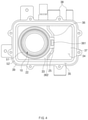
- FIG. 4 is a plan view of the condensate trap apparatus 1 according to an embodiment of the present disclosure, in a state in which the cover 40 thereof is removed.
- FIG. 5 is a longitudinal sectional view illustrating a situation, in which the buoyant body 10 of the condensate trap apparatus 1 is submerged to be seated on the discharge packing 32 according to an embodiment of the present disclosure.
- FIG. 6 is an enlarged view illustrating a portion that is adjacent to the buoyant body 10 and the discharge packing 32.
- the discharge part 30 will be described with reference to FIGS. 4 to 6 .
- the discharge part 30 is an element including structures that discharge the condensate stored in the storage space 21.
- the outlet 31 is an opening that is opened in a direction that is perpendicular to a lower wall opening formed in the lower wall 23 of the separation preventing wall 20, and discharges the condensate from the storage space 21 when being opened.
- the outlet 31 communicates the storage space 21 and the first discharge space 33, which will be described below.
- the annular discharge packing 32 is disposed to surround the outlet 31.
- the discharge packing 32 including the discharge part 30 has a part that extends to be inclined toward a radial center of the outlet 31 and a vertically upper side. Accordingly, when the buoyant body 10 is seated on the discharge packing 32, an outer surface of the buoyant body 10 contacts the discharge packing 32, whereby the outlet 31 is closed by blocking the condensate that flows to the outlet 31. Furthermore, as the buoyant body 10 floats and is spaced apart from the discharge packing 32, the outlet 31 may be opened.
- the discharge packing 32 may be formed of a material having elasticity to contact the buoyant body 10 better and thus maintain the waterproofness.
- the discharge packing 32 may include an extension part 323 that is a part extending from the outlet 31 to be inclined toward a radial center of the outlet 31 and the vertically upper side, a first contact part 321, and a second contact part 322.
- the first contact part 321 is a portion that is disposed on an outermost side with respect to a radial direction of the outlet 31 to contact the closed part 11. Because the first contact part 321 is disposed on an outermost side of the extension part 323 with respect to the radial direction, it is disposed at an upper end of the extension part 323 with respect to the vertical direction.
- the first contact part 321, in a longitudinal sectional view of FIG. 6 may have a cross-section that protrudes from the extension part 323 to a vertically upper side. Accordingly, the buoyant body 10 that is submerged and is seated on the discharge packing 32 may be seated on the first contact part 321.
- the second contact part 322 is a portion that is spaced apart from the first contact part 321 with respect to the radial direction, and, like the first contact part 321, has a shape that protrudes from the extension part 323 to the vertically upper side, in a longitudinal section thereof.
- the second contact part 322 has an annular shape, and contacts the outer surface of the buoyant body 10 when the buoyant body 10 is seated on the discharge packing 32.
- the discharge packing 32 may have a waterproof structure of a dual structure including the first contact part 321 and the second contact part 322. Because the discharge packing 32 has the dual structure, the waterproofness of the outlet 31 is maintained better in a state, in which the buoyant body 10 is seated on the discharge packing 32.
- the discharge packing 32 may include a packing flange 325, a packing column part 324, and a packing stopper 326.
- the packing column part 324 that has an annular shape to surround the outlet 31 may be inserted into the lower wall opening to complete assembly of the discharge packing 32.
- the annular packing stopper 326 disposed at a lower end of the packing column part 324 may have a cross-section that is convex toward a vertically lower side in a longitudinal section thereof such that the packing column part 324 is inserted into the lower wall opening more easily. Accordingly, when the discharge packing 32 is pressed to the vertically lower side in a state, in which the packing stopper 326 contacts the lower wall opening, the discharge packing 32 may be easily inserted.
- a diameter of the packing stopper 326 may be larger than a diameter of the packing column part 324. Accordingly, when the discharge packing 32 is pressed to the vertically lower side for assembly, like a snap-fit, the packing stopper 326 may pass through the lower wall opening of the packing stopper 326 and be disposed on the vertically lower side of the lower wall 23. At the same time, the packing column part 324 may be disposed on an inside of the lower wall opening. Because the packing stopper 326 stops the discharge packing 32, the discharge packing 32 may be prevented from being separated upwards.
- the packing flange 325 may be formed from the packing column part 324.
- the packing flange 325 is a portion that protrudes from the packing column part 324 in a radially outer side, and is disposed adjacent to the vertically upper side of the packing column part 324. Accordingly, the packing flange 325 may be seated on an inner side of the lower wall 23 when the discharge packing 32 is assembled. Because the packing flange 325 stops the discharge packing 32, the discharge packing 32 may be prevented from being separated on the vertically lower side. That is, because the lower wall 23 is disposed between the packing stopper 326 and the packing flange 325, the discharge packing 32 may be fixed to the lower wall 23.
- outlet 31 and the buoyant body 10 that closes the outlet 31 are disposed immediately after the inlet 41 is disposed, an element that solves a pressure through a bypass is not separately necessary.
- the discharge part 30 may further include a "U"-shaped trap. To form the trap, the discharge part 30 may further include the first discharge space 33 and a second discharge space 34.
- the first discharge space 33 means a space that accommodates the condensate discharged through the outlet 31. Accordingly, the first discharge space 33 and the storage space 21 may be communicated with each other through the outlet 31.
- At least a portion of the first discharge space 33 may be disposed on a lower side of the storage space 21.
- a portion of the first discharge space 33 disposed on the lower side of the storage space 21 may receive the condensate from the storage space 21 and accommodate the condensate.
- the first discharge space 33 may surround the separation preventing wall 20.
- the first discharge space 33 may be a space formed between an outer surface of the separation preventing wall 20 and an inner surface of the case 39.
- the first discharge space 33 may include a space between the inner surface of the case 39 and the lower wall 23 and a space between the inner surface of the case 39, and a discharge partition wall 36 and the side wall 22.
- the condensate may be filled in the space between the inner surface of the case 39, and the discharge partition wall 36 and the side wall 22.
- a condensate passage 362, through which the condensate flows out from the first discharge space 33, may be disposed on an upper side of the outlet 31 with respect to the vertical direction. Accordingly, because the condensate is not discharged unless the condensate is filled in the first discharge space 33 to a specific level or more due to the shape of the first discharge space 33, a "U"-shaped trap, in which the exhaust gas is prevented from being discharged by the condensate due to a head, may be further formed. Because the trap by the buoyant body 10 and the "U"-shaped trap are disposed together, the condensate trap apparatus 1 according to the embodiment of the present disclosure may have a safer trap structure.
- a porous mesh is disposed in the condensate passage 362, it may filter out foreign substances of a specific size or more, which are carried by the condensate that passes through the condensate passage 362.
- the second discharge space 34 is a space, in which the condensate delivered from the first discharge space 33 is accommodated. Accordingly, the discharge partition wall 36 that partitions the second discharge space 34 and the first discharge space 33 may be present, and the condensate passage 362 that communicates the first discharge space 33 and the second discharge space 34 to deliver the condensate from the first discharge space 33 to the second discharge space 34 may be formed in the discharge partition wall 36.
- the discharge partition wall 36 is formed in the interior of the case 39 to partition the first discharge space 33 and the second discharge space 34.
- the discharge partition wall 36 as illustrated in FIG. 4 , extends along one direction that is perpendicular to the vertical direction, in a cross-section taken on a plane that is perpendicular to the vertical direction, and may have a portion protruding in a direction that becomes farther away from the side wall 22 of the separation preventing wall 20 at a center thereof.
- a portion of an upper end of the discharge partition wall 36 may contact the cover 40 when the cover 40 is covered, and another portion of the upper end of the discharge partition wall 36 may be spaced apart from the cover in the vertical direction when the cover 40 is covered to form the condensate passage 362.
- a portion that contacts the cover 40 may be a partition wall boss 361.
- the partition wall boss 361 is an element formed to stop a prevention wall ring 25 formed on an upper side of the separation preventing wall 20.
- the partition wall boss 361 has a protruding boss shape due to a difference of a relative height from another portion of the upper end of the discharge partition wall 36, in which the condensate passage 362 is formed.
- the partition wall boss 361 may be disposed in an area of the discharge partition wall 36 protruding in a direction that becomes farther away from the side wall 22 of the above-described separation preventing wall 20, but a location thereof is not limited thereto.
- the separation preventing wall 20 may be assembled in the case 39 while being moved to the vertically lower side. Then, the partition wall boss 361 is inserted into an opening of the prevention wall ring 25, and the separation preventing wall 20 may be coupled to the discharge partition wall 36, and a relative location thereof may be fixed.
- shapes of the partition wall boss 361 and the prevention wall ring 25 are not limited thereto, and may be modified to a structure, in which they may be coupled to each other.
- the second discharge space 34 may be a space defined by the inner surface of the case 39 and the discharge partition wall 36.
- the condensate delivered to the second discharge space 34 may be discharged to the outside through a drainage 35.
- the drainage 35 is an opening that communicates the second discharge space 34 and the outside.
- the drainage 35 may be located on an upper side of the outlet 31 with respect to the vertical direction.
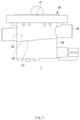
- FIG. 7 is a side view of the condensate trap apparatus 1 according to an embodiment of the present disclosure.
- the drainage 35 is disposed to be adjacent to a bottom surface of the second discharge space 34, and the condensate delivered to the second discharge space 34 is easily discharged by the drainage 35.
- the bottom surface of the second discharge space 34 may have a gradient such that a portion thereof that is adjacent to the drainage 35 is located on a lowermost side with respect to the vertical direction. Accordingly, a wall 37 located on a lower side of the inner surface of the case 39, which defines the second discharge space 34, may be inclined in the vertically upper side as it goes from the drainage 35 in a horizontal direction. According to the gradient, water may be easily discharged through the drainage 35.
- An auxiliary line 38 may be further connected to the second discharge space 34.
- the auxiliary line 38 may include a safety valve line and a drain line that are necessary when the boiler is installed. That is, to deliver other water generated by the boiler that produces the condensate to the second discharge space 34, the lines communicated with the second discharge space 34 become the auxiliary line, but the kinds of the lines included in the auxiliary line are not limited thereto.
- the auxiliary line 38 is communicated with the second discharge space 34, the water is not discharged to the outside separately by the lines, and the water may be discharged to the outside through one simplified exit, and thus it is easy to manage the discharged water.
- a location, at which the auxiliary line 38 is communicated with the second discharge space 34, may be on an upper side of the drainage 35 with respect to the vertical direction. Accordingly, the water is delivered to the second discharge space 34 through the auxiliary line 38, and the water stored in the second discharge space 34 is not discharged through the auxiliary line 38 but may be discharged through the drainage 35.
Landscapes
- Engineering & Computer Science (AREA)
- General Engineering & Computer Science (AREA)
- Mechanical Engineering (AREA)
- Physics & Mathematics (AREA)
- Thermal Sciences (AREA)
- Chemical & Material Sciences (AREA)
- Combustion & Propulsion (AREA)
- Float Valves (AREA)
- Sink And Installation For Waste Water (AREA)
Abstract
Description
- The present disclosure relates to a condensate trap apparatus used for a boiler, and a buoyant body therefor.
- To heat heating water of a boiler, a burner that is a heat source exchanges heat with the heating water by heating air. Exhaust gas produced as a result is condensed as a temperature thereof decreases, and a phase of the exhaust gas may be changed into a form of condensate.
- The condensate is generally acidic due to components of the exhaust gas, and expedites corrosion of components of the boiler when it is continuously preserved in an interior the boiler. Accordingly, it is necessary to discharge the condensate in an appropriate method.
- Meanwhile, while the condensate is discharged in the method, the exhaust gas that has not been condensed but is left in a gaseous state also may be discharged together with the condensate. However, unlike the condensate, because the exhaust gas is diffused into the air while being discharged, it causes serious environmental contamination, and may cause carbon monoxide and carbon dioxide when it is introduced into the interior, and thus may influence the safety of residential environments and life spaces.
- Accordingly, to discharge the condensate but not to discharge the exhaust gas, various trap apparatuses have been used in the field of boilers.
- The present disclosure has been made in an effort to solve the above-mentioned problems, and provides a condensate trap apparatus that discharges condensate but does not discharge exhaust gas, and a buoyant body therefor.
- According an embodiment, a condensate trap apparatus includes an inlet, through which condensate is introduced, a storage space, in which the condensate introduced from the inlet is stored, a discharge part including an outlet that discharges the stored condensate from the storage space, and a buoyant body including a closed part formed to be convex toward a vertically lower side such that the buoyant body is seated on the discharge part to close the outlet, and a columnar support part extending vertically upwards from the closed part.
- According an embodiment, a buoyant body seated on a discharge part including an outlet configured such that condensate stored in a storage space is discharged from the storage space includes a closed part formed to be convex toward a vertically lower side to be seated on the discharge part to close the outlet, and having a shape of a portion of a sphere, a columnar support part extending from the closed part to a vertically upper side, and having an outer surface that is continuous to an outer surface of the closed part, and a head part disposed at an end of the support part and formed to be convex toward a vertically upper side.
- Accordingly, the buoyant body may float better in the condensate, and may discharge the condensate smoothly.
- Because the buoyant body floats stably, whereby the buoyant body may be prevented from turning over while an operation of the buoyant body is repeated.
-
-
FIG. 1 is a perspective view of a condensate trap apparatus according to an embodiment of the present disclosure. -
FIG. 2 is a longitudinal sectional view of a condensate trap apparatus according to an embodiment of the present disclosure. -
FIG. 3 is an exploded view of a condensate trap apparatus according to an embodiment of the present disclosure. -
FIG. 4 is a plan view of a condensate trap apparatus according to an embodiment of the present disclosure, in a state in which a cover thereof is removed. -
FIG. 5 is a longitudinal sectional view illustrating a situation, in which a buoyant body of a condensate trap apparatus is submerged to be seated on a discharge packing according to an embodiment of the present disclosure. -
FIG. 6 is an enlarged view illustrating a portion that is adjacent to a buoyant body and a discharge packing. -
FIG. 7 is a side view of a condensate trap apparatus according to an embodiment of the present disclosure. - A claim for priority is made to
Korean Patent Application No. 10-2019-0052468 filed on May 3, 2019 - Hereinafter, some embodiments of the present disclosure will be described in detail with reference to the exemplary drawings. Throughout the specification, it is noted that the same or like reference numerals denote the same or like components even though they are provided in different drawings. Further, in the following description of the present disclosure, a detailed description of known functions and configurations incorporated herein will be omitted when it may make the subject matter of the present disclosure rather unclear.
- In addition, terms, such as first, second, A, B, (a), (b) or the like may be used herein when describing components of the present disclosure. The terms are provided only to distinguish the components from other components, and the essences, sequences, orders, and the like of the components are not limited by the terms. When it is described that one element is connected, coupled, or electrically connected to another element, the element may be directly connected or coupled to the other element, but a third element may be connected, coupled, or electrically connected between the elements.
- To adjust discharge of condensate, a trap apparatus in a scheme of discharging the condensate only when an outlet blocked by a buoyant body is opened after the condensate passes through a membrane may be considered. In the trap apparatus, when the condensate floats to a specific water level or more, the buoyant body is spaced apart from the outlet to open the outlet so that the condensate is discharged.
- However, a pressure in an interior of a body of the trap apparatus increases due to a structure thereof as the trap apparatus is used, and the trap apparatus may be consistently used smoothly only when the pressure is solved by a bypass line.
- Hereinafter, a structure of a
condensate trap apparatus 1 according to an embodiment of the present disclosure capable of solving the problems will be described with reference to the accompanying drawings. -
FIG. 1 is a perspective view of thecondensate trap apparatus 1 according to an embodiment of the present disclosure.FIG. 2 is a longitudinal view of thecondensate trap apparatus 1 according to the embodiment of the present disclosure.FIG. 3 is an exploded view of thecondensate trap apparatus 1 according to the embodiment of the present disclosure. - Referring to
FIGS. 1 to 3 , thecondensate trap apparatus 1 according to the embodiment of the present disclosure may include aninlet 41, astorage space 21, adischarge part 30, and abuoyant body 10, and may further include acover 40. A plate-shaped cover 40 is covered on acase 39 of thedischarge part 30 that functions as an outer wall that surrounds overall elements to constitute an integral housing, and other elements may be accommodated in an interior thereof. A groove may be formed at a circumference of an upper end of thecase 39, and anannular case packing 52 may be inserted into the groove. The case packing 52 has a wing structure, and seals an interior of thecase 39 when thecover 40 is covered. - In the embodiment of the present disclosure, it is expressed that the
case 39 has a three-dimensional shape as if substantially two rectangular parallelepipeds were stuck to each other, but the shape is not limited thereto. In the specification, a vertical direction refers to a height direction of thecase 39 illustrated in the drawings. That is, thecase 39 may have a shape that is opened in the vertical direction, and thecover 40 may be coupled to an opened portion of thecase 39 along the vertical direction to cover the opened portion. A horizontal direction refers to a direction that is perpendicular to the vertical direction. -
Inlet 41, StorageSpace 21, and Separation PreventingWall 20 - The
inlet 41 is an opening, through which the condensate produced by the boiler is introduced, and may be formed at a location, at which an introduction pipeline and thecover 40 are connected to each other, and communicates an interior of the introduction pipeline and thestorage space 21. The introduction pipeline is a pipeline configured such that the condensate obtained when exhaust gas of the boiler is condensed in an interior thereof flows therethrough. The condensate that flows in the introduction pipeline is delivered to thestorage space 21 through theinlet 41. In the embodiment of the present disclosure, it is illustrated that theinlet 41 is formed in the vertical direction while passing through a portion of thecover 40, but a location of theinlet 41 is not limited thereto. - The
storage space 21 is a space that accommodates the condensate introduced from theinlet 41. As the condensate is continuously introduced into thestorage space 21, a level of the condensate in thestorage space 21 may become gradually higher. - The
condensate trap apparatus 1 according to the embodiment of the present disclosure may further include theseparation preventing wall 20 that defines thestorage space 21. Theseparation preventing wall 20 is a partition wall that surrounds thebuoyant body 10 and of which at least a portion of an inner surface is spaced apart from an outer surface of thebuoyant body 10, and extends along the vertical direction and vertically upper and lower sides may be opened. Theseparation preventing wall 20 may have a uniform height in the vertical direction such that an inside and an outside of theseparation preventing wall 20 are not communicated with each other along the horizontal direction that is perpendicular to the vertical direction that is a direction, in which anoutlet 31 is opened. - To provide the shape, the
separation preventing wall 20 may have atubular side wall 22. Because theside wall 22 surrounds thebuoyant body 10, thebuoyant body 10 may elevate due to a buoyant force of the condensate in the vertical direction, but a location of thebuoyant body 10 is restricted by theseparation preventing wall 20 such that thebuoyant body 10 is not separated in another direction that is not parallel to the vertical direction. - A
lower wall 23 may be disposed on a lower side of theside wall 22 of theseparation preventing wall 20. Thelower wall 23 includes a low wall opening that is opened in the vertical direction such that adischarge packing 32 surrounding theoutlet 31 is inserted thereinto - A
fixing boss 26 may be formed in theseparation preventing wall 20, and may be coupled to afixing recess 391 formed at a portion of an inner surface of thecase 39. As thefixing boss 26 and thefixing recess 391 are coupled to each other, a relative location of theseparation preventing wall 20 and thecase 39 may be fixed. In the embodiment of the present disclosure, it is illustrated that the fixingboss 26 protrudes from a lower side of theseparation preventing wall 20 toward a vertically lower side and is coupled to the fixingrecess 391 formed on, among inner surfaces of thecase 39, a surface located on a lower side, but a location and a structure thereof are not limited thereto. For example, the fixing boss may be formed in thecase 39 and the fixing recess may be formed in theseparation preventing wall 20 to perform the same function. - The
separation preventing wall 20 is fixed by the fixingboss 26 and the fixingrecess 391 while an outer surface of theseparation preventing wall 20 and an inner surface of thecase 39 are spaced apart from each other. Afirst discharge space 33 that is a space formed between the outer surface of theseparation preventing wall 20 and the inner surface of thecase 39 will be described below in detail in a description of a trap structure of thedischarge part 30. - Because the
cover 40 is covered, thestorage space 21 may be a space defined by theside wall 22 and thelower wall 23 of theseparation preventing wall 20, and thecover 40. In this situation, to maintain waterproofness of a border of theside wall 22 and thecover 40, thecondensate trap apparatus 1 according to the embodiment of the present disclosure may further include a prevention wall packing 51. - The annular prevention wall packing 51 may be disposed on a vertically upper side of the
side wall 22 of theseparation preventing wall 20. The prevention wall packing 51 is disposed to prevent the condensate from overflowing to another location of the interior of thecondensate trap apparatus 1 as the condensate that is more than an accommodation capacity of the interior space is introduced when thecover 40 covers theseparation preventing wall 20. Accordingly, when thecover 40 is covered, the flexible prevention wall packing 51 is disposed between theseparation preventing wall 20 and thecover 40, whereby materials are prevented from being introduced and discharged through an aperture between theseparation preventing wall 20 and thecover 40. - For the operation, the prevention wall packing 51 includes an
annular part 511 inserted into an annular groove formed at an upper end of theside wall 22, and awing part 512 protruding from theannular part 511 to a radially inner side and a vertically upper side. When being covered by thecover 40, thewing part 512 is elastically deformed to block the above-described aperture while contacting a lower surface of thecover 40. - Because the waterproofness may be maintained even though the
separation preventing wall 20 and thecover 40 are not firmly coupled to each other at the border thereof as the prevention wall packing 51 is disposed, a coupling member such as a screw for coupling the corresponding part when thecondensate trap apparatus 1 is assembled may not be necessary. - The
buoyant body 10 is an element that may close theoutlet 31 when it is seated on thedischarge part 30 or open theoutlet 31 when it is spaced apart from thedischarge part 30 while floating in the condensate. Thebuoyant body 10 includes aclosed part 11, asupport part 12, and ahead part 13, and may be formed in a shape of an acorn. Although a spherical buoyant body may be considered, the buoyant body of the shape occupies a small volume in thestorage space 21 and thus a buoyant force applied by the condensate is small, so that the buoyant body may not float smoothly when a high pressure is applied. - The
closed part 11 is a portion of thebuoyant body 10 seated on thedischarge part 30. Theclosed part 11 has a shape that is convex toward a vertically lower side, and may close theoutlet 31 when it is seated on the discharge packing 32 of thedischarge part 30. Theclosed part 11 may have a shape of a portion of a sphere. - The
support part 12 extends from theclosed part 11 to a vertically upper side. Thesupport part 12 may have a columnar shape. Thesupport part 12 may have an outer surface that is continuous from an outer surface of theclosed part 11. Accordingly, because thesupport part 12 extends from theclosed part 11 of the above-described shape, thesupport part 12 may have a cylindrical shape. - The
head part 13 is a portion of thebuoyant body 10 that is disposed at an upper end of thesupport part 12 and is convex toward the vertically upper side. Thehead part 13 also may have an outer surface that is continuous from an outer surface of thesupport part 12, and may have a shape of a portion of a sphere. In the embodiment of the present disclosure, thehead part 13 and thesupport part 12 are expressed to be convex along opposite directions and a radius of curvature of a profile of thehead part 13 in a longitudinal section thereof is larger than a radius of curvature of a profile of the closed part, but the shape thereof is not limited thereto. - The
buoyant body 10 may further include aguide wing 14. Theguide wing 14 is a portion of thebuoyant body 10 that prevents thesupport part 12 from being biased from a state, in which thesupport part 12 is arranged along the vertical direction, when thesupport part 12 floats in the condensate or is seated on the discharge packing 32. - The
guide wing 14 is an element that protrudes from an outer surface of at least one of thesupport part 12 or theclosed part 11, and an outer end of which is disposed adjacent to theseparation preventing wall 20. A plurality ofguide wings 14 may be provided to protrude from an outer surface of thesupport part 12 or theclosed part 11 radially or to be spaced apart from each other by a specific interval along a circumference of thesupport part 12 or theclosed part 11. In the embodiment of the present disclosure, a total of fourguide wings 14 are provided, but the number of theguide wings 14 is not limited thereto. - The
guide wings 14 may extend along a vertical direction. Accordingly, as illustrated, theguide wings 14 may be disposed over both of thesupport part 12 and theclosed part 11. While theguide wing 14 extends along the vertical direction, an outermost surface of theguide wing 14 may have a shape that is parallel to an inner surface of theseparation preventing wall 20. - The
buoyant body 10 may further include aweight 151 formed of a material having a density that is higher than that of a material constituting thesupport part 12, at a lower end of theclosed part 11. Theweight 151 may be disposed at the above-described location as abuoyant body boss 15 protruding from a lower end of theclosed part 11 to a vertically lower side is inserted into a recess. Because a density of theweight 151 is higher than a density of the material that constitutes thesupport part 12, a center of weight of the entirebuoyant body 10 may become lower as compared with a case, in which there is noweight 151. Accordingly, thebuoyant body 10 may float or be submerged more stably. - The
weight 151 may be inserted into theoutlet 31 when thebuoyant body 10 closes theoutlet 31. Accordingly, even when thebuoyant body 10 floats and theoutlet 31 is opened, a situation, in which thebuoyant body 10 is turned over and cannot return to a normal driving location and a normal posture again, may be prevented. A location of theweight 151 may be identified inFIGS. 4 to 6 as follows. - Because the
buoyant body 10 has the above-described shape, a higher buoyant force is applied from the condensate to thebuoyant body 10 than to a spherical buoyant body, so that the condensate may be discharged as thebuoyant body 10 floats more easily under a high pressure. Furthermore, because a support structure is present, thebuoyant body 10 may stably move while not causing a problem of overturning even while thebuoyant body 10 repeatedly floats or is submerged. -
FIG. 4 is a plan view of thecondensate trap apparatus 1 according to an embodiment of the present disclosure, in a state in which thecover 40 thereof is removed.FIG. 5 is a longitudinal sectional view illustrating a situation, in which thebuoyant body 10 of thecondensate trap apparatus 1 is submerged to be seated on the discharge packing 32 according to an embodiment of the present disclosure.FIG. 6 is an enlarged view illustrating a portion that is adjacent to thebuoyant body 10 and the discharge packing 32. - The
discharge part 30 will be described with reference toFIGS. 4 to 6 . Thedischarge part 30 is an element including structures that discharge the condensate stored in thestorage space 21. Thedischarge part 30, accordingly, includes theoutlet 31 that discharges the condensate from thestorage space 21. - The
outlet 31 is an opening that is opened in a direction that is perpendicular to a lower wall opening formed in thelower wall 23 of theseparation preventing wall 20, and discharges the condensate from thestorage space 21 when being opened. In the embodiment of the present disclosure, theoutlet 31 communicates thestorage space 21 and thefirst discharge space 33, which will be described below. - The annular discharge packing 32 is disposed to surround the
outlet 31. The discharge packing 32 including thedischarge part 30 has a part that extends to be inclined toward a radial center of theoutlet 31 and a vertically upper side. Accordingly, when thebuoyant body 10 is seated on the discharge packing 32, an outer surface of thebuoyant body 10 contacts the discharge packing 32, whereby theoutlet 31 is closed by blocking the condensate that flows to theoutlet 31. Furthermore, as thebuoyant body 10 floats and is spaced apart from the discharge packing 32, theoutlet 31 may be opened. - The discharge packing 32 may be formed of a material having elasticity to contact the
buoyant body 10 better and thus maintain the waterproofness. The discharge packing 32 may include anextension part 323 that is a part extending from theoutlet 31 to be inclined toward a radial center of theoutlet 31 and the vertically upper side, afirst contact part 321, and asecond contact part 322. - The
first contact part 321 is a portion that is disposed on an outermost side with respect to a radial direction of theoutlet 31 to contact theclosed part 11. Because thefirst contact part 321 is disposed on an outermost side of theextension part 323 with respect to the radial direction, it is disposed at an upper end of theextension part 323 with respect to the vertical direction. Thefirst contact part 321, in a longitudinal sectional view ofFIG. 6 , may have a cross-section that protrudes from theextension part 323 to a vertically upper side. Accordingly, thebuoyant body 10 that is submerged and is seated on the discharge packing 32 may be seated on thefirst contact part 321. - The
second contact part 322 is a portion that is spaced apart from thefirst contact part 321 with respect to the radial direction, and, like thefirst contact part 321, has a shape that protrudes from theextension part 323 to the vertically upper side, in a longitudinal section thereof. Thesecond contact part 322 has an annular shape, and contacts the outer surface of thebuoyant body 10 when thebuoyant body 10 is seated on the discharge packing 32. - The discharge packing 32 may have a waterproof structure of a dual structure including the
first contact part 321 and thesecond contact part 322. Because the discharge packing 32 has the dual structure, the waterproofness of theoutlet 31 is maintained better in a state, in which thebuoyant body 10 is seated on the discharge packing 32. - The discharge packing 32 may include a
packing flange 325, apacking column part 324, and a packingstopper 326. Thepacking column part 324 that has an annular shape to surround theoutlet 31 may be inserted into the lower wall opening to complete assembly of the discharge packing 32. Then, theannular packing stopper 326 disposed at a lower end of thepacking column part 324 may have a cross-section that is convex toward a vertically lower side in a longitudinal section thereof such that thepacking column part 324 is inserted into the lower wall opening more easily. Accordingly, when the discharge packing 32 is pressed to the vertically lower side in a state, in which thepacking stopper 326 contacts the lower wall opening, the discharge packing 32 may be easily inserted. - A diameter of the packing
stopper 326 may be larger than a diameter of thepacking column part 324. Accordingly, when the discharge packing 32 is pressed to the vertically lower side for assembly, like a snap-fit, the packingstopper 326 may pass through the lower wall opening of the packingstopper 326 and be disposed on the vertically lower side of thelower wall 23. At the same time, thepacking column part 324 may be disposed on an inside of the lower wall opening. Because the packingstopper 326 stops the discharge packing 32, the discharge packing 32 may be prevented from being separated upwards. - The packing
flange 325 may be formed from thepacking column part 324. The packingflange 325 is a portion that protrudes from thepacking column part 324 in a radially outer side, and is disposed adjacent to the vertically upper side of thepacking column part 324. Accordingly, the packingflange 325 may be seated on an inner side of thelower wall 23 when the discharge packing 32 is assembled. Because the packingflange 325 stops the discharge packing 32, the discharge packing 32 may be prevented from being separated on the vertically lower side. That is, because thelower wall 23 is disposed between the packingstopper 326 and the packingflange 325, the discharge packing 32 may be fixed to thelower wall 23. - Because the
outlet 31 and thebuoyant body 10 that closes theoutlet 31 are disposed immediately after theinlet 41 is disposed, an element that solves a pressure through a bypass is not separately necessary. - The
discharge part 30 may further include a "U"-shaped trap. To form the trap, thedischarge part 30 may further include thefirst discharge space 33 and asecond discharge space 34. - The
first discharge space 33 means a space that accommodates the condensate discharged through theoutlet 31. Accordingly, thefirst discharge space 33 and thestorage space 21 may be communicated with each other through theoutlet 31. - To allow the
first discharge space 33 to accommodate the condensate discharged from thestorage space 21, at least a portion of thefirst discharge space 33 may be disposed on a lower side of thestorage space 21. A portion of thefirst discharge space 33 disposed on the lower side of thestorage space 21 may receive the condensate from thestorage space 21 and accommodate the condensate. - The
first discharge space 33 may surround theseparation preventing wall 20. Thefirst discharge space 33 may be a space formed between an outer surface of theseparation preventing wall 20 and an inner surface of thecase 39. Thefirst discharge space 33 may include a space between the inner surface of thecase 39 and thelower wall 23 and a space between the inner surface of thecase 39, and adischarge partition wall 36 and theside wall 22. As the level of the condensate accommodated in a space between the inner wall of thecase 39 and thelower wall 23 becomes higher after the condensate is delivered to the corresponding space, the condensate may be filled in the space between the inner surface of thecase 39, and thedischarge partition wall 36 and theside wall 22. - A
condensate passage 362, through which the condensate flows out from thefirst discharge space 33, may be disposed on an upper side of theoutlet 31 with respect to the vertical direction. Accordingly, because the condensate is not discharged unless the condensate is filled in thefirst discharge space 33 to a specific level or more due to the shape of thefirst discharge space 33, a "U"-shaped trap, in which the exhaust gas is prevented from being discharged by the condensate due to a head, may be further formed. Because the trap by thebuoyant body 10 and the "U"-shaped trap are disposed together, thecondensate trap apparatus 1 according to the embodiment of the present disclosure may have a safer trap structure. - Because a porous mesh is disposed in the
condensate passage 362, it may filter out foreign substances of a specific size or more, which are carried by the condensate that passes through thecondensate passage 362. - The
second discharge space 34 is a space, in which the condensate delivered from thefirst discharge space 33 is accommodated. Accordingly, thedischarge partition wall 36 that partitions thesecond discharge space 34 and thefirst discharge space 33 may be present, and thecondensate passage 362 that communicates thefirst discharge space 33 and thesecond discharge space 34 to deliver the condensate from thefirst discharge space 33 to thesecond discharge space 34 may be formed in thedischarge partition wall 36. - The
discharge partition wall 36 is formed in the interior of thecase 39 to partition thefirst discharge space 33 and thesecond discharge space 34. Thedischarge partition wall 36, as illustrated inFIG. 4 , extends along one direction that is perpendicular to the vertical direction, in a cross-section taken on a plane that is perpendicular to the vertical direction, and may have a portion protruding in a direction that becomes farther away from theside wall 22 of theseparation preventing wall 20 at a center thereof. - A portion of an upper end of the
discharge partition wall 36 may contact thecover 40 when thecover 40 is covered, and another portion of the upper end of thedischarge partition wall 36 may be spaced apart from the cover in the vertical direction when thecover 40 is covered to form thecondensate passage 362. Among them, a portion that contacts thecover 40 may be apartition wall boss 361. - The
partition wall boss 361 is an element formed to stop aprevention wall ring 25 formed on an upper side of theseparation preventing wall 20. Thepartition wall boss 361 has a protruding boss shape due to a difference of a relative height from another portion of the upper end of thedischarge partition wall 36, in which thecondensate passage 362 is formed. Thepartition wall boss 361 may be disposed in an area of thedischarge partition wall 36 protruding in a direction that becomes farther away from theside wall 22 of the above-describedseparation preventing wall 20, but a location thereof is not limited thereto. - As illustrated in
FIG. 3 , theseparation preventing wall 20 may be assembled in thecase 39 while being moved to the vertically lower side. Then, thepartition wall boss 361 is inserted into an opening of theprevention wall ring 25, and theseparation preventing wall 20 may be coupled to thedischarge partition wall 36, and a relative location thereof may be fixed. However, shapes of thepartition wall boss 361 and theprevention wall ring 25 are not limited thereto, and may be modified to a structure, in which they may be coupled to each other. - The
second discharge space 34 may be a space defined by the inner surface of thecase 39 and thedischarge partition wall 36. The condensate delivered to thesecond discharge space 34 may be discharged to the outside through adrainage 35. Thedrainage 35 is an opening that communicates thesecond discharge space 34 and the outside. Thedrainage 35 may be located on an upper side of theoutlet 31 with respect to the vertical direction. -
FIG. 7 is a side view of thecondensate trap apparatus 1 according to an embodiment of the present disclosure. Referring toFIG. 7 , thedrainage 35 is disposed to be adjacent to a bottom surface of thesecond discharge space 34, and the condensate delivered to thesecond discharge space 34 is easily discharged by thedrainage 35. - The bottom surface of the
second discharge space 34 may have a gradient such that a portion thereof that is adjacent to thedrainage 35 is located on a lowermost side with respect to the vertical direction. Accordingly, awall 37 located on a lower side of the inner surface of thecase 39, which defines thesecond discharge space 34, may be inclined in the vertically upper side as it goes from thedrainage 35 in a horizontal direction. According to the gradient, water may be easily discharged through thedrainage 35. - An
auxiliary line 38 may be further connected to thesecond discharge space 34. Theauxiliary line 38 may include a safety valve line and a drain line that are necessary when the boiler is installed. That is, to deliver other water generated by the boiler that produces the condensate to thesecond discharge space 34, the lines communicated with thesecond discharge space 34 become the auxiliary line, but the kinds of the lines included in the auxiliary line are not limited thereto. - Because the
auxiliary line 38 is communicated with thesecond discharge space 34, the water is not discharged to the outside separately by the lines, and the water may be discharged to the outside through one simplified exit, and thus it is easy to manage the discharged water. - A location, at which the
auxiliary line 38 is communicated with thesecond discharge space 34, may be on an upper side of thedrainage 35 with respect to the vertical direction. Accordingly, the water is delivered to thesecond discharge space 34 through theauxiliary line 38, and the water stored in thesecond discharge space 34 is not discharged through theauxiliary line 38 but may be discharged through thedrainage 35. - Although it may have been described until now that all the elements constituting the embodiments of the present disclosure are coupled to one or coupled to be operated, the present disclosure is not essentially limited to the embodiments. That is, without departing from the purpose of the present disclosure, all the elements may be selectively coupled into one or more elements to be operated. Furthermore, because the terms, such as "comprising", "including", or "having" may mean that the corresponding element may be included unless there is a specially contradictory description, it should be construed that another element is not extruded but may be further included. In addition, unless defined otherwise, all terms used herein, including technical or scientific terms, have the same meanings as those generally understood by those skilled in the art to which the present disclosure pertains. The terms, such as the terms defined in dictionaries, which are generally used, should be construed to coincide with the context meanings of the related technologies, and are not construed as ideal or excessively formal meanings unless explicitly defined in the present disclosure.
- The above description is a simple exemplification of the technical spirits of the present disclosure, and the present disclosure may be variously corrected and modified by those skilled in the art to which the present disclosure pertains without departing from the essential features of the present disclosure. Accordingly, the embodiments disclosed in the present disclosure is not provided to limit the technical spirits of the present disclosure but provided to describe the present disclosure, and the scope of the technical spirits of the present disclosure is not limited by the embodiments. Accordingly, the technical scope of the present disclosure should be construed by the attached claims, and all the technical spirits within the equivalent ranges fall within the scope of the present disclosure.
Claims (16)
- A condensate trap apparatus comprising:an inlet, through which condensate is introduced;a storage space, in which the condensate introduced from the inlet is stored;a discharge part including an outlet configured to discharge the stored condensate from the storage space; anda buoyant body including a closed part formed to be convex toward a vertically lower side such that the buoyant body is seated on the discharge part to close the outlet, and a columnar support part extending vertically upwards from the closed part.
- The condensate trap apparatus of claim 1, wherein the closed part has a shape of a portion of a sphere, and
wherein the support part has an outer surface that is continuous from an outer surface of the closed part to have a cylindrical shape. - The condensate trap apparatus of claim 1, further comprising:
a separation preventing wall surrounding the buoyant body, disposed to be spaced apart from an outer surface of the buoyant body to define the storage space, and extending vertically upwards and downwards to prevent separation of the buoyant body. - The condensate trap apparatus of claim 3, wherein the separation preventing wall has a uniform height while surrounding the buoyant body such that an inside and an outside of the separation preventing wall are not communicated with each other along a direction that is perpendicular to a direction, in which the outlet is opened.
- The condensate trap apparatus of claim 3, wherein the buoyant body further includes:
a guide wing protruding from an outer surface of the support part or the closed part toward an outside such that the support part is not inclined from a state, in which the support part is arranged along a vertical direction, and an outer end of the guide wing is disposed adjacent to the separation preventing wall. - The condensate trap apparatus of claim 5, wherein the guide wing extends along the vertical direction.
- The condensate trap apparatus of claim 1, wherein the discharge part further includes:
an annular discharge packing surrounding the outlet, extending from an edge of the outlet to be inclined toward a radial center of the outlet and a vertically upper side such that an outer surface of the buoyant body contacts the discharge packing when the buoyant body is seated on the discharge part to close the outlet. - The condensate trap apparatus of claim 7, wherein the discharge packing has a dual structure including:an annular first contact part disposed on an outermost side with respect to a radial direction of the outlet and contacting the closed part; andan annular second contact part located to be spaced apart from the first contact part inwards, and contacting the closed part.
- The condensate trap apparatus of claim 1, wherein the buoyant body further includes:
a weight formed of a material having a density that is higher than that of a material constituting the support part, at a lower end of the closed part. - The condensate trap apparatus of claim 9, wherein the weight is inserted into the outlet when the buoyant body closes the outlet.
- The condensate trap apparatus of claim 1, wherein the buoyant body further includes:
a head part disposed at an end of the support part and formed to be convex toward a vertically upper side. - The condensate trap apparatus of claim 1, wherein the discharge part further includes:a first discharge space, in which the condensate discharged through the outlet is accommodated;a second discharge space, in which the condensate delivered from the first discharge space is accommodated;a drainage communicating the second discharge space and an outside such that the condensate accommodated in the second discharge space is discharged to the outside; anda discharge partition wall provided with a condensate passage, through which the condensate flows from the first discharge space to the second discharge space, and configured to partition the first discharge space and the second discharge space, andwherein the condensate passage is located on an upper side of the outlet with respect to a vertical direction.
- The condensate trap apparatus of claim 12, wherein the drainage is located on an upper side of the outlet with respect to the vertical direction.
- The condensate trap apparatus of claim 12, wherein the drainage is disposed to be adjacent to a bottom surface of the second discharge space, and
wherein the bottom surface of the second discharge space has a gradient such that a portion thereof that is adjacent to the drainage is located on a lowermost side with respect to the vertical direction. - The condensate trap apparatus of claim 12, further comprising:an auxiliary line communicated with the second discharge space to deliver other water generated by a boiler that produces the condensate to the second discharge space, andwherein a location, at which the auxiliary line is communicated with the second discharge space, is located on an upper side of the drainage with respect to the vertical direction.
- A buoyant body seated on a discharge part including an outlet configured such that condensate stored in a storage space is discharged from the storage space, the buoyant body comprising:a closed part formed to be convex toward a vertically lower side to be seated on the discharge part to close the outlet, and having a shape of a portion of a sphere;a columnar support part extending from the closed part to a vertically upper side, and having an outer surface that is continuous to an outer surface of the closed part; anda head part disposed at an upper end of the support part and formed to be convex toward a vertically upper side.
Applications Claiming Priority (2)
| Application Number | Priority Date | Filing Date | Title |
|---|---|---|---|
| KR1020190052468A KR102398052B1 (en) | 2019-05-03 | 2019-05-03 | Condensate trap apparatus |
| PCT/KR2020/003853 WO2020226279A1 (en) | 2019-05-03 | 2020-03-20 | Condensate trap apparatus and buoyant body therefor |
Publications (3)
| Publication Number | Publication Date |
|---|---|
| EP3964766A1 true EP3964766A1 (en) | 2022-03-09 |
| EP3964766A4 EP3964766A4 (en) | 2022-09-21 |
| EP3964766B1 EP3964766B1 (en) | 2025-05-07 |
Family
ID=73051113
Family Applications (1)
| Application Number | Title | Priority Date | Filing Date |
|---|---|---|---|
| EP20801550.3A Active EP3964766B1 (en) | 2019-05-03 | 2020-03-20 | Condensate trap apparatus |
Country Status (5)
| Country | Link |
|---|---|
| US (1) | US12169045B2 (en) |
| EP (1) | EP3964766B1 (en) |
| KR (1) | KR102398052B1 (en) |
| CN (1) | CN113785163A (en) |
| WO (1) | WO2020226279A1 (en) |
Families Citing this family (3)
| Publication number | Priority date | Publication date | Assignee | Title |
|---|---|---|---|---|
| PL72940Y1 (en) * | 2021-05-04 | 2023-03-13 | Apen Group S P A | Condensate drainage device for condensing boiler, with hydrostatic EVA gasket |
| KR102438299B1 (en) * | 2022-03-22 | 2022-08-31 | 주식회사 투씨디 | Auto drain device for liquid |
| CN116951165A (en) * | 2023-07-17 | 2023-10-27 | 南京格瑞森节能科技有限公司 | Drainage device |
Family Cites Families (55)
| Publication number | Priority date | Publication date | Assignee | Title |
|---|---|---|---|---|
| US2170247A (en) * | 1939-08-22 | Water trap for gasoline pipe lines | ||
| US245318A (en) * | 1881-08-09 | John robertson | ||
| US565457A (en) * | 1896-08-11 | Steam-trap | ||
| US635703A (en) * | 1898-11-01 | 1899-10-24 | Eureka Iron Company | Steam-trap. |
| US787504A (en) * | 1903-06-29 | 1905-04-18 | Frank Engelhard | Float. |
| US755251A (en) * | 1903-12-24 | 1904-03-22 | Sebastian Steinmitz | Steam-trap. |
| US764933A (en) * | 1904-05-12 | 1904-07-12 | Frank Engelhard | Float. |
| US918272A (en) * | 1907-08-01 | 1909-04-13 | John S Brennan | Float-valve. |
| US1039621A (en) * | 1911-09-16 | 1912-09-24 | John D Westcott | Steam-trap. |
| US1102768A (en) * | 1913-07-30 | 1914-07-07 | Fred W Leuthesser | Steam, air, and water trap valve. |
| US1334079A (en) * | 1918-05-06 | 1920-03-16 | Callicott John | Steam-trap |
| US1448972A (en) * | 1920-07-06 | 1923-03-20 | John C F Long | Steam trap |
| US1732222A (en) * | 1924-04-02 | 1929-10-22 | Empire Oil And Refining Compan | Method of and apparatus for separating ground water from petroleum |
| US1750489A (en) * | 1927-03-02 | 1930-03-11 | John W Pippin | Device for separating water from oil |
| US1995742A (en) * | 1928-01-21 | 1935-03-26 | Jr Wilhelm Linnmann | Liquid separator |
| US2029163A (en) * | 1932-04-15 | 1936-01-28 | Giovenale Benedetto | Automatic air vent for pipe lines under pressure |
| US2043074A (en) * | 1932-07-28 | 1936-06-02 | Hoffman Specialty Company | Steam trap |
| US2409220A (en) * | 1943-05-13 | 1946-10-15 | Parker Appliance Co | Sump selector valve |
| US2413430A (en) * | 1944-01-17 | 1946-12-31 | Royal A Mcintyre | Automatic drainage device |
| GB608200A (en) * | 1944-05-26 | 1948-09-10 | Const Mecaniques De Stains Soc | Improvements in float-actuated separators |
| US2935990A (en) * | 1958-05-08 | 1960-05-10 | Leslie G Biddle | Air and vapor eliminator for pipe lines |
| US3454005A (en) * | 1966-09-23 | 1969-07-08 | David H Eubanks | Automatic bailing self-sealing water trap and emergency air inlet |
| FR2062091A5 (en) * | 1969-10-10 | 1971-06-25 | Muller Jacques | |
| US3715863A (en) * | 1971-03-26 | 1973-02-13 | Bennett Pump Inc | Compact pump/air separator apparatus |
| US4132238A (en) * | 1977-04-29 | 1979-01-02 | Clark Earl A | Automatic separator valve |
| US4136009A (en) * | 1977-11-17 | 1979-01-23 | David Samiran | Adjustable float and filter assembly |
| US4529122A (en) * | 1984-05-09 | 1985-07-16 | Seymour-Sheridan, Inc. | Thermostatic steam trap assembly |
| US4742842A (en) * | 1986-02-03 | 1988-05-10 | Hamlet & Garneau Inc. | Hydro-pneumatic pressure vessels |
| CN87208192U (en) | 1987-05-17 | 1988-06-01 | 陈昭 | Floating steam trap |
| JP2557671B2 (en) * | 1987-12-11 | 1996-11-27 | 豊田合成株式会社 | Fuel cutoff valve |
| US5115798A (en) * | 1991-08-08 | 1992-05-26 | Mor-Flo Industries, Inc. | Condensate trap |
| US6425408B1 (en) * | 1995-08-02 | 2002-07-30 | Marcus J. Engle | Vacuum transfer system utilizing biased ball |
| US6167587B1 (en) * | 1997-07-09 | 2001-01-02 | Bissell Homecare, Inc. | Upright extraction cleaning machine |
| BE1010051A3 (en) * | 1996-02-29 | 1997-12-02 | Atlas Copco Airpower Nv | DEVICE FOR REMOVING LIQUIDS AND / OR IMPURITIES FROM A GAS. |
| US6145533A (en) * | 1997-03-31 | 2000-11-14 | Nelson Irrigation Corporation | Air release valve |
| JP2001200565A (en) | 1999-11-12 | 2001-07-27 | Yasumi Ota | Drain trap |
| KR200176948Y1 (en) | 1999-11-17 | 2000-04-15 | 주식회사경동보일러 | A shutoff apparatus for exhaust gas of a condensate pipe |
| US20030098061A1 (en) * | 2001-11-28 | 2003-05-29 | Charles Stuchlik | System and device for condensation management in an airconditioning system |
| IL150520A0 (en) * | 2002-07-02 | 2003-02-12 | A R I Kfar Charuv Water Supply | Gas purge valve |
| US7112308B2 (en) * | 2003-07-15 | 2006-09-26 | Smith Strom W | Sulfur trap sealing device |
| US7571739B2 (en) * | 2005-12-16 | 2009-08-11 | Steam Tech, Inc. | Condensate removal device |
| CN1730851A (en) | 2005-08-03 | 2006-02-08 | 郝建兵 | Sewer decomposer |
| JP2007225146A (en) | 2006-02-21 | 2007-09-06 | Shimoda-Ecotech Co Ltd | Drainage trap and drainage device |
| KR101191382B1 (en) | 2010-06-16 | 2012-10-15 | 롯데알미늄 주식회사 | A water-trap of a boiler |
| FR2967955B1 (en) * | 2010-11-29 | 2012-12-14 | Peugeot Citroen Automobiles Sa | CIRCUIT FOR DISPENSING WINDSCREEN LIQUID FOR MOTOR VEHICLE. |
| US20130118608A1 (en) | 2011-09-22 | 2013-05-16 | Laars Heating Systems Company | System and method for trapping and neutralizing condensate in a condensing gas appliance |
| US9216372B1 (en) * | 2012-02-06 | 2015-12-22 | Strom W. Smith | Sulfur trap |
| WO2013142804A1 (en) * | 2012-03-22 | 2013-09-26 | Controls Southeast, Inc. | Sulfur seal device |
| JP6079610B2 (en) * | 2013-02-25 | 2017-02-15 | 株式会社デンソー | Drainage device and air conditioner provided with the same |
| CN204006701U (en) | 2014-07-03 | 2014-12-10 | 盛水祥 | Condensate collector |
| WO2016056481A1 (en) | 2014-10-08 | 2016-04-14 | 株式会社テイエルブイ | Drainage recovery device |
| KR101790317B1 (en) * | 2015-10-23 | 2017-10-25 | 동아대학교 산학협력단 | Free Float Steam Trap |
| JP6729156B2 (en) * | 2016-08-09 | 2020-07-22 | 京三電機株式会社 | Fuel cutoff valve |
| KR101876200B1 (en) * | 2016-11-23 | 2018-07-10 | 린나이코리아 주식회사 | Gas boiler exhaust block equipment |
| KR102589796B1 (en) | 2017-11-08 | 2023-10-16 | 코웨이 주식회사 | Smart bed system |
-
2019
- 2019-05-03 KR KR1020190052468A patent/KR102398052B1/en active Active
-
2020
- 2020-03-20 EP EP20801550.3A patent/EP3964766B1/en active Active
- 2020-03-20 US US17/605,797 patent/US12169045B2/en active Active
- 2020-03-20 CN CN202080033366.2A patent/CN113785163A/en active Pending
- 2020-03-20 WO PCT/KR2020/003853 patent/WO2020226279A1/en not_active Ceased
Also Published As
| Publication number | Publication date |
|---|---|
| EP3964766A4 (en) | 2022-09-21 |
| EP3964766B1 (en) | 2025-05-07 |
| US12169045B2 (en) | 2024-12-17 |
| US20220316654A1 (en) | 2022-10-06 |
| KR20200127745A (en) | 2020-11-11 |
| WO2020226279A1 (en) | 2020-11-12 |
| KR102398052B1 (en) | 2022-05-16 |
| CN113785163A (en) | 2021-12-10 |
Similar Documents
| Publication | Publication Date | Title |
|---|---|---|
| US12169045B2 (en) | Condensate trap apparatus and buoyant body therefor | |
| US5918622A (en) | Separation valve | |
| US4982757A (en) | Fuel cutoff valve | |
| FI71825B (en) | ANORDNING FOER AVLUFTNING OCH / ELLER AVGASNING AV LEDNINGSSYSTEM | |
| US7008546B2 (en) | Oil, water and gas separator for swaying service | |
| KR101923999B1 (en) | Fuel valve | |
| CN1072172C (en) | Automatic drainage device for goods container | |
| KR102720355B1 (en) | Mixed liquid separator | |
| EP2622143B1 (en) | Device for causing turbulent flow in a tank assembly | |
| KR101574660B1 (en) | Gas-liquid separator using hydrophobic membrane | |
| KR100954431B1 (en) | Gas-liquid Separator for Fuel Cell System | |
| US10661044B2 (en) | Humidification chamber having suspension type float | |
| EP3705806B1 (en) | Trap apparatus of condensate water | |
| KR101584584B1 (en) | One body type gas-liquid separator | |
| EP3822194B1 (en) | Chemical container | |
| KR200425999Y1 (en) | Multifunctional Air Vent | |
| JP6867476B2 (en) | A device for extracting fuel from a tank cartridge for a fuel cell | |
| US8419842B2 (en) | Hydronic system air eliminator | |
| JPH04201718A (en) | Fuel cut-off of fuel tank | |
| KR102665478B1 (en) | Safety tank for contaminated liquid | |
| KR102581647B1 (en) | Drain system of lng cargo tank | |
| JPH0569470U (en) | Water seal device | |
| KR101621721B1 (en) | Valve for ballast tank of ship | |
| US5850848A (en) | Float valve | |
| JPH07218180A (en) | Horizontal heat exchanger |
Legal Events
| Date | Code | Title | Description |
|---|---|---|---|
| STAA | Information on the status of an ep patent application or granted ep patent |
Free format text: STATUS: THE INTERNATIONAL PUBLICATION HAS BEEN MADE |
|
| PUAI | Public reference made under article 153(3) epc to a published international application that has entered the european phase |
Free format text: ORIGINAL CODE: 0009012 |
|
| STAA | Information on the status of an ep patent application or granted ep patent |
Free format text: STATUS: REQUEST FOR EXAMINATION WAS MADE |
|
| 17P | Request for examination filed |
Effective date: 20211130 |
|
| AK | Designated contracting states |
Kind code of ref document: A1 Designated state(s): AL AT BE BG CH CY CZ DE DK EE ES FI FR GB GR HR HU IE IS IT LI LT LU LV MC MK MT NL NO PL PT RO RS SE SI SK SM TR |
|
| DAV | Request for validation of the european patent (deleted) | ||
| DAX | Request for extension of the european patent (deleted) | ||
| A4 | Supplementary search report drawn up and despatched |
Effective date: 20220819 |
|
| RIC1 | Information provided on ipc code assigned before grant |
Ipc: F16T 1/38 20060101ALI20220812BHEP Ipc: F16T 1/22 20060101ALI20220812BHEP Ipc: F24H 8/00 20220101AFI20220812BHEP |
|
| GRAP | Despatch of communication of intention to grant a patent |
Free format text: ORIGINAL CODE: EPIDOSNIGR1 |
|
| STAA | Information on the status of an ep patent application or granted ep patent |
Free format text: STATUS: GRANT OF PATENT IS INTENDED |
|
| INTG | Intention to grant announced |
Effective date: 20250110 |
|
| GRAS | Grant fee paid |
Free format text: ORIGINAL CODE: EPIDOSNIGR3 |
|
| GRAA | (expected) grant |
Free format text: ORIGINAL CODE: 0009210 |
|
| STAA | Information on the status of an ep patent application or granted ep patent |
Free format text: STATUS: THE PATENT HAS BEEN GRANTED |
|
| AK | Designated contracting states |
Kind code of ref document: B1 Designated state(s): AL AT BE BG CH CY CZ DE DK EE ES FI FR GB GR HR HU IE IS IT LI LT LU LV MC MK MT NL NO PL PT RO RS SE SI SK SM TR |
|
| REG | Reference to a national code |
Ref country code: GB Ref legal event code: FG4D |
|
| REG | Reference to a national code |
Ref country code: CH Ref legal event code: EP |
|
| REG | Reference to a national code |
Ref country code: DE Ref legal event code: R096 Ref document number: 602020050963 Country of ref document: DE |
|
| REG | Reference to a national code |
Ref country code: IE Ref legal event code: FG4D |
|
| REG | Reference to a national code |
Ref country code: NL Ref legal event code: MP Effective date: 20250507 |
|
| PG25 | Lapsed in a contracting state [announced via postgrant information from national office to epo] |
Ref country code: PT Free format text: LAPSE BECAUSE OF FAILURE TO SUBMIT A TRANSLATION OF THE DESCRIPTION OR TO PAY THE FEE WITHIN THE PRESCRIBED TIME-LIMIT Effective date: 20250908 Ref country code: FI Free format text: LAPSE BECAUSE OF FAILURE TO SUBMIT A TRANSLATION OF THE DESCRIPTION OR TO PAY THE FEE WITHIN THE PRESCRIBED TIME-LIMIT Effective date: 20250507 Ref country code: ES Free format text: LAPSE BECAUSE OF FAILURE TO SUBMIT A TRANSLATION OF THE DESCRIPTION OR TO PAY THE FEE WITHIN THE PRESCRIBED TIME-LIMIT Effective date: 20250507 |
|
| REG | Reference to a national code |
Ref country code: LT Ref legal event code: MG9D |
|
| PG25 | Lapsed in a contracting state [announced via postgrant information from national office to epo] |
Ref country code: NO Free format text: LAPSE BECAUSE OF FAILURE TO SUBMIT A TRANSLATION OF THE DESCRIPTION OR TO PAY THE FEE WITHIN THE PRESCRIBED TIME-LIMIT Effective date: 20250807 |
|
| PG25 | Lapsed in a contracting state [announced via postgrant information from national office to epo] |
Ref country code: NL Free format text: LAPSE BECAUSE OF FAILURE TO SUBMIT A TRANSLATION OF THE DESCRIPTION OR TO PAY THE FEE WITHIN THE PRESCRIBED TIME-LIMIT Effective date: 20250507 Ref country code: PL Free format text: LAPSE BECAUSE OF FAILURE TO SUBMIT A TRANSLATION OF THE DESCRIPTION OR TO PAY THE FEE WITHIN THE PRESCRIBED TIME-LIMIT Effective date: 20250507 |
|
| REG | Reference to a national code |
Ref country code: AT Ref legal event code: MK05 Ref document number: 1792844 Country of ref document: AT Kind code of ref document: T Effective date: 20250507 |
|
| PG25 | Lapsed in a contracting state [announced via postgrant information from national office to epo] |
Ref country code: BG Free format text: LAPSE BECAUSE OF FAILURE TO SUBMIT A TRANSLATION OF THE DESCRIPTION OR TO PAY THE FEE WITHIN THE PRESCRIBED TIME-LIMIT Effective date: 20250507 |
|
| PG25 | Lapsed in a contracting state [announced via postgrant information from national office to epo] |
Ref country code: HR Free format text: LAPSE BECAUSE OF FAILURE TO SUBMIT A TRANSLATION OF THE DESCRIPTION OR TO PAY THE FEE WITHIN THE PRESCRIBED TIME-LIMIT Effective date: 20250507 |
|
| PG25 | Lapsed in a contracting state [announced via postgrant information from national office to epo] |
Ref country code: AT Free format text: LAPSE BECAUSE OF FAILURE TO SUBMIT A TRANSLATION OF THE DESCRIPTION OR TO PAY THE FEE WITHIN THE PRESCRIBED TIME-LIMIT Effective date: 20250507 |
|
| PG25 | Lapsed in a contracting state [announced via postgrant information from national office to epo] |
Ref country code: RS Free format text: LAPSE BECAUSE OF FAILURE TO SUBMIT A TRANSLATION OF THE DESCRIPTION OR TO PAY THE FEE WITHIN THE PRESCRIBED TIME-LIMIT Effective date: 20250807 |
|
| PG25 | Lapsed in a contracting state [announced via postgrant information from national office to epo] |
Ref country code: IS Free format text: LAPSE BECAUSE OF FAILURE TO SUBMIT A TRANSLATION OF THE DESCRIPTION OR TO PAY THE FEE WITHIN THE PRESCRIBED TIME-LIMIT Effective date: 20250907 |
|
| PG25 | Lapsed in a contracting state [announced via postgrant information from national office to epo] |
Ref country code: LV Free format text: LAPSE BECAUSE OF FAILURE TO SUBMIT A TRANSLATION OF THE DESCRIPTION OR TO PAY THE FEE WITHIN THE PRESCRIBED TIME-LIMIT Effective date: 20250507 |
|
| REG | Reference to a national code |
Ref country code: GR Ref legal event code: EP Ref document number: 20250401558 Country of ref document: GR Effective date: 20251009 |
|
| PG25 | Lapsed in a contracting state [announced via postgrant information from national office to epo] |
Ref country code: SM Free format text: LAPSE BECAUSE OF FAILURE TO SUBMIT A TRANSLATION OF THE DESCRIPTION OR TO PAY THE FEE WITHIN THE PRESCRIBED TIME-LIMIT Effective date: 20250507 Ref country code: DK Free format text: LAPSE BECAUSE OF FAILURE TO SUBMIT A TRANSLATION OF THE DESCRIPTION OR TO PAY THE FEE WITHIN THE PRESCRIBED TIME-LIMIT Effective date: 20250507 |
|
| PG25 | Lapsed in a contracting state [announced via postgrant information from national office to epo] |
Ref country code: CZ Free format text: LAPSE BECAUSE OF FAILURE TO SUBMIT A TRANSLATION OF THE DESCRIPTION OR TO PAY THE FEE WITHIN THE PRESCRIBED TIME-LIMIT Effective date: 20250507 |
|
| PG25 | Lapsed in a contracting state [announced via postgrant information from national office to epo] |
Ref country code: EE Free format text: LAPSE BECAUSE OF FAILURE TO SUBMIT A TRANSLATION OF THE DESCRIPTION OR TO PAY THE FEE WITHIN THE PRESCRIBED TIME-LIMIT Effective date: 20250507 |
|
| PG25 | Lapsed in a contracting state [announced via postgrant information from national office to epo] |
Ref country code: RO Free format text: LAPSE BECAUSE OF FAILURE TO SUBMIT A TRANSLATION OF THE DESCRIPTION OR TO PAY THE FEE WITHIN THE PRESCRIBED TIME-LIMIT Effective date: 20250507 Ref country code: SK Free format text: LAPSE BECAUSE OF FAILURE TO SUBMIT A TRANSLATION OF THE DESCRIPTION OR TO PAY THE FEE WITHIN THE PRESCRIBED TIME-LIMIT Effective date: 20250507 |
|
| PG25 | Lapsed in a contracting state [announced via postgrant information from national office to epo] |
Ref country code: IT Free format text: LAPSE BECAUSE OF FAILURE TO SUBMIT A TRANSLATION OF THE DESCRIPTION OR TO PAY THE FEE WITHIN THE PRESCRIBED TIME-LIMIT Effective date: 20250507 |
|
| REG | Reference to a national code |
Ref country code: DE Ref legal event code: R097 Ref document number: 602020050963 Country of ref document: DE |
|
| PLBE | No opposition filed within time limit |
Free format text: ORIGINAL CODE: 0009261 |
|
| STAA | Information on the status of an ep patent application or granted ep patent |
Free format text: STATUS: NO OPPOSITION FILED WITHIN TIME LIMIT |
|
| REG | Reference to a national code |
Ref country code: CH Ref legal event code: L10 Free format text: ST27 STATUS EVENT CODE: U-0-0-L10-L00 (AS PROVIDED BY THE NATIONAL OFFICE) Effective date: 20260318 |
|
| PGFP | Annual fee paid to national office [announced via postgrant information from national office to epo] |
Ref country code: GB Payment date: 20260106 Year of fee payment: 7 |
|
| 26N | No opposition filed |
Effective date: 20260210 |
|
| PGFP | Annual fee paid to national office [announced via postgrant information from national office to epo] |
Ref country code: GR Payment date: 20260211 Year of fee payment: 7 |
|
| PG25 | Lapsed in a contracting state [announced via postgrant information from national office to epo] |
Ref country code: LT Free format text: LAPSE BECAUSE OF FAILURE TO SUBMIT A TRANSLATION OF THE DESCRIPTION OR TO PAY THE FEE WITHIN THE PRESCRIBED TIME-LIMIT Effective date: 20250507 |
|
| PG25 | Lapsed in a contracting state [announced via postgrant information from national office to epo] |
Ref country code: SE Free format text: LAPSE BECAUSE OF FAILURE TO SUBMIT A TRANSLATION OF THE DESCRIPTION OR TO PAY THE FEE WITHIN THE PRESCRIBED TIME-LIMIT Effective date: 20250507 |