EP3964486A1 - Glass-ceramic matrix composite feedstock and forming - Google Patents
Glass-ceramic matrix composite feedstock and forming Download PDFInfo
- Publication number
- EP3964486A1 EP3964486A1 EP21182743.1A EP21182743A EP3964486A1 EP 3964486 A1 EP3964486 A1 EP 3964486A1 EP 21182743 A EP21182743 A EP 21182743A EP 3964486 A1 EP3964486 A1 EP 3964486A1
- Authority
- EP
- European Patent Office
- Prior art keywords
- consolidated
- feedstock
- glass
- sheet
- piece
- Prior art date
- Legal status (The legal status is an assumption and is not a legal conclusion. Google has not performed a legal analysis and makes no representation as to the accuracy of the status listed.)
- Pending
Links
Images


Classifications
-
- C—CHEMISTRY; METALLURGY
- C03—GLASS; MINERAL OR SLAG WOOL
- C03B—MANUFACTURE, SHAPING, OR SUPPLEMENTARY PROCESSES
- C03B19/00—Other methods of shaping glass
- C03B19/06—Other methods of shaping glass by sintering, e.g. by cold isostatic pressing of powders and subsequent sintering, by hot pressing of powders, by sintering slurries or dispersions not undergoing a liquid phase reaction
-
- C—CHEMISTRY; METALLURGY
- C03—GLASS; MINERAL OR SLAG WOOL
- C03B—MANUFACTURE, SHAPING, OR SUPPLEMENTARY PROCESSES
- C03B23/00—Re-forming shaped glass
- C03B23/02—Re-forming glass sheets
- C03B23/023—Re-forming glass sheets by bending
- C03B23/03—Re-forming glass sheets by bending by press-bending between shaping moulds
- C03B23/0302—Re-forming glass sheets by bending by press-bending between shaping moulds between opposing full-face shaping moulds
-
- C—CHEMISTRY; METALLURGY
- C03—GLASS; MINERAL OR SLAG WOOL
- C03B—MANUFACTURE, SHAPING, OR SUPPLEMENTARY PROCESSES
- C03B11/00—Pressing molten glass or performed glass reheated to equivalent low viscosity without blowing
- C03B11/005—Pressing under special atmospheres, e.g. inert, reactive, vacuum, clean
-
- C—CHEMISTRY; METALLURGY
- C03—GLASS; MINERAL OR SLAG WOOL
- C03B—MANUFACTURE, SHAPING, OR SUPPLEMENTARY PROCESSES
- C03B19/00—Other methods of shaping glass
- C03B19/09—Other methods of shaping glass by fusing powdered glass in a shaping mould
-
- C—CHEMISTRY; METALLURGY
- C03—GLASS; MINERAL OR SLAG WOOL
- C03B—MANUFACTURE, SHAPING, OR SUPPLEMENTARY PROCESSES
- C03B2215/00—Press-moulding glass
- C03B2215/40—Product characteristics
Definitions
- This disclosure relates generally to glass-ceramic matrix composites ("GCMCs”) and more particularly to the processing and formation of a GCMC part.
- GCMCs glass-ceramic matrix composites
- a method of forming a part includes forming a glass-ceramic matrix composite material to form a pre-consolidated feedstock sheet with a pre-determined shape.
- the pre-consolidated feedstock sheet is sectioned into a first piece of pre-consolidated feedstock sheet and a second piece of pre-consolidated feedstock sheet.
- the first piece of pre-consolidated feedstock sheet and a second piece of pre-consolidated feedstock sheet are assembled with a second piece of pre-consolidated feedstock sheet to form a composite layup.
- the first piece of pre-consolidated feedstock sheet and the second piece of pre-consolidated feedstock sheet are joined by compressing the composite layup to form a glass-ceramic matrix composite part.
- a method of forming a glass-ceramic matrix composite part includes forming a consolidated feedstock material and forming a consolidated glass-ceramic matrix composite complex part.
- Forming a consolidated feedstock material includes sourcing a ceramic fiber and a glass matrix material that are unconsolidated. The unconsolidated ceramic fiber and glass matrix materials are loaded into a first tooling. Heat and pressure are applied to the unconsolidated ceramic fiber and glass matrix materials to form a consolidated feedstock material.
- Forming the consolidated glass-ceramic matrix composite complex part includes sectioning the consolidated feedstock material to produce a plurality of consolidated feedstock material pieces. The plurality of consolidated feedstock material pieces is assembled into a composite layup. Heat and pressure are then applied to the composite layup to fuse the consolidated feedstock material pieces and form the consolidated glass-ceramic matrix composite complex part.
- This disclosure presents a process of forming a GCMC workpiece by pre-consolidating GCMC material(s) in a first compression molding step to produce shaped feedstock parts, then combining one or more feedstock parts into an assembly. This assembly of parts is joined together with secondary compression molding operations to form a final GCMC part with complex geometries.
- other methods of forming such as glass transfer molding can alternatively or additionally be used.
- An example application of this disclosure is the fabrication of feedstock tube sheets with embedded channels and feedstock blocks for headers that are joined together to form headered tube sheets for high temperature heat exchangers.
- the disclosure can be used to fabricate corrugated tube sheet feedstock that is then sectioned and formed into heat exchanger tube sheet elements. To do this, one can pre-consolidate GCMC layers, then one can pre-consolidate that position and join the tubes together in a tube sheet.
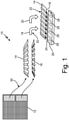
- FIG. 1 is an illustrated view of process flow 10 depicting large feedstock sheet 12, first feedstock piece 14, second feedstock piece 16, heat 18, compression 20, consolidated feedstock sheet 22 (with passages 24), header 26 (with channels 28), step 30, and step 32.
- Large feedstock sheet 12 is a single, large-scale feedstock sheet that is pre-fabricated via high temperature hot pressing.
- large feedstock sheet 12 can be formed via glass transfer molding or other forming processes.
- large feedstock sheet 12 includes glass-ceramic matrix composite material and a complex undulated geometry that can be made with standardized process equipment.
- large feedstock sheet 12 can include continuous or discontinuous fibers and/or reinforcements.
- First feedstock piece 14 and second feedstock piece 16 are two separate portions of large feedstock sheet 12.
- Heat 18 is an arrow representative of the application of thermal energy.
- Compression 20 is an arrow representative of the application of compression.
- Consolidated feedstock sheet 22 is a single composite feedstock sheet that includes first feedstock piece 14 and second feedstock piece 16 formed together.
- consolidated feedstock sheet 22 can represent a headered tube sheet for use in a heat exchanger.
- consolidated feedstock sheet 22 can represent a pre-consolidated feedstock sheet that is combined with additional materials and utilized in additional process steps to form a headered tube sheet.
- Passages 24 and channels 28 are passages or fluidic channels configured for the communication and transport of a fluid such as liquid or gas.
- header 26 is a header block of a heat exchanger or a heat exchanger assembly.
- Step 30 is a step in the process that includes sectioning or cutting pieces from large feedstock sheet 12 to produce first feedstock piece 14 and second feedstock piece 16. In another example, in place of or in addition to sectioning, step 30 can also include machining large feedstock sheet 12 into complex shapes or other varied geometrical shapes.
- Step 32 is another step in the process that includes applying heat 18 and compression 20 to first feedstock piece 14 and second feedstock piece 16 to form consolidated feedstock sheet 26.
- First feedstock piece 14 and second feedstock piece 16 are individual pieces sectioned or cut from large feedstock sheet 12 as shown by step 30.
- step 32 first feedstock piece 14 and second feedstock piece 16 become permanently joined to form consolidated feedstock sheet 22 with passages 24 formed between and by the joining of first feedstock piece 14 and second feedstock piece 16.
- heat 18 and compression 20 are applied to first feedstock piece 14 and second feedstock piece 16 in order to fuse first feedstock piece 14 and second feedstock piece 16 together to form consolidated feedstock sheet 22.
- consolidated feedstock sheet 22 can be connected physically and in fluid communication with header 26.
- Passages 24 extend through a plane of consolidated feedstock sheet 22.
- passages 24 are parallel to each other.
- passages 24 are in fluid communication with channels 28 of header 26.
- header 26 is shown as disconnected from consolidated feedstock sheet 22 for clarity.
- header 26 becomes attached to and mounted onto consolidated feedstock sheet 22.
- a second header with corresponding channels can be positioned on the far or opposite side of consolidate feedstock sheet 22 (such a second header block has been omitted from FIG. 1 for clarity).
- channels 28 are in fluid communication with passages 24 of consolidated feedstock sheet 22.
- channels 28 are shown with a U-shape configuration to direct fluid flow from one of passages 24 to another one of passages 24.
- channels 28 can include a straight shape so as to pass the fluid from one of passage 24, through header 26, and into another component connected to header 26.
- a method of forming a part includes fabricating a pre-consolidated feedstock sheet (e.g., large feedstock sheet 12).
- Fabricating large feedstock sheet 12 includes compression molding a glass-ceramic matrix composite material to include a pre-determined shape or shapes, which in this example can include bumps or corrugations. In other examples, the predetermine shape can include other complex geometries such as curves.
- Fabricating large feedstock sheet 12 can also include compression molding the glass-ceramic matrix composite material to form large feedstock sheet 12 with a pre-determined shape that includes embedded channels.
- compression molding the glass-ceramic matrix composite material includes hot pressing the glass-ceramic matrix composite material.
- the glass-ceramic matrix composite material can include ceramic fibers and/or glass matrix materials.
- Large feedstock sheet 12 is sectioned into a plurality of pieces of pre-consolidated feedstock sheet (e.g., first feedstock piece 14 and second feedstock piece 16).
- First feedstock piece 14 and second feedstock piece 16 are assembled with other materials such as one or more layers of tape (e.g., a non-woven material) and one or more mandrels to form a composite layup.
- the one or more layers of tape and one or more mandrels can include unidirectional fibers and glass powders in a 'green' or unconsolidated layup.
- a fabric e.g., a woven material
- the composite layup can include an assembly of various differently machined pieces of large feedstock sheet 12.
- the composite layup can include a pyramid shaped sack with various sized machined flat pieces of feedstock to form a more complex shape, with some of the feedstock pieces having holes or other features machined in the feedstock pieces.
- the composite layup is joined or consolidated by pressing the composite layup together to form a glass matrix composite part such as consolidated feedstock sheet 22.
- an orientation of the fibers e.g., parallel or orthogonal
- header 26 is formed by draping ceramic fiber fabric over a plurality of ceramic wound tubes, which is achieved by consolidating header 26 (via compression molding) with the glass matrix composite part. Header 26 is then joined to and in fluid communication with the glass matrix composite part to form a headered tube sheet heat exchanger. The tube sheet heat exchanger can then be ceramed to create the final GCMC part. In such a step, the ceraming is a crystallization step to order the previously amorphous structure of the glass matrix.
- large feedstock sheet 12 is pre-fabricated via high temperature and vacuum hot pressing.
- Large feedstock sheet 12 features complex undulated geometry (e.g., corrugations or embedded channels) that can be made with standardized process equipment and stored after processing.
- large feedstock sheet 12 is sectioned into multiple feedstock pieces.
- large feedstock sheet 12 is sectioned into first feedstock piece 14 and second feedstock piece 16 with various shapes and sizes as needed for processing more complex geometries with secondary hot pressing operations.
- Subsequent storage of the pre-consolidated feedstocks helps to maintain GCMC quality and repeatability compared to existing scenarios of storing unprocessed fiber and glass matrix material for processing into complex geometries to begin with.
- the process illustrated in process flow 10 involving the use of pre-consolidated sheets aids in subsequent complex geometry forming operation assembly via improved fiber placement and fiber orientation control, since the fiber architecture is fixed into the as-processed feedstock pieces (e.g., first feedstock piece 14 and second feedstock piece 16).
- process flow 10 lends itself to better, larger scale manufacturability and commercial viability. For example, utilizing the process illustrated in process flow 10 helps to address significantly high debulking ratios associated with joining a large number of layers, which can be particularly challenging with the formation of small-scale parts without the utilization of the process illustrated in process flow 10.
- Pre-consolidated feedstock elements such as first feedstock piece 14, second feedstock piece 16, and consolidated feedstock sheet 22 with prescribed geometries can be used in conjunction with other GCMC elements (e.g., additional un-consolidated fibers and/or glass powder, frit or other formats of granular dry materials) to encourage material flow and joining among all the feedstock layers and materials to form a final GCMC part with complex geometries.
- other GCMC elements e.g., additional un-consolidated fibers and/or glass powder, frit or other formats of granular dry materials
- FIG. 2 is a side exploded view of first assembly 34 and shows first feedstock piece 14A, second feedstock piece 16B, die tooling 36A and 36B, laminar composites 38A and 38B, and mandrels 40.
- character reference numerals with the letter “A” denote components positioned in the top half of the figure, while character reference numerals including the letter “B” denote components positioned in the bottom half of the figure. Accordingly, the description of the "A" set of components (i.e., 14A, 36A, and 38A) of FIG. 2 will also extend to cover the "B" set of character reference numerals (i.e., 16B, 36B, and 38B).
- FIG. 2 depicts die tooling utilized during step 32 shown in FIG. 1 .
- Die tooling 36A is a die for applying compression in the formation of composite GCMC parts.
- Laminar composite 38A is a laminated prepressed composite material.
- laminar composite 38A can be an unprocessed/unconsolidated tape or tapes.
- Mandrels 40 are cylindrical or tubular pieces of solid material such as graphite.
- first feedstock piece 14A is positioned between mandrels 40 and laminar composite 38A.
- Second feedstock piece 16B is positioned between mandrels 40 and laminar composite 38B.
- Die tooling 36A and die tooling 36B are positioned on the top and bottom, respectively of first assembly 34 (top and bottom as shown in FIG. 2 ).
- Laminar composite 38A is positioned between first feedstock sheet 14A and die tooling 36A.
- Mandrels 40 are disposed between first feedstock sheet 14A and second feedstock sheet 16B.
- Mandrels are also aligned along a parallel direction with corrugations or imbedded channels of first feedstock sheet 14A and second feedstock 16B.
- the order of laying of materials above mandrels 40 can be first feedstock sheet 14A, laminar composite 38A, and then die tooling 36A.
- first feedstock piece 14A can instead replace laminar composite 38A and the position of feedstock piece 14A can be replaced with one or more unprocessed/unconsolidated tapes (e.g., 'green' tapes).
- a laying order of materials upward from mandrels 40 would be a layer of unprocessed/unconsolidated tapes (in the positioned occupied by first feedstock sheet 14A as shown in FIG. 2 ), newly positioned first feedstock sheet 14A (in the position occupied by laminar composite 38A as shown in FIG. 2 ), and then die tooling 36A.
- This alternate example would also apply to the "B" set of components, in particular those of second feedstock sheet 16B, laminar composite 38A, and die tooling 36B.
- a layer of unprocessed/unconsolidated tapes can be added to first assembly 34 in between any of mandrels 40, first feedstock layer 14A, second feedstock layer 16B, laminar composites 38A and 38B, and die tooling 36A and 36B.
- a method of forming a glass-ceramic matrix composite part includes forming a consolidated feedstock material (see e.g., FIG. 1 , large feedstock sheet 12) and forming a consolidated glass-ceramic matrix composite complex part (see e.g., FIG. 1 , consolidated feedstock sheet 22).
- Forming large feedstock sheet 12 includes sourcing ceramic fiber and glass matrix materials that are unconsolidated. The unconsolidated ceramic fiber and glass matrix materials can be measured.
- measurements of the unconsolidated ceramic fiber and glass matrix materials can include measurements of fiber count (e.g., numeric quantity of fibers), fiber density (e.g., fiber quantity per unit volume), fiber distribution, weight (e.g., kilograms or pounds), size (e.g., centimeters or inches), and volume (e.g., cubic centimeters, liters, or cubic inches).
- the specifications of the unconsolidated ceramic fiber and glass matrix materials can be determined based on the measurement of the unconsolidated ceramic fiber and glass matrix materials.
- the specifications of the unconsolidated ceramic fiber and glass matrix materials can include volume fraction of fibers or other relationships between any of the fiber count, fiber density, fiber distribution, weight, size, and volume measurements.
- the specifications of the unconsolidated ceramic fiber and glass matrix materials can then be compared with predetermined values. Additionally, the measured unconsolidated fiber and glass matrix can be compared to the pieces/components of the consolidated feedstock material (see e.g., FIG. 1 , large feedstock sheet 12).
- the unconsolidated ceramic fiber and glass matrix materials are loaded into a first set of tooling. Heat and pressure are then applied by the first set of tooling to the ceramic fiber and glass matrix materials (i.e., the unconsolidated ceramic fiber and glass matrix materials) to form large feedstock sheet 12 (i.e., a consolidated feedstock material).
- large feedstock sheet 12 can be stored or placed into storage until it is retrieved to be used in the formation of a complex consolidated glass-ceramic matrix composite part.
- the consolidated feedstock material can be measured.
- the specifications of the consolidated feedstock material can be determined based on the measurement of the consolidated feedstock material.
- the specifications of the consolidated feedstock material can then be compared with predetermined values.
- Forming the consolidated glass-ceramic matrix composite complex part includes sectioning the consolidated feedstock material (e.g., large feedstock sheet 12, or starting with two or more separate feedstock pieces) to produce a plurality of consolidated feedstock material pieces (e.g., FIG. 1 , first feedstock sheet 14/14A and second feedstock sheet 16/16B).
- First feedstock sheet 14A and second feedstock sheet 16B i.e., the consolidated feedstock material pieces
- Heat e.g., thermal energy
- pressure then are applied to the consolidated feedstock material pieces to form the consolidated glass matrix composite complex part.
- the heat and pressure can be applied in a high vacuum environment or in an inert gas environment during pressing.
- die tooling applies compression (e.g., pressing) and/or thermal energy to first assembly 34 to for the consolidated glass matrix composite complex part.
- an inert gas can be flowed into first assembly 34 to expedite cooling of the part, die tooling, and hot press chamber.
- Post-processing and finishing steps can also be applied to the consolidated glass matrix composite complex part to form the final glass-ceramic matrix composite complex part.
- post-processing and/or finishing steps can include surface treatments (e.g., coatings, hardening, etc.), grinding, polishing, sanding, trimming, and other similar processes.
- first assembly 34 and the process illustrated by process flow 10
- the fibers and glass powder are more easily managed by the pre-formed shapes of first feedstock sheet 14, second feedstock sheet 16, and consolidated feedstock sheet 22 with intermediate complexities, which are loaded into the tooling (e.g., die tooling 36A and 38B) to form the final workpiece.
- FIG. 3 is a side assembled view of second assembly 42 and shows consolidated feedstock sheet 44 (with passages 46), first upper preformed block section 48 (with fibers 50), first lower preformed block section 52 (with fibers 54), second upper preformed block section 56, and second lower preformed block section 58.
- Second assembly 42 is a composite layup of materials including consolidated feedstock sheet 44, first upper preformed block section 48, first lower preformed block section 52, second upper preformed block section 56, and second lower preformed block section 58.
- Consolidated feedstock sheet 44 is a preformed sheet of feedstock material.
- consolidated feedstock sheet 44 is the consolidated feedstock piece resulting from the pressing of assembly 34 shown in FIG. 2 .
- Passages 46 are fluid channels or cylindrical openings.
- passages 46 are formed by mandrels 40 shown in FIG. 2 .
- First upper preformed block section 48 and first lower preformed block section 52 are preformed block sections of material that include fibers, glass matrix, and/or glass powder that are configured to flow during a joining step.
- fibers 50 and fibers 54 can include fibers or other GCMC materials.
- Second upper preformed block section 56 and second lower preformed block section 58 are preformed block sections of material that include fibers and/or glass powder that are configured to have reduced flowability during a joining step.
- Second assembly 42 is shown in an assembled and formed state.
- Consolidated feedstock sheet 44 is disposed between first upper preformed block section 48 and first lower preformed block section 52.
- Passages 46 are formed in and disposed through consolidated feedstock sheet 44.
- First upper preformed block section 48 is disposed between and in contact with consolidated feedstock sheet 44 and second upper preformed block section 56.
- Fibers 50 are disposed within and throughout first upper preformed block section 48.
- First lower preformed block section 52 is disposed between and in contact with consolidated feedstock sheet 44 and second lower preformed block section 58.
- Fibers 54 are disposed within and throughout first lower preformed block section 52.
- Second upper preformed block section 56 is disposed as a top layer of second assembly 42.
- Second lower preformed block section 58 is disposed as a bottom layer of second assembly 42.
- fibers 50 and 54 are shown as having an evenly spaced distribution pattern throughout first upper preformed block section 48 and first lower preformed block section, respectively.
- the corrugated shape of consolidated feedstock sheet 44 allows fibers 50 and 54 to self-assemble and remain in general alignment as all of the different layers are pressed together.
- material consistency thresholds e.g., fiber volume faction
- fibers 50 and 54 of assembly 42 are oriented such that material flow around passages 46 is encouraged.
- Such material flow during processing creates joining of pre-consolidated GCMC layer(s) (e.g., consolidated feedstock sheet 44), un-consolidated GCMC layers (e.g., first upper and lower preformed block sections 48 and 52 and second upper and lower preformed block sections 56 and 58), and embedded mandrels 40 (represented by passages 46 in FIG. 3 ) to form a complex geometry GCMC part (e.g., the workpiece that is formed by second assembly 42).
- the fiber and glass matrix GCMC material that is added for process flow is free to fill in unconsolidated regions and improves local and global material properties by reducing the areas without fiber reinforcement and matrix porosity.
- the processes and assemblies discussed herein provide repeatable quality GCMC for complex geometry parts, by providing a method to lock fiber orientation, matrix density, and fiber/matrix distributions by starting from consistent quality feedstock to assemble more complex geometries. Such processes and assemblies also reduce the risks associated with complex geometry fiber preform lay-up and reduce the possibilities of significant fiber misalignments, loss of fiber during assembly, matrix maldistribution, and loss of matrix during assembly.
- the processes and assemblies of the disclosure provide for easier joining of unconsolidated and/or pre-consolidated GCMC parts.
- the processes and assemblies of the disclosure also allow for easier GCMC laminate mixing and matching with different fiber orientations.
- the processes and assemblies of the disclosure provide opportunities for improved GCMC assembly design space and realizable cost reductions.
- a method of forming a part includes forming a glass-ceramic matrix composite material to form a pre-consolidated feedstock sheet with a pre-determined shape.
- the pre-consolidated feedstock sheet is sectioned into a first piece of pre-consolidated feedstock sheet and a second piece of pre-consolidated feedstock sheet.
- the first piece of pre-consolidated feedstock sheet and a second piece of pre-consolidated feedstock sheet are assembled with a second piece of pre-consolidated feedstock sheet to form a composite layup.
- the first piece of pre-consolidated feedstock sheet and the second piece of pre-consolidated feedstock sheet are joined by compressing the composite layup to form a glass-ceramic matrix composite part.
- the method of the preceding paragraph can optionally include, additionally and/or alternatively, any one or more of the following steps, features, configurations, and/or additional components.
- One of the plurality of pieces of pre-consolidated feedstock sheet can be assembled with at least one of a tape and a mandrel.
- the pre-determined shape of the pre-consolidated feedstock sheet can include embedded channels.
- Forming the glass-ceramic matrix composite material can comprise at least one of heating, inert gas hot pressing, and/or vacuum hot pressing the glass-ceramic matrix composite material.
- the pre-consolidated feedstock sheet comprises ceramic fibers, and the method further comprising maintaining an orientation of the ceramic fibers during the steps of assembling and joining.
- a header block can be formed by pushing a ceramic fiber fabric with glass matrix down over a plurality of ceramic fiber and glass matrix wound tubes; and/or the header block can be formed to the glass matrix composite part to form a headered tube sheet heat exchanger.
- Joining of feedstock header blocks to tube sheet can comprise consolidating the header block with the glass matrix composite part.
- Joining the header block to the glass matrix composite part can comprise ceraming the header block and/or the glass matrix composite part to transform the glass matrix into a glass-ceramic matrix.
- the header block can be connected to and/or in fluid communication with the glass matrix composite part.
- a method of forming a glass-ceramic matrix composite part includes forming a consolidated feedstock material and forming a consolidated glass-ceramic matrix composite complex part.
- Forming a consolidated feedstock material includes sourcing a ceramic fiber and a glass matrix material that are unconsolidated. The unconsolidated ceramic fiber and glass matrix materials are loaded into a first tooling. Heat and pressure are applied to the unconsolidated ceramic fiber and glass matrix materials to form a consolidated feedstock material.
- Forming the consolidated glass-ceramic matrix composite complex part includes sectioning the consolidated feedstock material to produce a plurality of consolidated feedstock material pieces. The plurality of consolidated feedstock material pieces is assembled into a composite layup. Heat and pressure are then applied to the composite layup to fuse the consolidated feedstock material pieces and form the consolidated glass-ceramic matrix composite complex part.
- the method of the preceding paragraph can optionally include, additionally and/or alternatively, any one or more of the following steps, features, configurations, and/or additional components.
- Unconsolidated ceramic fiber and/or glass matrix materials can be measured, specifications of the unconsolidated ceramic fiber and/or glass matrix materials can be determined based on the measurement of the unconsolidated ceramic fiber and glass matrix materials, and/or the specifications of the unconsolidated ceramic fiber and glass matrix materials can be compared with predetermined values.
- unconsolidated ceramic fiber and glass matrix materials can comprise volume fraction of fibers, fiber count, fiber density, fiber distribution, weight, size, and volume of the unconsolidated ceramic fiber and glass matrix materials.
- Consolidated feedstock material can be measured, specifications of the consolidated feedstock material can be determined based on the measurement of the consolidated feedstock material, and/or the specifications of the consolidated feedstock material can be compared with predetermined values.
- Specifications of the consolidated feedstock material can comprise volume fraction of fibers, fiber count, fiber density, fiber distribution, weight, size, and volume of the consolidated feedstock material.
- a finishing operation can be applied to the consolidated glass matrix composite complex part to form the consolidated glass-ceramic matrix composite complex part.
- the finishing operation can comprise at least one of surface treatments, grinding, polishing, sanding, and trimming.
- a portion of the consolidated feedstock material can be machined to produce a shaped consolidated feedstock material piece.
- a shape of the shaped consolidated feedstock material piece can comprise at least one of a holed, a bumped, a corrugated, and a curved shape.
Landscapes
- Chemical & Material Sciences (AREA)
- Engineering & Computer Science (AREA)
- Materials Engineering (AREA)
- Organic Chemistry (AREA)
- Manufacturing & Machinery (AREA)
- Dispersion Chemistry (AREA)
- Producing Shaped Articles From Materials (AREA)
- Laminated Bodies (AREA)
Abstract
Description
- This invention was made with government support under Contract No. DE-EE0008318 awarded by United States Department of Energy. The government has certain rights in the invention.
- This disclosure relates generally to glass-ceramic matrix composites ("GCMCs") and more particularly to the processing and formation of a GCMC part.
- In formation of GCMC's, one of the technical challenges is to rapidly and fully consolidate high temperature molten glass into ceramic fibers to form GCMC parts. Additionally, complex geometries of the GCMC part can create areas with defects due to the challenge of maintaining fiber orientations and matrix density during fiber preform layup into dies or molds.
- A method of forming a part includes forming a glass-ceramic matrix composite material to form a pre-consolidated feedstock sheet with a pre-determined shape. The pre-consolidated feedstock sheet is sectioned into a first piece of pre-consolidated feedstock sheet and a second piece of pre-consolidated feedstock sheet. The first piece of pre-consolidated feedstock sheet and a second piece of pre-consolidated feedstock sheet are assembled with a second piece of pre-consolidated feedstock sheet to form a composite layup. The first piece of pre-consolidated feedstock sheet and the second piece of pre-consolidated feedstock sheet are joined by compressing the composite layup to form a glass-ceramic matrix composite part.
- A method of forming a glass-ceramic matrix composite part includes forming a consolidated feedstock material and forming a consolidated glass-ceramic matrix composite complex part. Forming a consolidated feedstock material includes sourcing a ceramic fiber and a glass matrix material that are unconsolidated. The unconsolidated ceramic fiber and glass matrix materials are loaded into a first tooling. Heat and pressure are applied to the unconsolidated ceramic fiber and glass matrix materials to form a consolidated feedstock material. Forming the consolidated glass-ceramic matrix composite complex part includes sectioning the consolidated feedstock material to produce a plurality of consolidated feedstock material pieces. The plurality of consolidated feedstock material pieces is assembled into a composite layup. Heat and pressure are then applied to the composite layup to fuse the consolidated feedstock material pieces and form the consolidated glass-ceramic matrix composite complex part.
- The present summary is provided only by way of example, and not limitation. Other aspects of the present disclosure will be appreciated in view of the entirety of the present disclosure, including the entire text, claims, and accompanying figures.
-
-
FIG. 1 is a process illustration of a method of forming and joining glass-ceramic matrix composite feedstock. -
FIG. 2 is a side exploded view of a first feedstock assembly before the feedstock assembly is joined. -
FIG. 3 is a side assembled view of second feedstock assembly after the second assembly is joined. - While the above-identified figures set forth one or more embodiments of the present disclosure, other embodiments are also contemplated, as noted in the discussion. In all cases, this disclosure presents by way of representation and not limitation. It should be understood that numerous other modifications and embodiments can be devised by those skilled in the art, which fall within the scope and spirit of the principles of the disclosure. The figures may not be drawn to scale, and applications and embodiments of the present disclosure may include features and components not specifically shown in the drawings.
- This disclosure presents a process of forming a GCMC workpiece by pre-consolidating GCMC material(s) in a first compression molding step to produce shaped feedstock parts, then combining one or more feedstock parts into an assembly. This assembly of parts is joined together with secondary compression molding operations to form a final GCMC part with complex geometries. In some embodiments, other methods of forming such as glass transfer molding can alternatively or additionally be used.
- An example application of this disclosure is the fabrication of feedstock tube sheets with embedded channels and feedstock blocks for headers that are joined together to form headered tube sheets for high temperature heat exchangers. The disclosure can be used to fabricate corrugated tube sheet feedstock that is then sectioned and formed into heat exchanger tube sheet elements. To do this, one can pre-consolidate GCMC layers, then one can pre-consolidate that position and join the tubes together in a tube sheet.
-
FIG. 1 is an illustrated view ofprocess flow 10 depictinglarge feedstock sheet 12,first feedstock piece 14,second feedstock piece 16,heat 18,compression 20, consolidated feedstock sheet 22 (with passages 24), header 26 (with channels 28),step 30, andstep 32. -
Large feedstock sheet 12 is a single, large-scale feedstock sheet that is pre-fabricated via high temperature hot pressing. In another example,large feedstock sheet 12 can be formed via glass transfer molding or other forming processes. In this example,large feedstock sheet 12 includes glass-ceramic matrix composite material and a complex undulated geometry that can be made with standardized process equipment. In one example,large feedstock sheet 12 can include continuous or discontinuous fibers and/or reinforcements.First feedstock piece 14 andsecond feedstock piece 16 are two separate portions oflarge feedstock sheet 12.Heat 18 is an arrow representative of the application of thermal energy.Compression 20 is an arrow representative of the application of compression. - Consolidated
feedstock sheet 22 is a single composite feedstock sheet that includesfirst feedstock piece 14 andsecond feedstock piece 16 formed together. In one example, consolidatedfeedstock sheet 22 can represent a headered tube sheet for use in a heat exchanger. In another example, consolidatedfeedstock sheet 22 can represent a pre-consolidated feedstock sheet that is combined with additional materials and utilized in additional process steps to form a headered tube sheet.Passages 24 andchannels 28 are passages or fluidic channels configured for the communication and transport of a fluid such as liquid or gas. In this example,header 26 is a header block of a heat exchanger or a heat exchanger assembly. -
Step 30 is a step in the process that includes sectioning or cutting pieces fromlarge feedstock sheet 12 to producefirst feedstock piece 14 andsecond feedstock piece 16. In another example, in place of or in addition to sectioning,step 30 can also include machininglarge feedstock sheet 12 into complex shapes or other varied geometrical shapes.Step 32 is another step in the process that includes applyingheat 18 andcompression 20 tofirst feedstock piece 14 andsecond feedstock piece 16 to form consolidatedfeedstock sheet 26. -
First feedstock piece 14 andsecond feedstock piece 16 are individual pieces sectioned or cut fromlarge feedstock sheet 12 as shown bystep 30. Instep 32,first feedstock piece 14 andsecond feedstock piece 16 become permanently joined to form consolidatedfeedstock sheet 22 withpassages 24 formed between and by the joining offirst feedstock piece 14 andsecond feedstock piece 16. Duringstep 32,heat 18 andcompression 20 are applied tofirst feedstock piece 14 andsecond feedstock piece 16 in order to fusefirst feedstock piece 14 andsecond feedstock piece 16 together to form consolidatedfeedstock sheet 22. In this example, consolidatedfeedstock sheet 22 can be connected physically and in fluid communication withheader 26. -
Passages 24 extend through a plane of consolidatedfeedstock sheet 22. In this example,passages 24 are parallel to each other. Upon assembly ofheader 26 to consolidatedfeedstock sheet 22,passages 24 are in fluid communication withchannels 28 ofheader 26. Here,header 26 is shown as disconnected from consolidatedfeedstock sheet 22 for clarity. In an assembled state,header 26 becomes attached to and mounted onto consolidatedfeedstock sheet 22. In another example, a second header with corresponding channels can be positioned on the far or opposite side of consolidate feedstock sheet 22 (such a second header block has been omitted fromFIG. 1 for clarity). In an assembled state,channels 28 are in fluid communication withpassages 24 of consolidatedfeedstock sheet 22. Here,channels 28 are shown with a U-shape configuration to direct fluid flow from one ofpassages 24 to another one ofpassages 24. In another embodiment,channels 28 can include a straight shape so as to pass the fluid from one ofpassage 24, throughheader 26, and into another component connected toheader 26. - In one example, a method of forming a part includes fabricating a pre-consolidated feedstock sheet (e.g., large feedstock sheet 12). Fabricating
large feedstock sheet 12 includes compression molding a glass-ceramic matrix composite material to include a pre-determined shape or shapes, which in this example can include bumps or corrugations. In other examples, the predetermine shape can include other complex geometries such as curves. Fabricatinglarge feedstock sheet 12 can also include compression molding the glass-ceramic matrix composite material to formlarge feedstock sheet 12 with a pre-determined shape that includes embedded channels. In this example, compression molding the glass-ceramic matrix composite material includes hot pressing the glass-ceramic matrix composite material. Here, the glass-ceramic matrix composite material can include ceramic fibers and/or glass matrix materials. -
Large feedstock sheet 12 is sectioned into a plurality of pieces of pre-consolidated feedstock sheet (e.g.,first feedstock piece 14 and second feedstock piece 16).First feedstock piece 14 andsecond feedstock piece 16 are assembled with other materials such as one or more layers of tape (e.g., a non-woven material) and one or more mandrels to form a composite layup. In one example, the one or more layers of tape and one or more mandrels can include unidirectional fibers and glass powders in a 'green' or unconsolidated layup. In another example, a fabric (e.g., a woven material) can be used in place of an/or in combination with the one or more layers of tape. In another example, the composite layup can include an assembly of various differently machined pieces oflarge feedstock sheet 12. In such an example, the composite layup can include a pyramid shaped sack with various sized machined flat pieces of feedstock to form a more complex shape, with some of the feedstock pieces having holes or other features machined in the feedstock pieces. The composite layup is joined or consolidated by pressing the composite layup together to form a glass matrix composite part such asconsolidated feedstock sheet 22. During the step of assembling and joining, an orientation of the fibers (e.g., parallel or orthogonal) is maintained. - Additionally,
header 26 is formed by draping ceramic fiber fabric over a plurality of ceramic wound tubes, which is achieved by consolidating header 26 (via compression molding) with the glass matrix composite part.Header 26 is then joined to and in fluid communication with the glass matrix composite part to form a headered tube sheet heat exchanger. The tube sheet heat exchanger can then be ceramed to create the final GCMC part. In such a step, the ceraming is a crystallization step to order the previously amorphous structure of the glass matrix. - Here,
large feedstock sheet 12 is pre-fabricated via high temperature and vacuum hot pressing.Large feedstock sheet 12 features complex undulated geometry (e.g., corrugations or embedded channels) that can be made with standardized process equipment and stored after processing. Next,large feedstock sheet 12 is sectioned into multiple feedstock pieces. In the illustrated embodiment, for example,large feedstock sheet 12 is sectioned intofirst feedstock piece 14 andsecond feedstock piece 16 with various shapes and sizes as needed for processing more complex geometries with secondary hot pressing operations. Subsequent storage of the pre-consolidated feedstocks (e.g.,first feedstock piece 14 and second feedstock piece 16) helps to maintain GCMC quality and repeatability compared to existing scenarios of storing unprocessed fiber and glass matrix material for processing into complex geometries to begin with. Also, the process illustrated in process flow 10 involving the use of pre-consolidated sheets (e.g.,first feedstock piece 14 and second feedstock piece 16) aids in subsequent complex geometry forming operation assembly via improved fiber placement and fiber orientation control, since the fiber architecture is fixed into the as-processed feedstock pieces (e.g.,first feedstock piece 14 and second feedstock piece 16). - The process illustrated in
process flow 10 lends itself to better, larger scale manufacturability and commercial viability. For example, utilizing the process illustrated inprocess flow 10 helps to address significantly high debulking ratios associated with joining a large number of layers, which can be particularly challenging with the formation of small-scale parts without the utilization of the process illustrated inprocess flow 10. - Pre-consolidated feedstock elements such as
first feedstock piece 14,second feedstock piece 16, andconsolidated feedstock sheet 22 with prescribed geometries can be used in conjunction with other GCMC elements (e.g., additional un-consolidated fibers and/or glass powder, frit or other formats of granular dry materials) to encourage material flow and joining among all the feedstock layers and materials to form a final GCMC part with complex geometries. -
FIG. 2 is a side exploded view offirst assembly 34 and showsfirst feedstock piece 14A,second feedstock piece 16B, dietooling laminar composites FIG. 2 , character reference numerals with the letter "A" denote components positioned in the top half of the figure, while character reference numerals including the letter "B" denote components positioned in the bottom half of the figure. Accordingly, the description of the "A" set of components (i.e., 14A, 36A, and 38A) ofFIG. 2 will also extend to cover the "B" set of character reference numerals (i.e., 16B, 36B, and 38B). In one example,FIG. 2 depicts die tooling utilized duringstep 32 shown inFIG. 1 . - Die tooling 36A is a die for applying compression in the formation of composite GCMC parts. Laminar composite 38A is a laminated prepressed composite material. In one example, laminar composite 38A can be an unprocessed/unconsolidated tape or tapes.
Mandrels 40 are cylindrical or tubular pieces of solid material such as graphite. As shown inFIG. 2 ,first feedstock piece 14A is positioned betweenmandrels 40 and laminar composite 38A.Second feedstock piece 16B is positioned betweenmandrels 40 and laminar composite 38B. Dietooling 36A and dietooling 36B are positioned on the top and bottom, respectively of first assembly 34 (top and bottom as shown inFIG. 2 ). Laminar composite 38A is positioned betweenfirst feedstock sheet 14A and dietooling 36A.Mandrels 40 are disposed betweenfirst feedstock sheet 14A andsecond feedstock sheet 16B. Mandrels are also aligned along a parallel direction with corrugations or imbedded channels offirst feedstock sheet 14A andsecond feedstock 16B. - As shown in
FIG. 2 , the order of laying of materials abovemandrels 40 can befirst feedstock sheet 14A, laminar composite 38A, and then dietooling 36A. In another example,first feedstock piece 14A can instead replace laminar composite 38A and the position offeedstock piece 14A can be replaced with one or more unprocessed/unconsolidated tapes (e.g., 'green' tapes). In such an example, a laying order of materials upward frommandrels 40 would be a layer of unprocessed/unconsolidated tapes (in the positioned occupied byfirst feedstock sheet 14A as shown inFIG. 2 ), newly positionedfirst feedstock sheet 14A (in the position occupied by laminar composite 38A as shown inFIG. 2 ), and then dietooling 36A. This alternate example would also apply to the "B" set of components, in particular those ofsecond feedstock sheet 16B, laminar composite 38A, and dietooling 36B. - In yet another example, a layer of unprocessed/unconsolidated tapes can be added to
first assembly 34 in between any ofmandrels 40,first feedstock layer 14A,second feedstock layer 16B,laminar composites tooling - In one example, a method of forming a glass-ceramic matrix composite part includes forming a consolidated feedstock material (see e.g.,
FIG. 1 , large feedstock sheet 12) and forming a consolidated glass-ceramic matrix composite complex part (see e.g.,FIG. 1 , consolidated feedstock sheet 22). Forminglarge feedstock sheet 12 includes sourcing ceramic fiber and glass matrix materials that are unconsolidated. The unconsolidated ceramic fiber and glass matrix materials can be measured. In this example, measurements of the unconsolidated ceramic fiber and glass matrix materials can include measurements of fiber count (e.g., numeric quantity of fibers), fiber density (e.g., fiber quantity per unit volume), fiber distribution, weight (e.g., kilograms or pounds), size (e.g., centimeters or inches), and volume (e.g., cubic centimeters, liters, or cubic inches). The specifications of the unconsolidated ceramic fiber and glass matrix materials can be determined based on the measurement of the unconsolidated ceramic fiber and glass matrix materials. In this example, the specifications of the unconsolidated ceramic fiber and glass matrix materials can include volume fraction of fibers or other relationships between any of the fiber count, fiber density, fiber distribution, weight, size, and volume measurements. The specifications of the unconsolidated ceramic fiber and glass matrix materials can then be compared with predetermined values. Additionally, the measured unconsolidated fiber and glass matrix can be compared to the pieces/components of the consolidated feedstock material (see e.g.,FIG. 1 , large feedstock sheet 12). - The unconsolidated ceramic fiber and glass matrix materials are loaded into a first set of tooling. Heat and pressure are then applied by the first set of tooling to the ceramic fiber and glass matrix materials (i.e., the unconsolidated ceramic fiber and glass matrix materials) to form large feedstock sheet 12 (i.e., a consolidated feedstock material). Once formed,
large feedstock sheet 12 can be stored or placed into storage until it is retrieved to be used in the formation of a complex consolidated glass-ceramic matrix composite part. In one example, the consolidated feedstock material can be measured. The specifications of the consolidated feedstock material can be determined based on the measurement of the consolidated feedstock material. The specifications of the consolidated feedstock material can then be compared with predetermined values. - Forming the consolidated glass-ceramic matrix composite complex part includes sectioning the consolidated feedstock material (e.g.,
large feedstock sheet 12, or starting with two or more separate feedstock pieces) to produce a plurality of consolidated feedstock material pieces (e.g.,FIG. 1 ,first feedstock sheet 14/14A andsecond feedstock sheet 16/16B).First feedstock sheet 14A andsecond feedstock sheet 16B (i.e., the consolidated feedstock material pieces) are loaded into a second set of tooling (e.g., dietooling first assembly 34 to for the consolidated glass matrix composite complex part. After this pressing stage, an inert gas can be flowed intofirst assembly 34 to expedite cooling of the part, die tooling, and hot press chamber. Post-processing and finishing steps can also be applied to the consolidated glass matrix composite complex part to form the final glass-ceramic matrix composite complex part. In one example, post-processing and/or finishing steps can include surface treatments (e.g., coatings, hardening, etc.), grinding, polishing, sanding, trimming, and other similar processes. - With existing processes, building a complex structure by laying up fibers in particular positions and orientations can be challenging. Likewise, managing glass powder so that the glass powder is distributed evenly though all of the complex curvatures and inner-tow/intra-tow spacing of the fibers, (e.g., for heat exchangers with geometries with thin walls or for high-temp bladed vane applications with curvature). Here with the use of
first assembly 34 and the process illustrated byprocess flow 10, the fibers and glass powder are more easily managed by the pre-formed shapes offirst feedstock sheet 14,second feedstock sheet 16, andconsolidated feedstock sheet 22 with intermediate complexities, which are loaded into the tooling (e.g., dietooling -
FIG. 3 is a side assembled view ofsecond assembly 42 and shows consolidated feedstock sheet 44 (with passages 46), first upper preformed block section 48 (with fibers 50), first lower preformed block section 52 (with fibers 54), second upper preformedblock section 56, and second lower preformedblock section 58. -
Second assembly 42 is a composite layup of materials includingconsolidated feedstock sheet 44, first upper preformedblock section 48, first lower preformedblock section 52, second upper preformedblock section 56, and second lower preformedblock section 58.Consolidated feedstock sheet 44 is a preformed sheet of feedstock material. In this example,consolidated feedstock sheet 44 is the consolidated feedstock piece resulting from the pressing ofassembly 34 shown inFIG. 2 . -
Passages 46 are fluid channels or cylindrical openings. In this example,passages 46 are formed bymandrels 40 shown inFIG. 2 . First upper preformedblock section 48 and first lower preformedblock section 52 are preformed block sections of material that include fibers, glass matrix, and/or glass powder that are configured to flow during a joining step. In this example,fibers 50 andfibers 54 can include fibers or other GCMC materials. Second upperpreformed block section 56 and second lower preformedblock section 58 are preformed block sections of material that include fibers and/or glass powder that are configured to have reduced flowability during a joining step. -
Second assembly 42 is shown in an assembled and formed state.Consolidated feedstock sheet 44 is disposed between first upper preformedblock section 48 and first lower preformedblock section 52.Passages 46 are formed in and disposed throughconsolidated feedstock sheet 44. First upper preformedblock section 48 is disposed between and in contact withconsolidated feedstock sheet 44 and second upper preformedblock section 56.Fibers 50 are disposed within and throughout first upper preformedblock section 48. First lower preformedblock section 52 is disposed between and in contact withconsolidated feedstock sheet 44 and second lower preformedblock section 58.Fibers 54 are disposed within and throughout first lower preformedblock section 52. Second upperpreformed block section 56 is disposed as a top layer ofsecond assembly 42. Second lower preformedblock section 58 is disposed as a bottom layer ofsecond assembly 42. - Here,
fibers block section 48 and first lower preformed block section, respectively. During the pressing stages of the forming process, the corrugated shape ofconsolidated feedstock sheet 44 allowsfibers - In this example,
fibers assembly 42 are oriented such that material flow aroundpassages 46 is encouraged. Such material flow during processing creates joining of pre-consolidated GCMC layer(s) (e.g., consolidated feedstock sheet 44), un-consolidated GCMC layers (e.g., first upper and lower preformedblock sections block sections 56 and 58), and embedded mandrels 40 (represented bypassages 46 inFIG. 3 ) to form a complex geometry GCMC part (e.g., the workpiece that is formed by second assembly 42). Also, the fiber and glass matrix GCMC material that is added for process flow is free to fill in unconsolidated regions and improves local and global material properties by reducing the areas without fiber reinforcement and matrix porosity. - The processes and assemblies discussed herein provide repeatable quality GCMC for complex geometry parts, by providing a method to lock fiber orientation, matrix density, and fiber/matrix distributions by starting from consistent quality feedstock to assemble more complex geometries. Such processes and assemblies also reduce the risks associated with complex geometry fiber preform lay-up and reduce the possibilities of significant fiber misalignments, loss of fiber during assembly, matrix maldistribution, and loss of matrix during assembly. The processes and assemblies of the disclosure provide for easier joining of unconsolidated and/or pre-consolidated GCMC parts. The processes and assemblies of the disclosure also allow for easier GCMC laminate mixing and matching with different fiber orientations. The processes and assemblies of the disclosure provide opportunities for improved GCMC assembly design space and realizable cost reductions.
- A method of forming a part includes forming a glass-ceramic matrix composite material to form a pre-consolidated feedstock sheet with a pre-determined shape. The pre-consolidated feedstock sheet is sectioned into a first piece of pre-consolidated feedstock sheet and a second piece of pre-consolidated feedstock sheet. The first piece of pre-consolidated feedstock sheet and a second piece of pre-consolidated feedstock sheet are assembled with a second piece of pre-consolidated feedstock sheet to form a composite layup. The first piece of pre-consolidated feedstock sheet and the second piece of pre-consolidated feedstock sheet are joined by compressing the composite layup to form a glass-ceramic matrix composite part.
- The method of the preceding paragraph can optionally include, additionally and/or alternatively, any one or more of the following steps, features, configurations, and/or additional components.
- One of the plurality of pieces of pre-consolidated feedstock sheet can be assembled with at least one of a tape and a mandrel.
- The pre-determined shape of the pre-consolidated feedstock sheet can include embedded channels.
- Forming the glass-ceramic matrix composite material can comprise at least one of heating, inert gas hot pressing, and/or vacuum hot pressing the glass-ceramic matrix composite material.
- The pre-consolidated feedstock sheet comprises ceramic fibers, and the method further comprising maintaining an orientation of the ceramic fibers during the steps of assembling and joining.
- A header block can be formed by pushing a ceramic fiber fabric with glass matrix down over a plurality of ceramic fiber and glass matrix wound tubes; and/or the header block can be formed to the glass matrix composite part to form a headered tube sheet heat exchanger.
- Joining of feedstock header blocks to tube sheet can comprise consolidating the header block with the glass matrix composite part.
- Joining the header block to the glass matrix composite part can comprise ceraming the header block and/or the glass matrix composite part to transform the glass matrix into a glass-ceramic matrix.
- The header block can be connected to and/or in fluid communication with the glass matrix composite part.
- A method of forming a glass-ceramic matrix composite part includes forming a consolidated feedstock material and forming a consolidated glass-ceramic matrix composite complex part. Forming a consolidated feedstock material includes sourcing a ceramic fiber and a glass matrix material that are unconsolidated. The unconsolidated ceramic fiber and glass matrix materials are loaded into a first tooling. Heat and pressure are applied to the unconsolidated ceramic fiber and glass matrix materials to form a consolidated feedstock material. Forming the consolidated glass-ceramic matrix composite complex part includes sectioning the consolidated feedstock material to produce a plurality of consolidated feedstock material pieces. The plurality of consolidated feedstock material pieces is assembled into a composite layup. Heat and pressure are then applied to the composite layup to fuse the consolidated feedstock material pieces and form the consolidated glass-ceramic matrix composite complex part.
- The method of the preceding paragraph can optionally include, additionally and/or alternatively, any one or more of the following steps, features, configurations, and/or additional components.
- Unconsolidated ceramic fiber and/or glass matrix materials can be measured, specifications of the unconsolidated ceramic fiber and/or glass matrix materials can be determined based on the measurement of the unconsolidated ceramic fiber and glass matrix materials, and/or the specifications of the unconsolidated ceramic fiber and glass matrix materials can be compared with predetermined values.
- Specifications of the unconsolidated ceramic fiber and glass matrix materials can comprise volume fraction of fibers, fiber count, fiber density, fiber distribution, weight, size, and volume of the unconsolidated ceramic fiber and glass matrix materials.
- Consolidated feedstock material can be measured, specifications of the consolidated feedstock material can be determined based on the measurement of the consolidated feedstock material, and/or the specifications of the consolidated feedstock material can be compared with predetermined values.
- Specifications of the consolidated feedstock material can comprise volume fraction of fibers, fiber count, fiber density, fiber distribution, weight, size, and volume of the consolidated feedstock material.
- A finishing operation can be applied to the consolidated glass matrix composite complex part to form the consolidated glass-ceramic matrix composite complex part.
- The finishing operation can comprise at least one of surface treatments, grinding, polishing, sanding, and trimming.
- A portion of the consolidated feedstock material can be machined to produce a shaped consolidated feedstock material piece.
- A shape of the shaped consolidated feedstock material piece can comprise at least one of a holed, a bumped, a corrugated, and a curved shape.
- While the invention has been described with reference to an exemplary embodiment(s), it will be understood by those skilled in the art that various changes may be made and equivalents may be substituted for elements thereof without departing from the scope of the invention. In addition, many modifications may be made to adapt a particular situation or material to the teachings of the invention without departing from the essential scope thereof. Therefore, it is intended that the invention not be limited to the particular embodiment(s) disclosed, but that the invention will include all embodiments falling within the scope of the appended claims.
Claims (15)
- A method of forming a part, the method comprising:forming a glass-ceramic matrix composite material into a pre-consolidated feedstock sheet (22) with a pre-determined shape;sectioning the pre-consolidated feedstock sheet (22) into a first piece of pre-consolidated feedstock sheet and a second piece of pre-consolidated feedstock sheet;assembling the first piece of pre-consolidated feedstock sheet and the second piece of pre-consolidated feedstock sheet to form a composite layup; andjoining the first piece of pre-consolidated feedstock sheet and the second piece of pre-consolidated feedstock sheet by heating and compressing the composite layup to form a glass-ceramic matrix composite part.
- The method of claim 1, wherein assembling the first piece of pre-consolidated feedstock sheet and the second piece of pre-consolidated feedstock sheet comprises assembling the first piece of pre-consolidated feedstock sheet and the second piece of pre-consolidated feedstock sheet with at least one of a tape and a mandrel.
- The method of claim 1 or 2, wherein the pre-determined shape of the pre-consolidated feedstock sheet includes embedded channels.
- The method of any preceding claim, wherein forming the glass-ceramic matrix composite material comprises at least one inert gas hot pressing and vacuum hot pressing the glass-ceramic matrix composite material.
- The method of any preceding claim, wherein the pre-consolidated feedstock sheet comprises ceramic fibers, and the method further comprising maintaining an orientation of the ceramic fibers during the steps of assembling and joining.
- The method of any preceding claim, further comprising:forming a header block by pushing a ceramic fiber fabric with glass matrix down over a plurality of ceramic fiber and glass matrix wound tubes; andjoining the header block to the glass matrix composite part to form a headered tube sheet heat exchanger.
- The method of claim 6, wherein joining the header block to the glass matrix composite part comprises consolidating the header block with the glass matrix composite part, or wherein joining the header block to the glass matrix composite part comprises ceraming the header block and the glass matrix composite part to transform the glass matrix into a glass-ceramic matrix.
- The method of claim 6, wherein the header block is connected to and in fluid communication with the glass matrix composite part.
- A method of forming a glass-ceramic matrix composite part, the method comprising:forming a consolidated feedstock material, wherein forming the consolidated feedstock material comprises:sourcing a ceramic fiber and a glass matrix material that are unconsolidated;loading the unconsolidated ceramic fiber and glass matrix materials into a first tooling; andapplying heat and pressure to the unconsolidated ceramic fiber and glass matrix materials to form a consolidated feedstock material; andforming a consolidated glass-ceramic matrix composite part, wherein forming the consolidated glass-ceramic matrix composite part comprises:sectioning the consolidated feedstock material to produce a plurality of consolidated feedstock material pieces;assembling the plurality of consolidated feedstock material pieces into a composite layup; andapplying heat and pressure to the composite layup to fuse the consolidated feedstock material pieces and form the consolidated glass-ceramic matrix composite part with a complex shape.
- The method of claim 9, further comprising:measuring the unconsolidated ceramic fiber and glass matrix materials;determining specifications of the unconsolidated ceramic fiber and glass matrix materials based on the measurement of the unconsolidated ceramic fiber and glass matrix materials; andcompare the specifications of the unconsolidated ceramic fiber and glass matrix materials with predetermined values.
- The method of claim 10, wherein the specifications of the unconsolidated ceramic fiber and glass matrix materials comprise volume fraction of fibers, fiber count, fiber density, fiber distribution, weight, size, and volume of the unconsolidated ceramic fiber and glass matrix materials.
- The method of any of claims 9 to 11, further comprising:measuring the consolidated feedstock material;determining specifications of the consolidated feedstock material based on the measurement of the consolidated feedstock material; andcompare the specifications of the consolidated feedstock material with predetermined values.
- The method of claim 12, wherein the specifications of the consolidated feedstock material comprise volume fraction of fibers, fiber count, fiber density, fiber distribution, weight, size, and volume of the consolidated feedstock material.
- The method of any of claims 9 to 13, further comprising applying a finishing operation to the consolidated glass matrix composite part to form the consolidated glass-ceramic matrix composite part, and optionally wherein the finishing operation comprises at least one of surface treatments, grinding, polishing, sanding, and trimming.
- The method of any of claims 9 to 14, wherein sectioning the consolidated feedstock material comprises machining a portion of the consolidated feedstock material to produce a shaped consolidated feedstock material piece, and optionally wherein a shape of the shaped consolidated feedstock material piece comprises at least one of a holed, a bumped, a corrugated, and a curved shape.
Applications Claiming Priority (1)
| Application Number | Priority Date | Filing Date | Title |
|---|---|---|---|
| US17/012,351 US12024458B2 (en) | 2020-09-04 | 2020-09-04 | Glass-ceramic matrix composite feedstock and forming |
Publications (1)
| Publication Number | Publication Date |
|---|---|
| EP3964486A1 true EP3964486A1 (en) | 2022-03-09 |
Family
ID=76999611
Family Applications (1)
| Application Number | Title | Priority Date | Filing Date |
|---|---|---|---|
| EP21182743.1A Pending EP3964486A1 (en) | 2020-09-04 | 2021-06-30 | Glass-ceramic matrix composite feedstock and forming |
Country Status (2)
| Country | Link |
|---|---|
| US (1) | US12024458B2 (en) |
| EP (1) | EP3964486A1 (en) |
Cited By (1)
| Publication number | Priority date | Publication date | Assignee | Title |
|---|---|---|---|---|
| EP3904077A1 (en) * | 2020-05-02 | 2021-11-03 | Hamilton Sundstrand Corporation | Ceramic matrix composite laminate tube sheet and method for making the same |
Families Citing this family (1)
| Publication number | Priority date | Publication date | Assignee | Title |
|---|---|---|---|---|
| US12292242B2 (en) | 2022-05-26 | 2025-05-06 | Hamilton Sundstrand Corporation | Surface texture enhanced glass-ceramic matrix composite heat exchanger |
Citations (4)
| Publication number | Priority date | Publication date | Assignee | Title |
|---|---|---|---|---|
| US4822660A (en) * | 1987-06-02 | 1989-04-18 | Corning Glass Works | Lightweight ceramic structures and method |
| US4857093A (en) * | 1987-11-23 | 1989-08-15 | United Technologies Corporation | Method for producing integral chopped fiber reinforced glass or glass-ceramic structures |
| US5474635A (en) * | 1994-03-07 | 1995-12-12 | United Technologies Corporation | Joining non-coplanar panels and structures of fiber reinforced composites |
| US5589115A (en) * | 1987-11-16 | 1996-12-31 | Corning Incorporated | Method for making fiber-reinforced ceramic matrix composite |
Family Cites Families (6)
| Publication number | Priority date | Publication date | Assignee | Title |
|---|---|---|---|---|
| JP6022240B2 (en) * | 2012-07-02 | 2016-11-09 | 昭和飛行機工業株式会社 | Method for manufacturing honeycomb core made of fiber reinforced plastic |
| DE102013209963A1 (en) | 2013-05-28 | 2014-12-18 | Siemens Aktiengesellschaft | Arrangement for squeezing a powder |
| KR20150133328A (en) | 2014-05-19 | 2015-11-30 | 윈포시스(주) | Device for 3D metal printing powder blade feeder |
| CN105172145A (en) | 2015-10-11 | 2015-12-23 | 党金行 | Multi-knife automatic knife changing type powder laying scraper knife device of 3D printer |
| US11167454B2 (en) | 2017-01-13 | 2021-11-09 | General Electric Company | Method and apparatus for continuously refreshing a recoater blade for additive manufacturing |
| CN109454870A (en) | 2018-09-13 | 2019-03-12 | 上海航天精密机械研究所 | The power spreading device and powdering method of automatically replaceable scraper in a kind of SLM forming process |
-
2020
- 2020-09-04 US US17/012,351 patent/US12024458B2/en active Active
-
2021
- 2021-06-30 EP EP21182743.1A patent/EP3964486A1/en active Pending
Patent Citations (4)
| Publication number | Priority date | Publication date | Assignee | Title |
|---|---|---|---|---|
| US4822660A (en) * | 1987-06-02 | 1989-04-18 | Corning Glass Works | Lightweight ceramic structures and method |
| US5589115A (en) * | 1987-11-16 | 1996-12-31 | Corning Incorporated | Method for making fiber-reinforced ceramic matrix composite |
| US4857093A (en) * | 1987-11-23 | 1989-08-15 | United Technologies Corporation | Method for producing integral chopped fiber reinforced glass or glass-ceramic structures |
| US5474635A (en) * | 1994-03-07 | 1995-12-12 | United Technologies Corporation | Joining non-coplanar panels and structures of fiber reinforced composites |
Cited By (1)
| Publication number | Priority date | Publication date | Assignee | Title |
|---|---|---|---|---|
| EP3904077A1 (en) * | 2020-05-02 | 2021-11-03 | Hamilton Sundstrand Corporation | Ceramic matrix composite laminate tube sheet and method for making the same |
Also Published As
| Publication number | Publication date |
|---|---|
| US12024458B2 (en) | 2024-07-02 |
| US20220073399A1 (en) | 2022-03-10 |
Similar Documents
| Publication | Publication Date | Title |
|---|---|---|
| US10596730B2 (en) | Hybrid lay-up mold | |
| CA2946501C (en) | Composite structures with stiffeners and method of making the same | |
| EP2881238B1 (en) | Aerospace structural member with hybrid composite structure | |
| US12024458B2 (en) | Glass-ceramic matrix composite feedstock and forming | |
| US6861017B1 (en) | Method for forming composite parts from volatile-emitting materials using breathable tooling | |
| KR101926945B1 (en) | Fiber-reinforced composite material molding and manufacturing method therefor | |
| US20030025231A1 (en) | Apparatus for making composite structures and method for making same | |
| CN116787804A (en) | co-consolidation tools | |
| CN114131954B (en) | Preparation method of grid structure reinforced foam sandwich composite material based on secondary molding | |
| CN109130336A (en) | A kind of high precision high stability composite material antenna reflective face and preparation method thereof | |
| JPH04270610A (en) | Crossover formation device for consolidating composite material | |
| JP2010510111A (en) | Apparatus and method for forming a hat-reinforced composite part using a thermal expansion tooling call | |
| CN104755252A (en) | Method and apparatus for forming thick thermoplastic composite structures | |
| US6245274B1 (en) | Method for making advanced grid-stiffened structures | |
| CN105946246A (en) | Preparation method for carbon fiber honeycomb core materials | |
| CN104289717A (en) | Manufacturing method for hierarchical pore metal fiber sintered plate | |
| CN108016054A (en) | Carbon fibre composite is molded membranous disc manufacturing process | |
| CN115958816A (en) | A light-weight, low-ablation nozzle expansion section and its preparation method | |
| CN119489573B (en) | A method for forming a special-shaped heat-proof layer | |
| US4949921A (en) | Method of molding fiber reinforced glass matrix composite articles | |
| EP4385731A2 (en) | Fibre metal laminate part, aircraft having a fibre metal laminate part, and method for manufacturing a fibre metal laminate part | |
| CN115923183B (en) | Manufacturing method and device for test piece with wrinkle-pore coupling defect | |
| CN116604838A (en) | Manufacturing method of carbon fiber wing main bearing C-shaped long beam | |
| CN115847898A (en) | Method for forming T-shaped reinforcing beam by soft die auxiliary thermal diaphragm | |
| CN110549532A (en) | Matching compression mold apparatus and method of making the same |
Legal Events
| Date | Code | Title | Description |
|---|---|---|---|
| PUAI | Public reference made under article 153(3) epc to a published international application that has entered the european phase |
Free format text: ORIGINAL CODE: 0009012 |
|
| STAA | Information on the status of an ep patent application or granted ep patent |
Free format text: STATUS: THE APPLICATION HAS BEEN PUBLISHED |
|
| AK | Designated contracting states |
Kind code of ref document: A1 Designated state(s): AL AT BE BG CH CY CZ DE DK EE ES FI FR GB GR HR HU IE IS IT LI LT LU LV MC MK MT NL NO PL PT RO RS SE SI SK SM TR |
|
| STAA | Information on the status of an ep patent application or granted ep patent |
Free format text: STATUS: REQUEST FOR EXAMINATION WAS MADE |
|
| 17P | Request for examination filed |
Effective date: 20220908 |
|
| RBV | Designated contracting states (corrected) |
Designated state(s): AL AT BE BG CH CY CZ DE DK EE ES FI FR GB GR HR HU IE IS IT LI LT LU LV MC MK MT NL NO PL PT RO RS SE SI SK SM TR |
|
| GRAP | Despatch of communication of intention to grant a patent |
Free format text: ORIGINAL CODE: EPIDOSNIGR1 |
|
| STAA | Information on the status of an ep patent application or granted ep patent |
Free format text: STATUS: GRANT OF PATENT IS INTENDED |
|
| INTG | Intention to grant announced |
Effective date: 20260102 |
|
| GRAS | Grant fee paid |
Free format text: ORIGINAL CODE: EPIDOSNIGR3 |
|
| GRAA | (expected) grant |
Free format text: ORIGINAL CODE: 0009210 |
|
| STAA | Information on the status of an ep patent application or granted ep patent |
Free format text: STATUS: THE PATENT HAS BEEN GRANTED |