EP3964466A1 - Arrangement for unwinding cable wound onto a spool - Google Patents
Arrangement for unwinding cable wound onto a spool Download PDFInfo
- Publication number
- EP3964466A1 EP3964466A1 EP21306223.5A EP21306223A EP3964466A1 EP 3964466 A1 EP3964466 A1 EP 3964466A1 EP 21306223 A EP21306223 A EP 21306223A EP 3964466 A1 EP3964466 A1 EP 3964466A1
- Authority
- EP
- European Patent Office
- Prior art keywords
- spool
- adapter bushing
- arrangement
- side flange
- protrusion
- Prior art date
- Legal status (The legal status is an assumption and is not a legal conclusion. Google has not performed a legal analysis and makes no representation as to the accuracy of the status listed.)
- Withdrawn
Links
- 230000014759 maintenance of location Effects 0.000 claims description 7
- 230000000284 resting effect Effects 0.000 claims description 2
- 239000004033 plastic Substances 0.000 description 7
- 238000000034 method Methods 0.000 description 4
- 238000003780 insertion Methods 0.000 description 3
- 230000037431 insertion Effects 0.000 description 3
- 230000004048 modification Effects 0.000 description 3
- 238000012986 modification Methods 0.000 description 3
- 238000004519 manufacturing process Methods 0.000 description 2
- 239000004743 Polypropylene Substances 0.000 description 1
- 230000000903 blocking effect Effects 0.000 description 1
- 230000000295 complement effect Effects 0.000 description 1
- -1 polypropylene Polymers 0.000 description 1
- 229920001155 polypropylene Polymers 0.000 description 1
- 238000004804 winding Methods 0.000 description 1
Images


Classifications
-
- B—PERFORMING OPERATIONS; TRANSPORTING
- B65—CONVEYING; PACKING; STORING; HANDLING THIN OR FILAMENTARY MATERIAL
- B65H—HANDLING THIN OR FILAMENTARY MATERIAL, e.g. SHEETS, WEBS, CABLES
- B65H49/00—Unwinding or paying-out filamentary material; Supporting, storing or transporting packages from which filamentary material is to be withdrawn or paid-out
- B65H49/36—Securing packages to supporting devices
-
- B—PERFORMING OPERATIONS; TRANSPORTING
- B65—CONVEYING; PACKING; STORING; HANDLING THIN OR FILAMENTARY MATERIAL
- B65H—HANDLING THIN OR FILAMENTARY MATERIAL, e.g. SHEETS, WEBS, CABLES
- B65H49/00—Unwinding or paying-out filamentary material; Supporting, storing or transporting packages from which filamentary material is to be withdrawn or paid-out
- B65H49/18—Methods or apparatus in which packages rotate
- B65H49/20—Package-supporting devices
- B65H49/32—Stands or frameworks
- B65H49/321—Stands or frameworks characterised by features enabling their folding or dismantling
-
- B—PERFORMING OPERATIONS; TRANSPORTING
- B65—CONVEYING; PACKING; STORING; HANDLING THIN OR FILAMENTARY MATERIAL
- B65H—HANDLING THIN OR FILAMENTARY MATERIAL, e.g. SHEETS, WEBS, CABLES
- B65H75/00—Storing webs, tapes, or filamentary material, e.g. on reels
- B65H75/02—Cores, formers, supports, or holders for coiled, wound, or folded material, e.g. reels, spindles, bobbins, cop tubes, cans, mandrels or chucks
- B65H75/04—Kinds or types
- B65H75/08—Kinds or types of circular or polygonal cross-section
- B65H75/14—Kinds or types of circular or polygonal cross-section with two end flanges
-
- B—PERFORMING OPERATIONS; TRANSPORTING
- B65—CONVEYING; PACKING; STORING; HANDLING THIN OR FILAMENTARY MATERIAL
- B65H—HANDLING THIN OR FILAMENTARY MATERIAL, e.g. SHEETS, WEBS, CABLES
- B65H75/00—Storing webs, tapes, or filamentary material, e.g. on reels
- B65H75/02—Cores, formers, supports, or holders for coiled, wound, or folded material, e.g. reels, spindles, bobbins, cop tubes, cans, mandrels or chucks
- B65H75/18—Constructional details
- B65H75/185—End caps, plugs or adapters
Definitions
- the invention relates to an arrangement for unwinding a cable wound onto a spool.
- It relates to unwinding a cable wound onto a spool, made up of a central drum and two side flanges.
- This type of structure has a particularly complex, heavy composition that occupies a lot of space.
- Another arrangement is known from document EP 3 333 107 B1 and provides a simple, light composition that can be easily integrated onto a spool.
- This arrangement comprises two independent stands that can be fastened to a connecting part of each side flange of a spool.
- An articulated support element is integrated to each stand to allow each stand to lift and support the spool above the ground. Unwinding of the cable is then particularly simple and practical.
- This arrangement is marketed under the brand Mobiway TM by the company Nexans.
- metallic spools are usually chosen rather than plastic spools. Indeed, metallic spools withstand the constraints related to cold temperatures better than plastic spools. However, the independent stands of the above-mentioned arrangement are not compatible with the metallic spools.
- the invention provides an arrangement for unwinding a cable wound onto a spool made up of a central drum and two side flanges, the arrangement comprising:
- the arrangement is therefore provided with an independent stand that may be of the known type with at least one adapter compatible with a metallic spool.
- This adapter bushing therefore allows the independent stand to be connected to the side flanges of the metallic spools without any modification of the geometry or dimensions of the independent stand.
- the independent stand can be therefore connected either to a plastic spool without using the adapter bushing or to a metallic spool using the adapter bushing.
- the arrangement is therefore more flexible without modifying the manufacturing process of the independent stands.
- the adapter bushing comprises a body with a first connecting end configured to be removably fastened to said protrusion and a second connecting end configured to be removably fastened to said at least one retaining orifice of the side flanges.
- said body forms at the first connecting end an aperture to receive said protrusion, when the adapter bushing is connected to said independent stand, said body further forming at the first connecting end a retention surface configured to retain said protrusion when the adapter bushing is connected to said independent stand.
- said protrusion comprises a clipping element configured to be clipped on said first connecting end of said adapter bushing, when said protrusion is fitted in the aperture of said adapter bushing.
- said clipping element is configured to be clipped on said first connecting end, using a key providing the expansion of said clipping element on said first connecting end and configured to be actuated from outside said arrangement.
- said body of said adapter bushing comprises at the second connecting end at least one retaining tab configured to be clipped on said side flange at said at least one retaining orifice.
- Said at least one retaining orifice may be a cut-out hole formed through said side flange.
- said adapter bushing further comprises a bearing outer surface distinct from said at least one retaining tab, said bearing outer surface being configured to provide a close fit cooperation with an inner bearing surface formed on said side flange so as to bear radial load from the spool.
- said body of said adapter bushing comprises at the second connecting end at least one locking nib configured to be inserted in at least one locking orifice of said side flange to prevent rotation between said adapter bushing and said side flange when the at least one locking nib is inserted in said at least one locking orifice.
- said independent stand bears a support element articulated from an idle position, where said support element is integrated in a corresponding slot formed by said stand, to an active position, where the support element is configured to support and lift the spool when resting on a plane.
- each independent stand When cable wound onto the spool is to be unwound, the support element of each independent stand is extended in the active position, where it rests on the plane supporting the spool and lifts the latter.
- the spool In this position, the spool is borne by the two independent stands and the cable wound onto the drum can be unwound easily, the spool being able to be rotated around the posts to allow this unwinding.
- said support element may is articulated on said independent stand, rotating around an axis parallel to the plane of said independent stand, by one of its ends.
- said support element is articulated rotating on said independent stand, by the end of two branches that are symmetrical relative to a central transverse plane of said part.
- each said branch has, at its other end, a foot part able to rest on the plane supporting the spool.
- said foot parts are connected by a crosspiece connecting the two said branches.
- Said foot parts preferably include, at their front edge, a rounded edge able to come into contact first with the support plane.
- the invention further provides a cable unwinding set comprising the arrangement according to any one of the preceding claims and a spool having a central drum and two side flanges, said arrangement comprising two independent stands and two adapter bushings for removably fastening each of the independent stands to a side flange of the spool.
- each side flange comprises a plurality of retaining orifices configured to receive an adapter bushing for a retaining arrangement, said plurality of retaining orifices extending in circular form around a central portion of the side flange.
- the invention also provides an adapter bushing to be disposed between a protrusion of an independent stand and a side flange of a spool, said adapter bushing being configured to removably fasten said independent stand to said side flange of the spool
- a method, or a step in a method that "comprises”, “has”, “contains”, or “includes” one or more steps or elements possesses those one or more steps or elements but is not limited to possessing only those one or more steps or elements.
- This spool 5 comprises a drum 5A and two side flanges 5B.
- the drum 5A is preferably cylindrical and the side flanges are preferably circular, as shown on figure 3 .
- a cable (not shown) can be wound around the drum 5A.
- the spool 5 is preferably a metallic spool. Most preferably, the spool 5 is configured to withstand constraints experienced at very low temperature, e.g. below -40°C.
- the arrangement comprises two independent stands 1 intended to be removably fastened to one of the two side flanges 5B of the spool 5.
- each independent stand 1 is configured to be removably fastened to an outer surface of a side flanges 5B.
- Each independent stand 1 comprises a protrusion 4 for fastening the independent stand 1 to a side flange 5B of the spool 5.
- the protrusion 4 is formed on an inner surface of the independent stand 1 intended to face the side flange 5B when fastened thereto.
- Each independent stand 1 preferably made from plastic, for example polypropylene or ABS, has a frontal surface lower than the circular frontal surface of each side flange 5B and bears a support element 2. Said support element 2 is articulated from the idle position, where it is integrated into the corresponding independent stand, to an active position, where it rests on a plane supporting the spool and lifts the latter.
- the independent stands 1 are schematically shown on figures 1 and 2 . A detailed embodiment of the independent stands 1 is shown and described in reference to figures 8 to 10 .
- the support element 2 is articulated on the independent stand 1, rotating around an axis parallel to the plane of this independent stand, by one of its ends.
- the support element 2 is preferably integrated into the corresponding independent stand 1 by complete frontal fitting with clipping in a corresponding slot borne by the independent stand 1. In its extended active position, it is pivoted around the axis of its articulation and partially fitted with clipping in another slot borne by the independent stand 1.
- the independent stand 1 On its other face, the independent stand 1 bears said protrusion 4, able to be removably fastened to a side flange 5B, while allowing its rotation.
- the arrangement further comprises two adapter bushings 20 to be disposed between a side flange 5B of the spool 5 and one of the independent stands 1.
- Each adapter bushing 20 is configured to be removably connected to an independent stand 1 on one side and to a side flange 5B on the opposite side. The adapter bushing 20 is therefore sandwiched between an independent stand 1 and a side flange 5B when said independent stand 1 is fastened to said side flange 5B.
- each side flange 5B of spool 5 comprises a plurality of retaining orifices 5F configured to receive the adapter bushing 20 for a retaining arrangement.
- Each retaining orifice is preferably a cut-out hole formed through said side flange 5B.
- Said plurality of retaining orifices 5F preferably extends in circular form around a central portion 5G of the side flange 5B.
- Each retaining orifice 5F may be rectangular.
- Each retaining orifice 5F may extend radially around the central portion 5G.
- the retaining orifices 5F are preferably configured to accept a twist lock arrangement.
- the retaining orifices comprise an insertion portion 40 and a locking portion 42.
- the section of the insertion portion 40 is larger than the locking portion 42.
- the section of the insertion portion 40 is larger than the section of the retaining element to allow the retaining element to be freely inserted with the retaining orifice 5F.
- the section of the locking portion 42 is configured to retain the retaining element along a rotational axis A of the adapter bushing 20.
- Each side flange 5B of spool 5 also comprises a plurality of locking orifices 5J.
- Each locking orifice 5J is configured to receive a locking nib 35 provided onto the adapter bushing 20. The cooperation between the locking nib 35 and the locking orifice 5J allows to prevent rotation between said adapter bushing 20 and said side flange 5B when at least one locking nib 35 is inserted in a locking orifice 5J.
- Each locking orifice 5J is preferably a cut-out hole formed through said side flange 5B.
- Each locking orifice 5J is preferably complementary shaped with the locking nib 35.
- Each locking orifice 5J has preferably a circular cross-section.
- each side flange 5B of spool 5 may comprise a single locking orifice 5J.
- the adapter bushing comprises a single locking nib 35.
- the adapter bushing 20 comprises a body 22 with a first connecting end 24 configured to be removably fastened to said protrusion 4.
- the body 22 forms at the first connecting end 24 an aperture 26 to receive said protrusion 4.
- the protrusion 4 is received within the aperture 26 when the adapter bushing 20 is connected to one of said independent stands 1.
- the aperture 26 forms a cavity 27 with a front shape substantially circumscribed to the section of the protrusion 4.
- the protrusion 4 comprises radial clamps 4B extending outwardly from a substantially circular main body of the protrusion 4, as shown on figures 9 and 10 . These radial clamps 4B are able to move in at least one slot 29 borne by the adapter bushing 20 and oriented perpendicular to the rotational axis A of the adapter bushing 20, in order to allow the rotation of the adapter bushing 20 together with the side flange 5B. When the protrusion 4 is inserted within the cavity 27, the radial clamps 4B are disposed in a free space between the aperture 26 and the bottom of the cavity 27.
- the front shape of the cavity 27 is substantially circumscribed to the section of the main body and the radial clamps 4B. More specifically, said cavity 27 has a square front shape with rounded corners and bears the slot 29 on its rectilinear sides.
- the protrusion 4 is introduced into the aperture 26 of the adapter bushing 20 and it fits, with its four radial clamps 4B, in the cavity 27 having a square front shape with rounded corners. Once it has been positioned in this way, the adapter bushing 20 can rotate freely, the radial clamps 4B being able to enter and move in the slot 29 on the rectilinear sides of the cavity 27.
- a retention surface 28 is formed by the body at the first connecting end 24. This retention surface 28 is configured to retain said protrusion 4 when the adapter bushing 20 is connected to one of said independent stands 1.
- the retention surface 28 is formed by a rim 29 extending inwardly from a main tube 31 of the body 22. More specifically, said retention surface 28 is configured to retain a retaining element of the protrusion 4 to secure the adapter bushing 20 to the protrusion 4.
- This retaining element is for example a clipping element 4A as described below with regard to figures 8 to 10 .
- the body 22 of the adapter bushing 20 further comprises a second connecting end 30 configured to be removably fastened to said retaining orifices 5F of the side flanges 5B of the spool 5.
- Said body 22 comprises at the second connecting end 30 at least one retaining tab 32 configured to be clipped on said side flange 5B.
- the retaining tabs 32 have a proximal end fixed to the main tube 31 of the body 22 and a free distal end at the opposite.
- the main tube 31 comprises a front surface 37 extending perpendicularly to the rotational axis of the adapter bushing 20.
- the retaining tabs 32 are fixed to this front surface 37.
- This front surface 37 forms a bottom surface of the body 22 so that the adapter bushing 20 has an elongated hollow section with a closed end.
- Each retaining tab 32 is able to be elastically deformed in a radial direction to be first inserted within the retaining orifices 5F. Then, a retention surface 33 of the retaining tabs 32 contacts an inner wall of the side flange 5B near the retaining orifice 5F to retain the retaining tab 32.
- This retaining arrangement is configured to be removable when needed.
- the body 22 preferably comprises a plurality of retaining tabs 32 distributed on the main tube 31 around the rotational axis of the adapter bushing 20.
- Each retaining tab 32 is configured to be clipped on a retaining orifice 5F of a side flange 5B.
- Said adapter bushing 20 further comprises at the second connecting end 30 at least one locking nib 35 configured to be inserted in at least one locking orifice 5J.
- the cooperation between a locking nib 35 and a locking orifice 5J allows to prevent rotation between said adapter bushing 20 and said side flange 5B when the locking nib 35 is inserted in said locking orifice 5J.
- the locking nib 35 is preferably a spring-loaded nib which acts as detent to prevent unlocking of the adapter bushing 20.
- Connection between the adapter bushing 20 and the side flange 5B is therefore divided in two functions; a retaining function along the rotational axis of the adapter bushing 20 obtained by the cooperation between the retaining tabs 32 and the retaining orifices 5F and a rotational locking function obtained by the cooperation between the locking nibs 35 and the locking orifices 5J.
- the body 22 further comprises a bearing outer surface 34 distinct from said retaining tabs 32.
- the bearing outer surface 34 is formed at a greater diameter than the retaining tabs 32.
- Said bearing outer surface 34 is configured to provide a close fit cooperation with an inner bearing surface 5H formed on each side flange 5B.
- the bearing outer surface 34 is circular outer surface of the body 22.
- the bearing inner surface 5H is a circular inner surface of a side flange 5B. This close fit cooperation allows radial load from the spool 5 to be exerted on the bearing outer surface 34 rather than on the retaining tabs 32.
- Figures 6 and 7 show cross section views of an independent stand 1 fastened to a side flange 5B by means of an adapter bushing 20.
- the retaining tabs 32 are positioned through the retaining orifices 5F of the side flange 5C.
- the retaining surface 33 of the retaining tabs 32 contacts the inner wall of the side flange 5C.
- the bearing outer surface 34 of the adapter bushing 20 contacts the bearing inner surface 5H to withstand radial load.
- the rim 29 is lodged within a slot 4F formed in the protrusion 4. This slot 4F may be formed for example by a clipping element 4A of the protrusion 4.
- the protrusions 4 are configured to be either indirectly fastened to a side flange 5B of a spool 5 by means of an adapter bushing 20 or directly within a central orifice provided in the side flange of a different spool.
- the spool 5 is preferably a metallic spool and said different spool having a central orifice is a plastic spool for which the arrangement is initially designed.
- Figures 8 to 10 show an embodiment of the protrusion 4 of the independent stands 1.
- the independent stand 1 bears its articulated support element 2, in the idle position, where it is integrated into the corresponding independent stand.
- each protrusion 4 includes a clipping element 4A able to be clipped on the inner face of each flange, when the protrusion 4 or 4 is fitted in the central orifice 5D of each flange 5B.
- the clipping element 4A is able to be clipped on the inner face of each flange, using a key 6 providing the expansion of the clipping arrangement on the inner face of each flange and is able to be actuated from outside the arrangement, by rotation of a pawl 6A, which can be seen in figure 8 .
- this key 6 provides the expansion of the clipping arrangement 4A on the inner face of each flange, during its rotation, owing to a radial clamp 6B bearing rounded inclined planes 6C.
- the key 6 also includes an end-of-travel stop 6D, for blocking on a catching part borne by the unwinding arrangement.
- the protrusion 4 has radial clamps 4B able to move in at least one slot borne by each flange and oriented parallel to the plane of each flange, in order to allow the rotation of each flange.
Landscapes
- Storage Of Web-Like Or Filamentary Materials (AREA)
Abstract
Description
- The invention relates to an arrangement for unwinding a cable wound onto a spool.
- It relates to unwinding a cable wound onto a spool, made up of a central drum and two side flanges.
- To unwind the cable wound onto a spool, it is known to use a separate structure that includes two catching posts positioned on a frame that can be moved vertically using cylinders and arranged so that they can be caught on each flange, in order to lift the spool above the plane of the ground. These posts fit into a central orifice of each flange. Such a structure is, for example, described in patent document
EP 0 449 076 , which describes the preamble ofclaim 1. - This type of structure has a particularly complex, heavy composition that occupies a lot of space.
- Another arrangement is known from document
EP 3 333 107 B1 and provides a simple, light composition that can be easily integrated onto a spool. This arrangement comprises two independent stands that can be fastened to a connecting part of each side flange of a spool. An articulated support element is integrated to each stand to allow each stand to lift and support the spool above the ground. Unwinding of the cable is then particularly simple and practical. This arrangement is marketed under the brand Mobiway™ by the company Nexans. - This above-mentioned arrangement using two independent stands has been designed for most common spools that are made of plastic. Hence, dimensions and shape of the independent stands are specifically adapted to the geometry and dimensions of these plastic spools, particularly to the connecting portion of the side flanges.
- Under very low temperatures (e.g. -40°C), metallic spools are usually chosen rather than plastic spools. Indeed, metallic spools withstand the constraints related to cold temperatures better than plastic spools. However, the independent stands of the above-mentioned arrangement are not compatible with the metallic spools.
- Changing the geometry and dimensions of the independent stands is complex and would lead to serious and expensive modifications of the manufacturing process of these stands.
- There is therefore a need for a simple and light unwinding arrangement which is compatible with metallic spools and allows to avoid serious and expensive modifications of the known independent stands.
- To this end, the invention provides an arrangement for unwinding a cable wound onto a spool made up of a central drum and two side flanges, the arrangement comprising:
- at least one independent stands comprising a protrusion for fastening the independent stand to at least one retaining orifice of a side flange of the spool,
- at least one adapter bushing to be disposed between said protrusion of said independent stand and said at least one retaining orifice of one of the side flanges of the spool, said at least one adapter bushing being configured to removably fasten said independent stand to said one of the side flanges of the spool.
- The arrangement is therefore provided with an independent stand that may be of the known type with at least one adapter compatible with a metallic spool. This adapter bushing therefore allows the independent stand to be connected to the side flanges of the metallic spools without any modification of the geometry or dimensions of the independent stand.
- The independent stand can be therefore connected either to a plastic spool without using the adapter bushing or to a metallic spool using the adapter bushing. The arrangement is therefore more flexible without modifying the manufacturing process of the independent stands.
- According to an embodiment of the arrangement, the adapter bushing comprises a body with a first connecting end configured to be removably fastened to said protrusion and a second connecting end configured to be removably fastened to said at least one retaining orifice of the side flanges.
- According to an embodiment of the arrangement, said body forms at the first connecting end an aperture to receive said protrusion, when the adapter bushing is connected to said independent stand, said body further forming at the first connecting end a retention surface configured to retain said protrusion when the adapter bushing is connected to said independent stand.
- According to an embodiment of the arrangement, said protrusion comprises a clipping element configured to be clipped on said first connecting end of said adapter bushing, when said protrusion is fitted in the aperture of said adapter bushing.
- According to an embodiment of the arrangement, said clipping element is configured to be clipped on said first connecting end, using a key providing the expansion of said clipping element on said first connecting end and configured to be actuated from outside said arrangement.
- According to an embodiment of the arrangement, said body of said adapter bushing comprises at the second connecting end at least one retaining tab configured to be clipped on said side flange at said at least one retaining orifice. Said at least one retaining orifice may be a cut-out hole formed through said side flange.
- According to an embodiment of the arrangement, said adapter bushing further comprises a bearing outer surface distinct from said at least one retaining tab, said bearing outer surface being configured to provide a close fit cooperation with an inner bearing surface formed on said side flange so as to bear radial load from the spool.
- According to an embodiment of the arrangement, said body of said adapter bushing comprises at the second connecting end at least one locking nib configured to be inserted in at least one locking orifice of said side flange to prevent rotation between said adapter bushing and said side flange when the at least one locking nib is inserted in said at least one locking orifice.
- According to an embodiment of the arrangement, said independent stand bears a support element articulated from an idle position, where said support element is integrated in a corresponding slot formed by said stand, to an active position, where the support element is configured to support and lift the spool when resting on a plane.
- One independent stand is thus fastened on each of the flanges of the spool, the support element being in the idle position. The spool can then be handled independently of these parts.
- When cable wound onto the spool is to be unwound, the support element of each independent stand is extended in the active position, where it rests on the plane supporting the spool and lifts the latter.
- In this position, the spool is borne by the two independent stands and the cable wound onto the drum can be unwound easily, the spool being able to be rotated around the posts to allow this unwinding.
- According to an embodiment of the arrangement, said support element may is articulated on said independent stand, rotating around an axis parallel to the plane of said independent stand, by one of its ends.
- Preferably, said support element is articulated rotating on said independent stand, by the end of two branches that are symmetrical relative to a central transverse plane of said part.
- Preferably, each said branch has, at its other end, a foot part able to rest on the plane supporting the spool.
- Advantageously, said foot parts are connected by a crosspiece connecting the two said branches.
- Said foot parts preferably include, at their front edge, a rounded edge able to come into contact first with the support plane.
- The invention further provides a cable unwinding set comprising the arrangement according to any one of the preceding claims and a spool having a central drum and two side flanges, said arrangement comprising two independent stands and two adapter bushings for removably fastening each of the independent stands to a side flange of the spool.
- According to an embodiment of the cable unwinding set, each side flange comprises a plurality of retaining orifices configured to receive an adapter bushing for a retaining arrangement, said plurality of retaining orifices extending in circular form around a central portion of the side flange.
- The invention also provides an adapter bushing to be disposed between a protrusion of an independent stand and a side flange of a spool, said adapter bushing being configured to removably fasten said independent stand to said side flange of the spool
- For a more complete understanding of the description provided herein and the advantages thereof, reference is now made to the brief descriptions below, taken in connection with the accompanying drawings and detailed description, wherein like reference numerals represent like parts.
-
Figures 1 and 2 are an exploded and a side views of an arrangement according to the invention, with a spool, two independent stands and two adapter bushings. -
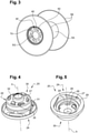
Figure 3 is a perspective view of the offigures 1 and 2 . -
Figures 4 and 5 are front and rear perspective view of an adapter bushing offigures 1 and 2 . -
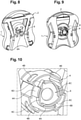
Figures 6 and 7 are side cross section views of a side flange of a spool fastened to a protrusion of an independent stand by means of one adapter bushing, at two different angular positions of the arrangement according to the invention. -
Figures 8 and 9 are front and rear perspective views of another embodiment of the independent stand of the arrangement according to the invention. -
Figure 10 is a detailed view offigure 9 . - In the description which follows, the drawing figures are not necessarily to scale and certain features may be shown in generalized or schematic form in the interest of clarity and conciseness or for informational purposes. In addition, although making and using various embodiments are discussed in detail below, it should be appreciated that as described herein are provided many inventive concepts that may embodied in a wide variety of contexts. Embodiments discussed herein are merely representative and do not limit the scope of the invention. It will also be obvious to one skilled in the art that all the technical features that are defined relative to a process can be transposed, individually or in combination, to a device and conversely, all the technical features relative to a device can be transposed, individually or in combination, to a process.
- The terms "comprise" (and any grammatical variation thereof, such as "comprises" and "comprising"), "have" (and any grammatical variation thereof, such as "has" and "having"), "contain" (and any grammatical variation thereof, such as "contains" and "containing"), and "include" (and any grammatical variation thereof such as "includes" and "including") are open-ended linking verbs. They are used to specify the presence of stated features, integers, steps or components or groups thereof, but do not preclude the presence or addition of one or more other features, integers, steps or components or groups thereof. As a result, a method, or a step in a method, that "comprises", "has", "contains", or "includes" one or more steps or elements possesses those one or more steps or elements but is not limited to possessing only those one or more steps or elements.
- As shown on
figures 1 and 2 , an arrangement is provided for unwinding cable wound onto aspool 5. Thisspool 5 comprises adrum 5A and twoside flanges 5B. Thedrum 5A is preferably cylindrical and the side flanges are preferably circular, as shown onfigure 3 . A cable (not shown) can be wound around thedrum 5A. Thespool 5 is preferably a metallic spool. Most preferably, thespool 5 is configured to withstand constraints experienced at very low temperature, e.g. below -40°C. - The arrangement comprises two
independent stands 1 intended to be removably fastened to one of the twoside flanges 5B of thespool 5. Particularly, eachindependent stand 1 is configured to be removably fastened to an outer surface of aside flanges 5B. - Each
independent stand 1 comprises aprotrusion 4 for fastening theindependent stand 1 to aside flange 5B of thespool 5. Theprotrusion 4 is formed on an inner surface of theindependent stand 1 intended to face theside flange 5B when fastened thereto. - Each
independent stand 1, preferably made from plastic, for example polypropylene or ABS, has a frontal surface lower than the circular frontal surface of eachside flange 5B and bears asupport element 2. Saidsupport element 2 is articulated from the idle position, where it is integrated into the corresponding independent stand, to an active position, where it rests on a plane supporting the spool and lifts the latter. The independent stands 1 are schematically shown onfigures 1 and 2 . A detailed embodiment of the independent stands 1 is shown and described in reference tofigures 8 to 10 . - The
support element 2 is articulated on theindependent stand 1, rotating around an axis parallel to the plane of this independent stand, by one of its ends. Thesupport element 2 is preferably integrated into the correspondingindependent stand 1 by complete frontal fitting with clipping in a corresponding slot borne by theindependent stand 1. In its extended active position, it is pivoted around the axis of its articulation and partially fitted with clipping in another slot borne by theindependent stand 1. - On its other face, the
independent stand 1 bears saidprotrusion 4, able to be removably fastened to aside flange 5B, while allowing its rotation. - The arrangement further comprises two
adapter bushings 20 to be disposed between aside flange 5B of thespool 5 and one of the independent stands 1. Eachadapter bushing 20 is configured to be removably connected to anindependent stand 1 on one side and to aside flange 5B on the opposite side. Theadapter bushing 20 is therefore sandwiched between anindependent stand 1 and aside flange 5B when saidindependent stand 1 is fastened to saidside flange 5B. - As shown on
figure 3 , eachside flange 5B ofspool 5 comprises a plurality of retainingorifices 5F configured to receive theadapter bushing 20 for a retaining arrangement. Each retaining orifice is preferably a cut-out hole formed through said side flange 5B. Said plurality of retainingorifices 5F preferably extends in circular form around acentral portion 5G of theside flange 5B. Each retainingorifice 5F may be rectangular. Each retainingorifice 5F may extend radially around thecentral portion 5G. - The retaining
orifices 5F are preferably configured to accept a twist lock arrangement. To do so, the retaining orifices comprise aninsertion portion 40 and a lockingportion 42. The section of theinsertion portion 40 is larger than the lockingportion 42. Particularly, the section of theinsertion portion 40 is larger than the section of the retaining element to allow the retaining element to be freely inserted with the retainingorifice 5F. The section of the lockingportion 42 is configured to retain the retaining element along a rotational axis A of theadapter bushing 20. - Each
side flange 5B ofspool 5 also comprises a plurality of lockingorifices 5J. Each lockingorifice 5J is configured to receive a lockingnib 35 provided onto theadapter bushing 20. The cooperation between the lockingnib 35 and thelocking orifice 5J allows to prevent rotation between saidadapter bushing 20 and saidside flange 5B when at least one lockingnib 35 is inserted in alocking orifice 5J. Each lockingorifice 5J is preferably a cut-out hole formed through saidside flange 5B. Each lockingorifice 5J is preferably complementary shaped with the lockingnib 35. Each lockingorifice 5J has preferably a circular cross-section. The plurality of lockingorifices 5J is preferably distributed around acentral portion 5G of theside flange 5B. Alternatively, eachside flange 5B ofspool 5 may comprise asingle locking orifice 5J. In this case, the adapter bushing comprises asingle locking nib 35. - As shown on
figures 4 and 5 , theadapter bushing 20 comprises abody 22 with a first connectingend 24 configured to be removably fastened to saidprotrusion 4. Thebody 22 forms at the first connectingend 24 anaperture 26 to receive saidprotrusion 4. Theprotrusion 4 is received within theaperture 26 when theadapter bushing 20 is connected to one of said independent stands 1. - The
aperture 26 forms acavity 27 with a front shape substantially circumscribed to the section of theprotrusion 4. - The
protrusion 4 comprises radial clamps 4B extending outwardly from a substantially circular main body of theprotrusion 4, as shown onfigures 9 and 10 . These radial clamps 4B are able to move in at least oneslot 29 borne by theadapter bushing 20 and oriented perpendicular to the rotational axis A of theadapter bushing 20, in order to allow the rotation of theadapter bushing 20 together with theside flange 5B. When theprotrusion 4 is inserted within thecavity 27, the radial clamps 4B are disposed in a free space between theaperture 26 and the bottom of thecavity 27. - The front shape of the
cavity 27 is substantially circumscribed to the section of the main body and the radial clamps 4B. More specifically, saidcavity 27 has a square front shape with rounded corners and bears theslot 29 on its rectilinear sides. - The
protrusion 4 is introduced into theaperture 26 of theadapter bushing 20 and it fits, with its fourradial clamps 4B, in thecavity 27 having a square front shape with rounded corners. Once it has been positioned in this way, theadapter bushing 20 can rotate freely, the radial clamps 4B being able to enter and move in theslot 29 on the rectilinear sides of thecavity 27. - A
retention surface 28 is formed by the body at the first connectingend 24. Thisretention surface 28 is configured to retain saidprotrusion 4 when theadapter bushing 20 is connected to one of said independent stands 1. Theretention surface 28 is formed by arim 29 extending inwardly from amain tube 31 of thebody 22. More specifically, saidretention surface 28 is configured to retain a retaining element of theprotrusion 4 to secure theadapter bushing 20 to theprotrusion 4. This retaining element is for example aclipping element 4A as described below with regard tofigures 8 to 10 . - The
body 22 of theadapter bushing 20 further comprises a second connectingend 30 configured to be removably fastened to said retainingorifices 5F of theside flanges 5B of thespool 5.Said body 22 comprises at the second connectingend 30 at least one retainingtab 32 configured to be clipped on saidside flange 5B. To provide the retaining arrangement, the retainingtabs 32 have a proximal end fixed to themain tube 31 of thebody 22 and a free distal end at the opposite. Particularly, themain tube 31 comprises afront surface 37 extending perpendicularly to the rotational axis of theadapter bushing 20. The retainingtabs 32 are fixed to thisfront surface 37. Thisfront surface 37 forms a bottom surface of thebody 22 so that theadapter bushing 20 has an elongated hollow section with a closed end. - Each retaining
tab 32 is able to be elastically deformed in a radial direction to be first inserted within the retainingorifices 5F. Then, aretention surface 33 of the retainingtabs 32 contacts an inner wall of theside flange 5B near the retainingorifice 5F to retain the retainingtab 32. This retaining arrangement is configured to be removable when needed. - The
body 22 preferably comprises a plurality of retainingtabs 32 distributed on themain tube 31 around the rotational axis of theadapter bushing 20. Each retainingtab 32 is configured to be clipped on aretaining orifice 5F of aside flange 5B. - Said
adapter bushing 20 further comprises at the second connectingend 30 at least one lockingnib 35 configured to be inserted in at least onelocking orifice 5J. The cooperation between a lockingnib 35 and alocking orifice 5J allows to prevent rotation between saidadapter bushing 20 and saidside flange 5B when the lockingnib 35 is inserted in saidlocking orifice 5J. The lockingnib 35 is preferably a spring-loaded nib which acts as detent to prevent unlocking of theadapter bushing 20. - Connection between the
adapter bushing 20 and theside flange 5B is therefore divided in two functions; a retaining function along the rotational axis of theadapter bushing 20 obtained by the cooperation between the retainingtabs 32 and the retainingorifices 5F and a rotational locking function obtained by the cooperation between the lockingnibs 35 and thelocking orifices 5J. - The cooperation between the locking
nib 35 and thelocking orifices 5J allows to drive thespool 5 during winding. - The
body 22 further comprises a bearingouter surface 34 distinct from said retainingtabs 32. In other words, the bearingouter surface 34 is formed at a greater diameter than the retainingtabs 32. Said bearingouter surface 34 is configured to provide a close fit cooperation with aninner bearing surface 5H formed on eachside flange 5B. The bearingouter surface 34 is circular outer surface of thebody 22. The bearinginner surface 5H is a circular inner surface of aside flange 5B. This close fit cooperation allows radial load from thespool 5 to be exerted on the bearingouter surface 34 rather than on the retainingtabs 32. -
Figures 6 and 7 show cross section views of anindependent stand 1 fastened to aside flange 5B by means of anadapter bushing 20. In this position, the retainingtabs 32 are positioned through the retainingorifices 5F of theside flange 5C. The retainingsurface 33 of the retainingtabs 32 contacts the inner wall of theside flange 5C. Furthermore, the bearingouter surface 34 of theadapter bushing 20 contacts the bearinginner surface 5H to withstand radial load. Therim 29 is lodged within aslot 4F formed in theprotrusion 4. Thisslot 4F may be formed for example by aclipping element 4A of theprotrusion 4. - In a preferred embodiment, the
protrusions 4 are configured to be either indirectly fastened to aside flange 5B of aspool 5 by means of anadapter bushing 20 or directly within a central orifice provided in the side flange of a different spool. As detailed above, thespool 5 is preferably a metallic spool and said different spool having a central orifice is a plastic spool for which the arrangement is initially designed. -
Figures 8 to 10 show an embodiment of theprotrusion 4 of the independent stands 1. - In
figures 8 and 9 , theindependent stand 1 bears its articulatedsupport element 2, in the idle position, where it is integrated into the corresponding independent stand. - In this embodiment each
protrusion 4 includes aclipping element 4A able to be clipped on the inner face of each flange, when theprotrusion flange 5B. - According to this variant, the
clipping element 4A is able to be clipped on the inner face of each flange, using akey 6 providing the expansion of the clipping arrangement on the inner face of each flange and is able to be actuated from outside the arrangement, by rotation of apawl 6A, which can be seen infigure 8 . - As can be seen in
figure 10 particularly, thiskey 6 provides the expansion of theclipping arrangement 4A on the inner face of each flange, during its rotation, owing to aradial clamp 6B bearing roundedinclined planes 6C. - The key 6 also includes an end-of-
travel stop 6D, for blocking on a catching part borne by the unwinding arrangement. - The
protrusion 4 has radial clamps 4B able to move in at least one slot borne by each flange and oriented parallel to the plane of each flange, in order to allow the rotation of each flange.
Claims (12)
- An arrangement for unwinding a cable wound onto a spool (5) made up of a central drum (5A) and two side flanges (5B), the arrangement comprising:- at least one independent stand (1) comprising a protrusion (4) for fastening the independent stand (1) to at least one retaining orifice (5F) of a side flange of the spool (5),- at least one adapter bushing to be disposed between said protrusion (4) of said independent stand (1) and said at least one retaining orifice (5F) of one of the side flanges of the spool (5), said at least one adapter bushing being configured to removably fasten said independent stand (1) to said one of the side flanges of the spool (5).
- The arrangement according to claim 1, wherein the adapter bushing comprises a body with a first connecting end configured to be removably fastened to said protrusion and a second connecting end configured to be removably fastened to said at least one retaining orifice (5F) of the side flanges.
- The arrangement according to claim 2, wherein said body forms at the first connecting end an aperture to receive said protrusion, when the adapter bushing is connected to said independent stand, said body further forming at the first connecting end a retention surface configured to retain said protrusion when the adapter bushing is connected to said independent stand.
- The arrangement according to claim 3, wherein said protrusion (4) comprises a clipping element (4A) configured to be clipped on said first connecting end of said adapter bushing, when said protrusion (4) is fitted in the aperture of said adapter bushing.
- The arrangement according to claim 4, wherein said clipping element (4A) is configured to be clipped on said first connecting end, using a key providing the expansion of said clipping element on said first connecting end and configured to be actuated from outside said arrangement.
- The arrangement according to any one of claims 2 to 5, wherein said body of said adapter bushing comprises at the second connecting end at least one retaining tab configured to be clipped on said side flange at said at least one retaining orifice.
- The arrangement according to claim 6, wherein said adapter bushing further comprises a bearing outer surface distinct from said at least one retaining tab, said bearing outer surface being configured to provide a close fit cooperation with an inner bearing surface formed on said side flange so as to bear radial load from the spool.
- The arrangement according to any one of claims 2 to 7, wherein said body of said adapter bushing comprises at the second connecting end at least one locking nib configured to be inserted in at least one locking orifice of said side flange to prevent rotation between said adapter bushing and said side flange when the at least one locking nib is inserted in said at least one locking orifice.
- The arrangement according to any one of the preceding claims, wherein said independent stand (1) bears a support element (2) articulated from an idle position, where said support element (2) is integrated in a corresponding slot (3A) formed by said independent stand (1), to an active position, where the support element (2) is configured to support and lift the spool (5) when resting on a plane.
- A cable unwinding set comprising the arrangement according to any one of the preceding claims and a spool (5) having a central drum (5A) and two side flanges (5B), said arrangement comprising two independent stands and two adapter bushings for removably fastening each of the independent stands (1) to a side flange of the spool (5).
- The cable unwinding set according to claim 10, wherein each side flange comprises a plurality of retaining orifices configured to receive an adapter bushing for a clipping arrangement, said plurality of retaining orifices extending in circular form around a central portion of the side flange.
- An adapter bushing to be disposed between a protrusion (4) of an independent stand (1) and a side flange of a spool (5), said adapter bushing being configured to removably fasten said independent stand (1) to said side flange of the spool (5).
Applications Claiming Priority (1)
| Application Number | Priority Date | Filing Date | Title |
|---|---|---|---|
| CA3092395A CA3092395A1 (en) | 2020-09-08 | 2020-09-08 | Arrangement for unwinding cable wound onto a spool |
Publications (1)
| Publication Number | Publication Date |
|---|---|
| EP3964466A1 true EP3964466A1 (en) | 2022-03-09 |
Family
ID=77989754
Family Applications (1)
| Application Number | Title | Priority Date | Filing Date |
|---|---|---|---|
| EP21306223.5A Withdrawn EP3964466A1 (en) | 2020-09-08 | 2021-09-08 | Arrangement for unwinding cable wound onto a spool |
Country Status (3)
| Country | Link |
|---|---|
| US (1) | US20220081248A1 (en) |
| EP (1) | EP3964466A1 (en) |
| CA (1) | CA3092395A1 (en) |
Cited By (1)
| Publication number | Priority date | Publication date | Assignee | Title |
|---|---|---|---|---|
| FR3134572A1 (en) | 2022-04-19 | 2023-10-20 | Nexans | LOCKABLE AND REMOVABLE SUPPORT FOR REEL |
Families Citing this family (2)
| Publication number | Priority date | Publication date | Assignee | Title |
|---|---|---|---|---|
| IT201800004294A1 (en) * | 2018-04-06 | 2019-10-06 | DEVICE FOR THE HANDLING OF REELS | |
| CA3206937A1 (en) * | 2021-02-05 | 2022-08-11 | Brian HONSINGER | Reusable reel holder and bag with reusable reel holder |
Citations (4)
| Publication number | Priority date | Publication date | Assignee | Title |
|---|---|---|---|---|
| US4948064A (en) * | 1988-12-19 | 1990-08-14 | Neil Richard | Universal spool support system |
| EP0449076A1 (en) | 1990-03-30 | 1991-10-02 | Nokia-Maillefer Holding S.A. | An arrangement in an automatic cable winding machine |
| US6234421B1 (en) * | 1996-10-24 | 2001-05-22 | Vandor Corporation | Reel having secured flanges |
| EP3333107B1 (en) | 2016-12-06 | 2019-07-24 | Nexans | Arrangement for unwinding cable wound onto a reel |
-
2020
- 2020-09-08 CA CA3092395A patent/CA3092395A1/en active Pending
-
2021
- 2021-09-03 US US17/467,007 patent/US20220081248A1/en not_active Abandoned
- 2021-09-08 EP EP21306223.5A patent/EP3964466A1/en not_active Withdrawn
Patent Citations (4)
| Publication number | Priority date | Publication date | Assignee | Title |
|---|---|---|---|---|
| US4948064A (en) * | 1988-12-19 | 1990-08-14 | Neil Richard | Universal spool support system |
| EP0449076A1 (en) | 1990-03-30 | 1991-10-02 | Nokia-Maillefer Holding S.A. | An arrangement in an automatic cable winding machine |
| US6234421B1 (en) * | 1996-10-24 | 2001-05-22 | Vandor Corporation | Reel having secured flanges |
| EP3333107B1 (en) | 2016-12-06 | 2019-07-24 | Nexans | Arrangement for unwinding cable wound onto a reel |
Cited By (2)
| Publication number | Priority date | Publication date | Assignee | Title |
|---|---|---|---|---|
| FR3134572A1 (en) | 2022-04-19 | 2023-10-20 | Nexans | LOCKABLE AND REMOVABLE SUPPORT FOR REEL |
| EP4265551A1 (en) | 2022-04-19 | 2023-10-25 | Nexans | Lockable and removable support for a reel |
Also Published As
| Publication number | Publication date |
|---|---|
| US20220081248A1 (en) | 2022-03-17 |
| CA3092395A1 (en) | 2022-03-08 |
Similar Documents
| Publication | Publication Date | Title |
|---|---|---|
| US20220081248A1 (en) | Arrangement for unwinding cable wound onto a spool | |
| US4967976A (en) | Take-up spindle | |
| US8191836B2 (en) | Snap-in cable hanger clip | |
| US7876992B2 (en) | Drumless cable reel | |
| US6199918B1 (en) | Plug-in rapid-action coupling device | |
| US12298582B2 (en) | Cable management device | |
| EP0992446A2 (en) | A payout tube and a container for a wound coil with such a payout tube | |
| HUP0302854A2 (en) | Cable storage spool | |
| US4610555A (en) | Universal ribbon spool for typewriters and other machines | |
| CA2149927A1 (en) | One-piece reelex payout tube | |
| WO2019212887A1 (en) | Tray tower with position indexing trays | |
| US6089500A (en) | Collapsible winding spool having a bayonet coupling between the hub and the flange | |
| US20250033925A1 (en) | Devices for cable management | |
| ES2869165T3 (en) | Retainer assembly for flexible support members of an optical cable | |
| WO2005108266A1 (en) | Apparatus for centering media on a spindle | |
| US20080061187A1 (en) | Reel assembly | |
| DE2756023B2 (en) | Cable winder with a cable drum | |
| EP0390020B1 (en) | Pressure spring for cassettes and related cassettes | |
| WO2016028647A1 (en) | Fiber storage device | |
| DE4309350C2 (en) | Installation device with glass or plastic fiber plugs | |
| US20240400344A1 (en) | Snap-together reel with reinforced tab | |
| KR100657187B1 (en) | Optical cable | |
| US6259852B1 (en) | Fiber optic pedestal | |
| JP2001268757A (en) | Band clamp for corrugated tube | |
| AU2020289736B2 (en) | Coiled product dispensing kit |
Legal Events
| Date | Code | Title | Description |
|---|---|---|---|
| PUAI | Public reference made under article 153(3) epc to a published international application that has entered the european phase |
Free format text: ORIGINAL CODE: 0009012 |
|
| STAA | Information on the status of an ep patent application or granted ep patent |
Free format text: STATUS: THE APPLICATION HAS BEEN PUBLISHED |
|
| AK | Designated contracting states |
Kind code of ref document: A1 Designated state(s): AL AT BE BG CH CY CZ DE DK EE ES FI FR GB GR HR HU IE IS IT LI LT LU LV MC MK MT NL NO PL PT RO RS SE SI SK SM TR |
|
| STAA | Information on the status of an ep patent application or granted ep patent |
Free format text: STATUS: REQUEST FOR EXAMINATION WAS MADE |
|
| 17P | Request for examination filed |
Effective date: 20220909 |
|
| RBV | Designated contracting states (corrected) |
Designated state(s): AL AT BE BG CH CY CZ DE DK EE ES FI FR GB GR HR HU IE IS IT LI LT LU LV MC MK MT NL NO PL PT RO RS SE SI SK SM TR |
|
| STAA | Information on the status of an ep patent application or granted ep patent |
Free format text: STATUS: EXAMINATION IS IN PROGRESS |
|
| 17Q | First examination report despatched |
Effective date: 20231220 |
|
| STAA | Information on the status of an ep patent application or granted ep patent |
Free format text: STATUS: THE APPLICATION IS DEEMED TO BE WITHDRAWN |
|
| 18D | Application deemed to be withdrawn |
Effective date: 20240423 |