EP3964450A1 - Blister packaging container having shoulder part-integrated fliptop cap - Google Patents
Blister packaging container having shoulder part-integrated fliptop cap Download PDFInfo
- Publication number
- EP3964450A1 EP3964450A1 EP20798404.8A EP20798404A EP3964450A1 EP 3964450 A1 EP3964450 A1 EP 3964450A1 EP 20798404 A EP20798404 A EP 20798404A EP 3964450 A1 EP3964450 A1 EP 3964450A1
- Authority
- EP
- European Patent Office
- Prior art keywords
- cap
- connection portion
- discharge hole
- fliptop
- blister packaging
- Prior art date
- Legal status (The legal status is an assumption and is not a legal conclusion. Google has not performed a legal analysis and makes no representation as to the accuracy of the status listed.)
- Granted
Links
Images


Classifications
-
- B—PERFORMING OPERATIONS; TRANSPORTING
- B65—CONVEYING; PACKING; STORING; HANDLING THIN OR FILAMENTARY MATERIAL
- B65D—CONTAINERS FOR STORAGE OR TRANSPORT OF ARTICLES OR MATERIALS, e.g. BAGS, BARRELS, BOTTLES, BOXES, CANS, CARTONS, CRATES, DRUMS, JARS, TANKS, HOPPERS, FORWARDING CONTAINERS; ACCESSORIES, CLOSURES, OR FITTINGS THEREFOR; PACKAGING ELEMENTS; PACKAGES
- B65D47/00—Closures with filling and discharging, or with discharging, devices
- B65D47/04—Closures with discharging devices other than pumps
- B65D47/06—Closures with discharging devices other than pumps with pouring spouts or tubes; with discharge nozzles or passages
- B65D47/08—Closures with discharging devices other than pumps with pouring spouts or tubes; with discharge nozzles or passages having articulated or hinged closures
-
- B—PERFORMING OPERATIONS; TRANSPORTING
- B65—CONVEYING; PACKING; STORING; HANDLING THIN OR FILAMENTARY MATERIAL
- B65D—CONTAINERS FOR STORAGE OR TRANSPORT OF ARTICLES OR MATERIALS, e.g. BAGS, BARRELS, BOTTLES, BOXES, CANS, CARTONS, CRATES, DRUMS, JARS, TANKS, HOPPERS, FORWARDING CONTAINERS; ACCESSORIES, CLOSURES, OR FITTINGS THEREFOR; PACKAGING ELEMENTS; PACKAGES
- B65D47/00—Closures with filling and discharging, or with discharging, devices
- B65D47/04—Closures with discharging devices other than pumps
- B65D47/06—Closures with discharging devices other than pumps with pouring spouts or tubes; with discharge nozzles or passages
- B65D47/08—Closures with discharging devices other than pumps with pouring spouts or tubes; with discharge nozzles or passages having articulated or hinged closures
- B65D47/0804—Closures with discharging devices other than pumps with pouring spouts or tubes; with discharge nozzles or passages having articulated or hinged closures integrally formed with the base element provided with the spout or discharge passage
- B65D47/0833—Hinges without elastic bias
- B65D47/0838—Hinges without elastic bias located at an edge of the base element
-
- B—PERFORMING OPERATIONS; TRANSPORTING
- B65—CONVEYING; PACKING; STORING; HANDLING THIN OR FILAMENTARY MATERIAL
- B65D—CONTAINERS FOR STORAGE OR TRANSPORT OF ARTICLES OR MATERIALS, e.g. BAGS, BARRELS, BOTTLES, BOXES, CANS, CARTONS, CRATES, DRUMS, JARS, TANKS, HOPPERS, FORWARDING CONTAINERS; ACCESSORIES, CLOSURES, OR FITTINGS THEREFOR; PACKAGING ELEMENTS; PACKAGES
- B65D75/00—Packages comprising articles or materials partially or wholly enclosed in strips, sheets, blanks, tubes or webs of flexible sheet material, e.g. in folded wrappers
- B65D75/28—Articles or materials wholly enclosed in composite wrappers, i.e. wrappers formed by associating or interconnecting two or more sheets or blanks
- B65D75/30—Articles or materials enclosed between two opposed sheets or blanks having their margins united, e.g. by pressure-sensitive adhesive, crimping, heat-sealing, or welding
- B65D75/32—Articles or materials enclosed between two opposed sheets or blanks having their margins united, e.g. by pressure-sensitive adhesive, crimping, heat-sealing, or welding one or both sheets or blanks being recessed to accommodate contents
- B65D75/36—Articles or materials enclosed between two opposed sheets or blanks having their margins united, e.g. by pressure-sensitive adhesive, crimping, heat-sealing, or welding one or both sheets or blanks being recessed to accommodate contents one sheet or blank being recessed and the other formed of relatively stiff flat sheet material, e.g. blister packages, the recess or recesses being preformed
- B65D75/366—Articles or materials enclosed between two opposed sheets or blanks having their margins united, e.g. by pressure-sensitive adhesive, crimping, heat-sealing, or welding one or both sheets or blanks being recessed to accommodate contents one sheet or blank being recessed and the other formed of relatively stiff flat sheet material, e.g. blister packages, the recess or recesses being preformed and forming one compartment
-
- B—PERFORMING OPERATIONS; TRANSPORTING
- B65—CONVEYING; PACKING; STORING; HANDLING THIN OR FILAMENTARY MATERIAL
- B65D—CONTAINERS FOR STORAGE OR TRANSPORT OF ARTICLES OR MATERIALS, e.g. BAGS, BARRELS, BOTTLES, BOXES, CANS, CARTONS, CRATES, DRUMS, JARS, TANKS, HOPPERS, FORWARDING CONTAINERS; ACCESSORIES, CLOSURES, OR FITTINGS THEREFOR; PACKAGING ELEMENTS; PACKAGES
- B65D75/00—Packages comprising articles or materials partially or wholly enclosed in strips, sheets, blanks, tubes or webs of flexible sheet material, e.g. in folded wrappers
- B65D75/52—Details
- B65D75/58—Opening or contents-removing devices added or incorporated during package manufacture
- B65D75/5805—Opening or contents-removing devices added or incorporated during package manufacture for tearing a side strip parallel and next to the edge, e.g. by means of a line of weakness
-
- B—PERFORMING OPERATIONS; TRANSPORTING
- B65—CONVEYING; PACKING; STORING; HANDLING THIN OR FILAMENTARY MATERIAL
- B65D—CONTAINERS FOR STORAGE OR TRANSPORT OF ARTICLES OR MATERIALS, e.g. BAGS, BARRELS, BOTTLES, BOXES, CANS, CARTONS, CRATES, DRUMS, JARS, TANKS, HOPPERS, FORWARDING CONTAINERS; ACCESSORIES, CLOSURES, OR FITTINGS THEREFOR; PACKAGING ELEMENTS; PACKAGES
- B65D75/00—Packages comprising articles or materials partially or wholly enclosed in strips, sheets, blanks, tubes or webs of flexible sheet material, e.g. in folded wrappers
- B65D75/52—Details
- B65D75/58—Opening or contents-removing devices added or incorporated during package manufacture
- B65D75/5827—Tear-lines provided in a wall portion
-
- B—PERFORMING OPERATIONS; TRANSPORTING
- B65—CONVEYING; PACKING; STORING; HANDLING THIN OR FILAMENTARY MATERIAL
- B65D—CONTAINERS FOR STORAGE OR TRANSPORT OF ARTICLES OR MATERIALS, e.g. BAGS, BARRELS, BOTTLES, BOXES, CANS, CARTONS, CRATES, DRUMS, JARS, TANKS, HOPPERS, FORWARDING CONTAINERS; ACCESSORIES, CLOSURES, OR FITTINGS THEREFOR; PACKAGING ELEMENTS; PACKAGES
- B65D75/00—Packages comprising articles or materials partially or wholly enclosed in strips, sheets, blanks, tubes or webs of flexible sheet material, e.g. in folded wrappers
- B65D75/52—Details
- B65D75/58—Opening or contents-removing devices added or incorporated during package manufacture
- B65D75/5861—Spouts
- B65D75/5872—Non-integral spouts
- B65D75/5883—Non-integral spouts connected to the package at the sealed junction of two package walls
-
- Y—GENERAL TAGGING OF NEW TECHNOLOGICAL DEVELOPMENTS; GENERAL TAGGING OF CROSS-SECTIONAL TECHNOLOGIES SPANNING OVER SEVERAL SECTIONS OF THE IPC; TECHNICAL SUBJECTS COVERED BY FORMER USPC CROSS-REFERENCE ART COLLECTIONS [XRACs] AND DIGESTS
- Y02—TECHNOLOGIES OR APPLICATIONS FOR MITIGATION OR ADAPTATION AGAINST CLIMATE CHANGE
- Y02W—CLIMATE CHANGE MITIGATION TECHNOLOGIES RELATED TO WASTEWATER TREATMENT OR WASTE MANAGEMENT
- Y02W30/00—Technologies for solid waste management
- Y02W30/50—Reuse, recycling or recovery technologies
- Y02W30/80—Packaging reuse or recycling, e.g. of multilayer packaging
Definitions
- the present invention relates to a blister packaging container that is configured to allow a container part of a given space to be provided by thermoforming a plastic film or sheet, to fill medicine or other products in the container part of the given space, and to attach a cover sheet to the inlet of the container part to seal the container part.
- a blister packaging container is made by heating and plasticizing a thermoplastic sheet, placing the thermoplastic sheet on a mold, molding the thermoplastic sheet to a container part by means of compression or vacuum molding, filling contents into the container part, and bonding a cover formed of a sheet of paper or plastic laminate film only to the flat flange portion of the container part by means of heat sealing, high frequency bonding, ultrasonic bonding, or the like, and the blister packaging container is widely used for packaging food, daily supplies, miscellaneous goods, industrial products, tablet medicine, liquid cosmetics, and the like.
- the blister packaging container includes a container part for accommodating contents therein, a discharge hole formed on one end of the container part, and a cover film for sealing the discharge hole, and to use the contents accommodated in the container part, generally, the discharge hole is bent to open or the cover film is removed from the discharge hole. After the discharge hole has been open once, however, it is impossible to close the discharge hole again.
- a conventional blister packaging container including a container part protruding to a given shape and having a short pipelike discharge hole formed on top end thereof and a cover sheet attached to the flange of the container part and having a bonding part attached to the flange to perform a bonding function, a non-bonding part easily taken by a user when separated and removed from the container part, and a non-bonding discharging part with a given area adapted to communicate with the discharge hole of the container part
- the container part includes: a folding inducing groove concavely formed transversely with respect to the flange close to the top end of the discharge hole to perform bending line setting and resistance reduction when a folding sealing piece as will be discussed later is folded; the folding sealing piece disposed above the folding inducing groove; one pair of locking pieces protruding from both ends of the folding sealing piece and having locking protrusions from the top ends of the inner sides thereof; one pair of locking side portions disposed under both ends of the folding inducing
- the folding sealing piece connected to the discharge hole is folded to compress the opening space of the discharge hole, and the folding sealing piece is thus supportedly fixed to the discharge hole as the pair of locking pieces disposed on both ends thereof is locked onto the edge of the discharge hole.
- the pair of locking pieces escapes from the edge of the discharge hole to cause the compression of the folding sealing piece against the discharge hole to be released, so that an empty space between the folding sealing piece and the discharge hole may occur, thereby undesirably permitting the leakage of the contents in the container part.
- the present invention has been made in view of the above-mentioned problems occurring in the related art, and it is an object of the present invention to provide a blister packaging container having a shoulder part-integrated fliptop cap that is capable of opening and closing a container part multiple times and preventing an empty space from occurring when the container part is closed again, thereby improving sealing ability thereof.
- a blister packaging container having a shoulder part-integrated fliptop cap, including: a container part for accommodating contents therein; a shoulder part fixedly inserted into the inlet of the container part; and a fliptop cap comprising a cap body connected integrally with the shoulder part and having a discharge hole adapted to discharge the contents therefrom and a cap cover foldably connected to the cap body through a cap hinge and having an opening and closing protrusion inserted into the discharge hole to seal the discharge hole.
- the fliptop cap may include a locking portion protruding from the inner peripheral surface of the discharge hole to compressingly fix the opening and closing protrusion thereto.
- the fliptop cap may include a guide portion formed on one end of the discharge hole into which the opening and closing protrusion is inserted in such a manner as to be enlarged in diameter toward the discharging direction of the contents, and the opening and closing protrusion is enlargedly formed in diameter toward the discharging direction of the contents in the state of being inserted into the discharge hole.
- the opening and closing protrusion may have a maximum diameter portion smaller than a maximum diameter portion of the guide portion and larger than a minimum diameter portion of the guide portion.
- the cap body may include a stepped portion formed steppedly on the edge periphery of one surface where the discharge hole is formed
- the cap cover may include a concave portion concavely formed at the inner surface thereof, so that the stepped portion of the cap body is fittedly inserted into the concave portion of the cap cover.
- the blister packaging container may further include a packaging part extended from the inlet of the container part to sealingly accommodate the fliptop cap therein; and a cut-off line formed on a connection portion between the container part and the packaging part.
- the packaging part may include an accommodation portion in which the cap hinge is accommodated, and the accommodation portion protrudes outwardly from a given portion of the packaging part.
- the cap hinge may include a first connection portion connected to the cap body, a second connection portion connected to the cap cover, and a folding portion connecting the first connection portion and the second connection portion, the first connection portion and the second connection portion being folded to each other around the folding portion and being tapered toward the folding portion, so that in a state where the inner surface of the first connection portion comes into contact with the inner surface of the second connection portion, the inner surface of the first connection portion is parallel to the inner surface of the second connection portion, and the outer surface of the first connection portion is formed as a first inclined surface that is slant from the inner surface of the first connection portion, while the outer surface of the second connection portion is being formed as a second inclined surface that is slant from the inner surface of the second connection portion.
- the blister packaging container is capable of opening and closing the container part multiple times through the opening and closing protrusion of the cap cover for opening and closing the discharge hole of the cap body and preventing an empty space from occurring when the container part is closed again, thereby improving sealing ability thereof.
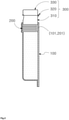
- FIG. 1 is a side view showing a blister packaging container having a shoulder part-integrated fliptop cap according to the present invention
- FIG. 2 is a plan perspective view showing a fliptop cap of the blister packaging container according to the present invention
- FIG. 3 is a bottom perspective view showing the fliptop cap of the blister packaging container according to the present invention
- FIG. 4 is a front view showing a state where the fliptop cap is open
- FIG. 5 is a sectional view showing a state where the fliptop cap is open
- FIG. 6 is a sectional view showing a state where the fliptop cap is closed.
- the blister packaging container having a shoulder part-integrated fliptop cap includes a container part 100, a shoulder part 200, and a fliptop cap 300.
- the container part 100 is manufactured by heating a sheet, inserting the sheet into a mold, molding an accommodation space, filling contents into the accommodation space of the sheet, attaching a film to the sheet, and cutting the sheet to a predetermined shape.
- the sheet is made of a plastic laminate material, and the film is attached to the sheet by means of high frequency or ultrasonic rolls.
- the shoulder part 200 is fixedly inserted into the inlet of the container part 100, is hollow at the inside thereof, and passes the contents stored in the container part 100 therethrough.
- the shoulder part 200 has a shoulder concave and convex portion 201 formed along the outer peripheral surface thereof to improve sealing with the inner peripheral surface of the container part 100.
- the container part 100 has a container concave and convex portion 101 formed along the inner peripheral surface coming into contact with the outer peripheral surface of the shoulder part 200 to improve sealing with the outer peripheral surface of the shoulder part 200.
- the fliptop cap 300 serves to adjust an amount of contents discharged and includes a cap body 310 and a cap cover 330.
- the cap body 310 is a basic body of the fliptop cap 300 connected integrally with the shoulder part 200 and has a discharge hole 311 for discharging the contents therefrom.
- the discharge hole 311 is conically shaped to decrease the discharging speed of the contents.
- the cap cover 330 functions to open and close the discharge hole 311, is foldably connected to the cap body 310 through a cap hinge 320, and has an opening and closing protrusion 331 inserted into the discharge hole 311 to seal the discharge hole 311.
- the blister packaging container having a shoulder part-integrated fliptop cap is configured to allow the container part 100 to be open and closed multiple times by means of the opening and closing protrusion 331 of the cap cover 330 that opens and closes the discharge hole 311 of the cap body 310 and to prevent an empty space from being formed when the container part 100 is closed again to thus improve the sealing ability thereof.
- the discharge hole 311 of the fliptop cap 300 includes a locking portion 311a protruding from the inner peripheral surface thereof to compressingly fix the opening and closing protrusion 331 thereto.
- the locking portion 311a is a stepped portion with a minimum diameter at the inside of the discharge hole 311.
- the locking portion 311a compressingly fixes the opening and closing protrusion 331 thereto, and as the locking portion 311a compresses the opening and closing protrusion 331 inwardly, in this case, the opening and closing protrusion 331 becomes open outwardly to thus come into close contact with the locking portion 311a, thereby improving the sealing with the locking portion 311a.
- the opening and closing protrusion 331 is made of an elastic material.
- the discharge hole 311 of the fliptop cap 300 includes a guide portion 311b formed on one end into which the opening and closing protrusion 331 is inserted in such a manner as to be enlarged in diameter toward the discharging direction of the contents, and the opening and closing protrusion 331 is enlargedly formed in diameter toward the discharging direction of the contents in the state of being inserted into the discharge hole 311.
- the guide portion 311b is conically shaped, and further, the opening and closing protrusion 331 is conically shaped.
- the guide portion 311b serves to guide the opening and closing protrusion 331 inserted into the discharge hole 311 to the inside of the discharge hole 311.
- the opening and closing protrusion 331 has a maximum diameter portion 331a smaller than the maximum diameter portion of the guide portion 311b and larger than a minimum diameter portion of the guide portion 311b.
- the diameter of the maximum diameter portion 331a of the opening and closing protrusion 331 is set between the maximum diameter portion and the minimum diameter portion of the guide portion 311b, and if the opening and closing protrusion 331 is inserted into the guide portion 311b of the discharge hole 311, accordingly, the maximum diameter portion 331a of the opening and closing protrusion 331 does not pass through the guide portion 311b, so that the maximum diameter portion 331a of the opening and closing protrusion 331 or a specific portion with a diameter smaller than the maximum diameter portion 331a is seated onto the guide portion 311b.
- the cap body 310 includes a stepped portion 312 formed steppedly on the edge periphery of one surface where the discharge hole 311 is formed, and the cap cover 330 has a concave portion 332 concavely formed at the inner surface thereof, so that the stepped portion 312 of the cap body 310 is fittedly inserted into the concave portion 332 of the cap cover 330.
- the concave portion 332 is formed concavely on the inner surface of the cap cover 330 facing the cap body 310 in the state where the opening and closing protrusion 331 of the cap cover 330 is inserted into the discharge hole 311 of the cap body 310.
- the fliptop cap 300 has first sealing through the fitting coupling between the concave portion 332 of the cap cover 330 and the stepped portion 312 of the cap body 310 and second sealing through the compressing fixing between the opening and closing protrusion 331 of the cap cover 330 and the locking portion 311a of the discharge hole 311 of the cap body 310, thereby more strengthening the sealing ability thereof.
- FIG. 7 is a front view showing a state where a packaging part is provided to the blister packaging container according to the present invention
- FIG. 8 is a side view showing the state where the packaging part is provided to the blister packaging container according to the present invention
- FIG. 9 is an exploded view showing a state where the packaging part is separated from the blister packaging container according to the present invention.
- the blister packaging container having a shoulder part-integrated fliptop cap according to the present invention further includes a packaging part 400 and a cut-off line 500.
- the packaging part 400 is extended from the inlet of the container part 100 to sealingly accommodate the fliptop cap 300 therein.
- the packaging part 400 serves to package the fliptop cap 300, and when the contents of the container part 100 are first used by a user, the packaging part 400 is separated and removed from the container part 100 by cutting the cut-off line 500.
- packaging part 400 is made of the same material as the container part 100.
- the cut-off line 500 is formed on a connection portion between the container part 100 and the packaging part 400, and so as to reduce a cut-off resistance, the sectional area of the cut-off line 500 is smaller than that of the packaging part 400.
- the packaging part 400 has an accommodation portion 410 as a space in which the cap hinge 320 is accommodated, and the accommodation portion 410 protrudes outwardly from a given portion of the packaging part 400.
- the accommodation portion 410 has a curved surface with a given curvature along the given portion of the packaging part 400 and is formed with an archshaped section.
- the cap hinge 320 includes a first connection portion 321 connected to the cap body 310, a second connection portion 322 connected to the cap cover 330, and a folding portion 323 connecting the first connection portion 321 and the second connection portion 322.
- first connection portion 321 and the second connection portion 322 are folded to each other around the folding portion 323, and the folding portion 323 has the shape of a plate.
- first connection portion 321 and the second connection portion 322 are tapered toward the folding portion 323.
- the inner surface of the first connection portion 321 is parallel to the inner surface of the second connection portion 322.
- the outer surface of the first connection portion 321 is formed as a first inclined surface 321a that is slant from the inner surface of the first connection portion 321
- the outer surface of the second connection portion 322 is formed as a second inclined surface 322a that is slant from the inner surface of the second connection portion 322.
- the folding portion 323 is curved with a given curvature, and the first inclined surface 321a and the second inclined surface 322a do not protrude outwardly, so that when the cap hinge 320 is inserted into the packaging part 400, the packaging part 400 can be prevented from being damaged by the cap hinge 320.
- one surface of the cap body 310 in a horizontal direction is curved, and the other surface thereof in the horizontal direction is flat, so that the cap hinge 320 is horizontally connected to the flat surface of the cap body 310. While the cap body 310 and the cap cover 330 are being folded to each other, accordingly, a pressure applied to the cap hinge 320 located between the cap body 310 and the cap cover 330 can be uniformly distributed to the cap hinge 320.
- FIG. 10 is an exploded perspective view showing other examples of the shoulder part and the fliptop cap of the blister packaging container according to the present invention.
- a shoulder part 200 and a fliptop cap 300 are separable from each other. Further, the shoulder part 200 has a should screw thread 202, and the fliptop cap 300 has a cap screw thread 313 formed on the cap body 310 thereof, so that they can be coupled to each other by means of the screw coupling between the should screw thread 202 and the cap screw thread 313.
- the present invention may be applied to various fields related to food, cosmetics, medicine, daily supplies, and industrial products, without being limited thereto.
Landscapes
- Engineering & Computer Science (AREA)
- Mechanical Engineering (AREA)
- Chemical & Material Sciences (AREA)
- Composite Materials (AREA)
- Closures For Containers (AREA)
- Packages (AREA)
- Details Of Rigid Or Semi-Rigid Containers (AREA)
Abstract
Description
- The present invention relates to a blister packaging container that is configured to allow a container part of a given space to be provided by thermoforming a plastic film or sheet, to fill medicine or other products in the container part of the given space, and to attach a cover sheet to the inlet of the container part to seal the container part.
- Generally, a blister packaging container is made by heating and plasticizing a thermoplastic sheet, placing the thermoplastic sheet on a mold, molding the thermoplastic sheet to a container part by means of compression or vacuum molding, filling contents into the container part, and bonding a cover formed of a sheet of paper or plastic laminate film only to the flat flange portion of the container part by means of heat sealing, high frequency bonding, ultrasonic bonding, or the like, and the blister packaging container is widely used for packaging food, daily supplies, miscellaneous goods, industrial products, tablet medicine, liquid cosmetics, and the like.
- Further, the blister packaging container includes a container part for accommodating contents therein, a discharge hole formed on one end of the container part, and a cover film for sealing the discharge hole, and to use the contents accommodated in the container part, generally, the discharge hole is bent to open or the cover film is removed from the discharge hole. After the discharge hole has been open once, however, it is impossible to close the discharge hole again.
- To solve such problems, there is provided a conventional blister packaging container including a container part protruding to a given shape and having a short pipelike discharge hole formed on top end thereof and a cover sheet attached to the flange of the container part and having a bonding part attached to the flange to perform a bonding function, a non-bonding part easily taken by a user when separated and removed from the container part, and a non-bonding discharging part with a given area adapted to communicate with the discharge hole of the container part, wherein the container part includes: a folding inducing groove concavely formed transversely with respect to the flange close to the top end of the discharge hole to perform bending line setting and resistance reduction when a folding sealing piece as will be discussed later is folded; the folding sealing piece disposed above the folding inducing groove; one pair of locking pieces protruding from both ends of the folding sealing piece and having locking protrusions from the top ends of the inner sides thereof; one pair of locking side portions disposed under both ends of the folding inducing groove on the edges of the flange to allow the locking protrusions to be selectively locked supportedly thereonto; an incised portion formed inside the folding sealing piece on the lower edges of the locking pieces to apply elastic deforming forces with respect to bending to the locking pieces; and a loop piece extended integrally from top of the folding sealing piece and having a locking hole.
- When the discharge hole is closed again after the discharge hole has been open, in the conventional blister packaging container, the folding sealing piece connected to the discharge hole is folded to compress the opening space of the discharge hole, and the folding sealing piece is thus supportedly fixed to the discharge hole as the pair of locking pieces disposed on both ends thereof is locked onto the edge of the discharge hole.
- If an external force is applied to the pair of locking pieces, accordingly, the pair of locking pieces escapes from the edge of the discharge hole to cause the compression of the folding sealing piece against the discharge hole to be released, so that an empty space between the folding sealing piece and the discharge hole may occur, thereby undesirably permitting the leakage of the contents in the container part.
- Accordingly, the present invention has been made in view of the above-mentioned problems occurring in the related art, and it is an object of the present invention to provide a blister packaging container having a shoulder part-integrated fliptop cap that is capable of opening and closing a container part multiple times and preventing an empty space from occurring when the container part is closed again, thereby improving sealing ability thereof.
- To accomplish the above-mentioned objects, according to the present invention, there is provided a blister packaging container having a shoulder part-integrated fliptop cap, including: a container part for accommodating contents therein; a shoulder part fixedly inserted into the inlet of the container part; and a fliptop cap comprising a cap body connected integrally with the shoulder part and having a discharge hole adapted to discharge the contents therefrom and a cap cover foldably connected to the cap body through a cap hinge and having an opening and closing protrusion inserted into the discharge hole to seal the discharge hole.
- Further, the fliptop cap may include a locking portion protruding from the inner peripheral surface of the discharge hole to compressingly fix the opening and closing protrusion thereto.
- Further, the fliptop cap may include a guide portion formed on one end of the discharge hole into which the opening and closing protrusion is inserted in such a manner as to be enlarged in diameter toward the discharging direction of the contents, and the opening and closing protrusion is enlargedly formed in diameter toward the discharging direction of the contents in the state of being inserted into the discharge hole.
- Moreover, the opening and closing protrusion may have a maximum diameter portion smaller than a maximum diameter portion of the guide portion and larger than a minimum diameter portion of the guide portion.
- Also, the cap body may include a stepped portion formed steppedly on the edge periphery of one surface where the discharge hole is formed, and the cap cover may include a concave portion concavely formed at the inner surface thereof, so that the stepped portion of the cap body is fittedly inserted into the concave portion of the cap cover.
- The blister packaging container may further include a packaging part extended from the inlet of the container part to sealingly accommodate the fliptop cap therein; and a cut-off line formed on a connection portion between the container part and the packaging part.
- Further, the packaging part may include an accommodation portion in which the cap hinge is accommodated, and the accommodation portion protrudes outwardly from a given portion of the packaging part.
- Moreover, the cap hinge may include a first connection portion connected to the cap body, a second connection portion connected to the cap cover, and a folding portion connecting the first connection portion and the second connection portion, the first connection portion and the second connection portion being folded to each other around the folding portion and being tapered toward the folding portion, so that in a state where the inner surface of the first connection portion comes into contact with the inner surface of the second connection portion, the inner surface of the first connection portion is parallel to the inner surface of the second connection portion, and the outer surface of the first connection portion is formed as a first inclined surface that is slant from the inner surface of the first connection portion, while the outer surface of the second connection portion is being formed as a second inclined surface that is slant from the inner surface of the second connection portion.
- According to the present invention, the blister packaging container is capable of opening and closing the container part multiple times through the opening and closing protrusion of the cap cover for opening and closing the discharge hole of the cap body and preventing an empty space from occurring when the container part is closed again, thereby improving sealing ability thereof.
-
- FIG. 1 is a side view showing a blister packaging container having a shoulder part-integrated fliptop cap according to the present invention.
-
FIG. 2 is a plan perspective view showing a fliptop cap of the blister packaging container according to the present invention. -
FIG. 3 is a bottom perspective view showing the fliptop cap of the blister packaging container according to the present invention. -
FIG. 4 is a front view showing a state where the fliptop cap is open. -
FIG. 5 is a sectional view showing a state where the fliptop cap is open. -
FIG. 6 is a sectional view showing a state where the fliptop cap is closed. -
FIG. 7 is a front view showing a state where a packaging part is provided to the blister packaging container according to the present invention. -
FIG. 8 is a side view showing the state where the packaging part is provided to the blister packaging container according to the present invention. -
FIG. 9 is an exploded view showing a state where the packaging part is separated from the blister packaging container according to the present invention. -
FIG. 10 is an exploded perspective view showing other examples of the shoulder part and the fliptop cap of the blister packaging container according to the present invention. - Hereinafter, the present invention will be explained in detail with reference to the attached drawings.
- The attached drawings herein illustrate just embodiments of the present invention and serve to facilitate the general understanding of the scope of the present invention, together with the detailed description of the present invention. Therefore, the present invention is not limitedly interpreted only with the attached drawings.
- FIG. 1 is a side view showing a blister packaging container having a shoulder part-integrated fliptop cap according to the present invention,
FIG. 2 is a plan perspective view showing a fliptop cap of the blister packaging container according to the present invention,FIG. 3 is a bottom perspective view showing the fliptop cap of the blister packaging container according to the present invention,FIG. 4 is a front view showing a state where the fliptop cap is open,FIG. 5 is a sectional view showing a state where the fliptop cap is open, andFIG. 6 is a sectional view showing a state where the fliptop cap is closed. - As shown in FIGs. 1
to 6 , the blister packaging container having a shoulder part-integrated fliptop cap according to the present invention includes acontainer part 100, ashoulder part 200, and afliptop cap 300. - The
container part 100 is manufactured by heating a sheet, inserting the sheet into a mold, molding an accommodation space, filling contents into the accommodation space of the sheet, attaching a film to the sheet, and cutting the sheet to a predetermined shape. - In this case, the sheet is made of a plastic laminate material, and the film is attached to the sheet by means of high frequency or ultrasonic rolls.
- The
shoulder part 200 is fixedly inserted into the inlet of thecontainer part 100, is hollow at the inside thereof, and passes the contents stored in thecontainer part 100 therethrough. - Further, the
shoulder part 200 has a shoulder concave and convex portion 201 formed along the outer peripheral surface thereof to improve sealing with the inner peripheral surface of thecontainer part 100. Also, thecontainer part 100 has a container concave and convex portion 101 formed along the inner peripheral surface coming into contact with the outer peripheral surface of theshoulder part 200 to improve sealing with the outer peripheral surface of theshoulder part 200. - The
fliptop cap 300 serves to adjust an amount of contents discharged and includes acap body 310 and acap cover 330. - The
cap body 310 is a basic body of thefliptop cap 300 connected integrally with theshoulder part 200 and has adischarge hole 311 for discharging the contents therefrom. - In this case, the
discharge hole 311 is conically shaped to decrease the discharging speed of the contents. - The
cap cover 330 functions to open and close thedischarge hole 311, is foldably connected to thecap body 310 through acap hinge 320, and has an opening andclosing protrusion 331 inserted into thedischarge hole 311 to seal thedischarge hole 311. - Accordingly, the blister packaging container having a shoulder part-integrated fliptop cap according to the present invention is configured to allow the
container part 100 to be open and closed multiple times by means of the opening and closingprotrusion 331 of thecap cover 330 that opens and closes thedischarge hole 311 of thecap body 310 and to prevent an empty space from being formed when thecontainer part 100 is closed again to thus improve the sealing ability thereof. - As shown in
FIGs. 5 and6 , thedischarge hole 311 of thefliptop cap 300 includes alocking portion 311a protruding from the inner peripheral surface thereof to compressingly fix the opening and closingprotrusion 331 thereto. - In specific, the
locking portion 311a is a stepped portion with a minimum diameter at the inside of thedischarge hole 311. - In a state where the opening and
closing protrusion 331 is inserted into thedischarge hole 311, accordingly, thelocking portion 311a compressingly fixes the opening and closingprotrusion 331 thereto, and as thelocking portion 311a compresses the opening and closingprotrusion 331 inwardly, in this case, the opening andclosing protrusion 331 becomes open outwardly to thus come into close contact with thelocking portion 311a, thereby improving the sealing with thelocking portion 311a. So as to more strengthen the sealing ability between the opening and closingprotrusion 331 and thelocking portion 311a, in this case, the opening andclosing protrusion 331 is made of an elastic material. - Further, the
discharge hole 311 of thefliptop cap 300 includes aguide portion 311b formed on one end into which the opening andclosing protrusion 331 is inserted in such a manner as to be enlarged in diameter toward the discharging direction of the contents, and the opening andclosing protrusion 331 is enlargedly formed in diameter toward the discharging direction of the contents in the state of being inserted into thedischarge hole 311. - That is, the
guide portion 311b is conically shaped, and further, the opening and closingprotrusion 331 is conically shaped. - Further, the
guide portion 311b serves to guide the opening and closingprotrusion 331 inserted into thedischarge hole 311 to the inside of thedischarge hole 311. - According to the configuration of the
fliptop cap 300, further, the opening andclosing protrusion 331 has amaximum diameter portion 331a smaller than the maximum diameter portion of theguide portion 311b and larger than a minimum diameter portion of theguide portion 311b. - That is, the diameter of the
maximum diameter portion 331a of the opening andclosing protrusion 331 is set between the maximum diameter portion and the minimum diameter portion of theguide portion 311b, and if the opening andclosing protrusion 331 is inserted into theguide portion 311b of thedischarge hole 311, accordingly, themaximum diameter portion 331a of the opening andclosing protrusion 331 does not pass through theguide portion 311b, so that themaximum diameter portion 331a of the opening andclosing protrusion 331 or a specific portion with a diameter smaller than themaximum diameter portion 331a is seated onto theguide portion 311b. - According to the configuration of the
fliptop cap 300, further, thecap body 310 includes astepped portion 312 formed steppedly on the edge periphery of one surface where thedischarge hole 311 is formed, and thecap cover 330 has aconcave portion 332 concavely formed at the inner surface thereof, so that thestepped portion 312 of thecap body 310 is fittedly inserted into theconcave portion 332 of thecap cover 330. - That is, the
concave portion 332 is formed concavely on the inner surface of thecap cover 330 facing thecap body 310 in the state where the opening andclosing protrusion 331 of thecap cover 330 is inserted into thedischarge hole 311 of thecap body 310. - Accordingly, the
fliptop cap 300 has first sealing through the fitting coupling between theconcave portion 332 of thecap cover 330 and thestepped portion 312 of thecap body 310 and second sealing through the compressing fixing between the opening and closingprotrusion 331 of thecap cover 330 and thelocking portion 311a of thedischarge hole 311 of thecap body 310, thereby more strengthening the sealing ability thereof. -
FIG. 7 is a front view showing a state where a packaging part is provided to the blister packaging container according to the present invention,FIG. 8 is a side view showing the state where the packaging part is provided to the blister packaging container according to the present invention, andFIG. 9 is an exploded view showing a state where the packaging part is separated from the blister packaging container according to the present invention. - As shown in
FIGs. 7 to 9 , the blister packaging container having a shoulder part-integrated fliptop cap according to the present invention further includes apackaging part 400 and a cut-offline 500. - The
packaging part 400 is extended from the inlet of thecontainer part 100 to sealingly accommodate thefliptop cap 300 therein. - That is, the
packaging part 400 serves to package thefliptop cap 300, and when the contents of thecontainer part 100 are first used by a user, thepackaging part 400 is separated and removed from thecontainer part 100 by cutting the cut-offline 500. - Further, the
packaging part 400 is made of the same material as thecontainer part 100. - The cut-off
line 500 is formed on a connection portion between thecontainer part 100 and thepackaging part 400, and so as to reduce a cut-off resistance, the sectional area of the cut-offline 500 is smaller than that of thepackaging part 400. - Referring again to
FIGs. 7 and8 , thepackaging part 400 has anaccommodation portion 410 as a space in which thecap hinge 320 is accommodated, and theaccommodation portion 410 protrudes outwardly from a given portion of thepackaging part 400. - In this case, the
accommodation portion 410 has a curved surface with a given curvature along the given portion of thepackaging part 400 and is formed with an archshaped section. - Referring again to
FIGs. 5 and8 , thecap hinge 320 includes afirst connection portion 321 connected to thecap body 310, asecond connection portion 322 connected to thecap cover 330, and afolding portion 323 connecting thefirst connection portion 321 and thesecond connection portion 322. - In this case, the
first connection portion 321 and thesecond connection portion 322 are folded to each other around thefolding portion 323, and thefolding portion 323 has the shape of a plate. - Further, the
first connection portion 321 and thesecond connection portion 322 are tapered toward thefolding portion 323. - Moreover, in a state where the
first connection portion 321 and thesecond connection portion 322 are folded to allow the inner surface of thefirst connection portion 321 to come into contact with the inner surface of thesecond connection portion 322, the inner surface of thefirst connection portion 321 is parallel to the inner surface of thesecond connection portion 322. - Further, in a state where the
first connection portion 321 and thesecond connection portion 322 are folded to allow the inner surface of thefirst connection portion 321 to come into contact with the inner surface of thesecond connection portion 322, the outer surface of thefirst connection portion 321 is formed as a firstinclined surface 321a that is slant from the inner surface of thefirst connection portion 321, and the outer surface of thesecond connection portion 322 is formed as a secondinclined surface 322a that is slant from the inner surface of thesecond connection portion 322. - Referring again to
FIGs. 5 and8 , in a state where thefirst connection portion 321 and thesecond connection portion 322 of thecap hinge 320 are folded to allow the inner surface of thefirst connection portion 321 to come into contact with the inner surface of thesecond connection portion 322, thefolding portion 323 is curved with a given curvature, and the firstinclined surface 321a and the secondinclined surface 322a do not protrude outwardly, so that when thecap hinge 320 is inserted into thepackaging part 400, thepackaging part 400 can be prevented from being damaged by thecap hinge 320. - Referring again to
FIGs. 2 and3 , further, one surface of thecap body 310 in a horizontal direction is curved, and the other surface thereof in the horizontal direction is flat, so that thecap hinge 320 is horizontally connected to the flat surface of thecap body 310. While thecap body 310 and thecap cover 330 are being folded to each other, accordingly, a pressure applied to thecap hinge 320 located between thecap body 310 and thecap cover 330 can be uniformly distributed to thecap hinge 320. -
FIG. 10 is an exploded perspective view showing other examples of the shoulder part and the fliptop cap of the blister packaging container according to the present invention. - As shown in
FIG. 10 , ashoulder part 200 and afliptop cap 300 are separable from each other. Further, theshoulder part 200 has a should screwthread 202, and thefliptop cap 300 has acap screw thread 313 formed on thecap body 310 thereof, so that they can be coupled to each other by means of the screw coupling between the should screwthread 202 and thecap screw thread 313. - The present invention may be applied to various fields related to food, cosmetics, medicine, daily supplies, and industrial products, without being limited thereto.
- While the present invention has been described with reference to the particular illustrative embodiments, it is not to be restricted by the embodiments but only by the appended claims. It is to be appreciated that those skilled in the art can change or modify the embodiments without departing from the scope and spirit of the present invention.
Claims (8)
- A blister packaging container comprising:a container part (100) for accommodating contents therein;a shoulder part (200) fixedly inserted into the inlet of the container part (100); anda fliptop cap (300) comprising a cap body (310) connected integrally with the shoulder part (200) and having a discharge hole (311) adapted to discharge the contents therefrom and a cap cover (330) foldably connected to the cap body (310) through a cap hinge (320) and having an opening and closing protrusion 331 inserted into the discharge hole (311) to seal the discharge hole (311).
- The blister packaging container according to claim 1, wherein the fliptop cap (300) comprises a locking portion (311a) protruding from the inner peripheral surface of the discharge hole (311) to compressingly fix the opening and closing protrusion (331) thereto.
- The blister packaging container according to claim 2, wherein the fliptop cap (300) comprises a guide portion (311b) formed on one end of the discharge hole (311) into which the opening and closing protrusion (331) is inserted in such a manner as to be enlarged in diameter toward the discharging direction of the contents, and the opening and closing protrusion (331) is enlargedly formed in diameter toward the discharging direction of the contents in the state of being inserted into the discharge hole (311).
- The blister packaging container according to claim 3, wherein the opening and closing protrusion (331) has a maximum diameter portion (331a) smaller than a maximum diameter portion of the guide portion (311b) and larger than a minimum diameter portion of the guide portion (311b).
- The blister packaging container according to claim 1, wherein the cap body (310) comprises a stepped portion (312) formed steppedly on the edge periphery of one surface where the discharge hole (311) is formed, and the cap cover (330) comprises a concave portion (332) concavely formed at the inner surface thereof, so that the stepped portion (312) of the cap body (310) is fittedly inserted into the concave portion (332) of the cap cover (330).
- The blister packaging container according to claim 1, further comprising:a packaging part (400) extended from the inlet of the container part (100) to sealingly accommodate the fliptop cap (300) therein; anda cut-off line (500) formed on a connection portion between the container part (100) and the packaging part (400).
- The blister packaging container according to claim 6, wherein the packaging part (400) comprises an accommodation portion (410) in which the cap hinge (320) is accommodated, and the accommodation portion (410) protrudes outwardly from a given portion of the packaging part (400).
- The blister packaging container according to claim 7, wherein the cap hinge (320) comprises a first connection portion (321) connected to the cap body (310), a second connection portion (322) connected to the cap cover (330), and a folding portion (323) connecting the first connection portion (321) and the second connection portion (322), the first connection portion (321) and the second connection portion (322) being folded to each other around the folding portion (323) and being tapered toward the folding portion (323), so that in a state where the inner surface of the first connection portion (321) comes into contact with the inner surface of the second connection portion (322), the inner surface of the first connection portion (321) is parallel to the inner surface of the second connection portion (322), and the outer surface of the first connection portion (321) is formed as a first inclined surface (321a) that is slant from the inner surface of the first connection portion (321), while the outer surface of the second connection portion (322) is being formed as a second inclined surface (322a) that is slant from the inner surface of the second connection portion (322).
Applications Claiming Priority (2)
| Application Number | Priority Date | Filing Date | Title |
|---|---|---|---|
| KR1020190051218A KR102206401B1 (en) | 2019-05-02 | 2019-05-02 | The blister package with shoulder part integral flip top cap |
| PCT/KR2020/005467 WO2020222467A1 (en) | 2019-05-02 | 2020-04-24 | Blister packaging container having shoulder part-integrated fliptop cap |
Publications (3)
| Publication Number | Publication Date |
|---|---|
| EP3964450A1 true EP3964450A1 (en) | 2022-03-09 |
| EP3964450A4 EP3964450A4 (en) | 2023-02-08 |
| EP3964450B1 EP3964450B1 (en) | 2025-11-12 |
Family
ID=73028899
Family Applications (1)
| Application Number | Title | Priority Date | Filing Date |
|---|---|---|---|
| EP20798404.8A Active EP3964450B1 (en) | 2019-05-02 | 2020-04-24 | Blister packaging container having shoulder part-integrated fliptop cap |
Country Status (6)
| Country | Link |
|---|---|
| US (1) | US20220242624A1 (en) |
| EP (1) | EP3964450B1 (en) |
| JP (1) | JP7465568B2 (en) |
| KR (1) | KR102206401B1 (en) |
| CN (1) | CN113727916B (en) |
| WO (1) | WO2020222467A1 (en) |
Families Citing this family (1)
| Publication number | Priority date | Publication date | Assignee | Title |
|---|---|---|---|---|
| DE102021113115A1 (en) * | 2021-05-20 | 2022-11-24 | Georg Menshen Gmbh & Co. Kg | Spout for foil bags |
Family Cites Families (29)
| Publication number | Priority date | Publication date | Assignee | Title |
|---|---|---|---|---|
| JPS60157645U (en) * | 1984-03-29 | 1985-10-21 | 株式会社吉野工業所 | container with lid |
| JP3245286B2 (en) * | 1993-12-09 | 2002-01-07 | 株式会社吉野工業所 | cap |
| JPH1149218A (en) * | 1997-08-08 | 1999-02-23 | Kao Corp | Container |
| JP4373523B2 (en) * | 1999-03-19 | 2009-11-25 | 三笠産業株式会社 | Cap for container |
| JP4294242B2 (en) * | 2001-10-31 | 2009-07-08 | 株式会社吉野工業所 | Liquid dispensing container that can be fixed with the lid open |
| ES2284018T3 (en) * | 2003-07-28 | 2007-11-01 | Sig Technology Ltd. | BUCKET PLUG WITH PUNCHING CUTTER DEVICE FOR COMBINED BOTTLES OR CLOSED CONTAINERS WITH METERIAL IN SHEETS. |
| JP4925165B2 (en) * | 2006-01-31 | 2012-04-25 | 株式会社吉野工業所 | Airtight container with lid |
| JP4889098B2 (en) * | 2006-05-15 | 2012-02-29 | ファーマパック株式会社 | Liquid storage container |
| US7591398B2 (en) * | 2006-09-27 | 2009-09-22 | Pouchsmart, Inc. | Container closure assembly |
| JP4869993B2 (en) | 2007-03-16 | 2012-02-08 | テイカ製薬株式会社 | Container for fluid extrusion |
| JP5364324B2 (en) * | 2008-09-24 | 2013-12-11 | コニシ株式会社 | Blister pack storage structure |
| JP2011105336A (en) * | 2009-11-16 | 2011-06-02 | Hanshin Kasei Kogyo Kk | Cap for liquid storage container |
| KR101064206B1 (en) | 2009-11-30 | 2011-09-14 | 주식회사 블리스팩 | Resealable blister packaging |
| US8672164B2 (en) * | 2010-03-12 | 2014-03-18 | Medport, Llc | Drinking vessel with atmospheric assist valve |
| JP5757560B2 (en) * | 2011-02-28 | 2015-07-29 | 日本クロージャー株式会社 | Spout storage container |
| CN203392175U (en) * | 2011-04-15 | 2014-01-15 | 韩国普利斯包装有限公司 | Resealable Blister Packaging Containers |
| KR101181302B1 (en) * | 2011-05-04 | 2012-09-10 | 주식회사 블리스팩 | Resealable blister package |
| FR2981337B1 (en) * | 2011-10-18 | 2015-01-02 | Valois Sas | FLUID PRODUCT DISPENSER. |
| US9334097B2 (en) | 2013-03-15 | 2016-05-10 | Westrock Slatersville, Llc | Dispensing closure |
| CA2844886C (en) * | 2014-03-06 | 2020-09-01 | Nova Chemicals Corporation | Radiation crosslinked polyethylene hinge |
| JP5965039B1 (en) * | 2015-07-30 | 2016-08-03 | 株式会社ファンケル | Container with opening prevention function and opening prevention member |
| JP6598655B2 (en) * | 2015-09-30 | 2019-10-30 | 株式会社吉野工業所 | Hinge cap |
| US10221000B2 (en) * | 2015-12-09 | 2019-03-05 | Sonoco Development, Inc. | Fold open face seal package |
| JP6669632B2 (en) | 2016-10-28 | 2020-03-18 | 株式会社吉野工業所 | Discharge container with sealing function |
| AU2017363599A1 (en) * | 2016-11-22 | 2019-06-20 | Mccormick & Company, Incorporated | Dispenser package with flip-up or flip-out lid and method of making the same |
| KR101956823B1 (en) * | 2016-12-20 | 2019-03-12 | 주식회사 블리스팩 | Blister package having applicator |
| JP6888991B2 (en) * | 2017-03-16 | 2021-06-18 | 日本クロージャー株式会社 | Discharge cap |
| JP7044499B2 (en) * | 2017-08-31 | 2022-03-30 | 株式会社吉野工業所 | Hinge cap |
| JP7179465B2 (en) | 2018-01-16 | 2022-11-29 | 藤森工業株式会社 | eye drops container |
-
2019
- 2019-05-02 KR KR1020190051218A patent/KR102206401B1/en active Active
-
2020
- 2020-04-24 US US17/607,237 patent/US20220242624A1/en not_active Abandoned
- 2020-04-24 WO PCT/KR2020/005467 patent/WO2020222467A1/en not_active Ceased
- 2020-04-24 JP JP2021562305A patent/JP7465568B2/en active Active
- 2020-04-24 EP EP20798404.8A patent/EP3964450B1/en active Active
- 2020-04-24 CN CN202080030821.3A patent/CN113727916B/en active Active
Also Published As
| Publication number | Publication date |
|---|---|
| KR20200127321A (en) | 2020-11-11 |
| EP3964450A4 (en) | 2023-02-08 |
| KR102206401B1 (en) | 2021-01-22 |
| JP2022530374A (en) | 2022-06-29 |
| CN113727916A (en) | 2021-11-30 |
| CN113727916B (en) | 2023-05-23 |
| US20220242624A1 (en) | 2022-08-04 |
| EP3964450B1 (en) | 2025-11-12 |
| JP7465568B2 (en) | 2024-04-11 |
| WO2020222467A1 (en) | 2020-11-05 |
Similar Documents
| Publication | Publication Date | Title |
|---|---|---|
| US4836404A (en) | Valved container closure | |
| JP2938784B2 (en) | Plastic fastener | |
| EP1851127B1 (en) | Closure system with improved sealing of lid | |
| US4782975A (en) | Valved container closure | |
| US20040016714A1 (en) | Elastomeric hinge for a closure lid | |
| US11820561B2 (en) | Contents container | |
| US4798324A (en) | Valve and containers incorporating the same | |
| MXPA02009623A (en) | Container with formed memory valve. | |
| JPH01209017A (en) | Valved drinking mouth, valve device thereof, closure device of container equipped with valved drinking mouth and bevarabe container equipped with said device | |
| US5110004A (en) | Lid assembly | |
| MXPA02004324A (en) | Dispensing structure whith push in mounted pressure openable valve. | |
| EP1676784A1 (en) | Flexible container containing a liquid product, and a process for making a liquid-filled, flexible container | |
| EP3964450B1 (en) | Blister packaging container having shoulder part-integrated fliptop cap | |
| KR100733625B1 (en) | Paper package including straw | |
| US20050017029A1 (en) | Guided clamps for quick easy opening and closing of dispenser outlet | |
| KR19990013387A (en) | Combination of the inlet part of the packaging container | |
| JPH07172451A (en) | Container with enclosing lid | |
| US20020130134A1 (en) | Miniature cap having a skirt which is to be inserted in a filling opening of a bottle | |
| AU2002234181B9 (en) | Elastomeric hinge for a closure lid | |
| JP2517756Y2 (en) | Container with hinge lid | |
| US20130015213A1 (en) | Stopper member and a dispenser including such a member | |
| JPH08244811A (en) | Closed type lidded container | |
| AU2002234181A1 (en) | Elastomeric hinge for a closure lid | |
| AU2006200186A1 (en) | Elastomeric hinge for a closure lid |
Legal Events
| Date | Code | Title | Description |
|---|---|---|---|
| STAA | Information on the status of an ep patent application or granted ep patent |
Free format text: STATUS: THE INTERNATIONAL PUBLICATION HAS BEEN MADE |
|
| PUAI | Public reference made under article 153(3) epc to a published international application that has entered the european phase |
Free format text: ORIGINAL CODE: 0009012 |
|
| STAA | Information on the status of an ep patent application or granted ep patent |
Free format text: STATUS: REQUEST FOR EXAMINATION WAS MADE |
|
| 17P | Request for examination filed |
Effective date: 20211201 |
|
| AK | Designated contracting states |
Kind code of ref document: A1 Designated state(s): AL AT BE BG CH CY CZ DE DK EE ES FI FR GB GR HR HU IE IS IT LI LT LU LV MC MK MT NL NO PL PT RO RS SE SI SK SM TR |
|
| DAV | Request for validation of the european patent (deleted) | ||
| DAX | Request for extension of the european patent (deleted) | ||
| A4 | Supplementary search report drawn up and despatched |
Effective date: 20230111 |
|
| RIC1 | Information provided on ipc code assigned before grant |
Ipc: B65D 75/58 19680901ALI20230104BHEP Ipc: B65D 47/08 19680901AFI20230104BHEP |
|
| GRAP | Despatch of communication of intention to grant a patent |
Free format text: ORIGINAL CODE: EPIDOSNIGR1 |
|
| STAA | Information on the status of an ep patent application or granted ep patent |
Free format text: STATUS: GRANT OF PATENT IS INTENDED |
|
| INTG | Intention to grant announced |
Effective date: 20250526 |
|
| GRAS | Grant fee paid |
Free format text: ORIGINAL CODE: EPIDOSNIGR3 |
|
| GRAA | (expected) grant |
Free format text: ORIGINAL CODE: 0009210 |
|
| STAA | Information on the status of an ep patent application or granted ep patent |
Free format text: STATUS: THE PATENT HAS BEEN GRANTED |
|
| AK | Designated contracting states |
Kind code of ref document: B1 Designated state(s): AL AT BE BG CH CY CZ DE DK EE ES FI FR GB GR HR HU IE IS IT LI LT LU LV MC MK MT NL NO PL PT RO RS SE SI SK SM TR |
|
| REG | Reference to a national code |
Ref country code: CH Ref legal event code: F10 Free format text: ST27 STATUS EVENT CODE: U-0-0-F10-F00 (AS PROVIDED BY THE NATIONAL OFFICE) Effective date: 20251112 Ref country code: GB Ref legal event code: FG4D |
|
| REG | Reference to a national code |
Ref country code: IE Ref legal event code: FG4D |
|
| REG | Reference to a national code |
Ref country code: DE Ref legal event code: R096 Ref document number: 602020062155 Country of ref document: DE |
|
| REG | Reference to a national code |
Ref country code: NL Ref legal event code: MP Effective date: 20251112 |
|
| PG25 | Lapsed in a contracting state [announced via postgrant information from national office to epo] |
Ref country code: ES Free format text: LAPSE BECAUSE OF FAILURE TO SUBMIT A TRANSLATION OF THE DESCRIPTION OR TO PAY THE FEE WITHIN THE PRESCRIBED TIME-LIMIT Effective date: 20251112 |
|
| REG | Reference to a national code |
Ref country code: LT Ref legal event code: MG9D |
|
| PG25 | Lapsed in a contracting state [announced via postgrant information from national office to epo] |
Ref country code: NO Free format text: LAPSE BECAUSE OF FAILURE TO SUBMIT A TRANSLATION OF THE DESCRIPTION OR TO PAY THE FEE WITHIN THE PRESCRIBED TIME-LIMIT Effective date: 20260212 |
|
| PG25 | Lapsed in a contracting state [announced via postgrant information from national office to epo] |
Ref country code: HR Free format text: LAPSE BECAUSE OF FAILURE TO SUBMIT A TRANSLATION OF THE DESCRIPTION OR TO PAY THE FEE WITHIN THE PRESCRIBED TIME-LIMIT Effective date: 20251112 Ref country code: AT Free format text: LAPSE BECAUSE OF FAILURE TO SUBMIT A TRANSLATION OF THE DESCRIPTION OR TO PAY THE FEE WITHIN THE PRESCRIBED TIME-LIMIT Effective date: 20251112 Ref country code: FI Free format text: LAPSE BECAUSE OF FAILURE TO SUBMIT A TRANSLATION OF THE DESCRIPTION OR TO PAY THE FEE WITHIN THE PRESCRIBED TIME-LIMIT Effective date: 20251112 |
|
| REG | Reference to a national code |
Ref country code: AT Ref legal event code: MK05 Ref document number: 1856600 Country of ref document: AT Kind code of ref document: T Effective date: 20251112 |
|
| PG25 | Lapsed in a contracting state [announced via postgrant information from national office to epo] |
Ref country code: NL Free format text: LAPSE BECAUSE OF FAILURE TO SUBMIT A TRANSLATION OF THE DESCRIPTION OR TO PAY THE FEE WITHIN THE PRESCRIBED TIME-LIMIT Effective date: 20251112 |
|
| PG25 | Lapsed in a contracting state [announced via postgrant information from national office to epo] |
Ref country code: RS Free format text: LAPSE BECAUSE OF FAILURE TO SUBMIT A TRANSLATION OF THE DESCRIPTION OR TO PAY THE FEE WITHIN THE PRESCRIBED TIME-LIMIT Effective date: 20260212 |
|
| PG25 | Lapsed in a contracting state [announced via postgrant information from national office to epo] |
Ref country code: IS Free format text: LAPSE BECAUSE OF FAILURE TO SUBMIT A TRANSLATION OF THE DESCRIPTION OR TO PAY THE FEE WITHIN THE PRESCRIBED TIME-LIMIT Effective date: 20260312 |
|
| PG25 | Lapsed in a contracting state [announced via postgrant information from national office to epo] |
Ref country code: PT Free format text: LAPSE BECAUSE OF FAILURE TO SUBMIT A TRANSLATION OF THE DESCRIPTION OR TO PAY THE FEE WITHIN THE PRESCRIBED TIME-LIMIT Effective date: 20260312 |
|
| PG25 | Lapsed in a contracting state [announced via postgrant information from national office to epo] |
Ref country code: PL Free format text: LAPSE BECAUSE OF FAILURE TO SUBMIT A TRANSLATION OF THE DESCRIPTION OR TO PAY THE FEE WITHIN THE PRESCRIBED TIME-LIMIT Effective date: 20251112 |
|
| PG25 | Lapsed in a contracting state [announced via postgrant information from national office to epo] |
Ref country code: LV Free format text: LAPSE BECAUSE OF FAILURE TO SUBMIT A TRANSLATION OF THE DESCRIPTION OR TO PAY THE FEE WITHIN THE PRESCRIBED TIME-LIMIT Effective date: 20251112 |