EP3964138B1 - Driving device, surgical instrument, and operation method thereof - Google Patents
Driving device, surgical instrument, and operation method thereof Download PDFInfo
- Publication number
- EP3964138B1 EP3964138B1 EP20798923.7A EP20798923A EP3964138B1 EP 3964138 B1 EP3964138 B1 EP 3964138B1 EP 20798923 A EP20798923 A EP 20798923A EP 3964138 B1 EP3964138 B1 EP 3964138B1
- Authority
- EP
- European Patent Office
- Prior art keywords
- driving
- gear
- assembly
- driving device
- stroke structure
- Prior art date
- Legal status (The legal status is an assumption and is not a legal conclusion. Google has not performed a legal analysis and makes no representation as to the accuracy of the status listed.)
- Active
Links
Images








Classifications
-
- A—HUMAN NECESSITIES
- A61—MEDICAL OR VETERINARY SCIENCE; HYGIENE
- A61B—DIAGNOSIS; SURGERY; IDENTIFICATION
- A61B17/00—Surgical instruments, devices or methods
- A61B17/068—Surgical staplers, e.g. containing multiple staples or clamps
-
- A—HUMAN NECESSITIES
- A61—MEDICAL OR VETERINARY SCIENCE; HYGIENE
- A61B—DIAGNOSIS; SURGERY; IDENTIFICATION
- A61B17/00—Surgical instruments, devices or methods
- A61B17/068—Surgical staplers, e.g. containing multiple staples or clamps
- A61B17/072—Surgical staplers, e.g. containing multiple staples or clamps for applying a row of staples in a single action, e.g. the staples being applied simultaneously
-
- A—HUMAN NECESSITIES
- A61—MEDICAL OR VETERINARY SCIENCE; HYGIENE
- A61B—DIAGNOSIS; SURGERY; IDENTIFICATION
- A61B17/00—Surgical instruments, devices or methods
- A61B17/068—Surgical staplers, e.g. containing multiple staples or clamps
- A61B17/072—Surgical staplers, e.g. containing multiple staples or clamps for applying a row of staples in a single action, e.g. the staples being applied simultaneously
- A61B17/07207—Surgical staplers, e.g. containing multiple staples or clamps for applying a row of staples in a single action, e.g. the staples being applied simultaneously the staples being applied sequentially
-
- A—HUMAN NECESSITIES
- A61—MEDICAL OR VETERINARY SCIENCE; HYGIENE
- A61B—DIAGNOSIS; SURGERY; IDENTIFICATION
- A61B17/00—Surgical instruments, devices or methods
- A61B17/32—Surgical cutting instruments
- A61B17/3209—Incision instruments
-
- A—HUMAN NECESSITIES
- A61—MEDICAL OR VETERINARY SCIENCE; HYGIENE
- A61B—DIAGNOSIS; SURGERY; IDENTIFICATION
- A61B17/00—Surgical instruments, devices or methods
- A61B2017/00017—Electrical control of surgical instruments
-
- A—HUMAN NECESSITIES
- A61—MEDICAL OR VETERINARY SCIENCE; HYGIENE
- A61B—DIAGNOSIS; SURGERY; IDENTIFICATION
- A61B17/00—Surgical instruments, devices or methods
- A61B2017/00367—Details of actuation of instruments, e.g. relations between pushing buttons, or the like, and activation of the tool, working tip, or the like
-
- A—HUMAN NECESSITIES
- A61—MEDICAL OR VETERINARY SCIENCE; HYGIENE
- A61B—DIAGNOSIS; SURGERY; IDENTIFICATION
- A61B17/00—Surgical instruments, devices or methods
- A61B2017/00367—Details of actuation of instruments, e.g. relations between pushing buttons, or the like, and activation of the tool, working tip, or the like
- A61B2017/00398—Details of actuation of instruments, e.g. relations between pushing buttons, or the like, and activation of the tool, working tip, or the like using powered actuators, e.g. stepper motors, solenoids
-
- A—HUMAN NECESSITIES
- A61—MEDICAL OR VETERINARY SCIENCE; HYGIENE
- A61B—DIAGNOSIS; SURGERY; IDENTIFICATION
- A61B17/00—Surgical instruments, devices or methods
- A61B17/068—Surgical staplers, e.g. containing multiple staples or clamps
- A61B17/072—Surgical staplers, e.g. containing multiple staples or clamps for applying a row of staples in a single action, e.g. the staples being applied simultaneously
- A61B2017/07214—Stapler heads
-
- A—HUMAN NECESSITIES
- A61—MEDICAL OR VETERINARY SCIENCE; HYGIENE
- A61B—DIAGNOSIS; SURGERY; IDENTIFICATION
- A61B17/00—Surgical instruments, devices or methods
- A61B17/068—Surgical staplers, e.g. containing multiple staples or clamps
- A61B17/072—Surgical staplers, e.g. containing multiple staples or clamps for applying a row of staples in a single action, e.g. the staples being applied simultaneously
- A61B2017/07214—Stapler heads
- A61B2017/07271—Stapler heads characterised by its cartridge
-
- A—HUMAN NECESSITIES
- A61—MEDICAL OR VETERINARY SCIENCE; HYGIENE
- A61B—DIAGNOSIS; SURGERY; IDENTIFICATION
- A61B17/00—Surgical instruments, devices or methods
- A61B17/068—Surgical staplers, e.g. containing multiple staples or clamps
- A61B17/072—Surgical staplers, e.g. containing multiple staples or clamps for applying a row of staples in a single action, e.g. the staples being applied simultaneously
- A61B2017/07214—Stapler heads
- A61B2017/07278—Stapler heads characterised by its sled or its staple holder
-
- A—HUMAN NECESSITIES
- A61—MEDICAL OR VETERINARY SCIENCE; HYGIENE
- A61B—DIAGNOSIS; SURGERY; IDENTIFICATION
- A61B17/00—Surgical instruments, devices or methods
- A61B17/068—Surgical staplers, e.g. containing multiple staples or clamps
- A61B17/072—Surgical staplers, e.g. containing multiple staples or clamps for applying a row of staples in a single action, e.g. the staples being applied simultaneously
- A61B2017/07214—Stapler heads
- A61B2017/07285—Stapler heads characterised by its cutter
-
- A—HUMAN NECESSITIES
- A61—MEDICAL OR VETERINARY SCIENCE; HYGIENE
- A61B—DIAGNOSIS; SURGERY; IDENTIFICATION
- A61B17/00—Surgical instruments, devices or methods
- A61B17/28—Surgical forceps
- A61B17/29—Forceps for use in minimally invasive surgery
- A61B17/2909—Handles
- A61B2017/2912—Handles transmission of forces to actuating rod or piston
- A61B2017/2923—Toothed members, e.g. rack and pinion
-
- A—HUMAN NECESSITIES
- A61—MEDICAL OR VETERINARY SCIENCE; HYGIENE
- A61B—DIAGNOSIS; SURGERY; IDENTIFICATION
- A61B90/00—Instruments, implements or accessories specially adapted for surgery or diagnosis and not covered by any of the groups A61B1/00 - A61B50/00, e.g. for luxation treatment or for protecting wound edges
- A61B90/03—Automatic limiting or abutting means, e.g. for safety
- A61B2090/033—Abutting means, stops, e.g. abutting on tissue or skin
- A61B2090/034—Abutting means, stops, e.g. abutting on tissue or skin abutting on parts of the device itself
-
- A—HUMAN NECESSITIES
- A61—MEDICAL OR VETERINARY SCIENCE; HYGIENE
- A61B—DIAGNOSIS; SURGERY; IDENTIFICATION
- A61B90/00—Instruments, implements or accessories specially adapted for surgery or diagnosis and not covered by any of the groups A61B1/00 - A61B50/00, e.g. for luxation treatment or for protecting wound edges
- A61B90/08—Accessories or related features not otherwise provided for
- A61B2090/0807—Indication means
- A61B2090/0811—Indication means for the position of a particular part of an instrument with respect to the rest of the instrument, e.g. position of the anvil of a stapling instrument
Definitions
- the present invention is a national stage application of International Patent Application No. PCT/CN2020/088444, which is filed on April 30, 2020 , and claims priority to Chinese Patent Application No. 202010367646.9, filed on April 30, 2020 and entitled “Driving Device, Surgical Instrument, and Operation Method of Surgical Instrument", and claims priority to Chinese Patent Application No. 202010367654.3, filed on April 30, 2020 and entitled "Surgical Instrument", wherein the Chinese Patent Application No. 202010367646.9 claims priority to Chinese Patent Application No.201910367363.1, filed on May 01, 2019 and Chinese Patent Application No. 201910367362.7, filed on May 01, 2019 , and the Chinese Patent Application No. 202010367654.3 claims priority to Chinese Patent Application No. 201910367363.1, filed on May 01, 2019 .
- the invention relates to the technical field of surgical instrument, particularly to a driving device, an end actuator driving device, a surgical instrument driving device, a surgical instrument and an operation method of the surgical instrument.
- an intracavitary cutting stapler has been commonly used in the abdominal cavity and other intracavitary operations.
- An intracavitary cutting stapler known to inventors generally includes an operation assembly, a rod assembly extending longitudinally from the operation assembly, and an end effector disposed at a distal end of the rod assembly.
- the stapler further includes a trigger and a motor assembly.
- the trigger is manipulated to open and close the end effector.
- the stapler also includes a cutting knife assembly, and the trigger may also be manipulated to drive the cutting knife assembly to move forwards and backwards.
- the end effector includes a staple cartridge seat for operably supporting a staple cartridge therein and a staple abutting seat pivotally connected to the staple cartridge seat, the staple abutting seat is selectively movable between an open position and a closed position.
- the operation assembly includes a body and a driving device mounted to the body for driving the end effector to be opened or closed.
- the end effector is required to clamp tissue, in the process of clamping the tissue by the end effector, reverse force of the tissue to the end effector is transmitted to the driving device, and the reverse force may reduce the driving efficiency of the driving device.
- a driving device is driven by a power assembly.
- the driving device includes a first driving assembly and a first motion conversion assembly.
- the first driving assembly includes a first effective stroke structure and a first idle stroke structure.
- the driving device has a first state and a second state. In the first state, the power assembly is engaged with the first effective stroke structure, and the first effective stroke structure drives the first motion conversion assembly; and in the second state, the power assembly is coupled with the first idle stroke structure, and the first motion conversion assembly is disengaged from the driving of the power assembly.
- the first motion conversion assembly includes a first transmission member and a first output member, and in the first state, the first transmission member drives the first output member to move; and in the second state, the first output member is not driven.
- the first motion conversion assembly includes a first transmission member and a first output member engaged with the first transmission member, and the first transmission member is disposed on the rotating member.
- the first effective stroke structure is a toothed portion
- the first idle stroke structure is a non-toothed portion
- the toothed portion and the non-toothed portion are disposed adjacently
- the first driving member is a first driving gear
- the power assembly includes a motor and a front driving gear driven by the motor, and in the first state, the front driving gear is meshed with the toothed portion and the first driving gear simultaneously; and in the second state, the front driving gear is coupled with the non-toothed portion, and is meshed with the first driving gear.
- the first driving member and the rotating member are overlapped, one of the first driving member and the rotating member is provided with an arc groove, the other is provided with a protrusion extending into the arc groove, and the circle center of the arc groove is located on the rotation axis of the first driving member.
- the width of the protrusion is smaller than that of the arc groove.
- the first motion conversion assembly includes a first groove and a protruding column, a radial distance between the first groove and the rotation center of the rotating member increases or decreases along the first groove, and the protruding column slides in the first groove to convert rotation of the rotating member into linear motion of the protruding column.
- the first groove is disposed on the rotating member.
- An end effector driving device including the driving device of any of the above, and the driving device is configured to drive an end effector to be opened or closed.
- the first effective stroke structure includes a first portion and a second portion which are disposed adjacently, the first portion drives the end effector to execute a first stage of closing to clamp tissue, and the second portion drives the end effector to execute a second stage of closing to press the tissue.
- the first motion conversion assembly includes a first transmission member and a first output member engaged with the first transmission member, and the first transmission member includes a first section and a second section which are disposed adjacently; the first portion is engaged with the power assembly, so that the first output member is engaged with the first section; and the second portion is engaged with the power assembly, so that the first output member is engaged with the second section.
- the first transmission member also includes a third section adjacent to the second section, and the second section is located between the first section and the third section.
- a surgical instrument driving device including the end effector driving device of any of the above.
- the surgical instrument driving device also includes a cutting knife assembly driving device, which drives a cutting knife assembly to move forwards or backwards.
- the cutting knife assembly driving device is driven by the power assembly.
- the cutting knife assembly driving device includes a second effective stroke structure and a second idle stroke structure, and the power assembly drives one of the first effective stroke structure and the second effective stroke structure.
- the cutting knife assembly driving device includes a second driving assembly and a second motion conversion assembly engaged with the second driving assembly.
- the second motion conversion assembly includes a second transmission member and a second output member.
- the second transmission member includes a second effective stroke structure and a second idle stroke structure.
- the cutting knife assembly driving device has a third state and a fourth state. In the third state, the second effective stroke structure is engaged with the second output member, and in the fourth state, the second idle stroke structure is coupled with the second output member.
- the second driving assembly includes a second driving member, the second driving member and the second transmission member move synchronously, and in the third state and the fourth state, the second transmission member is always engaged with the power assembly through the second driving member.
- the second effective stroke structure is a toothed portion disposed on the second transmission member
- the second idle stroke structure is a non-toothed portion disposed on the second transmission member
- the second output member is a rack.
- the surgical instrument driving device has a first work state and a second work state, and in the first work state, the first state and the fourth state operate simultaneously; and in the second work state, the second state and the third state operate simultaneously.
- a surgical instrument including a transmission mechanism, an end effector driven by the transmission mechanism, and a cutting knife assembly, and the transmission mechanism includes the surgical instrument driving device of any of the above.
- An operation method of a surgical instrument is the abovementioned surgical instrument, the surgical instrument includes a power assembly, the power assembly includes a motor, and the operation method includes the following steps.
- an output shaft of the motor rotates in a first direction, and the motor drives the first effective stroke structure and is coupled with the second idle stroke structure.
- the output shaft of the motor rotates in a second direction, the second direction is opposite to the first direction, and the motor drives the second effective stroke structure and is coupled with the first idle stroke structure.
- Some embodiments of the invention have the beneficial effects that in the second state, the first motion conversion assembly is disengaged from the driving of the power assembly, such that a reverse force received by the motion conversion assembly is not transmitted to the power assembly by the first driving assembly, thereby avoiding the impact thereof on the driving efficiency of the driving device.
- an output shaft of the motor 70 rotates in a first direction, and the motor 70 drives the first effective stroke structure and is coupled with the second idle stroke structure.
- the output shaft of the motor 70 rotates in a second direction, the second direction is opposite to the first direction, and the motor 70 drives the second effective stroke structure and is coupled with the first idle stroke structure.
- the motor 70 continues to rotate in the second direction, and the motor 70 drives the first effective stroke structure and is coupled with the second idle stroke structure.
- normal work means that no other unexpected conditions, such as jamming of the cutting knife assembly, occur during the operation.
- the surgical instrument is deservedly designed with emergency devices to cope with unexpected conditions of the surgical instrument during the operation, but these emergency devices are not within the scope of the invention and not be described in detail.
- the driving device further includes a front driving gear
- the front driving gear is always connected with the motor 70 and is driven by the motor 70
- the front driving gear drives the first driving device and the second driving device.
- the front driving gear of the driving device is the fifth gear 71.
- the front driving gear (fifth gear 71) may drive one of the first effective stroke structure and the second effective stroke structure without driving both structures simultaneously.
- the motor 70 and the front driving gear are referred to as a power assembly.
- the second driving device in the embodiment has the same structure as the second driving device of the first embodiment.
- the second driving device includes a second driving assembly, and a second motion conversion assembly engaged with the second driving assembly.
- the second driving assembly includes a second driving member being a second driving gear, i.e., the sixth gear formed by the first tooth portion 959 of the first toothed portion 951 and the second toothed portion 954.
- the second motion conversion assembly includes a second transmission member and a second output member.
- the second transmission member includes the second tooth portion 957 and the non-toothed portion 953, and the second output member includes the rack 91.
- the second driving member and the second transmission member are integrally disposed, so that the second driving member and the second transmission member synchronously move.
- the second tooth portion 957 is the effective stroke structure
- the non-toothed portion 953 is the idle stroke structure, so that, in the second driving device, the second effective stroke structure and the second idle stroke structure are disposed on the second motion conversion assembly, and particularly on the second transmission member of the second motion conversion assembly.
- the second effective stroke structure is engaged with the second output member, which moves, and the second output member is not driven when the second idle stroke structure is coupled with the second output member.
- the second tooth portion 957 drives the rack 91 to move linearly; and when the non-toothed portion 953 is coupled with the rack 91, the rack 91 is not driven.
- the second transmission member formed by the second tooth portion 957 and the non-toothed portion 953 is always engaged with the fifth gear 71 through the second driving gear, regardless of whether the second tooth portion 957 is engaged with the rack 91 or the non-toothed portion 953 is coupled with the rack.
- coupling means that no motion is transmitted between two components; whereas engaging means that two components are connected and motion may be transmitted.
- coupling includes the direct coupling and the indirect coupling, when a component A and a component B in a same driving "chain" are adjacent to each other and do not contact each other, so that no motion is transmitted, the component A and the component B are the direct coupling, other components directly or indirectly driving the component A in the same driving "chain” are indirectly coupled with the component B, and the component A is indirectly coupled with other components directly or indirectly driven by the component B in the same driving "chain”.
- Engaging includes a direct engaging and an indirect engaging, when a component C and a component D in the same driving "chain” are connected and motion may be transmitted, the component C and the component D are the direct engaging, other components directly or indirectly driving the component C in the same driving "chain” are indirectly engaged with the component D, and the component C is indirectly engaged with other components directly or indirectly driven by the component D in the same driving "chain”.
- the motor, the front driving gear, the first driving gear, the first driving assembly and the first motion conversion assembly form a driving "chain”
- the motor, the front driving gear, the second driving gear, the second driving assembly and the second motion conversion assembly also form a driving "chain".
- a speed reduction assembly ncluding a third gear 97 and a fourth gear 98 is further disposed between the second tooth portion 957 and the rack 91, the speed reduction assembly only achieves speed reduction and does not affect the substantial operation principle of the second motion conversion assembly.
- the first driving device in the embodiment is different in partial structure from the first embodiment.
- the first driving device includes the first driving assembly and the first motion conversion assembly driven by the first driving assembly.
- the first motion conversion assembly includes a first transmission member and a first output member engaged with the first transmission member.
- the first driving assembly includes the first gear 88.
- the first transmission member includes a straight groove 892 and an arc groove 891, and the first output member includes a protruding column 96.
- the first output member may be a direct output member of the first motion conversion assembly, such as the protruding column 96; and the first output member may also be an indirect output member of the first motion conversion assembly, such as a sleeve 22 or other subsequent output members.
- the straight groove 892 is an effective stroke structure
- the arc groove 891 is an idle stroke structure, that is, in the first embodiment, the effective stroke structure and the idle stroke structure are disposed on the motion conversion assembly.
- the motion conversion component realizes conversion of two different motion forms.
- the first driving device is driven by the power assembly
- the first driving device includes the driving assembly and the motion conversion assembly driven by the first driving assembly.
- the motion conversion assembly includes a driving member and an output member.
- the driving assembly includes the first effective stroke structure and the first idle stroke structure.
- the first driving device has a first state and a second state. In the first state, when the power assembly is engaged with the first effective stroke structure, the driving assembly drives the motion conversion assembly, and the output member moves; and in the second state, the power assembly is coupled with the first idle stroke structure, the motion conversion assembly is disengaged from the driving of the power assembly, the driving assembly does not drive the motion conversion assembly, and the output member is not driven. That is, in the embodiment, the effective stroke structure and the idle stroke structure are disposed on the driving assembly.
- the driving assembly only transmits its previous form of motion without effecting the conversion of the form of motion.
- the effective stroke structure and the idle stroke structure are disposed on the driving assembly
- the effective stroke structure and the idle stroke structure are disposed on the motion conversion assembly
- the invention conception of the embodiment i.e., the effective stroke structure and the idle stroke structure are disposed in a transmission chain of the driving device, so that the output member may also be driven or not driven as required even if the motor is driven.
- the driving assembly includes a first driving member and a rotating member 720, the effective stoke structure and the idle stoke structure are disposed on the rotating member 720, the first driving member and the rotating member 720 have two states, in a first state, the effective stoke structure of the rotating member 720 and the first driving member are synchronously driven by the motor 70, the rotating member 720 drives the motion conversion assembly, and the output member moves; and in a second state, the motor 70 is coupled with the idle stoke structure, the motor drives the first driving member and does not drive the rotating member 720, the rotating member 720 does not drive the motion conversion assembly, and the output member is not driven.
- the motion conversion assembly converts rotation of the rotating member 720 into linear motion of the output member, and the linear motion of the output member further drives the end effector to be opened or closed.
- the motor 70 is coupled with the first idle stoke structure, the motor 70 does not drive the sleeve to move.
- the first driving member is a first driving gear 732 which is always connected with the motor 70 and driven by the motor 70. More specifically, the first driving gear 732 is always meshed with the fifth gear 71, and the fifth gear 71 is always connected with the motor 70 and driven by the motor 70, so that the first driving gear 732 is indirectly connected with the motor 70 and driven by the motor 70.
- the first effective stroke structure is a toothed portion 724
- the first idle stroke structure is a non-toothed portion 730.
- the toothed portion 724 and the non-toothed portion 730 are disposed on a circumferential face of the rotating member 720.
- the toothed portion 724 and the non-toothed portion 730 are disposed adjacently.
- the outer diameter of the non-toothed portion 730 is smaller than the outer diameter of the toothed portion 724, and the outer diameter of the toothed portion 724 includes the dimension, in a radial direction of the rotating member 720, of teeth.
- the motion conversion assembly includes a transmission member and the output member, and the transmission member is disposed on the rotating member 720.
- the transmission member includes a first groove 722, and the output member includes a protruding column 86.
- a radial distance between the first groove 722 and a rotation center of the rotating member 720 increases or decreases along the first groove 722, and the protruding column 86 slides in the first groove 722 to convert rotation of the rotating member 720 into linear motion of the protruding column 86.
- the protruding column 86 is a direct output member.
- the protruding column 86 is connected with a connecting rod, a compression ring and the sleeve in sequence, which is the same as the first embodiment.
- the sequential connection means that: the connecting rod is connected with the protruding column 86, the compression ring is connected with the connecting rod, and the sleeve is connected with the compression ring.
- the sleeve may drive the end effector to be opened or closed.
- the sleeve may be considered an indirect output member.
- the toothed portion 724 of the rotating member 720 and the first driving gear 732 are simultaneously meshed with the fifth gear 71, the rotating member 720 and the first driving gear 732 are driven by the fifth gear 71 to synchronously rotate, the rotating member 720 is driven by the fifth gear 71 to rotate, i.e., the protruding column 86 may be driven to linearly move through the matching of the first groove 722 and the protruding column 86, and finally, the end effector is driven to be closed or opened; in the second state, only the first driving gear 732 is meshed with the fifth gear 71 and driven by the motor 70, while the non-toothed portion 730 of the rotating member 720 is coupled with the fifth gear 71 and indirectly coupled with the motor 70, the non-toothed portion 730 of the rotating member 720 may not be meshed with the fifth gear 71, and the rotating member 720 does not drive the end effector to be closed or opened.
- the meaning of coupling is consistent with the definition in the preceding
- the clinician When the clinician uses the surgical instrument, the clinician typically operates a pressing holding mechanism to press the tissue after the end effector is closed and before the cutting knife assembly advances, during which the tissue is thinned and the end effector is further closed.
- the first effective stroke structure includes a first portion and a second portion which are adjacently disposed, the first portion drives the end effector to execute a first stage of closing to clamp the tissue, and the second portion drives the end effector to execute a second stage of closing to press the tissue.
- the toothed portion 724 includes a stroke driving tooth portion 726 and a pressing holding tooth portion 728 which are disposed adjacently.
- the front driving gear drives the stroke driving tooth portion 726
- the protruding column 86 slides in the first groove 722 to drive the end effector to be closed.
- the pressing holding tooth portion 728 is meshed with the front driving gear during pressing holding, so that the front driving gear always applies a certain action force on the end effector by the pressing holding tooth portion 728 during pressing holding, thereby avoiding an accidental release of the end effector. Since a closing stroke of the end effector is small during the process of pressing tissue, in the embodiment, the pressing holding tooth portion 728 includes one to two tooth portions.
- the first groove 722 includes a first section and a second section communicated with the first section, corresponding to that "the first effective stroke structure includes the first portion and a second portion" disposed adjacently.
- the first portion is engaged with the power assembly, so that the first output member is engaged with the first section; and the second portion is engaged with the power assembly, so that the first output member is engaged with the second section.
- the first groove 722 also includes a third section communicating with the second section, and the second section is located between the first section and the third section.
- the third section disposed may provide a certain margin for the sliding of the protruding column 86 in the first groove 722, so as to avoid jamming.
- a circumferential extension length of the second arc groove 734 is greater than a circumferential extension length required by the second effective stroke. Margin is provided for movement of the projection 736 in the second arc groove 734.
- the circumferential extension length of the second arc groove 734 is equal to the circumferential extension length of the second effective stroke, and all the solutions similar to or the same as the present embodiments are covered in the protection scope of the invention.
Landscapes
- Health & Medical Sciences (AREA)
- Life Sciences & Earth Sciences (AREA)
- Surgery (AREA)
- Heart & Thoracic Surgery (AREA)
- Engineering & Computer Science (AREA)
- Biomedical Technology (AREA)
- Nuclear Medicine, Radiotherapy & Molecular Imaging (AREA)
- Medical Informatics (AREA)
- Molecular Biology (AREA)
- Animal Behavior & Ethology (AREA)
- General Health & Medical Sciences (AREA)
- Public Health (AREA)
- Veterinary Medicine (AREA)
- Surgical Instruments (AREA)
- Transmission Devices (AREA)
Description
- The present invention is a national stage application of International Patent Application No.
PCT/CN2020/088444, which is filed on April 30, 2020 Chinese Patent Application No. 202010367646.9, filed on April 30, 2020 Chinese Patent Application No. 202010367654.3, filed on April 30, 2020 Chinese Patent Application No. 202010367646.9 Chinese Patent Application No.201910367363.1, filed on May 01, 2019 Chinese Patent Application No. 201910367362.7, filed on May 01, 2019 Chinese Patent Application No. 202010367654.3 Chinese Patent Application No. 201910367363.1, filed on May 01, 2019 - The invention relates to the technical field of surgical instrument, particularly to a driving device, an end actuator driving device, a surgical instrument driving device, a surgical instrument and an operation method of the surgical instrument.
- As is well known, an intracavitary cutting stapler has been commonly used in the abdominal cavity and other intracavitary operations.
- An intracavitary cutting stapler known to inventors generally includes an operation assembly, a rod assembly extending longitudinally from the operation assembly, and an end effector disposed at a distal end of the rod assembly. The stapler further includes a trigger and a motor assembly. The trigger is manipulated to open and close the end effector. The stapler also includes a cutting knife assembly, and the trigger may also be manipulated to drive the cutting knife assembly to move forwards and backwards. The end effector includes a staple cartridge seat for operably supporting a staple cartridge therein and a staple abutting seat pivotally connected to the staple cartridge seat, the staple abutting seat is selectively movable between an open position and a closed position.
- The operation assembly includes a body and a driving device mounted to the body for driving the end effector to be opened or closed. When the surgical instrument is used, the end effector is required to clamp tissue, in the process of clamping the tissue by the end effector, reverse force of the tissue to the end effector is transmitted to the driving device, and the reverse force may reduce the driving efficiency of the driving device.
- Robotic endocutter drivertrain with bailout and manual opening is disclosed in
US2018/0168677A1 (D1). - Electrically self-powered surgical instrument with manual release is disclosed in
US2011/0210156A1 (D2). - The invention is defined by the appended claims.
- Some embodiments provide a driving device with higher driving efficiency.
- In order to achieve the purpose, some embodiments of the invention are realized by the following technical solution.
- A driving device is driven by a power assembly. The driving device includes a first driving assembly and a first motion conversion assembly. The first driving assembly includes a first effective stroke structure and a first idle stroke structure. The driving device has a first state and a second state. In the first state, the power assembly is engaged with the first effective stroke structure, and the first effective stroke structure drives the first motion conversion assembly; and in the second state, the power assembly is coupled with the first idle stroke structure, and the first motion conversion assembly is disengaged from the driving of the power assembly.
- In some embodiments, the first motion conversion assembly includes a first transmission member and a first output member, and in the first state, the first transmission member drives the first output member to move; and in the second state, the first output member is not driven.
- In some embodiments, the first driving assembly includes a first driving member and a rotating member, and in the first state, the first driving member and the rotating member are engaged with the power assembly; and in the second state, only the first driving member in the first driving member and the rotating member is engaged with the power assembly.
- In some embodiments, the first motion conversion assembly includes a first transmission member and a first output member engaged with the first transmission member, and the first transmission member is disposed on the rotating member.
- In some embodiments, the first effective stroke structure and the first idle stroke structure are both disposed on the rotating member, and in the first state, the first effective stroke structure and the first driving member both are engaged with the power assembly; and in the second state, the first idle stroke structure is coupled with the power assembly, and the first driving member is engaged with the power assembly.
- In some embodiments, the first effective stroke structure is a toothed portion, the first idle stroke structure is a non-toothed portion, and the toothed portion and the non-toothed portion are disposed adjacently; and the first driving member is a first driving gear.
- In some embodiments, the power assembly includes a motor and a front driving gear driven by the motor, and in the first state, the front driving gear is meshed with the toothed portion and the first driving gear simultaneously; and in the second state, the front driving gear is coupled with the non-toothed portion, and is meshed with the first driving gear.
- In some embodiments, the first driving member and the rotating member are overlapped, one of the first driving member and the rotating member is provided with an arc groove, the other is provided with a protrusion extending into the arc groove, and the circle center of the arc groove is located on the rotation axis of the first driving member.
- In some embodiments, the width of the protrusion is smaller than that of the arc groove.
- In some embodiments, the protrusion abuts against the end portion of the arc groove so that the rotating member and the first driving member are switched from the second state to a ready position of the first state.
- In some embodiments, the first motion conversion assembly includes a first groove and a protruding column, a radial distance between the first groove and the rotation center of the rotating member increases or decreases along the first groove, and the protruding column slides in the first groove to convert rotation of the rotating member into linear motion of the protruding column.
- In some embodiments, the first groove is disposed on the rotating member.
- An end effector driving device, including the driving device of any of the above, and the driving device is configured to drive an end effector to be opened or closed.
- In some embodiments, the first effective stroke structure includes a first portion and a second portion which are disposed adjacently, the first portion drives the end effector to execute a first stage of closing to clamp tissue, and the second portion drives the end effector to execute a second stage of closing to press the tissue.
- In some embodiments, the first motion conversion assembly includes a first transmission member and a first output member engaged with the first transmission member, and the first transmission member includes a first section and a second section which are disposed adjacently; the first portion is engaged with the power assembly, so that the first output member is engaged with the first section; and the second portion is engaged with the power assembly, so that the first output member is engaged with the second section.
- In some embodiments, the first transmission member also includes a third section adjacent to the second section, and the second section is located between the first section and the third section.
- A surgical instrument driving device, including the end effector driving device of any of the above.
- In some embodiments, the surgical instrument driving device also includes a cutting knife assembly driving device, which drives a cutting knife assembly to move forwards or backwards.
- In some embodiments, the cutting knife assembly driving device is driven by the power assembly.
- In some embodiments, the cutting knife assembly driving device includes a second effective stroke structure and a second idle stroke structure, and the power assembly drives one of the first effective stroke structure and the second effective stroke structure.
- In some embodiments, the cutting knife assembly driving device includes a second driving assembly and a second motion conversion assembly engaged with the second driving assembly. The second motion conversion assembly includes a second transmission member and a second output member. The second transmission member includes a second effective stroke structure and a second idle stroke structure. The cutting knife assembly driving device has a third state and a fourth state. In the third state, the second effective stroke structure is engaged with the second output member, and in the fourth state, the second idle stroke structure is coupled with the second output member.
- In some embodiments, the second driving assembly includes a second driving member, the second driving member and the second transmission member move synchronously, and in the third state and the fourth state, the second transmission member is always engaged with the power assembly through the second driving member.
- In some embodiments, the second effective stroke structure is a toothed portion disposed on the second transmission member, the second idle stroke structure is a non-toothed portion disposed on the second transmission member, and the second output member is a rack.
- In some embodiments, the surgical instrument driving device has a first work state and a second work state, and in the first work state, the first state and the fourth state operate simultaneously; and in the second work state, the second state and the third state operate simultaneously.
- A surgical instrument, including a transmission mechanism, an end effector driven by the transmission mechanism, and a cutting knife assembly, and the transmission mechanism includes the surgical instrument driving device of any of the above.
- An operation method of a surgical instrument, the surgical instrument is the abovementioned surgical instrument, the surgical instrument includes a power assembly, the power assembly includes a motor, and the operation method includes the following steps.
- In S1, an output shaft of the motor rotates in a first direction, and the motor drives the first effective stroke structure and is coupled with the second idle stroke structure.
- In S2, the output shaft of the motor continues to rotate in the first direction, and the motor drives the second effective stroke structure and is coupled with the first idle stroke structure.
- In S3, the output shaft of the motor rotates in a second direction, the second direction is opposite to the first direction, and the motor drives the second effective stroke structure and is coupled with the first idle stroke structure.
- In S4, the output shaft of the motor continues to rotate in the second direction, and the motor drives the first effective stroke structure and is coupled with the second idle stroke structure.
- In some embodiments, S1 is executed so that the end effector is closed; S2 is executed to enable the cutting knife assembly to advance; S3 is executed to enable the cutting knife assembly to retract; and S4 is executed to enable the end effector to be opened.
- Some embodiments of the invention have the beneficial effects that in the second state, the first motion conversion assembly is disengaged from the driving of the power assembly, such that a reverse force received by the motion conversion assembly is not transmitted to the power assembly by the first driving assembly, thereby avoiding the impact thereof on the driving efficiency of the driving device.
-
-
Fig. 1 illustrates a structural schematic diagram of a stapler according to a first embodiment of the invention; -
Fig. 2 illustrates an enlarged view of a circled portion as shown inFig. 1 ; -
Fig. 3 illustrates a partial schematic diagram of the stapler as shown inFig. 1 from another perspective; -
Fig. 4 illustrates an enlarged view of a circled portion A as shown inFig. 3 ; -
Fig. 5 illustrates an enlarged view of a circled portion B as shown inFig. 3 ; -
Fig. 6 illustrates a partial schematic diagram of the stapler as shown inFig. 3 ; -
Fig. 7 illustrates a structural schematic diagram of a compression ring assembly as shown inFig. 6 ; -
Fig. 8 illustrates a structural schematic diagram of a first gear as shown inFig. 6 ; -
Fig. 9 illustrates a structural schematic diagram of a second gear as shown inFig. 6 ; -
Fig. 10 illustrates an assembled diagram of an end effector and a sleeve as shown inFig. 1 ; -
Fig. 11 illustrates an enlarged view of a circled portion as shown inFig. 10 ; -
Fig. 12 illustrates a schematic diagram of a circuit board assembly as shown inFig. 1 . -
Fig. 13 illustrates a structural schematic diagram of a first gear according to a second embodiment of the invention; -
Fig. 14 illustrates a structural schematic diagram of a first gear according to another embodiment of the invention; -
Fig. 15 illustrates a perspective view of the sleeve and the end effector of the stapler as shown inFig. 1 ; -
Fig. 16 illustrates a cross-sectional view of a driving tube of the sleeve as shown inFig. 15 in a A-A direction; -
Fig. 17 illustrates a perspective view of a staple abutting seat of the surgical instrument as shown inFig. 15 ; -
Fig. 18 illustrates a perspective view of a staple cartridge seat of the surgical instrument as shown inFig. 15 ; -
Fig. 19 illustrates a structural schematic diagram of the end effector of the surgical instrument as shown inFig. 15 in a closed state; -
Fig. 20 illustrates a structural schematic diagram of the end effector of the surgical instrument as shown inFig. 15 in an open state; -
Fig. 21 illustrates a partial structural schematic diagram of a stapler according to a third embodiment of the invention; -
Fig. 22 illustrates a partial perspective exploded view of the stapler as shown inFig. 21 ; -
Fig. 23 illustrates a perspective view of a rotating member of the stapler as shown inFig. 22 ; -
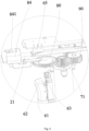
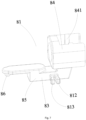
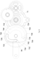
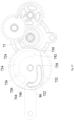
Figs. 24-28 illustrate schematic diagrams of state changes of a first driving device of the stapler as shown inFig. 21 . - In order to make the purpose, technical solutions and advantages of the invention clearer, the invention will be further described below in combination with the drawings and embodiments. It is to be understood that the specific embodiments described herein are for the purpose of explaining the invention only and are not intended to limit the invention. All other embodiments obtained by those of ordinary skill in the art based on the embodiments of the invention without creative efforts shall fall within the protection scope of the invention.
- The terms "proximal," "posterior," and "distal," "anterior" are used herein with reference to a clinician manipulating a surgical instrument. The terms "proximal" and "posterior" refer to portions relatively close to the clinician, and the terms "distal" and "anterior" refer to portions relatively far from the clinician. "Left" and "right" are referenced to the position of the surgical instrument as shown in
Fig. 1 , e.g., an end effector is on the "left" and a sleeve is on the "right". The terms "upper" and "lower" are referenced to the relative positions of a staple abutting seat and a staple cartridge seat of the end effector, specifically, the staple abutting seat is "upper", and the staple cartridge seat is "lower". It is to be understood that the orientation terms "proximal," "posterior," "distal," "anterior," "left," "right," "upper" and "lower" are defined for convenience of description, however, the surgical instrument may be used in many orientations and positions, and thus these terms expressing relative positional relationships are not intended to be limiting and absolute. - As shown in
Figs. 1-14 , astapler 100 according to a first embodiment, which does not fall within the scope of protection, includes anoperation assembly 10, arod assembly 20 extending longitudinally from the operation assembly and anend effector 30 disposed at one end of therod assembly 20. Theend effector 30 includes astaple cartridge seat 31 and astaple abutting seat 32 pivotally connected to thestaple cartridge seat 31, thestaple cartridge seat 31 is used for operably supporting the staple cartridge (not shown in the figure), thestaple abutting seat 32 is selectively movable between an open position and a closed position. Theoperation assembly 10 includes a body (not shown in the figure) and atransmission mechanism 11 mounted on the body. Therod assembly 20 includes amandrel 21 and asleeve 22 sleeving themandrel 21, one end of themandrel 21 is connected with a rack of a second driving device, and the other end of themandrel 21 is located in thesleeve 22; thesleeve 22 includes afirst end portion 23 connected to a first driving device and asecond end portion 24 connected to thestaple abutting seat 32 of theend effector 30, backward movement of thesleeve 22 enables thestaple abutting seat 32 to pivot upwards so as to open theend effector 30, and forward movement of thesleeve 22 enables thestaple abutting seat 32 to pivot downwards to close theend effector 30. Referring toFigs. 10 and 11 , thestaple abutting seat 32 is rotatably connected to thesecond end portion 24 of thesleeve 22, i.e., thestaple abutting seat 32 is connected to thesecond end portion 24 of thesleeve 22 and thestaple abutting seat 32 is rotatable relative to thesecond end portion 24 of thesleeve 22. It is to be noted that thestaple abutting seat 32 is rotatably connected to thesecond end portion 24 of thesleeve 22, so that forward and backward movement of thesleeve 22 drives thestaple abutting seat 32 to pivot belongs to a relevant art. - Referring to
Figs. 10-11 and15-20 , thesecond end portion 24 of thesleeve 22 is movably connected to thestaple abutting seat 32, and thestaple abutting seat 32 is driven to pivot upwards to open theend effector 30 when thesleeve 22 moves towards a proximal end; and thestaple abutting seat 32 is driven to pivot downwards to close theend effector 30 when thesleeve 22 moves towards a distal end . - In some embodiments, referring to
Figs. 15 and 16 , thesleeve 22 includes abody 15 and a drivingtube 29 which are connected, and the drivingtube 29 drives thestaple abutting seat 32 to pivot upwards or downwards to open or close theend effector 30. Thebody 15 and the drivingtube 29 are connected by a hinge or may be integrally formed. - The driving
tube 29 includes afirst driving portion 27 for driving thestaple abutting seat 32 to be opened and asecond driving portion 25 for driving thestaple abutting seat 32 to be closed. Thefirst driving portion 27 is a protruding portion disposed on the drivingtube 29, and the protruding portion obliquely extends along a lower right part; and thesecond driving portion 25 is a driving face at a distal end of the drivingtube 29. - Correspondingly, the
staple abutting seat 32 is provided with a first driven portion13 capable of being cooperated with the first drivingportion 27 and a second drivenportion 14 capable of being cooperated with thesecond driving portion 25. The first drivenportion 13 is a protruding portion disposed on thestaple abutting seat 32, and the protruding portion extends upwards; and the second drivenportion 14 is an abutting face at a proximal end of thestaple abutting seat 32. - Referring to
Figs. 17 and 18 , in some embodiments, a guide mechanism is further disposed between thestaple abutting seat 32 and thestaple cartridge seat 31, the guide mechanism includes apin 19 disposed on thestaple abutting seat 32 and a kidney-shapedgroove 17 formed in thestaple cartridge seat 31, and the kidney-shapedgroove 17 obliquely extends upwards in a direction from the proximal end to the distal end. - Referring to state changes of
Figs. 19-20 , when theend effector 30 needs to be opened, thebody 15 of thesleeve 22 pulls the drivingtube 29 to move towards the proximal end, the first drivingportion 27 on the drivingtube 29 abuts against the first drivenportion 13 on thestaple abutting seat 32, thepin 19 moves from a distal upper end of the kidney-shapedgroove 17 to a proximal lower end, thestaple abutting seat 32 pivots upwards, and theend effector 30 is opened. - Referring to state changes of Figs. 20-19, when the end effector needs to be closed, the
body 15 of thesleeve 22 pushes the drivingtube 29 to move towards the distal end, thesecond driving portion 25 on the drivingtube 29 abuts against the second drivenportion 14 on thestaple abutting seat 32, thepin 19 moves from the proximal lower end of the kidney-shapedgroove 17 to the distal upper end, thestaple abutting seat 32 pivots downwards, and theend effector 30 is closed. - The
stapler 100 further includes a cuttingknife assembly 40, the cuttingknife assembly 40 includes a cuttingknife 41 disposed in the staple cartridge and aknife pushing member 42 detachably connected to the cuttingknife 41, a part of theknife pushing member 42 is located in thesleeve 22 and connected to the other end of themandrel 21, and the other part of theknife pushing member 42 extends into theend effector 30 and is detachably connected to the cuttingknife 41. Referring toFigs. 3 and5 , theknife pushing member 42 is provided with a recess (not labeled), the cuttingknife 41 is provided with a protrusion (not labeled), and the recess and the protrusion cooperate to enable theknife pushing member 42 and the cuttingknife 41 to be assembled together. - In some embodiments, the
stapler 100 further includes atrigger 60, acircuit board assembly 50 and amotor 70. Thetrigger 60 and themotor 70 are electrically connected to thecircuit board assembly 50. The number of themotor 70 is one. Thecircuit board assembly 50 includes acircuit board 51 and acontrol module 52 electrically connected to thecircuit board 51. Thestapler 100 further includes a pressing holding mechanism (not shown in the figure), which is operated by the clinician before the cuttingknife assembly 40 is driven to move forwards, and after the pressing holding mechanism finishes working, the clinician may drive the cuttingknife assembly 40 to move forwards. - As shown in
Fig. 12 , in some embodiments, thecontrol module 52 includes adetection unit 53, amicro control unit 54, amotor driving unit 55, and amotor control unit 56. The detectingunit 53 is configured to detect a trigger signal of thetrigger 60 and transmit the signal to themicro control unit 54, themicro control unit 54 analyzes and processes the signal and transmits the signal to themotor driving unit 55, themotor driving unit 55 analyzes and processes the signal and transmits the signal to themotor control unit 56, and themotor control unit 56 sends an operation instruction to themotor 70 according to a received signal. - The
trigger 60 includes afirst button 61 and asecond button 62. Thefirst button 61 and thesecond button 62 are both electrically connected to thecontrol module 52. - The
trigger 60 further includes athird button 63 and afourth button 64, thethird button 63 and thefourth button 64 are symmetrically disposed, thethird button 63 and thefourth button 64 are both electrically connected to thecontrol module 52, and a same function is achieved no matter which of thethird button 63 and thefourth button 64 is pressed by the clinician. In some embodiments, thestapler 100 further includes an indication mechanism (not shown in the figure) electrically connected to thecontrol module 52, the indication mechanism includes five indication lamps, which are LED lamps. Thethird button 63, thefourth button 64, thecontrol module 52 and the indication mechanism form the pressing holding mechanism together to improve the pressing effect. The clinician presses thethird button 63 or thefourth button 64 and releases the same, thecontrol module 52 receives a signal sent by thethird button 63 or thefourth button 64 and instructs the indication mechanism to start working, one LED lamp is lighted every three seconds, when all the five LED lamps are in a lighting state, the indication mechanism finishes working, and at the moment, the clinician may operate thefirst button 61 to drive the cuttingknife assembly 40 to move forwards. If the clinician wants to drive the cuttingknife assembly 40 to move forwards before the indication mechanism finishes working, to save time, the following operation mode may be used: thethird button 63 or thefourth button 64 is pressed and released, thethird button 63 or thefourth button 64 is pressed and released again within 15 seconds, and at the moment, the clinician may operate thefirst button 61 to drive the cuttingknife assembly 40 to move forwards. The pressing holding mechanism finishes operation includes: thethird button 63 or thefourth button 64 is pressed and released instantly, and the indication mechanism starts to work until the work is finished. The operation of the press holding mechanism is terminated includes: thethird button 63 or thefourth button 64 is pressed and released instantly, and thethird button 63 or thefourth button 64 is pressed and released again instantly within 15 seconds. - In some embodiments, the
trigger 60 further includes afirst travel switch 65, asecond travel switch 66, athird travel switch 67, and afourth travel switch 68 electrically connected to thecontrol module 52, thefirst travel switch 65 is configured to detect whether the cuttingknife assembly 40 has moved forwards in place or not, thesecond travel switch 66 is configured to detect whether the cuttingknife assembly 40 has moved backwards in place or not, thethird travel switch 67 is configured to detect whether theend effector 30 has been closed in place or not, and thefourth travel switch 68 is configured to detect whether theend effector 30 has been opened in place or not. - The work process of the stapler 100 is as follows: (1) when the clinician presses the first button 61 and keeps a pressing state, the control module 52 receives a signal sent by pressing the first button 61 and then instruct the motor 70 to work, the motor 70 drives the transmission mechanism 11 to work, the transmission mechanism 11 drives the staple abutting seat 32 to pivot downwards so as to close the end effector 30, when the transmission mechanism 11 triggers the third travel switch 67, the control module 52 receives a signal and instructs the motor 70 to stop working, at the moment, the end effector 30 is closed in place, and the clinician releases the first button 61; (2) the clinician operates the pressing holding mechanism; (3) when the pressing holding mechanism finishes operation or the operation of the press holding mechanism is terminated, the clinician presses the first button 61 and keeps a pressing state, the control module 52 receives a signal sent by pressing the first button 61 and then instructs the motor 70 to work, the motor 70 drives the transmission mechanism 11 to work, the transmission mechanism 11 drives the cutting knife assembly 40 to move forwards to cut tissue, when the transmission mechanism 11 triggers the first travel switch 65, the control module 52 receives a signal and instructs the motor 70 to stop working, at the moment, the cutting knife assembly 40 moves forwards in place, and a process of cutting the tissue is finished; (4) the clinician releases the first button 61, the control module 52 receives a signal sent by releasing the first button 61 and instructs the motor 70 to continue to work (retract), the motor 70 drives the transmission mechanism 11 to work, the transmission mechanism 11 drives the cutting knife assembly 40 to move backwards, when the transmission mechanism 11 triggers the second travel switch 66, the control module 52 receives a signal and instructs the motor 70 to stop working, and at the moment, the cutting knife assembly 40 moves backwards in place; (5) the clinician presses the second button 62 and keeps a pressing state, the control module 52 receives a signal sent by pressing the second button 62 and then instructs the motor 70 to work, the motor 70 drives the transmission mechanism 11 to work, the transmission mechanism 11 drives the staple abutting seat 32 to pivot upwards so as to open the end effector 30, when the transmission mechanism 11 triggers the fourth travel switch 68, the control module 52 receives a signal and instructs the motor 70 to stop working, at the moment, the end effector 30 is opened in place, and the clinician releases the second button 62.
- The
transmission mechanism 11 includes a driving device, the driving device includes afirst driving device 80, asecond driving device 90 and afifth gear 71, and thefifth gear 71 is fixed to an output shaft of themotor 70. Or, the fifth gear is fixed to an output shaft of a gearbox driven by themotor 70, i.e., thefifth gear 71 is directly or indirectly connected with the output shaft of themotor 70. Thefifth gear 71 is a driving gear, or thefifth gear 71 is referred to as a front driving gear. Thefifth gear 71 is always connected with themotor 70 and driven by themotor 70 to rotate, and the connection includes direct connection and indirect connection. In other words, during the work process of thestapler 100, thefifth gear 71 is not disengaged from themotor 70, and thefifth gear 71 is always connected with themotor 70 and driven by themotor 70 to rotate. Thefirst driving device 80 is configured to drive theend effector 30 to be opened and closed, and thesecond driving device 90 is configured to drive the cuttingknife assembly 40 to move forwards and backwards. Themotor 70 drives thefifth gear 71 to rotate in a first direction or a second direction, and the first direction is opposite to the second direction. Thefirst driving device 80 and thesecond driving device 90 are both meshed with thefifth gear 71, and thefifth gear 71 rotates to enable thefirst driving device 80 or thesecond driving device 90 to work. When thefirst driving device 80 works, thefirst driving device 80 drives thesleeve 22 to move forwards and backwards, thereby pivoting thestaple abutting seat 32 to close and open theend effector 30; and when thesecond driving device 90 works, thesecond driving device 90 drives themandrel 21 to move forwards and backwards, thereby enabling the cuttingknife assembly 40 to move forwards and backwards. The driving device also includes arod assembly 20. In some embodiments, the driving device further includes amandrel 21. In some embodiments, the driving device further includes asleeve 22. - In some embodiments, the
first driving device 80 includes acompression ring assembly 81 and afirst gear assembly 82, thecompression ring assembly 81 includes a connectingmember 83 and acompression ring 84, the connectingmember 83 includes a connectingrod 85 and a protrudingcolumn 86 disposed at one end of the connectingrod 85, and thecompression ring 84 is disposed at the other end of the connectingrod 85. Thefirst gear assembly 82 includes afirst rod 87 and afirst gear 88 sleeving thefirst rod 87, thefirst rod 87 is fixed to a body (not shown in the figure) of theoperation assembly 10, and thefirst gear 88 rotates around thefirst rod 87. Thefirst gear 88 includes acam 89, when thefirst gear 88 rotates, thecam 89 rotates synchronously, and thefirst gear 88 is meshed with thefifth gear 71. Thecam 89 is provided with agroove 890 formed by sinking downward from a top surface thereof, and the protrudingcolumn 86 is located in thegroove 890. In some embodiments, thegroove 890 includes anarc groove 891 and astraight groove 892, two ends of thestraight groove 892 are defined as afirst end 893 and asecond end 894, respectively, two ends of thearc groove 891 are defined as athird end 895 and afourth end 896, respectively, and thesecond end 894 of thestraight groove 892 communicates with thethird end 895 of thearc groove 891, that is, thesecond end 894 of thestraight groove 892 is substantially thethird end 895 of thearc groove 891; 'communicate' means that a part of thegroove 890 is through with another part of thegroove 890 so that the protrudingcolumn 86 may move from a portion of thegroove 890 to another portion of thegroove 890. Specifically, 'communicate' means that thearc groove 891 is through with thestraight groove 892 so that the protrudingcolumn 86 may move from thearc groove 891 to thestraight groove 892, and thearc groove 891 communicates with thestraight groove 892 to form a non-closed groove as shown inFig. 8 , or a closed annular groove as shown inFig. 13 . Thefirst end portion 23 of thesleeve 22 is connected to thecompression ring 84, specifically, an outer wall of thefirst end portion 23 of thesleeve 22 is provided with a groove, an inner wall of thecompression ring 84 is provided with arib 841, the groove and therib 841 cooperate to assemble thesleeve 22 and thecompression ring 84 together, and thesecond end portion 24 of thesleeve 22 is movably connected to thestaple abutting seat 32. When the motor 70 drives the fifth gear 71 to rotate in the first direction, the fifth gear 71 drives the first gear 88 to rotate in the second direction, the cam 89 also rotates synchronously in the second direction, during a rotation of the cam 89, the protruding column 86 moves from the first end 893 of the straight groove 892 to the second end 894 of the straight groove 892 along the straight groove 892, during the process, the compression ring assembly 81 moves forwards, the compression ring assembly 81 drives the sleeve 22 to move forwards, and when the sleeve 22 moves forwards, the second end portion 24 of the sleeve 22 drives the staple abutting seat 32 to rotate downwards for closing; when the motor 70 drives the fifth gear 71 to rotate in the second direction, the fifth gear 71 drives the first gear 88 to rotate in the first direction, the cam 89 also rotates synchronously in the first direction, during the rotation of the cam 89, the protruding column 86 moves from the second end 894 of the straight groove 892 to the first end 893 of the straight groove 892 along the straight groove 892, during the process, the compression ring assembly 81 moves backwards, the compression ring assembly 81 drives the sleeve 22 to move backwards, and when the sleeve 22 moves backwards, the second end portion 24 of the sleeve 22 drives the staple abutting seat 32 to rotate upwards to realize opening. Thesleeve 22 is the output member offirst gear 88. - When the protruding
column 86 is located in thearc groove 891 and moves back and forth along thearc groove 891, since a radial distance from any point of the same inner wall of thearc groove 891 to thefirst rod 87 is not changed, therefore, when thecam 89 rotates, the distance of the protrudingcolumn 86 in a lengthwise direction with respect to thefirst rod 87 is not changed, that is, the rotation of thecam 89 does not drive thecompression ring assembly 81 to move forwards and backwards. Since the radial distance from any point of the same inner wall of thestraight groove 892 to thefirst rod 87 increases in a direction away from the first rod 87 (i.e., in a direction from thefirst end 893 to thesecond end 894 inFig. 8 ) and decreases in a direction closer to the first rod 87 (i.e., in a direction from thesecond end 894 to thefirst end 893 inFig. 8 ), therefore, thecompression ring assembly 81 is driven to move forwards when the protrudingcolumn 86 moves in thestraight groove 892 in the direction away from thefirst rod 87, and thecompression ring assembly 81 is driven to move backwards when the protrudingcolumn 86 moves in thestraight groove 892 in the direction closer to thefirst rod 87. As shown inFig. 13 , thearc groove 891 communicates with thestraight groove 892 to form the closed annular groove, and the portion that functions of thestraight groove 892 occupies half of its length. It is to be noted that the movement of the protrudingcolumn 86 in thegroove 890 is a relative movement, which is achieved by the rotation of thecam 89. - In some embodiments, the
second driving device 90 includes arack 91, asecond gear assembly 92, and athird gear assembly 93. Thesecond gear assembly 92 includes asecond rod 94 and asecond gear 95 sleeving thesecond rod 94, thesecond rod 94 is fixed to the body of theoperation assembly 10, thesecond gear 95 rotates around thesecond rod 94, and thesecond gear 95 is meshed with thefifth gear 71; and thesecond gear 95 includes a firsttoothed portion 951 and a tooth-missingportion 952 that are disposed adjacently in a circumferential direction, the firsttoothed portion 951 and the tooth-missingportion 952 have a first boundary and a second boundary therebetween, and the tooth-missingportion 952 includes anon-toothed portion 953 and a secondtoothed portion 954 that are disposed adjacently in the vertical direction (i.e., the axial direction). Thesecond gear 95 is always kept meshed with thefifth gear 71 by the firsttoothed portion 951 and the secondtoothed portion 954. Thethird gear assembly 93 includes athird rod 96, athird gear 97 and afourth gear 98 sleeving thethird rod 96, thethird rod 96 is fixed to the body of theoperation assembly 10, thethird gear 97 and thefourth gear 98 rotate around thethird rod 96, thethird gear 97 and thefourth gear 98 are integrally formed, thethird gear 97 and thefourth gear 98 have different diameters, thethird gear 97 is configured to be meshed with a portion, parallel to thenon-toothed portion 953, of the firsttoothed portion 951 of thesecond gear 95, and thefourth gear 98 is meshed with therack 91. Therack 91 is the output member of thesecond gear 95, and a diameter of thefourth gear 98 is greater than a diameter of thethird gear 97. - Since the
fifth gear 71 connected to the output shaft of themotor 70 has a first rotation speed, but the movement of therack 91 requires a second speed, in order to convert the first rotation speed of thefifth gear 71 into the second speed of the movement of therack 91, thethird gear 97 and afourth gear 98 need to be disposed between thefifth gear 71 and therack 91 for adjustment. Since the diameters of thethird gear 97 and thefourth gear 98 are different, linear speeds at which thethird gear 97 and thefourth gear 98 rotate are also different, and thus, thethird gear 97 and thefourth gear 98 may convert the first rotation speed of thefifth gear 71 into the second speed of the movement of therack 91. - The working process of the
stapler 100 will be described in detail below. - An operator presses the first button 61 and keeps the pressing state, the control module 52 receives a signal generated by pressing the first button 61 and sends an operation instruction to the motor 70, the motor 70 drives the fifth gear 71 to rotate in the first direction, the fifth gear 71 drives the first gear 88 to rotate in the second direction, the cam 89 also synchronously rotates in the second direction, during the rotation of the cam 89, the protruding column 86 of the compression ring assembly 81 moves from the first end 893 of the straight groove 892 to the second end 894 of the straight groove 892 (i.e. the third end 895 of the arc groove 891) along the straight groove 892, so that the compression ring assembly 81 is driven to move forwards, the compression ring assembly 81 drives the sleeve 22 to move forwards, and at the moment, the sleeve 22 drives the staple abutting seat 32 to rotate downwards to further close the end effector 30; on the other hand, during the process that the protruding column 86 moves from the first end 893 of the straight groove 892 to the second end 894 of the straight groove 892 along the straight groove 892, the fifth gear 71 drives the second gear 95 to rotate in the second direction, during the process, an intersection position of the second gear 95 and the third gear 97 is at the non-toothed portion of the second gear 95, so that the rotation of the second gear 95 does not drive the third gear 97 to rotate, thereby allowing the cutting knife 41 to remain stationary during the closing of the end effector 30.
- When the
compression ring assembly 81 advances to a certain position, afirst tab 812 on thecompression ring assembly 81 triggers thethird travel switch 67 at a front stop point of the forward movement of thecompression ring assembly 81, i.e., theend effector 30 is closed in place, and at the moment, the protrudingcolumn 86 is located at thesecond end 894 of the straight groove 892 (i.e., thethird end 895 of the arc groove 891). Thecontrol module 52 receives a signal sent by thethird travel switch 67 and sends an instruction of stopping operation to themotor 70, and themotor 70 stops rotating. The clinician does not hear a sound of the operation of themotor 70 and releases thefirst button 61 and operates the pressing holding mechanism. - After the pressing holding mechanism finishes working or the operation of the pressing holding mechanism is terminated, the clinician presses the first button 61 and keeps the pressing state, the control module 52 receives a signal generated by pressing the first button 61 and analyzes the signal, the control module 52 generates an operation instruction to the motor 70 according to the analyzed signal, the motor 70 drives the fifth gear 71 to continue to rotate in the first direction, the fifth gear 71 drives the second gear 95 to rotate in the second direction, the intersection position of the second gear 95 and the third gear 97 is rotated to the portion, parallel to the non-toothed portion 953, of the first toothed portion 951 from the non-toothed portion 953 of the second gear 95, the first toothed portion 951 of the second gear 95 is meshed with the third gear 97 and drives the third gear 97 to rotate in the first direction, the fourth gear 98 also rotates in the first direction due to the fact that the third gear 97 and the fourth gear 98 are integrally formed, the fourth gear 98 drives the rack 91 to move forwards, the rack 91 drives the mandrel 21 to move forwards, the mandrel 21 drives the knife pushing member 42 to move forwards, and the knife pushing member 42 drives the cutting knife 41 to move forwards to cut tissue; on the other hand, the fifth gear 71 drives the first gear 88 to rotate in the second direction, the protruding column 86 moves from the second end 894 of the straight groove 892 (i.e., the third end 895 of the arc groove 891) to the fourth end 896 of the arc groove 891 along the arc groove 891, at the moment, the rotation of the cam 89 does not drive the compression ring assembly 81 to move forwards and backwards, thereby allowing the end effector 30 to remain closed during the forward movement of the cutting knife 41.
- When the
rack 91 advances to a certain position, the protrudingportion 99 on therack 91 contacts with thefirst travel switch 65, a position of thefirst travel switch 65 is the front stop point of the forward movement of the cuttingknife 41, namely the position of cutting completion, and at the moment, the protrudingcolumn 86 is located at thefourth end 896 of thearc groove 891; the meshing point of thesecond gear 95 and thethird gear 97 is located close to the first boundary of the firsttoothed portion 951 and the tooth-missingportion 952 of thesecond gear 95, that is, if thesecond gear 95 continues to rotate in the second direction, the firsttoothed portion 951 of thesecond gear 95 will be disengaged from thethird gear 97. The control module 52 receives a signal generated by the first travel switch 65 and sends an instruction of stopping operation to the motor 70, the motor 70 stops rotating, the clinician releases the first button 61, the control module receives a signal generated by releasing the first button 61 and sends an operation instruction to the motor 70, the motor drives the fifth gear 71 to rotate in the second direction, the fifth gear 71 drives the second gear 95 to rotate in the first direction, the first toothed portion 951 of the second gear 95 drives the third gear 97 to rotate in the second direction, the fourth gear 98 also rotates in the second direction due to the fact that the third gear 97 and the fourth gear 98 are integrally formed, the fourth gear 98 drives the rack 91 to move backwards, the rack 91 drives the mandrel 21 to move backwards, the mandrel 21 drives the knife pushing member 42 to move backwards, and the knife pushing member 42 drives the cutting knife 41 to move backwards, so that retracting is realized; and on the other hand, the fifth gear 71 drives the first gear 88 to rotate in the first direction, the protruding column 86 moves from the fourth end 896 of the arc groove 891 to the third end 895 of the arc groove 891 (i.e., the second end 894 of the straight groove 892) along the arc groove 891, and at the moment, the rotation of the cam 89 does not drive the compression ring assembly 81 to move forwards and backwards, thereby allowing the end effector 30 to remain closed during the backward movement of the cutting knife 41. - When the
rack 91 moves backwards to a certain position, the protrudingportion 99 on therack 91 contacts with thesecond travel switch 66, the position of thesecond travel switch 66 is a rear stop point of the backward movement of the cuttingknife 41, and at the moment, the protrudingcolumn 86 is located at thethird end 895 of the arc groove 891 (i.e., thesecond end 894 of the straight groove 892); and the meshing point of thesecond gear 95 and thethird gear 97 is located close to the second boundary of the firsttoothed portion 951 and the tooth-missingportion 952 of thesecond gear 95, that is, if thesecond gear 95 continues to rotate in the first direction, the firsttoothed portion 951 of thesecond gear 95 will be disengaged from thethird gear 97. Thecontrol module 52 receives a signal sent by thesecond travel switch 66 and sends an instruction of stopping operation to themotor 70, at the moment, themotor 70 stops working, and retracting is finished. After retracting is finished, the clinician presses the second button 62 and keeps the pressing state, the control module 52 receives a signal generated by pressing the second button 62 and sends an operation instruction to the motor 70, the motor 70 drives the fifth gear 71 to rotate in the second direction, the fifth gear 71 drives the first gear 88 to rotate in the first direction, the cam 89 also synchronously rotates in the first direction, during the rotation of the cam 89, the protruding column 86 moves from the second end 894 of the straight groove 892 to the first end 893 of the straight groove 892 along the straight groove 892, the compression ring assembly 81 moves backwards, the compression ring assembly 81 drives the sleeve 22 to move backwards, and at the moment, the sleeve 22 drives the staple abutting seat 32 to rotate upwards to further open the end effector 30; and on the other hand, the fifth gear 71 drives the second gear 95 to rotate in the first direction, the first toothed portion 951 of the second gear 95 is disengaged from the third gear 97, namely, in the process that the protruding column 86 moves from the second end 894 of the straight groove 892 to the first end 893 of the straight groove 892 along the straight groove 892, the boundary of the second gear 95 and the third gear 97 is located at the non-toothed portion 953 of the second gear 95, so that the rotation of the second gear 95 does not drive the third gear 97 to rotate, thereby allowing the cutting knife 41 to remain stationary during an opening process of the end effector 30. - When the
compression ring assembly 81 retreats to a certain position, asecond tab 813 on thecompression ring assembly 81 contacts with thefourth travel switch 68 at the rear stop point of the backward movement of thecompression ring assembly 81, i.e., theend effector 30 is opened in place, and at the moment, the protrudingcolumn 86 is located at thefirst end 893 of thestraight groove 892. Thecontrol module 52 receives a signal sent by thefourth travel switch 68 and sends an instruction of stopping operation to themotor 70, and at the moment, themotor 70 stops working. - In the embodiment, the
first tab 812 and thesecond tab 813 are disposed on thecompression ring 84, or disposed on the connectingrod 85, as shown inFig. 7 . In other embodiments, thefirst tab 812 and thesecond tab 813 may also be disposed on thefirst gear 88, as shown inFig. 14 . - In the embodiment, the
first gear 88 includes an effective stroke structure and an idle stroke structure, thefirst gear 88 includes thearc groove 891 and thestraight groove 892, thestraight groove 892 is the effective stroke structure, and thearc groove 891 is the idle stroke structure. When the protrudingcolumn 86 moves in thestraight groove 892, thefirst gear 88 drives thecompression ring assembly 81 to move forwards; and when the protrudingcolumn 86 moves in thearc groove 891, thefirst gear 88 does not drive thecompression ring assembly 81 to move forwards. Thesecond gear 95 includes an effective stroke structure and an idle stroke structure, thesecond gear 95 includes the firsttoothed portion 951 and the tooth-missingportion 952, the tooth-missingportion 952 includes the secondtoothed portion 954 and thenon-toothed portion 953, thenon-toothed portion 953 is the idle stroke structure, and a portion, parallel to thenon-toothed portion 953, of the firsttoothed portion 951 is the effective stroke structure. When thethird gear 97 is meshed with the portion, parallel to thenon-toothed portion 953, of the firsttoothed portion 951 of thesecond gear 95, thesecond gear 95 drives thethird gear 97 to move; and when thethird gear 97 is meshed with thenon-toothed portion 953 of thesecond gear 95, thesecond gear 95 does not drive thethird gear 97 to move. - As can be seen, in the embodiment, the tooth-missing
portion 952 includes the secondtoothed portion 954 and thenon-toothed portion 953 which are disposed adjacently in a vertical direction (axial direction). Although the firsttoothed portion 951 is disposed integrally, the firsttoothed portion 951 includes afirst tooth portion 959 and asecond tooth portion 957 which are different in meshing targets in the vertical direction (axial direction): thefirst tooth portion 959 is always meshed with thefifth gear 71, and thesecond tooth portion 957 is selectively meshed with thethird gear 97. Thefirst tooth portion 959 and thesecond tooth portion 957 are disposed adjacently in the vertical direction, and the boundary of thefirst tooth portion 959 and thesecond tooth portion 957 is located at the same height as the boundary of the secondtoothed portion 954 and thenon-toothed portion 953. - The
first tooth portion 959 and the secondtoothed portion 954 are disposed adjacently in the circumferential direction. Thefirst tooth portion 959 and the secondtoothed portion 954 are equal in height. A top surface (virtual surface) of thefirst tooth portion 959 is located at the same height as a top surface of the secondtoothed portion 954. In the circumferential direction, thefirst tooth portion 959 and the secondtoothed portion 954 form a complete gear, which is named a sixth gear for convenience of description, and the sixth gear is always meshed with thefifth gear 71 and is driven to rotate by thefifth gear 71. Thesecond tooth portion 957 and thenon-toothed portion 953 are disposed adjacently in the circumferential direction. The secondtoothed portion 957 and thenon-toothed portion 953 are equal in height. A bottom surface (virtual surface, the same as the top surface of the first tooth portion 959) of thesecond tooth portion 957 is located at the same height as a bottom surface (the same as the top surface of the second toothed portion 954) of thenon-toothed portion 953. The secondtoothed portion 957 is an effective stroke structure, and thenon-toothed portion 953 is an idle stroke structure. The sixth gear forms a driving gear of thesecond tooth portion 957. The sixth gear is driven by thefifth gear 71 to rotate, when the sixth gear rotates to enable thesecond tooth portion 957 of the firsttoothed portion 951 to be meshed with thethird gear 97, thefifth gear 71 sequentially drives thesecond tooth portion 957, thethird gear 97 and thefourth gear 98 to rotate through the sixth gear, so that therack 91 is driven to linearly move; and when the sixth gear rotates to couple thenon-toothed portion 953 and thethird gear 97, thefifth gear 71 and the sixth gear may rotate under the driving of themotor 70, but thethird gear 97 and thefourth gear 98 do not rotate, and therack 91 does not output linear movement. `Coupling' means that a part of teeth of thethird gear 97 is located in a spatial region where thenon-toothed portion 953 is located without contacting with thenon-toothed portion 953, and thethird gear 97 is not driven in the process of coupling with thenon-toothed portion 953 since there is no contact with the non-toothed portion 953 (including not meshing due to fact that thenon-toothed portion 953 has no teeth). - In some embodiments of the invention, the idle stroke means that the driving device has no motion output, i.e., does not drive the cutting knife or the end effector, when the driving device has motion input, i.e., is driven. The idle stroke structure is a structure that is included in a component of the driving device and that may realize the idle stroke. Effective stroke means that the driving device has motion output, i.e., drives the cutting knife or the end effector, when the driving device has motion input, i.e., is driven. The effective stroke structure is a structure that is included in a component of the driving device and that may realize the effective stroke.
- The driving device includes a driving gear, in the embodiment, the
fifth gear 71 is the driving gear, the driving gear is always connected with themotor 70 and is driven by themotor 70, and themotor 70 drives thefirst driving device 80 and thesecond driving device 90 by the driving gear (the fifth gear 71). Or the fifth gear is referred to as a front driving gear. - The
first driving device 80 includes a first driving gear driven by themotor 70. In some embodiments, themotor 70 drives the first driving gear by the front driving gear. In the embodiment, the first driving gear is thefirst gear 88. Thefirst driving device 80 further includes a first effective stroke structure (straight groove 892) and a first idle stroke structure (arc groove 891). In some embodiments, the first effective stroke structure (straight groove 892) and the first idle stroke structure (arc groove 891) are disposed on the end face of thefirst gear 88. Thefirst driving device 80 also includes a first output member, which in the embodiment is thesleeve 22. - Thus, when the front driving gear drives the first effective stroke structure by the first driving gear of the
first driving device 80, the first output member is driven by the first effective stroke structure to move, and when the front driving gear drives the first idle stroke structure by the first driving gear of thefirst driving device 80, the first output member is not driven by the first idle stroke structure and does not move. In some embodiments, when thefifth gear 71 drives the first effective stroke structure (straight groove 892) by thefirst gear 88 of thefirst driving device 80, thesleeve 22 is driven by the first effective stroke structure to move, and when thefifth gear 71 drives the first idle stroke structure (arc groove 891) by thefirst gear 88 of thefirst driving device 80, thesleeve 22 is not driven by the first idle stroke structure and does not move. - The
second driving device 90 includes a second driving gear driven by themotor 70. In some embodiments, the motor drives the second driving gear by the front driving gear. In the embodiment, the second driving gear is a sixth gear formed by thefirst tooth portion 959 and the secondtoothed portion 954 of thesecond gear 95. Thesecond driving device 90 further includes a second effective stoke structure (thesecond tooth portion 957, disposed adjacent to thenon-toothed portion 953, of the first toothed portion 951) and a second idle stoke structure (the non-toothed portion 953). Thesecond driving device 90 also includes a second output member, which in the embodiment is therack 91. - Thus, when the front driving gear drives the second effective stroke structure by the second driving gear of the
second driving device 90, the rack linearly moves, and when the front driving gear drives the second idle stroke structure by the second driving gear of thesecond driving device 90, therack 91 does not move. Specifically, when thefifth gear 71 drives thesecond tooth portion 957 by the sixth gear, therack 91 linearly moves; and when thefifth gear 71 drives thenon-toothed portion 953 by the sixth gear, the rack does not move. - That is, one driving gear (the fifth gear 71) may drive the
sleeve 22 to move through thefirst driving device 80 including the first effective stroke structure (the straight groove 892), and also may drive therack 91 to move through thesecond driving device 90 including the second effective stroke structure (the second tooth portion 957), and the structural design is quite reasonable. In some embodiments, the movement of thesleeve 22 and the movement of therack 91 are both linear movements. - The
fifth gear 71 is always connected with themotor 70 and driven by themotor 70, thefifth gear 71 rotates as long as themotor 70 is started to rotate a motor shaft, and thesleeve 22 is not driven by thefirst driving device 80 and therack 91 is not driven by thesecond driving device 90 to move simultaneously in the rotation process of thefifth gear 71, so that an incorrect use of the stapler may be avoided. In some embodiments, themotor 70 alternatively drives one of the first effective stroke structure and the second effective stroke structure. That is, during driving, themotor 70 may only drive one of the first effective stroke structure and the second effective stroke structure. Therefore, themotor 70 does not drive therack 91 when driving thesleeve 22, and does not drive thesleeve 22 when driving therack 91, so that the stapler works reasonably. - The driving device has two states: in the first state, the
motor 70 drives the first effective stroke structure and the second idle stroke structure; and in the second state, themotor 70 drives the second effective stroke structure and first idle stroke structure. - That is, in the first state, the driving gear (the fifth gear 71) drives the first effective stroke structure of the
first driving device 80 and the second idle stroke structure of thesecond driving device 90, so that the driving gear does not drive therack 91 to move when driving thesleeve 22 to move, and the driving gear (the fifth gear 71) does not drive the cuttingknife assembly 40 to move while driving theend effector 30 to be opened or closed. - In the second state, the driving gear (the fifth gear 71) drives the second effective stroke structure of the
second driving device 90 and the first idle stroke structure of thefirst driving device 80, so that the driving gear (the fifth gear 71) does not drive thesleeve 22 to move when driving the cuttingknife assembly 40 to move, and the driving gear (the fifth gear 71) does not drive theend effector 40 to be opened or closed while driving the cuttingknife assembly 30 to move. - It can be seen that the driving gear (the fifth gear 71) may drive both the
first driving device 80 and thesecond driving device 90, but the driving gear does not drive both the first effective stroke structure of thefirst driving device 80 and the second effective stroke structure of thesecond driving device 90, and the design is quite reasonable. Meanwhile, the two states of the driving device satisfy the logic of action of theend effector 30 and the cuttingknife assembly 40. - As can be seen, the
groove 890 of thecam 89 includes thearc groove 891 and thestraight groove 892, the protrudingcolumn 86 is located in thegroove 890, so that theend effector 30 may be driven to be opened and closed, and meanwhile, theend effector 30 may remain closed during movement of the cuttingknife assembly 40. Thesecond gear 95 includes the firsttoothed portion 951 and the tooth-missingportion 952, the firsttoothed portion 951 includes thesecond tooth portion 957, and the tooth-missingportion 952 includes thenon-toothed portion 953, thereby driving the cuttingknife assembly 40 to move forwards and backwards and allowing the cuttingknife assembly 40 to remain stationary during opening and closing of theend effector 30. Thestapler 100 of the invention is provided with onemotor 70 that may drive thefirst driving work 80 to work, thereby driving theend effector 30 to be opened and closed, and also may drive thesecond driving device 90 to work, thereby driving the cuttingknife assembly 40 to move forwards and backwards; and meanwhile, the logic of action between theend effector 30 and the cuttingknife assembly 40 is satisfied. In some embodiments, in the process that themotor 70 drives the driving device to work, the effective stroke and the idle stroke are realized by the structure of the components of the driving device, a relative position between the components of the driving device for realizing the effective stroke and the idle stroke does not need to be changed, the relative position does not need to be changed, means that the protruding column is always located in the groove and there is no relative linear displacement between the second gear and the third gear, the structure and the interconnection relationship of the components are simple, the probability of generating assembly errors is small in the process of assembling the components, and thestapler 100 is not prone to malfunction in the working process. - In a second embodiment, which does not fall within the scope of protection, the first gear may be replaced with a first gear as shown in
Fig. 13 , thefirst gear 88 includes acam 89, thecam 89 is provided with agroove 890 formed by sinking downward from the top surface thereof, and the protrudingcolumn 86 of the connectingmember 83 is located in thegroove 890. Thegroove 890 includes anarc groove 891 and astraight groove 892, two ends of thearc groove 891 communicate through thestraight groove 892, that is, thestraight groove 892 and thearc groove 891 form a closed ring together; 'communicate' means that a part of thegroove 890 is through with another part of thegroove 890 so that the protrudingcolumn 86 may move from a part of thegroove 890 to another part of thegroove 890; and two ends of thestraight groove 892 are defined as afirst end 893 and asecond end 894, respectively, and the intermediate position between thefirst end 893 and thesecond end 894 is a middle. During the rotation of thecam 89, the protrudingcolumn 86 moves from the middle of thestraight groove 892 to thesecond end 894 of thestraight groove 892 along thestraight groove 892, during the process, thecompression ring assembly 81 moves forwards, thecompression ring assembly 81 drives thesleeve 22 to move forwards, and when thesleeve 22 moves forwards, thesecond end portion 24 of thesleeve 22 drives thestaple abutting seat 32 to rotate downwards for realizing closing; and during the rotation of thecam 89, the protrudingcolumn 86 moves from thesecond end 894 of thestraight groove 892 to the middle of thestraight groove 892 along thestraight groove 892, during the process, thecompression ring assembly 81 moves backwards, thecompression ring assembly 81 drives thesleeve 22 to move backwards, and when thesleeve 22 moves backwards, thesecond end portion 24 of thesleeve 22 drives thestaple abutting seat 32 to rotate upwards for realizing opening. When the protrudingcolumn 86 is located in thearc groove 891 and moves back and forth along thearc groove 891, since the radial distance from any point of the same inner wall of thearc groove 891 to thefirst rod 87 is not changed, when thecam 89 rotates, the distance of the protrudingcolumn 86 in the lengthwise direction with respect to thefirst rod 87 is not changed, that is, the rotation of thecam 89 does not drive thecompression ring assembly 81 to move forwards and backwards. In the embodiment, the protrudingcolumn 86 moves from the middle ofstraight groove 892 to the second end 894 (one end of the arc groove ) of thestraight groove 892 along thestraight groove 892, thereby realizing closing of theend effector 30; the protrudingcolumn 86 then moves from thesecond end 894 of thestraight groove 892 to thefirst end 893 of the straight groove 892 (the other end of the arc groove 891) along thearc groove 891, thereby allowing theend effector 30 to remain closed during the process of forward movement of the cuttingknife 41; and the protrudingcolumn 86 moves from thefirst end 893 of thestraight groove 892 to thesecond end 894 of thestraight groove 892 along thearc groove 891, thereby allowing theend effector 30 to remain closed during the process of backward movement of the cuttingknife 41; and the protrudingcolumn 86 moves fromsecond end 894 of thestraight groove 892 to the middle of thestraight groove 892 along thestraight groove 892, thereby allowing theend effector 30 to be opened. -
Figs. 21-28 illustrate a surgical instrument according to a third embodiment of the invention. - Referring to
Figs. 21-23 , the embodiment relates to a surgical instrument, in particular to a stapler, similar to the first embodiment. - In some embodiments, the surgical instrument is a surgical stapler, the surgical stapler includes a driving device driven by a power assembly. The driving device includes a first driving assembly and a first motion conversion assembly, wherein the first driving assembly includes a first effective stroke structure and a first idle stroke structure, the driving device has a first state and a second state, in the first state, the power assembly is engaged with the first effective stroke structure, and the first effective stroke structure drives the first motion conversion assembly; and in the second state, the power assembly is coupled with the first idle stroke structure, and the first motion conversion assembly is disengaged from a driving of the power assembly.
- The first driving assembly comprises a first driving member and a rotating
member 720, the first effective stroke structure and the first idle stroke structure are both disposed on the rotatingmember 720, and in the first state, the first driving member and the rotatingmember 720 are both engaged with the power assembly; and in the second state, only the first driving member in the first driving member and the rotatingmember 720 is engaged with the power assembly. - The first effective stroke structure is a
toothed portion 724, the first idle stroke structure is anon-toothed portion 730, and the toothed portion 723 and thenon-toothed portion 730 are disposed adjacently; and the first driving member is afirst driving gear 732. - The power assembly comprises a motor and a front driving gear driven by the motor, and in the first state, the front driving gear is meshed with the
toothed portion 724 and thefirst driving gear 732 simultaneously; and in the second state, the front driving gear is coupled with thenon-toothed portion 730, and is meshed with thefirst driving gear 732. - In some embodiments, the surgical stapler includes a transmission mechanism, an end actuator driven by the transmission mechanism, and a cutting knife assembly, wherein the transmission mechanism comprises a surgical instrument driving device and a sleeve, a proximal end of the sleeve is connected with the surgical instrument driving device, a distal end of the sleeve is connected with the end actuator, the surgical instrument driving device includes an end actuator driving device, the end actuator driving device includes the above-mentioned driving device, in response to the motor rotating in a first direction, the driving device drives the sleeve to move forwards so as to drive the end actuator to be closed; in response to the motor rotating in the second direction, the drive device drives the sleeve to move backwards so as to drive the end actuator to be opened.
- Similar to the first embodiment, the surgical instrument includes a driving assembly (a
motor 70 and afifth gear 71 driven by the motor 70), an end effector and a cutting knife assembly driven by the driving assembly through a driving device. The driving device includes a first driving device and a second driving device. The first driving device drives the end effector, and the second driving device drives the cutting knife assembly. Thus, the first driving device is referred to as the end effector driving device, and the second driving device is referred to as the cutting knife assembly driving device. - Similar to the first embodiment, the first driving device includes a first effective stroke structure and a first idle stroke structure. The second driving device includes a second effective stroke structure and a second idle stroke structure. The
motor 70 alternatively drives one of the first effective stroke structure and the second effective stroke structure. That is, during use of the surgical instrument, themotor 70 either drives the first effective stroke structure, thereby driving the end effector to be opened or closed, or the second effective stroke structure, thereby driving the cutting knife assembly to move forwards (advance) or backwards (retract), and errors in the working process of the stapler are avoided. - In some embodiments, the driving device has two states: in a first work state, the
motor 70 drives the first effective stroke structure and is coupled with the second idle stroke structure; and in a second work state, themotor 70 drives the second effective stroke structure and is coupled with the first idle stroke structure. That is, in the first work state, themotor 70 drives the end effector to be opened or closed without driving the cutting knife assembly, and in the second work state, themotor 70 drives the cutting knife assembly to advance or retract without driving the end effector. Coupling includes a direct coupling and also includes an indirect coupling. Similarly, driving includes a direct driving and also includes an indirect driving. - Similar to the first embodiment, the surgical instrument in operation is operated in the following steps during a normal use process.
- In S1, an output shaft of the
motor 70 rotates in a first direction, and themotor 70 drives the first effective stroke structure and is coupled with the second idle stroke structure. - In S2, the output shaft of the
motor 70 continues to rotate in the first direction, and themotor 70 drives the second effective stroke structure and is coupled with the first idle stroke structure. - In S3, the output shaft of the
motor 70 rotates in a second direction, the second direction is opposite to the first direction, and themotor 70 drives the second effective stroke structure and is coupled with the first idle stroke structure. - In S4, the
motor 70 continues to rotate in the second direction, and themotor 70 drives the first effective stroke structure and is coupled with the second idle stroke structure. - Therefore, during a normal use process of the surgical instrument in operation, the output shaft of the
motor 70 is reversed (rotates in the first direction and the second direction respectively), and in each rotation direction of themotor 70, the first work state and the second work state are switched, so that the driving device is fully utilized, the structure of the driving device is simplified on the premise that the logic action relation between the end effector and the cutting knife assembly is satisfied, and the design is quite reasonable. - The surgical instrument performs step S1 such that the driving device drives the end effector to be closed, thereby clamping tissue.
- The surgical instrument performs step S2 such that the driving device drives the cutting knife assembly to advance, thereby cutting the tissue.
- The surgical instrument performs step S3 such that the driving device drives the cutting knife assembly to retract, thereby resetting the cutting knife assembly.
- The surgical instrument performs step S4 such that the driving device drives the end effector to be opened, thereby releasing the tissue.
- It can be seen that the driving device of the surgical instrument is quite reasonable in design, so that the driving device is fully utilized, and meanwhile, the functions required by the normal work of the surgical instrument are completely realized.
- It is to be noted that the term "normal" work means that no other unexpected conditions, such as jamming of the cutting knife assembly, occur during the operation. The surgical instrument is deservedly designed with emergency devices to cope with unexpected conditions of the surgical instrument during the operation, but these emergency devices are not within the scope of the invention and not be described in detail.
- Similar to the first embodiment, the driving device further includes a front driving gear, the front driving gear is always connected with the
motor 70 and is driven by themotor 70, and the front driving gear drives the first driving device and the second driving device. The front driving gear of the driving device is thefifth gear 71. As long as themotor 70 is started such that its motor shaft rotates, the front driving gear (fifth gear 71) may drive one of the first effective stroke structure and the second effective stroke structure without driving both structures simultaneously. Themotor 70 and the front driving gear are referred to as a power assembly. Therefore, the driving device of the invention realizes switching between the first effective stroke structure and the second effective stroke structure without disposing an additional clutch device, thereby not only simplifying the structure of the driving device, but also avoiding the instability caused by clutch operation and greatly improving the safety of the surgical instrument. - The second driving device in the embodiment has the same structure as the second driving device of the first embodiment.
- In some embodiments, referring back to
Fig. 9 , the second driving device includes a second driving gear which is always meshed with thefifth gear 71 and is driven by themotor 70 through thefifth gear 71. Thus, the second driving gear is always connected with themotor 70 indirectly and driven by themotor 70. A sixth gear formed by afirst tooth portion 959 of a firsttoothed portion 951 and a secondtoothed portion 954 forms a second driving gear, and thefifth gear 71 drives the second driving gear to rotate. The second driving device includes a second effective stoke structure and a second idle stoke structure, the second effective stoke structure is asecond tooth portion 957 of the firsttoothed portion 951, and the second idle stoke structure is anon-toothed portion 953. The second driving device further includes arack 91 driven by the second effective stoke structure. The details will not be elaborated herein. - It can be seen that the second driving device includes a second driving assembly, and a second motion conversion assembly engaged with the second driving assembly. In some embodiments, the second driving assembly includes a second driving member being a second driving gear, i.e., the sixth gear formed by the
first tooth portion 959 of the firsttoothed portion 951 and the secondtoothed portion 954. The second motion conversion assembly includes a second transmission member and a second output member. In some embodiments, the second transmission member includes thesecond tooth portion 957 and thenon-toothed portion 953, and the second output member includes therack 91. The second driving member and the second transmission member are integrally disposed, so that the second driving member and the second transmission member synchronously move. - The
second tooth portion 957 is the effective stroke structure, thenon-toothed portion 953 is the idle stroke structure, so that, in the second driving device, the second effective stroke structure and the second idle stroke structure are disposed on the second motion conversion assembly, and particularly on the second transmission member of the second motion conversion assembly. The second effective stroke structure is engaged with the second output member, which moves, and the second output member is not driven when the second idle stroke structure is coupled with the second output member. In some embodiments, when thesecond tooth portion 957 is engaged with therack 91, thesecond tooth portion 957 drives therack 91 to move linearly; and when thenon-toothed portion 953 is coupled with therack 91, therack 91 is not driven. It can be seen that the second transmission member formed by thesecond tooth portion 957 and thenon-toothed portion 953 is always engaged with thefifth gear 71 through the second driving gear, regardless of whether thesecond tooth portion 957 is engaged with therack 91 or thenon-toothed portion 953 is coupled with the rack. - It is to be noted that in some embodiments of the invention, coupling means that no motion is transmitted between two components; whereas engaging means that two components are connected and motion may be transmitted. It is to be noted that, in some embodiments of the invention, coupling includes the direct coupling and the indirect coupling, when a component A and a component B in a same driving "chain" are adjacent to each other and do not contact each other, so that no motion is transmitted, the component A and the component B are the direct coupling, other components directly or indirectly driving the component A in the same driving "chain" are indirectly coupled with the component B, and the component A is indirectly coupled with other components directly or indirectly driven by the component B in the same driving "chain". Engaging includes a direct engaging and an indirect engaging, when a component C and a component D in the same driving "chain" are connected and motion may be transmitted, the component C and the component D are the direct engaging, other components directly or indirectly driving the component C in the same driving "chain" are indirectly engaged with the component D, and the component C is indirectly engaged with other components directly or indirectly driven by the component D in the same driving "chain". For example, the motor, the front driving gear, the first driving gear, the first driving assembly and the first motion conversion assembly form a driving "chain", and the motor, the front driving gear, the second driving gear, the second driving assembly and the second motion conversion assembly also form a driving "chain".
- Although a speed reduction assembly ncluding a
third gear 97 and afourth gear 98 is further disposed between thesecond tooth portion 957 and therack 91, the speed reduction assembly only achieves speed reduction and does not affect the substantial operation principle of the second motion conversion assembly. - The first driving device in the embodiment is different in partial structure from the first embodiment.
- As can be seen from the above description, in the first embodiment, the first driving device includes the first driving assembly and the first motion conversion assembly driven by the first driving assembly. The first motion conversion assembly includes a first transmission member and a first output member engaged with the first transmission member. In some embodiments, the first driving assembly includes the
first gear 88. The first transmission member includes astraight groove 892 and anarc groove 891, and the first output member includes a protrudingcolumn 96. The first output member may be a direct output member of the first motion conversion assembly, such as the protrudingcolumn 96; and the first output member may also be an indirect output member of the first motion conversion assembly, such as asleeve 22 or other subsequent output members. - In the first embodiment, the
straight groove 892 is an effective stroke structure, thearc groove 891 is an idle stroke structure, that is, in the first embodiment, the effective stroke structure and the idle stroke structure are disposed on the motion conversion assembly. The motion conversion component realizes conversion of two different motion forms. - While in the embodiment, the first driving device is driven by the power assembly, and the first driving device includes the driving assembly and the motion conversion assembly driven by the first driving assembly. The motion conversion assembly includes a driving member and an output member. The driving assembly includes the first effective stroke structure and the first idle stroke structure. The first driving device has a first state and a second state. In the first state, when the power assembly is engaged with the first effective stroke structure, the driving assembly drives the motion conversion assembly, and the output member moves; and in the second state, the power assembly is coupled with the first idle stroke structure, the motion conversion assembly is disengaged from the driving of the power assembly, the driving assembly does not drive the motion conversion assembly, and the output member is not driven. That is, in the embodiment, the effective stroke structure and the idle stroke structure are disposed on the driving assembly. The driving assembly only transmits its previous form of motion without effecting the conversion of the form of motion.
- For the first driving device of the embodiment, compared with the first embodiment, although in one embodiment, the effective stroke structure and the idle stroke structure are disposed on the driving assembly, in the other embodiment, the effective stroke structure and the idle stroke structure are disposed on the motion conversion assembly, there are some similarities between the invention conception of the embodiment and the first embodiment, i.e., the effective stroke structure and the idle stroke structure are disposed in a transmission chain of the driving device, so that the output member may also be driven or not driven as required even if the motor is driven.
- In some embodiments, the driving assembly includes a first driving member and a rotating
member 720, the effective stoke structure and the idle stoke structure are disposed on the rotatingmember 720, the first driving member and the rotatingmember 720 have two states, in a first state, the effective stoke structure of the rotatingmember 720 and the first driving member are synchronously driven by themotor 70, the rotatingmember 720 drives the motion conversion assembly, and the output member moves; and in a second state, themotor 70 is coupled with the idle stoke structure, the motor drives the first driving member and does not drive the rotatingmember 720, the rotatingmember 720 does not drive the motion conversion assembly, and the output member is not driven. When themotor 70 drives the first effective stroke structure, the motion conversion assembly converts rotation of the rotatingmember 720 into linear motion of the output member, and the linear motion of the output member further drives the end effector to be opened or closed. When themotor 70 is coupled with the first idle stoke structure, themotor 70 does not drive the sleeve to move. - In some embodiments" the first driving member is a
first driving gear 732 which is always connected with themotor 70 and driven by themotor 70. More specifically, thefirst driving gear 732 is always meshed with thefifth gear 71, and thefifth gear 71 is always connected with themotor 70 and driven by themotor 70, so that thefirst driving gear 732 is indirectly connected with themotor 70 and driven by themotor 70. - The first effective stroke structure is a
toothed portion 724, and the first idle stroke structure is anon-toothed portion 730. Thetoothed portion 724 and thenon-toothed portion 730 are disposed on a circumferential face of the rotatingmember 720. Thetoothed portion 724 and thenon-toothed portion 730 are disposed adjacently. The outer diameter of thenon-toothed portion 730 is smaller than the outer diameter of thetoothed portion 724, and the outer diameter of thetoothed portion 724 includes the dimension, in a radial direction of the rotatingmember 720, of teeth. - The motion conversion assembly includes a transmission member and the output member, and the transmission member is disposed on the rotating
member 720. The transmission member includes afirst groove 722, and the output member includes a protrudingcolumn 86. A radial distance between thefirst groove 722 and a rotation center of the rotatingmember 720 increases or decreases along thefirst groove 722, and the protrudingcolumn 86 slides in thefirst groove 722 to convert rotation of the rotatingmember 720 into linear motion of the protrudingcolumn 86. The protrudingcolumn 86 is a direct output member. The protrudingcolumn 86 is connected with a connecting rod, a compression ring and the sleeve in sequence, which is the same as the first embodiment. The sequential connection means that: the connecting rod is connected with the protrudingcolumn 86, the compression ring is connected with the connecting rod, and the sleeve is connected with the compression ring. The sleeve may drive the end effector to be opened or closed. The sleeve may be considered an indirect output member. - In the first state, the
toothed portion 724 of the rotatingmember 720 and thefirst driving gear 732 are simultaneously meshed with thefifth gear 71, the rotatingmember 720 and thefirst driving gear 732 are driven by thefifth gear 71 to synchronously rotate, the rotatingmember 720 is driven by thefifth gear 71 to rotate, i.e., the protrudingcolumn 86 may be driven to linearly move through the matching of thefirst groove 722 and the protrudingcolumn 86, and finally, the end effector is driven to be closed or opened; in the second state, only thefirst driving gear 732 is meshed with thefifth gear 71 and driven by themotor 70, while thenon-toothed portion 730 of the rotatingmember 720 is coupled with thefifth gear 71 and indirectly coupled with themotor 70, thenon-toothed portion 730 of the rotatingmember 720 may not be meshed with thefifth gear 71, and the rotatingmember 720 does not drive the end effector to be closed or opened. The meaning of coupling is consistent with the definition in the preceding text. It is also to be noted that, consistent with the foregoing description, coupling includes the direct coupling and the indirect coupling. - When the clinician uses the surgical instrument, the clinician typically operates a pressing holding mechanism to press the tissue after the end effector is closed and before the cutting knife assembly advances, during which the tissue is thinned and the end effector is further closed. To ensure that the driving gear always applies force to the end effector to keep the end effector in a closed state during a process of pressing tissue, referring to
Fig. 24 , in the embodiment, the first effective stroke structure includes a first portion and a second portion which are adjacently disposed, the first portion drives the end effector to execute a first stage of closing to clamp the tissue, and the second portion drives the end effector to execute a second stage of closing to press the tissue. In some embodiments, thetoothed portion 724 includes a stroke drivingtooth portion 726 and a pressingholding tooth portion 728 which are disposed adjacently. When the front driving gear drives the stroke drivingtooth portion 726, the protrudingcolumn 86 slides in thefirst groove 722 to drive the end effector to be closed. The pressingholding tooth portion 728 is meshed with the front driving gear during pressing holding, so that the front driving gear always applies a certain action force on the end effector by the pressingholding tooth portion 728 during pressing holding, thereby avoiding an accidental release of the end effector. Since a closing stroke of the end effector is small during the process of pressing tissue, in the embodiment, the pressingholding tooth portion 728 includes one to two tooth portions. - The
first groove 722 includes a first section and a second section communicated with the first section, corresponding to that "the first effective stroke structure includes the first portion and a second portion" disposed adjacently. The first portion is engaged with the power assembly, so that the first output member is engaged with the first section; and the second portion is engaged with the power assembly, so that the first output member is engaged with the second section. In some embodiments, the stroke drivingtooth portion 726 is engaged with thefifth gear 71 and themotor 70 such that the protrudingcolumn 86 moves in in the first section, thereby driving the end effector to execute the first stage of closing; and the pressingholding tooth portion 728 is engaged with thefifth gear 71 and themotor 70 such that the protrudingcolumn 86 moves in the second section, thereby driving the end effector to execute the first stage of closing. - The end effector is driven to be closed for clamping tissue when the protruding
column 86 moves in the first section, and is driven to be further closed to press the tissue when the protrudingcolumn 86 moves in the second section. - In some embodiments, the
first groove 722 also includes a third section communicating with the second section, and the second section is located between the first section and the third section. The third section disposed may provide a certain margin for the sliding of the protrudingcolumn 86 in thefirst groove 722, so as to avoid jamming. - The
first driving gear 732 and the rotatingmember 720 are overlapped, In some embodiments, thefirst driving gear 732 and the rotatingmember 720 are overlapped in the axial direction. It is convenient to mesh thefirst driving gear 732 and thetoothed portion 724 of the rotatingmember 720 with thefifth gear 71 at the same time. - A first end face of the
first driving gear 732 is adjacent to a second end face of the rotatingmember 720, one of the two end faces is provided with asecond arc groove 734, the other is provided with aprotrusion 736 extending into thesecond arc groove 734, and a circle center of thesecond arc groove 734 is located on the rotation axis of thefirst driving gear 732. Theprotrusion 736 may slide in thesecond arc groove 734. On one hand, the matching of theprotrusion 736 with thesecond arc groove 734 may guarantee that thefirst driving gear 732 and the rotatingmember 720 are overlapped; on the other hand, theprotrusion 736 may slide in the arc groove, so that in the second state, the rotatingmember 720 does not rotate with thefirst driving gear 732, the operation of the first idle stroke is guaranteed, and therefore, the rotatingmember 720 does not drive the end effector to be closed or opened when the driving device drives the cutting knife assembly to move. - Returning to
Figs. 7 and8 , in the first embodiment, thefirst gear 88 drives the sleeve to move linearly to drive the end effector to be opened or closed through sliding of the protrudingcolumn 86 in thestraight groove 892, so that thefirst gear 88 applies an action force to the sleeve and thus the end effector. As can be known from the principle of action force and reverse force, the end effector, in turn, indirectly applies a certain reverse force to thefirst gear 88. When the cutting knife assembly cuts the tissue, the end effector clamps the tissue, and the clamping of the tissue is realized by the cooperation of the cutting knife assembly and the end effector in the cutting process. In some embodiments, the cutting knife assembly is provided with an upper lug portion, a lower lug portion and a connecting portion connected to the upper lug portion and the lower lug portion, and the upper lug portion, the lower lug portion and the connecting portion are fixedly connected or integrally formed. During cutting, the upper lug portion of the cutting knife assembly moves in the groove of a staple abutting seat of the end effector, and the lower lug portion moves in the groove of a staple cartridge seat. The upper lug portion has a traction effect on the staple abutting seat through the groove of the staple abutting seat, and the lower lug portion has a traction effect on the staple cartridge seat through the groove of the staple cartridge seat, so that mutual clamping of the staple abutting seat and the staple cartridge seat in the cutting process is realized. The reverse force of the tissue to the end effector is transmitted inversely through thefirst gear 88 to thefifth gear 71 and themotor 70, which reduces the power transmitted by thefifth gear 71 through the second driving device to the cutting knife assembly, thereby affecting the cutting efficiency of the cutting knife assembly. - Referring to
Figs. 21 to 23 , in the embodiment, theprotrusion 736 may freely slide in thesecond arc groove 734. Thus, there is a loose fit between thefirst driving gear 732 and the rotatingmember 720. Thus, even if the end effector clamps the tissue when the cutting knife assembly cuts the tissue, the reverse force applied by the end effector to the rotatingmember 720 is not transmitted to thefifth gear 71 or only a small portion of the reverse force is transmitted to thefifth gear 71 due to the loose fit between the rotatingmember 720 and thefirst driving gear 732, thereby avoiding or reducing the influences on the cutting efficiency of the cutting knife assembly and improving the cutting efficiency of the cutting knife assembly. - The width of the
protrusion 736 is smaller than a width of thesecond arc groove 734. Thus, theprotrusion 736 may slide in thesecond arc groove 734, and the function of the second state is realized. Those skilled in the art may appreciate that the width of theprotrusion 736 is equal to the width of thesecond arc groove 734, and all the solutions similar to or the same as the present embodiments are covered within the protection scope of the invention. - When the driving device drives the second effective stroke structure, the
protrusion 736 slides in thesecond arc groove 734. In the embodiment, a circumferential extension length of thesecond arc groove 734 is greater than a circumferential extension length required by the second effective stroke. Margin is provided for movement of theprojection 736 in thesecond arc groove 734. Those skilled in the art may appreciate that the circumferential extension length of thesecond arc groove 734 is equal to the circumferential extension length of the second effective stroke, and all the solutions similar to or the same as the present embodiments are covered in the protection scope of the invention. - The
protrusion 736 abuts against an end portion of thesecond arc groove 734 so that the rotatingmember 720 and thefirst driving gear 732 are switched from the second state to a ready position of the first state. In some embodiments, after retracting is completed, theprotrusion 736 abuts against ahead end 742 of thesecond arc groove 734, so that thetoothed portion 724 of the rotatingmember 720 and the teeth of thefirst driving gear 732 are aligned up and down, and at the moment, if themotor 70 rotates, the rotatingmember 720 and thefirst driving gear 732 are synchronously meshed with thefront driving gear 71, so as to ensure the subsequent smooth opening of the end effector to release the tissue. - Therefore, in the embodiment, the
toothed portion 724 of the rotatingmember 720 is the first effective stroke structure, and thenon-toothed portion 730 of the rotatingmember 720 is the first idle stroke structure. Thefirst driving gear 732 is always meshed with thefifth gear 71 and is driven by themotor 70, so that the effective stroke and the idle stroke are conveniently switched, and the structural design is reasonable. - The associated work process of the surgical instrument of the embodiment will now be described with reference to
Figs. 24-27 . - As shown in
Fig. 24 , at the moment, the end effector is in an open state and the cutting knife assembly is in an initial position. In the first driving device, the protrudingcolumn 86 is located at afirst end 738 of thefirst groove 722, theprotrusion 736 is located at ahead end 742 of thesecond arc groove 734, and thetoothed portion 724 of the rotatingmember 720 and thefirst driving gear 732 are simultaneously meshed with the driving gear (the fifth gear 71). - At the moment, if the clinician determines that the end effector has been aligned with the tissue to be cut, the clinician starts the
motor 70, themotor 70 rotates in the first direction to drive the driving gear (the fifth gear 71) to rotate, the rotatingmember 720 and thefirst driving gear 732 are in a first state, and the driving gear (the fifth gear 71) rotates to simultaneously drive the rotatingmember 720 and thefirst driving gear 732 to rotate. In the process, there is no relative rotation of the rotatingmember 720 and thefirst driving gear 732, and thus, theprotrusion 736 remains at thehead end 742 of thesecond arc groove 734; while rotation of the rotatingmember 720 drives the protrudingcolumn 86 to move in thefirst groove 722 from afirst end 738 toward asecond end 740, the end effector is gradually closed, and the first driving device reaches the position shown inFig. 25 . - At the position shown in
Fig. 25 , the driving gear (the fifth gear 71) is still meshed with thetoothed portion 724, in some embodiments, the driving gear (the fifth gear 71) is still meshed with the pressingholding tooth portion 728 of thetoothed portion 724. At the moment, the clinician may operate the pressing holding mechanism, during which the driving gear (the fifth gear 71) simultaneously drives the pressingholding tooth portion 728 and thefirst driving gear 732, the protrudingcolumn 86 moves a short distance further toward thesecond end 740, and the end effector is further closed to reach the position shown inFig. 26 . - In the position shown in
Fig. 26 , the end effector has pressed the tissue, the rotatingmember 720 and thefirst driving gear 732 are switched from the first state to the second state, the driving gear (the fifth gear 71) is disengaged from thetoothed portion 724 of the rotatingmember 720, and the driving gear (the fifth gear 71) is only meshed with thefirst driving gear 732. At the moment, the clinician may operate the cutting knife assembly, themotor 70 continues to rotate in the first direction, themotor 70 drives the cutting knife assembly to advance through the same second driving device (only part of which is shown inFig. 26 ) as in the first embodiment, so that the cutting knife assembly moves from an initial position to a final position, during the process, thenon-toothed portion 730 is coupled with the driving gear (the fifth gear 71), the driving gear (the fifth gear 71) does not drive the end effector to move through thenon-toothed portion 730, but the driving gear (the fifth gear 71) drives thefirst driving gear 732 of the first driving device to rotate, and theprotrusion 736 is driven to slide in thesecond arc groove 734 from ahead end 742 toward atail end 744 to reach the position shown inFig. 27 . - At the position shown in
Fig. 27 , the cutting assembly is at the final position and the tissue is cut. At the moment, the clinician may operate themotor 70 to rotate reversely, i.e., in the second direction opposite to the first direction, themotor 70 drives the cutting knife assembly to retract through the same second driving device (only part of which is shown inFig. 27 ) as in the first embodiment, so that the cutting knife assembly retracts to the initial position from the final position, during which thenon-toothed portion 730 is coupled with the driving gear (the fifth gear 71), the driving gear (the fifth gear 71) does not drive the end effector to move through thenon-toothed portion 730, but the driving gear (the fifth gear 71) drives thefirst driving gear 732 of the first driving device to rotate reversely, and theprotrusion 736 is driven to slide in thesecond arc groove 734 towards thehead end 742, and when theprotrusion 736 abuts against thehead end 742 of thesecond arc groove 734, thetoothed portion 724 of the rotatingmember 720 and the tooth portion of thefirst driving gear 732 are aligned up and down, and theprotrusion 736 reaches the position shown inFig. 28 . - At the position shown in
Fig. 28 , the clinician may operate themotor 70 such that themotor 70 continues to rotate reversely, the driving gear (the fifth gear 71) begins to drive the rotatingmember 720 and thefirst driving gear 732 to simultaneously rotate reversely, theprotrusion 736 remains at thehead end 742 of thesecond arc groove 734, and the protrudingcolumn 86 moves in thefirst groove 722 in a direction towards thefirst end 738, thereby driving the end effector to be opened, returning to the state shown inFig. 24 . Thus, a complete operation of the surgical instrument is realized, during which the surgical instrument sequentially realizes closing of the end effector for clamping the tissue, advancing of the cutting knife assembly for cutting the tissue, retracting of the cutting knife assembly, and opening of the end effector for loosening the tissue. - In the second to third embodiments, except for the technical features already described in the embodiments and the technical features that may be substituted with the above-described technical features, other technical features in the above-described embodiments are in the same part as in the first embodiment and are not repeated.
- In summary, the
stapler 100 of the invention is provided with onemotor 70 that driving thefirst driving work 80 to work, thereby driving theend effector 30 to be opened and closed, and can also drive thesecond driving device 90 to work, thereby driving the cuttingknife assembly 40 to move forwards and backwards. Thestapler 100 of the invention is small in size and low in cost, and in addition, onemotor 70 enables thestapler 100 to be small in overall weight and flexible to operate by the clinician. Single-motor driving is achieved by disposing the gear structure in the driving device, and the first driving device and the second driving device are simple in structure.
Claims (13)
- A driving device, driven by a power assembly, the driving device comprising a first driving assembly and a first motion conversion assembly, wherein the first driving assembly comprises a first effective stroke structure and a first idle stroke structure, the driving device has a first state and a second state, in the first state, the power assembly is engaged with the first effective stroke structure, and the first effective stroke structure drives the first motion conversion assembly; and in the second state, the power assembly is coupled with the first idle stroke structure, and the first motion conversion assembly is disengaged from a driving of the power assembly, characterized in that:the first driving assembly comprises a first driving member and a rotating member (720), the first effective stroke structure and the first idle stroke structure are both disposed on the rotating member (720), and in the first state, the first driving member and the rotating member (720) are both engaged with the power assembly; and in the second state, only the first driving member in the first driving member and the rotating member (720) is engaged with the power assembly;wherein the first effective stroke structure is a toothed portion (724), the first idle stroke structure is a non-toothed portion (730), and the toothed portion (723) and the non-toothed portion (730) are disposed adjacently; and the first driving member is a first driving gear (732);wherein the power assembly comprises a motor and a front driving gear driven by the motor, and in the first state, the front driving gear is meshed with the toothed portion (724) and the first driving gear (732) simultaneously; and in the second state, the front driving gear is coupled with the non-toothed portion (730), and is meshed with the first driving gear (732).
- The driving device as claimed in claim 1, wherein the first motion conversion assembly comprises a first transmission member and a first output member, and in the first state, the first transmission member drives the first output member to move; and in the second state, the first output member is not driven.
- The driving device as claimed in claim 1, wherein the first driving member and the rotating member (720) are overlapped, one of the first driving member and the rotating member (720) is provided with an arc groove, the other is provided with a protrusion (736) extending into the arc groove, and a circle center of the arc groove is located on a rotation axis of the first driving member.
- The driving device as claimed in claim 3, wherein a width of the protrusion (736) is smaller than a width of the arc groove; or wherein the protrusion (736) abuts against an end portion of the arc groove, so that the rotating member (720) and the first driving member are switched from the second state to a ready position of the first state.
- The driving device as claimed in claim 1, wherein the first motion conversion assembly comprises a first groove (722) and a protruding column, a radial distance between the first groove (722) and a rotation center of the rotating member (720) increases or decreases along the first groove (722), and the protruding column is slidable in the first groove (722) to convert rotation of the rotating member (720) into linear movement of the protruding column; preferably wherein the first groove is disposed on the rotating member.
- A surgical stapler, comprising a transmission mechanism (11), an end actuator driven by the transmission mechanism (11), and a cutting knife assembly (40), wherein the transmission mechanism (11) comprises a surgical instrument driving device and a sleeve (22), a proximal end of the sleeve (22) is connected with the surgical instrument driving device, a distal end of the sleeve is connected with the end actuator, the surgical instrument driving device comprises an end actuator driving device, the end actuator driving device comprises the driving device as claimed in any one of claims 1-5, wherein in response to the motor (70) rotating in a first direction, the driving device drives the sleeve (22) to move forwards so as to drive the end actuator to be closed; and wherein in response to the motor rotating in the second direction, the drive device drives the sleeve (22) to move backwards so as to drive the end actuator to be opened.
- The surgical stapler as claimed in claim 6, wherein the first effective stroke structure comprises a first portion and a second portion which are disposed adjacently, the first portion drives the end actuator to execute a first stage of closing to clamp tissue, and the second portion drives the end actuator to execute a second stage of closing to press the tissue.
- The surgical stapler as claimed in claim 7, wherein the first motion conversion assembly comprises a first transmission member and a first output member engaged with the first transmission member, and the first transmission member comprises a first section and a second section which are disposed adjacently; the first portion is engaged with the power assembly, so that the first output member is engaged with the first section; and the second portion is engaged with the power assembly, so that the first output member is engaged with the second section.
- The surgical stapler as claimed in claim 8, wherein the first transmission member also comprises a third section adjacent to the second section, and the second section is located between the first section and the third section.
- The surgical stapler as claimed in claim 6, wherein the surgical stapler comprises a cutting knife assembly driving device, which drives a cutting knife assembly (40) to move forwards or backwards; wherein the cutting knife assembly driving device is driven by a power assembly.
- The surgical stapler as claimed in claim 10, wherein the cutting knife assembly driving device comprises a second effective stroke structure and a second idle stroke structure, and the power assembly drives one of the first effective stroke structure and the second effective stroke structure.
- The surgical stapler as claimed in claim 10, wherein the cutting knife assembly driving device comprises a second driving assembly and a second motion conversion assembly engaged with the second driving assembly, the second motion conversion assembly comprises a second transmission member and a second output member, the second transmission member comprises a second effective stroke structure and a second idle stroke structure, the cutting knife assembly driving device has a third state and a fourth state, and in the third state, the second effective stroke structure is engaged with the second output member; and in the fourth state, the second idle stroke structure is coupled with the second output member.
- The surgical stapler as claimed in claim 12, wherein the second driving assembly comprises a second driving member, the second driving member and the second transmission member move synchronously, and in the third state and the fourth state, the second transmission member is always engaged with the power assembly through the second driving member; or
wherein the second effective stroke structure is a toothed portion disposed on the second transmission member, the second idle stroke structure is a non-toothed portion (953) disposed on the second transmission member, and the second output member is a rack (91).
Priority Applications (1)
| Application Number | Priority Date | Filing Date | Title |
|---|---|---|---|
| EP25152433.6A EP4516260A3 (en) | 2019-05-01 | 2020-04-30 | Driving device, surgical instrument, and operation method of surgical instrument |
Applications Claiming Priority (3)
| Application Number | Priority Date | Filing Date | Title |
|---|---|---|---|
| CN201910367363 | 2019-05-01 | ||
| CN201910367362 | 2019-05-01 | ||
| PCT/CN2020/088444 WO2020221355A1 (en) | 2019-05-01 | 2020-04-30 | Driving device, surgical instrument, and operation method thereof |
Related Child Applications (2)
| Application Number | Title | Priority Date | Filing Date |
|---|---|---|---|
| EP25152433.6A Division EP4516260A3 (en) | 2019-05-01 | 2020-04-30 | Driving device, surgical instrument, and operation method of surgical instrument |
| EP25152433.6A Division-Into EP4516260A3 (en) | 2019-05-01 | 2020-04-30 | Driving device, surgical instrument, and operation method of surgical instrument |
Publications (4)
| Publication Number | Publication Date |
|---|---|
| EP3964138A1 EP3964138A1 (en) | 2022-03-09 |
| EP3964138A4 EP3964138A4 (en) | 2023-01-18 |
| EP3964138C0 EP3964138C0 (en) | 2025-02-26 |
| EP3964138B1 true EP3964138B1 (en) | 2025-02-26 |
Family
ID=73029668
Family Applications (2)
| Application Number | Title | Priority Date | Filing Date |
|---|---|---|---|
| EP20798923.7A Active EP3964138B1 (en) | 2019-05-01 | 2020-04-30 | Driving device, surgical instrument, and operation method thereof |
| EP25152433.6A Withdrawn EP4516260A3 (en) | 2019-05-01 | 2020-04-30 | Driving device, surgical instrument, and operation method of surgical instrument |
Family Applications After (1)
| Application Number | Title | Priority Date | Filing Date |
|---|---|---|---|
| EP25152433.6A Withdrawn EP4516260A3 (en) | 2019-05-01 | 2020-04-30 | Driving device, surgical instrument, and operation method of surgical instrument |
Country Status (11)
| Country | Link |
|---|---|
| US (2) | US11819210B2 (en) |
| EP (2) | EP3964138B1 (en) |
| JP (1) | JP7279198B2 (en) |
| KR (2) | KR20240104186A (en) |
| CN (2) | CN118021398A (en) |
| CA (2) | CA3138575A1 (en) |
| ES (1) | ES3021861T3 (en) |
| HU (1) | HUE070807T2 (en) |
| IL (2) | IL287713B2 (en) |
| MX (2) | MX2021013362A (en) |
| WO (2) | WO2020221357A1 (en) |
Families Citing this family (10)
| Publication number | Priority date | Publication date | Assignee | Title |
|---|---|---|---|---|
| US12349902B2 (en) | 2020-07-09 | 2025-07-08 | Covidien Lp | Powered handle assembly for surgical devices |
| CN112402019B (en) * | 2020-11-30 | 2023-05-05 | 重庆金山医疗机器人有限公司 | Surgical robot |
| CN118697401A (en) * | 2020-12-11 | 2024-09-27 | 江苏风和医疗器材股份有限公司 | A surgical instrument |
| CN113520503B (en) * | 2021-08-24 | 2022-05-27 | 常州安康医疗器械有限公司 | Electric endoscope anastomat capable of preventing false triggering |
| WO2023051269A1 (en) * | 2021-09-30 | 2023-04-06 | 江苏风和医疗器材股份有限公司 | Electric surgical instrument |
| CN116262062A (en) * | 2021-12-15 | 2023-06-16 | 宁波海泰科迈医疗器械有限公司 | Electric stapling instrument |
| CN116491998B (en) * | 2022-01-25 | 2025-11-07 | 江苏风和医疗器材股份有限公司 | Surgical instruments |
| KR102923591B1 (en) * | 2023-04-14 | 2026-02-04 | 가톨릭대학교 산학협력단 | Stapler for suturing dermal layer implant |
| CN118415702B (en) * | 2024-05-11 | 2025-05-06 | 江苏博朗森思医疗器械有限公司 | Electric anastomat |
| CN118924368A (en) * | 2024-08-27 | 2024-11-12 | 湖南思捷泰克医疗科技有限公司 | Closing component and electric anastomat |
Family Cites Families (38)
| Publication number | Priority date | Publication date | Assignee | Title |
|---|---|---|---|---|
| EP0625335B1 (en) * | 1993-04-20 | 1997-11-19 | United States Surgical Corporation | Surgical stapler |
| US8286845B2 (en) * | 2000-11-27 | 2012-10-16 | Boston Scientific Scimed, Inc. | Full thickness resection device control handle |
| US7364061B2 (en) * | 2003-09-29 | 2008-04-29 | Ethicon Endo-Surgery, Inc. | Surgical stapling instrument incorporating a multistroke firing position indicator and retraction mechanism |
| US10041822B2 (en) * | 2007-10-05 | 2018-08-07 | Covidien Lp | Methods to shorten calibration times for powered devices |
| US7128254B2 (en) * | 2004-09-07 | 2006-10-31 | Ethicon Endo-Surgery, Inc. | Surgical stapling instrument incorporating a multistroke firing mechanism having a rotary slip-clutch transmission |
| US7959050B2 (en) * | 2005-07-26 | 2011-06-14 | Ethicon Endo-Surgery, Inc | Electrically self-powered surgical instrument with manual release |
| US9237891B2 (en) * | 2005-08-31 | 2016-01-19 | Ethicon Endo-Surgery, Inc. | Robotically-controlled surgical stapling devices that produce formed staples having different lengths |
| US20110295295A1 (en) | 2006-01-31 | 2011-12-01 | Ethicon Endo-Surgery, Inc. | Robotically-controlled surgical instrument having recording capabilities |
| US20120292367A1 (en) * | 2006-01-31 | 2012-11-22 | Ethicon Endo-Surgery, Inc. | Robotically-controlled end effector |
| US8931682B2 (en) * | 2007-06-04 | 2015-01-13 | Ethicon Endo-Surgery, Inc. | Robotically-controlled shaft based rotary drive systems for surgical instruments |
| US7658311B2 (en) | 2007-06-22 | 2010-02-09 | Ethicon Endo-Surgery, Inc. | Surgical stapling instrument with a geared return mechanism |
| CN101475066B (en) | 2009-01-25 | 2011-04-20 | 江阴市江南轻工机械有限公司 | Brick carton shaping apparatus of brick carton filling machine |
| US9877720B2 (en) * | 2010-09-24 | 2018-01-30 | Ethicon Llc | Control features for articulating surgical device |
| CN201879763U (en) | 2010-12-21 | 2011-06-29 | 南京迈迪欣医疗器械有限公司 | Disposable rotary cutting anastomat |
| US9629629B2 (en) * | 2013-03-14 | 2017-04-25 | Ethicon Endo-Surgey, LLC | Control systems for surgical instruments |
| JP6325086B2 (en) * | 2013-04-16 | 2018-05-16 | エシコン・エンド−サージェリィ・インコーポレイテッドEthicon Endo−Surgery,Inc. | Surgical instrument comprising a closing drive and a firing drive operated from the same rotatable output |
| US9649110B2 (en) * | 2013-04-16 | 2017-05-16 | Ethicon Llc | Surgical instrument comprising a closing drive and a firing drive operated from the same rotatable output |
| CN104224254B (en) * | 2013-06-20 | 2016-03-30 | 瑞奇外科器械(中国)有限公司 | Surgical operating instrument and driving device thereof |
| US20140014704A1 (en) * | 2013-09-16 | 2014-01-16 | Ethicon Endo-Surgery, Inc. | Medical Device Having An Improved Coating |
| US20140014707A1 (en) | 2013-09-16 | 2014-01-16 | Ethicon Endo-Surgery, Inc. | Surgical Stapling Instrument Having An Improved Coating |
| US9713466B2 (en) | 2014-05-16 | 2017-07-25 | Covidien Lp | Adaptor for surgical instrument for converting rotary input to linear output |
| US10456132B2 (en) | 2014-06-25 | 2019-10-29 | Ethicon Llc | Jaw opening feature for surgical stapler |
| US9895148B2 (en) | 2015-03-06 | 2018-02-20 | Ethicon Endo-Surgery, Llc | Monitoring speed control and precision incrementing of motor for powered surgical instruments |
| US10390825B2 (en) * | 2015-03-31 | 2019-08-27 | Ethicon Llc | Surgical instrument with progressive rotary drive systems |
| US9872725B2 (en) | 2015-04-29 | 2018-01-23 | Ethicon Llc | RF tissue sealer with mode selection |
| US10117650B2 (en) * | 2015-05-05 | 2018-11-06 | Covidien Lp | Adapter assembly and loading units for surgical stapling devices |
| US10194911B2 (en) * | 2015-06-26 | 2019-02-05 | Ethicon Llc | Surgical stapler with ready state indicator |
| US10456134B2 (en) | 2015-06-26 | 2019-10-29 | Ethicon Llc | Surgical stapler with reversible motor |
| US10709495B2 (en) * | 2015-11-13 | 2020-07-14 | Ethicon Llc | Dual step bailout for motorized RF device |
| JP7086854B2 (en) * | 2016-04-01 | 2022-06-20 | エシコン エルエルシー | Handle assembly of surgical instruments with reconfigurable grips |
| CN105943104B (en) | 2016-05-24 | 2019-04-09 | 山东威瑞外科医用制品有限公司 | Intracavitary Endo-GIA cutting driving device for cutter |
| CN105997171B (en) | 2016-06-08 | 2018-08-21 | 宁波维尔凯迪医疗器械有限公司 | A kind of hand-reset structure and the stapler with the structure |
| US10667806B2 (en) | 2016-12-07 | 2020-06-02 | Ethicon, Inc. | Applicator instruments with reconfigurable handles for dispensing surgical fasteners |
| US10405932B2 (en) * | 2016-12-20 | 2019-09-10 | Ethicon Llc | Robotic endocutter drivetrain with bailout and manual opening |
| CN206777368U (en) * | 2016-12-22 | 2017-12-22 | 北京派尔特医疗科技股份有限公司 | The control system of hysteroscope anastomat nail storehouse component |
| CN106580378B (en) | 2017-01-17 | 2019-04-02 | 北京派尔特医疗科技股份有限公司 | Transmission control system of endoscopic stapler |
| CN109304028B (en) | 2018-11-01 | 2023-12-19 | 王彬 | Card lifting and bearing mechanism of roller coaster type eight-port full-automatic mahjong machine |
| US11771422B2 (en) * | 2020-05-12 | 2023-10-03 | Covidien Lp | Active roller assembly for use in articulating stapler |
-
2020
- 2020-04-30 JP JP2021564752A patent/JP7279198B2/en active Active
- 2020-04-30 CN CN202410147968.0A patent/CN118021398A/en active Pending
- 2020-04-30 WO PCT/CN2020/088446 patent/WO2020221357A1/en not_active Ceased
- 2020-04-30 US US17/607,905 patent/US11819210B2/en active Active
- 2020-04-30 IL IL287713A patent/IL287713B2/en unknown
- 2020-04-30 HU HUE20798923A patent/HUE070807T2/en unknown
- 2020-04-30 WO PCT/CN2020/088444 patent/WO2020221355A1/en not_active Ceased
- 2020-04-30 EP EP20798923.7A patent/EP3964138B1/en active Active
- 2020-04-30 CA CA3138575A patent/CA3138575A1/en active Pending
- 2020-04-30 CA CA3237359A patent/CA3237359A1/en not_active Withdrawn
- 2020-04-30 CN CN202010367646.9A patent/CN111870319B/en active Active
- 2020-04-30 KR KR1020247020655A patent/KR20240104186A/en active Pending
- 2020-04-30 MX MX2021013362A patent/MX2021013362A/en unknown
- 2020-04-30 IL IL320610A patent/IL320610A/en unknown
- 2020-04-30 KR KR1020217039431A patent/KR102678268B1/en active Active
- 2020-04-30 ES ES20798923T patent/ES3021861T3/en active Active
- 2020-04-30 EP EP25152433.6A patent/EP4516260A3/en not_active Withdrawn
-
2021
- 2021-10-29 MX MX2025005116A patent/MX2025005116A/en unknown
-
2023
- 2023-10-12 US US18/379,205 patent/US20240032919A1/en active Pending
Also Published As
| Publication number | Publication date |
|---|---|
| WO2020221357A1 (en) | 2020-11-05 |
| JP2022530827A (en) | 2022-07-01 |
| MX2021013362A (en) | 2022-01-24 |
| EP3964138C0 (en) | 2025-02-26 |
| WO2020221355A1 (en) | 2020-11-05 |
| KR102678268B1 (en) | 2024-06-24 |
| CA3237359A1 (en) | 2020-11-05 |
| CN118021398A (en) | 2024-05-14 |
| MX2025005116A (en) | 2025-07-01 |
| EP4516260A3 (en) | 2025-04-16 |
| IL320610A (en) | 2025-07-01 |
| CN111870319A (en) | 2020-11-03 |
| HUE070807T2 (en) | 2025-07-28 |
| CN111870319B (en) | 2024-03-08 |
| IL287713A (en) | 2021-12-01 |
| JP7279198B2 (en) | 2023-05-22 |
| EP4516260A2 (en) | 2025-03-05 |
| KR20220010507A (en) | 2022-01-25 |
| EP3964138A1 (en) | 2022-03-09 |
| US20240032919A1 (en) | 2024-02-01 |
| CA3138575A1 (en) | 2020-11-05 |
| KR20240104186A (en) | 2024-07-04 |
| IL287713B1 (en) | 2025-06-01 |
| US20220265271A1 (en) | 2022-08-25 |
| US11819210B2 (en) | 2023-11-21 |
| IL287713B2 (en) | 2025-10-01 |
| EP3964138A4 (en) | 2023-01-18 |
| ES3021861T3 (en) | 2025-05-27 |
| BR112021021929A2 (en) | 2021-12-21 |
Similar Documents
| Publication | Publication Date | Title |
|---|---|---|
| US20240032919A1 (en) | Driving Device, Surgical Instrument, and Operation Method of Surgical Instrument | |
| CN111920471B (en) | Driving mechanism, power handle and anastomat | |
| CN216060620U (en) | Motorized surgical instrument | |
| WO2023143313A1 (en) | Surgical instrument | |
| CN111884419B (en) | Drive unit | |
| WO2023051269A1 (en) | Electric surgical instrument | |
| CN114098866B (en) | Surgical instrument | |
| CN115137426B (en) | Electric surgical instruments | |
| CN115886911A (en) | Motorized surgical instrument | |
| WO2023109109A1 (en) | Electric anastomosis device | |
| CN111870320B (en) | surgical instruments | |
| HK40069841B (en) | Driving device, surgical instrument, and operation method thereof | |
| HK40069841A (en) | Driving device, surgical instrument, and operation method thereof | |
| CN219720775U (en) | Electric anastomat | |
| CN114098868B (en) | Surgical instrument | |
| BR112021021929B1 (en) | DRIVING DEVICE AND SURGICAL STAPLER | |
| CN118436405A (en) | Control device, surgical instrument, and control method thereof | |
| CN114098865B (en) | Surgical instrument | |
| CN114098867B (en) | a surgical instrument | |
| CN121587791A (en) | Electric stapler control handle and electric stapler |
Legal Events
| Date | Code | Title | Description |
|---|---|---|---|
| STAA | Information on the status of an ep patent application or granted ep patent |
Free format text: STATUS: THE INTERNATIONAL PUBLICATION HAS BEEN MADE |
|
| PUAI | Public reference made under article 153(3) epc to a published international application that has entered the european phase |
Free format text: ORIGINAL CODE: 0009012 |
|
| STAA | Information on the status of an ep patent application or granted ep patent |
Free format text: STATUS: REQUEST FOR EXAMINATION WAS MADE |
|
| 17P | Request for examination filed |
Effective date: 20211130 |
|
| AK | Designated contracting states |
Kind code of ref document: A1 Designated state(s): AL AT BE BG CH CY CZ DE DK EE ES FI FR GB GR HR HU IE IS IT LI LT LU LV MC MK MT NL NO PL PT RO RS SE SI SK SM TR |
|
| DAV | Request for validation of the european patent (deleted) | ||
| DAX | Request for extension of the european patent (deleted) | ||
| REG | Reference to a national code |
Ref country code: HK Ref legal event code: DE Ref document number: 40069841 Country of ref document: HK |
|
| A4 | Supplementary search report drawn up and despatched |
Effective date: 20221215 |
|
| RIC1 | Information provided on ipc code assigned before grant |
Ipc: A61B 90/00 20160101ALI20221209BHEP Ipc: A61B 17/00 20060101ALI20221209BHEP Ipc: A61B 17/068 20060101ALI20221209BHEP Ipc: A61B 17/072 20060101AFI20221209BHEP |
|
| STAA | Information on the status of an ep patent application or granted ep patent |
Free format text: STATUS: EXAMINATION IS IN PROGRESS |
|
| 17Q | First examination report despatched |
Effective date: 20231024 |
|
| GRAP | Despatch of communication of intention to grant a patent |
Free format text: ORIGINAL CODE: EPIDOSNIGR1 |
|
| STAA | Information on the status of an ep patent application or granted ep patent |
Free format text: STATUS: GRANT OF PATENT IS INTENDED |
|
| INTG | Intention to grant announced |
Effective date: 20240923 |
|
| GRAS | Grant fee paid |
Free format text: ORIGINAL CODE: EPIDOSNIGR3 |
|
| GRAA | (expected) grant |
Free format text: ORIGINAL CODE: 0009210 |
|
| STAA | Information on the status of an ep patent application or granted ep patent |
Free format text: STATUS: THE PATENT HAS BEEN GRANTED |
|
| AK | Designated contracting states |
Kind code of ref document: B1 Designated state(s): AL AT BE BG CH CY CZ DE DK EE ES FI FR GB GR HR HU IE IS IT LI LT LU LV MC MK MT NL NO PL PT RO RS SE SI SK SM TR |
|
| REG | Reference to a national code |
Ref country code: GB Ref legal event code: FG4D |
|
| REG | Reference to a national code |
Ref country code: CH Ref legal event code: EP |
|
| REG | Reference to a national code |
Ref country code: DE Ref legal event code: R096 Ref document number: 602020046854 Country of ref document: DE |
|
| REG | Reference to a national code |
Ref country code: IE Ref legal event code: FG4D |
|
| U01 | Request for unitary effect filed |
Effective date: 20250317 |
|
| U07 | Unitary effect registered |
Designated state(s): AT BE BG DE DK EE FI FR IT LT LU LV MT NL PT RO SE SI Effective date: 20250324 |
|
| REG | Reference to a national code |
Ref country code: ES Ref legal event code: FG2A Ref document number: 3021861 Country of ref document: ES Kind code of ref document: T3 Effective date: 20250527 |
|
| U20 | Renewal fee for the european patent with unitary effect paid |
Year of fee payment: 6 Effective date: 20250429 |
|
| PG25 | Lapsed in a contracting state [announced via postgrant information from national office to epo] |
Ref country code: RS Free format text: LAPSE BECAUSE OF FAILURE TO SUBMIT A TRANSLATION OF THE DESCRIPTION OR TO PAY THE FEE WITHIN THE PRESCRIBED TIME-LIMIT Effective date: 20250526 |
|
| PG25 | Lapsed in a contracting state [announced via postgrant information from national office to epo] |
Ref country code: PL Free format text: LAPSE BECAUSE OF FAILURE TO SUBMIT A TRANSLATION OF THE DESCRIPTION OR TO PAY THE FEE WITHIN THE PRESCRIBED TIME-LIMIT Effective date: 20250226 |
|
| PGFP | Annual fee paid to national office [announced via postgrant information from national office to epo] |
Ref country code: ES Payment date: 20250626 Year of fee payment: 6 |
|
| PG25 | Lapsed in a contracting state [announced via postgrant information from national office to epo] |
Ref country code: NO Free format text: LAPSE BECAUSE OF FAILURE TO SUBMIT A TRANSLATION OF THE DESCRIPTION OR TO PAY THE FEE WITHIN THE PRESCRIBED TIME-LIMIT Effective date: 20250526 Ref country code: IS Free format text: LAPSE BECAUSE OF FAILURE TO SUBMIT A TRANSLATION OF THE DESCRIPTION OR TO PAY THE FEE WITHIN THE PRESCRIBED TIME-LIMIT Effective date: 20250626 |
|
| PGFP | Annual fee paid to national office [announced via postgrant information from national office to epo] |
Ref country code: HU Payment date: 20250404 Year of fee payment: 6 |
|
| PG25 | Lapsed in a contracting state [announced via postgrant information from national office to epo] |
Ref country code: HR Free format text: LAPSE BECAUSE OF FAILURE TO SUBMIT A TRANSLATION OF THE DESCRIPTION OR TO PAY THE FEE WITHIN THE PRESCRIBED TIME-LIMIT Effective date: 20250226 |
|
| PG25 | Lapsed in a contracting state [announced via postgrant information from national office to epo] |
Ref country code: GR Free format text: LAPSE BECAUSE OF FAILURE TO SUBMIT A TRANSLATION OF THE DESCRIPTION OR TO PAY THE FEE WITHIN THE PRESCRIBED TIME-LIMIT Effective date: 20250527 |
|
| REG | Reference to a national code |
Ref country code: HU Ref legal event code: AG4A Ref document number: E070807 Country of ref document: HU |
|
| U1N | Appointed representative for the unitary patent procedure changed after the registration of the unitary effect |
Representative=s name: MAIWALD GMBH; DE |
|
| PG25 | Lapsed in a contracting state [announced via postgrant information from national office to epo] |
Ref country code: SM Free format text: LAPSE BECAUSE OF FAILURE TO SUBMIT A TRANSLATION OF THE DESCRIPTION OR TO PAY THE FEE WITHIN THE PRESCRIBED TIME-LIMIT Effective date: 20250226 |
|
| PG25 | Lapsed in a contracting state [announced via postgrant information from national office to epo] |
Ref country code: CZ Free format text: LAPSE BECAUSE OF FAILURE TO SUBMIT A TRANSLATION OF THE DESCRIPTION OR TO PAY THE FEE WITHIN THE PRESCRIBED TIME-LIMIT Effective date: 20250226 |
|
| PG25 | Lapsed in a contracting state [announced via postgrant information from national office to epo] |
Ref country code: SK Free format text: LAPSE BECAUSE OF FAILURE TO SUBMIT A TRANSLATION OF THE DESCRIPTION OR TO PAY THE FEE WITHIN THE PRESCRIBED TIME-LIMIT Effective date: 20250226 |
|
| REG | Reference to a national code |
Ref country code: CH Ref legal event code: H13 Free format text: ST27 STATUS EVENT CODE: U-0-0-H10-H13 (AS PROVIDED BY THE NATIONAL OFFICE) Effective date: 20251125 |
|
| PG25 | Lapsed in a contracting state [announced via postgrant information from national office to epo] |
Ref country code: MC Free format text: LAPSE BECAUSE OF FAILURE TO SUBMIT A TRANSLATION OF THE DESCRIPTION OR TO PAY THE FEE WITHIN THE PRESCRIBED TIME-LIMIT Effective date: 20250226 |
|
| PLBE | No opposition filed within time limit |
Free format text: ORIGINAL CODE: 0009261 |
|
| STAA | Information on the status of an ep patent application or granted ep patent |
Free format text: STATUS: NO OPPOSITION FILED WITHIN TIME LIMIT |
|
| PG25 | Lapsed in a contracting state [announced via postgrant information from national office to epo] |
Ref country code: CH Free format text: LAPSE BECAUSE OF NON-PAYMENT OF DUE FEES Effective date: 20250430 |
|
| GBPC | Gb: european patent ceased through non-payment of renewal fee |
Effective date: 20250526 |
|
| 26N | No opposition filed |
Effective date: 20251127 |
|
| PG25 | Lapsed in a contracting state [announced via postgrant information from national office to epo] |
Ref country code: GB Free format text: LAPSE BECAUSE OF NON-PAYMENT OF DUE FEES Effective date: 20250526 |
|
| PG25 | Lapsed in a contracting state [announced via postgrant information from national office to epo] |
Ref country code: IE Free format text: LAPSE BECAUSE OF NON-PAYMENT OF DUE FEES Effective date: 20250430 |