EP3964074A1 - Workpiece measuring device and slitting system - Google Patents
Workpiece measuring device and slitting system Download PDFInfo
- Publication number
- EP3964074A1 EP3964074A1 EP21805079.7A EP21805079A EP3964074A1 EP 3964074 A1 EP3964074 A1 EP 3964074A1 EP 21805079 A EP21805079 A EP 21805079A EP 3964074 A1 EP3964074 A1 EP 3964074A1
- Authority
- EP
- European Patent Office
- Prior art keywords
- work
- contact
- presser
- measurement device
- posture holding
- Prior art date
- Legal status (The legal status is an assumption and is not a legal conclusion. Google has not performed a legal analysis and makes no representation as to the accuracy of the status listed.)
- Granted
Links
Images




Classifications
-
- A—HUMAN NECESSITIES
- A22—BUTCHERING; MEAT TREATMENT; PROCESSING POULTRY OR FISH
- A22C—PROCESSING MEAT, POULTRY, OR FISH
- A22C21/00—Processing poultry
-
- A—HUMAN NECESSITIES
- A22—BUTCHERING; MEAT TREATMENT; PROCESSING POULTRY OR FISH
- A22C—PROCESSING MEAT, POULTRY, OR FISH
- A22C21/00—Processing poultry
- A22C21/0069—Deboning poultry or parts of poultry
- A22C21/0076—Deboning poultry legs and drumsticks
-
- A—HUMAN NECESSITIES
- A22—BUTCHERING; MEAT TREATMENT; PROCESSING POULTRY OR FISH
- A22B—SLAUGHTERING
- A22B5/00—Accessories for use during or after slaughtering
- A22B5/0017—Apparatus for cutting, dividing or deboning carcasses
- A22B5/0035—Deboning or obtaining boneless pieces of meat from a carcass
-
- A—HUMAN NECESSITIES
- A22—BUTCHERING; MEAT TREATMENT; PROCESSING POULTRY OR FISH
- A22B—SLAUGHTERING
- A22B7/00—Slaughterhouse arrangements
- A22B7/001—Conveying arrangements
-
- A—HUMAN NECESSITIES
- A22—BUTCHERING; MEAT TREATMENT; PROCESSING POULTRY OR FISH
- A22C—PROCESSING MEAT, POULTRY, OR FISH
- A22C17/00—Other devices for processing meat or bones
- A22C17/004—Devices for deboning meat
-
- A—HUMAN NECESSITIES
- A22—BUTCHERING; MEAT TREATMENT; PROCESSING POULTRY OR FISH
- A22C—PROCESSING MEAT, POULTRY, OR FISH
- A22C17/00—Other devices for processing meat or bones
- A22C17/0093—Handling, transporting or packaging pieces of meat
-
- A—HUMAN NECESSITIES
- A22—BUTCHERING; MEAT TREATMENT; PROCESSING POULTRY OR FISH
- A22C—PROCESSING MEAT, POULTRY, OR FISH
- A22C17/00—Other devices for processing meat or bones
- A22C17/02—Apparatus for holding meat or bones while cutting
-
- B—PERFORMING OPERATIONS; TRANSPORTING
- B26—HAND CUTTING TOOLS; CUTTING; SEVERING
- B26D—CUTTING; DETAILS COMMON TO MACHINES FOR PERFORATING, PUNCHING, CUTTING-OUT, STAMPING-OUT OR SEVERING
- B26D7/00—Details of apparatus for cutting, cutting-out, stamping-out, punching, perforating, or severing by means other than cutting
-
- B—PERFORMING OPERATIONS; TRANSPORTING
- B65—CONVEYING; PACKING; STORING; HANDLING THIN OR FILAMENTARY MATERIAL
- B65G—TRANSPORT OR STORAGE DEVICES, e.g. CONVEYORS FOR LOADING OR TIPPING, SHOP CONVEYOR SYSTEMS OR PNEUMATIC TUBE CONVEYORS
- B65G47/00—Article or material-handling devices associated with conveyors; Methods employing such devices
- B65G47/74—Feeding, transfer, or discharging devices of particular kinds or types
- B65G47/84—Star-shaped wheels or devices having endless travelling belts or chains, the wheels or devices being equipped with article-engaging elements
- B65G47/841—Devices having endless travelling belts or chains equipped with article-engaging elements
- B65G47/842—Devices having endless travelling belts or chains equipped with article-engaging elements the article-engaging elements being grippers
Definitions
- the present disclosure relates to a work measurement device and a slit forming system.
- Patent Document 1 proposes an automatic de-boning technique for bone-in meat in the middle of slaughtering
- Patent Document 2 proposes an automatic measurement technique of measuring the entire length of bone-in meat during conveyance
- Patent Document 3 proposes an automatic slit forming technique of forming a slit in bone-in meat during conveyance
- Patent Document 4 proposes an automatic de-boning technique increased in processing efficiency.
- an automatic slaughter technique of a livestock carcass for meat is required of, for example, improvement in de-boning efficiency (such as an increase in number of processes per unit time) when bone-in meat obtained by slaughtering the livestock carcass for meat is further separated into a bone portion and a meat portion, a downsized automation device, versatility, and further improvement in yield of meat portions.
- improvement in de-boning efficiency such as an increase in number of processes per unit time
- versatility such as an increase in number of processes per unit time
- Patent Document 2 when the entire length of the individual bone-in meat is measured, a measuring first pressing plate is held against the work to detect a trajectory of the first pressing plate, thereby measuring a form including the entire length of the bone-in meat.
- the first pressing plate contacts the work in the vicinity of a position where a second pressing plate for pressing the work presses the work, resulting in the first pressing plate tracking the surface of the work deformed by a pressing force of the second pressing plate.
- the present disclosure was made in view of the above, and an object of the present disclosure is to be able to accurately measure a form including the size, the shape, the entire length and the like of bone-in meat (may simply be referred to as a "form", hereinafter) in, for example, an automatic de-boning step for the bone-in meat.
- a work measurement device includes a posture holding surface for holding a posture of a work, a first work presser capable of pressing the work against the posture holding surface from an opposite side to the posture holding surface across the work, a contact disposed to be able to contact the work, a moving unit for moving, relative to the contact, the work pressed against the posture holding surface by the first work presser.
- the contact is configured to contact the work downstream of the first work presser in a relative movement direction of the work by the moving unit.
- work refers to bone-in meat obtained by slaughtering a livestock carcass for meat (the meat in a stage before being completely separated into a bone portion and a meat portion; for example, bone-in limb meat such as arm meat or thigh meat).
- a slit forming system includes the above-described work measurement device, and a slit forming blade disposed to be movable back and forth with respect to a work position where the work is interposed by the posture holding surface and the first work presser.
- a work measurement device can accurately measure the form of individual work, and thus, for example, when applied to an automatic de-boning device, it is possible to improve yield of a meat portion separated from a bone portion of individual work.
- the slit forming system can simultaneously perform form measurement and slit formation of individual work, and thus, for example, when applied to the automatic de-boning device, it is possible to improve processing efficiency, to downsize the automatic de-boning device, as well as to measure the entire length of the individual work, making it possible to improve yield of the meat portion in a subsequent bone-meat separation step.
- an expression of relative or absolute arrangement such as “in a direction”, “along a direction”, “parallel”, “orthogonal”, “centered”, “concentric” and “coaxial” shall not be construed as indicating only the arrangement in a strict literal sense, but also includes a state where the arrangement is relatively displaced by a tolerance, or by an angle or a distance whereby it is possible to achieve the same function.
- an expression of an equal state such as “same”, “equal”, and “uniform” shall not be construed as indicating only the state in which the feature is strictly equal, but also includes a state in which there is a tolerance or a difference that can still achieve the same function.
- an expression of a shape such as a rectangular shape or a tubular shape shall not be construed as only the geometrically strict shape, but also includes a shape with unevenness or chamfered corners within the range in which the same effect can be achieved.
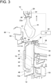
- FIGs. 1 to 3 are each a perspective view showing, in sequence following an operation procedure, a slit forming system 60 incorporating a work measurement device 10, together with the work measurement device 10 according to an embodiment.
- the work measurement device 10 includes a posture holding plate 12 having a posture holding surface 12a for holding a posture of a work W available for work measurement.
- a first work presser 14 is disposed at a position opposite to the posture holding surface 12a across the work W.
- the first work presser 14 includes a drive part 16 for moving the first work presser 14 in a direction getting close to or away from the posture holding surface 12a.
- the first work presser 14 is configured to get close to the posture holding surface 12a by the drive part 16 to be able to press the work W against the posture holding surface 12a.
- the work measurement device 10 further includes a contact 19 disposed to be able to contact the work W, and a moving unit 20 for supporting and moving the work W.
- the moving unit 20 is configured to be able to move, relative to the contact 19, the work W pressed against the posture holding surface 12a, and the contact 19 is configured to be able to contact the work W downstream of the first work presser 14 in a direction where the work W is moved relative to the contact 19.
- downstream means downstream in the direction where the work W is moved relative to the contact 19 by the moving unit 20.
- the contact 19 when the work W is moved relative to the contact 19 by the moving unit 20, the contact 19 can track the surface of the work W while contacting the surface of the work W. Thus, by detecting the trajectory of the contact 19, it is possible to measure the form of the work W. However, if the contact 19 tracks a section where the work W is deformed by a pressing force of the first work presser 14, an error may be caused in a measurement value of the work form. According to the present embodiment, since the contact 19 contacts the work W downstream of the first work presser 14, the contact 19 can track a section other than the section where the work W is deformed by the pressing force of the first work presser 14. Thus, it is possible to measure a true form of the work. Further, since the contact 19 contacts the work W downstream of the first work presser 14, the contact 19 can track a region close to almost the entire length of the work W by movement of the work W. Thus, it is possible to measure the form close to almost the entire length of the work W.
- the contact 19 can measure the form of the work W, and also has a capability to stably hold the work W at a predetermined position by contacting the work W.
- the drive part 16 for driving the first work presser 14 includes an air cylinder 18 with a piston being coupled to a link mechanism 17 of the first work presser 14.
- the link mechanism 17 moves the first work presser 14 in the direction getting close to or away from the posture holding plate 12.
- FIG. 2 does not illustrate the link mechanism 17 and the air cylinder 18.
- the posture holding plate 12 is mounted on a drive part (not shown) via a support part 32.
- the posture holding plate 12 can get close to or away from the work W suspended by a clamper 22 at a measurement position, by the drive part. Thus, it is possible to hold the work W at a desired measurement position.
- the moving unit 20 includes the clamper 22 capable of suspending the work W, and a drive part 24 capable of lifting the clamper 22 along the vertical direction. Since the moving unit 20 includes the clamper 22 to be lifted while suspending the work W, it is possible to downsize the moving unit 20.
- the clamper 22 includes a chuck 26 for opening/closing an opening 22a (see FIG. 6 ) where the work W can be inserted, and a drive part 28 for driving the chuck 26 to open/close the opening 22a of the clamper 22.
- a controller 30 controls the drive part 24 to control a lifted position of the clamper 22, as well as controls the drive part 28 to control an opening/closing timing of the chuck 26.
- the work W is conveyed to the front of the posture holding surface 12a while being suspended by the clamper 22, and stops in front of the posture holding surface 12a. Subsequently, the work W is interposed by the first work presser 14 and the posture holding surface 12a to be held at the measurement position.
- the first work presser 14 is constituted by a plate-like body. Further, since the clamper 22 moves in the vertical direction, the posture holding plate 12 and the first work presser 14 are disposed to extend along the vertical direction as well, and the posture holding plate 12 and the first work presser 14 are each configured to be movable back and forth with respect to the work W while facing the vertical direction by a corresponding one of the drive parts. Thus, the posture holding plate 12 and the first work presser 14 do not interfere with movement of the work W.
- the contact 19 is disposed to contact the work W in the vicinity of a clamp position of the clamper 22.
- the contact 19 can track the work surface over almost the entire length of the work W and can measure the form close to almost the entire length of the work W.
- a second work presser 34 is disposed opposite to the contact 19 downstream of the first work presser 14.
- the second work presser 34 is configured to be able to interpose the work W together with the contact 19.
- the second work presser 34 is mounted on top of the posture holding plate 12 to be rotatable about a shaft 36.
- the second work presser 34 has one end portion coupled to a piston 38a of an air cylinder 38. By expansion and contraction of the piston 38a, the second work presser 34 is movable back and forth with respect to the work W at the measurement position centered on the shaft 36.
- the work W conveyed to the front of the posture holding surface 12a while being suspended by the clamper 22 stops in front of the posture holding surface 12a. Subsequently, forward movement is performed in order of the posture holding plate 12, the second work presser 34, the contact 19, and the first work presser 14 toward the work W, thereby fixing the work W.
- a biasing unit 40 is provided for biasing the contact 19 toward the second work presser 34 in a direction along the posture holding surface 12a.
- a biasing unit 40 is provided for biasing the contact 19 toward the second work presser 34 in a direction along the posture holding surface 12a.
- the biasing unit 40 includes an air cylinder 41 configured to elastically bias the contact 19.
- an air cylinder 41 configured to elastically bias the contact 19.
- the air cylinder 41 is fixed to a surface opposite to the posture holding plate 12 with respect to the posture holding surface 12a. Consequently, the air cylinder 41 moves together with the posture holding plate 12, and thus can be disposed so as not to disturb movement of the work W.
- the contact 19 is composed of a shaft 46 mounted on the posture holding surface 12a of the posture holding plate 12, an arm 48 which is mounted at one end to the shaft 46 and is rotatable about the shaft 46, and a contact bar 50 mounted to a tip portion of the arm 48 opposite to the shaft 46.
- the contact bar 50 extends in a direction crossing the vertical direction (substantially the horizontal direction, in FIG. 1 ), and thus can reliably contact the work W even if the work W suspended by the clamper 22 in the vertical direction is shifted to a certain degree in the horizontal direction.
- a tip portion of the piston of the air cylinder 41 is mounted to one end portion of the arm 44, which is mounted on the shaft 46, via the shaft 42 to be rotatable about the shaft.
- the arm 44 which is mounted on the shaft 46, via the shaft 42 to be rotatable about the shaft.
- the controller 30 before lifting of the clamper 22 is started with the work W being fixed on the posture holding surface 12a, the controller 30 operates the second work presser 34 to retreat from the work W.
- the second work presser 34 can be retreated from the work W before lifting of the clamper 22 is started, the second work presser 34 does not interfere with the lifting work W.
- FIG. 4 shows a control system of the work measurement device 10 according to an embodiment.
- a moving amount detection part 52 capable of detecting a moving amount of the work W by the moving unit 20, and a position detection part 53 for detecting a position of the contact 19 tracking the surface of the work W are provided.
- the controller 30 incorporates a trajectory computation part 54 which is configured to be able to plot the trajectory of the contact 19 on two-dimensional coordinates having detected values by the moving amount detection part 52 and the position detection part 53 as coordinate axes, respectively.
- a trajectory computation part 54 which is configured to be able to plot the trajectory of the contact 19 on two-dimensional coordinates having detected values by the moving amount detection part 52 and the position detection part 53 as coordinate axes, respectively.
- the trajectory computation part 54 is implemented by a processor which is a constituent element of the controller 30.
- the processor is CPU, GPU, MPU, DSP, various kinds of computation devices other than these, or a combination of these.
- the processor may be an integrated circuit of PLD, ASIC, FPGA, MCU, and the like.
- the position detection part 53 is constituted by an encoder. As shown in FIG. 3 , the encoder is disposed on a back surface of the posture holding plate 12, and the shaft 46 is disposed so as to penetrate the posture holding plate 12 and is coupled to the encoder. The encoder detects the position of the contact 19 from a rotation angle of the shaft 46.
- the controller 30 includes a display part 56, and the display part 56 displays the trajectory of the contact 19 represented on the two-dimensional coordinates.
- FIG. 5 shows an example of the trajectory of the contact displayed on the display part 56.
- point A indicates a position of the contact 19 where the work W is interposed so as to contact the posture holding surface 12a by the posture holding plate 12 and the first work presser 14, and before the work W is lifted by the moving unit 20.
- point B indicates a position of the contact 19 of the moment when the work W is lifted and the contact 19 is separated from the work W.
- a length L indicates a length from a position where the contact 19 is in contact before movement of the work W to a lowest end of the work W opposite to the clamp position by the clamper 22. From the length L, it is possible to compute the entire length of the work W.
- the contact 19 is configured to contact the work W downstream of the first work presser 14 in the direction where the work W is moved relative to the contact 19. That is, as shown in FIGs. 1 to 3 , in the embodiment where the work W is lifted by the moving unit 20, since the contact 19 contacts the work W in the vicinity of the position where the work W is suspended by the clamper 22, the length L is close to almost the entire length of the work W. Therefore, it is possible to accurately measure the form close to almost the entire length of the work W by the trajectory of the contact 19.
- the downstream side is a vertically upper side. In another embodiment, the downstream side may be a vertically lower side. In this case, a configuration where the work W is lowered relative to the contact 19 may be adopted in the work measurement device 10.
- the slit forming system 60 includes the work measurement device 10 according to each embodiment described above, and a slit forming blade 62 disposed to be movable back and forth with respect to the work position where the work W is interposed between the posture holding surface 12a and the first work presser 14.
- the slit forming system 60 is applied to, for example, an automatic de-boning device for separating bone-in meat into a meat portion and a bone portion completely from slit formation.
- the clamper 22 suspending the work W sequentially moves to a plurality of processing stations constituting the automatic de-boning device to perform a de-boning process of the work W.
- the slit forming system 60 constitutes the slit forming station of the automatic de-boning device.
- the slit forming system 60 When the work W is conveyed to the slit forming system 60 by the clamper 22 and is positioned in front of the posture holding plate 12, the work W is interposed between the posture holding surface 12a and the first work presser 14. Then, before the work W moves together with the clamper 22, the slit forming blade 62 is inserted into the work W. Subsequently, if the work W moves relative to the contact 19 and the slit forming blade 62, it is possible to simultaneously perform form measurement and slit formation of the work W. Therefore, if the slit forming system 60 is applied to the automatic de-boning device, it is possible to downsize the automatic de-boning device. Further, by measuring the entire length of the individual work W, it is possible to improve yield of the meat portion in a subsequent bone-meat separation step.
- the slit forming blade 62 is supported by the support part 64, and is configured to be able to get close to or away from the work W held at a slit forming position (the same position as the work measurement position) on the posture holding surface 12a.
- the slit forming blade 62 is configured to be insertable into the work W downstream of the first work presser 14 in the direction where the work W is moved relative to the contact 19.
- the slit forming blade 62 is configured to be insertable into the work W downstream of the first work presser 14 in the direction where the work W is moved relative to the contact 19.
- the slit forming blade 62 can be inserted in the vicinity of the position where the work W is interposed by the contact 19 and the second work presser 34.
- slit formation is possible over almost the entire length of the work W.
- the work W is bone-in limb meat.
- FIG. 6 shows bone-in limb meat of poultry as an example.
- Bone-in limb meat Mb includes a bone portion b and a meat portion m attached around the bone portion b.
- the bone-in limb meat Mb includes a knee portion N in an axial center, and a knee joint portion n exists on the inner side of the knee portion N.
- the moving unit 20 includes the clamper 22 capable of suspending the bone-in limb meat Mb, and the drive part 24 for lifting the clamper 22 along the vertical direction. Then, the slit forming blade 62 is configured to be inserted into an ankle portion f.
- the work W interferes with the second work presser 34 if the work W moves relatively, and thus as described above, the second work presser 34 separates from the work W before the work W moves.
- the work W is pressed by the contact 19 alone, the work W is likely to move in an opposite direction to the contact 19.
- the slit forming blade 62 is inserted so as to contact the surface of the bone portion b opposite to the contact 19.
- the biasing force of the contact 19 acting on the work W is received by supporting bone portion b with the slit forming blade 62 instead of the second work presser 34, making it possible to suppress a horizontal variation in the work W at the time of slit formation.
- By relatively moving the work W in the direction of the arrow a in this state it is possible to accurately form a cut c between the bone portion b and the meat portion m.
- the controller 30 decreases the biasing force of the contact 19 with respect to the work W relative to before the lifting.
- the controller 30 decreases the biasing force of the contact 19 with respect to the work W relative to before the lifting.
- the bone-in limb meat Mb is bone-in limb meat of poultry
- one surface of the bone-in limb meat Mb is a skin surface covered with skin
- the other surface is a meat surface which has no skin and is exposed.
- a meat surface s1 is fixed on the posture holding surface 12a to face the side of the slit forming blade 62 and in the slit forming step, the slit forming blade 62 is inserted into the meat surface s1.
- the skin surface is not bruised, making it possible to increase a value as boneless meat.
- the contact since the contact contacts the work downstream of the first work presser in the relative movement direction of the work by the moving unit, the contact can track a section other than a section where the work is deformed by a pressing force of the first work presser. Thus, it is possible to measure a true form of the work. Further, since the contact contacts the work downstream of the first work presser in the relative movement direction of the work by the moving unit, the contact can track a region close to almost the entire length of the work by movement of the work. Thus, it is possible to measure a work form close to almost the entire length of the work.
- the work measurement device (10) is the work measurement device defined in 1) which includes a second work presser (34) for interposing the work (W) together with the contact (19), the second work presser (34) being disposed opposite to the contact (19) downstream of the first work presser (14) in the relative movement direction.
- the work measurement device (10) is the work measurement device defined in 2) which includes a controller (30) for retreating the second work presser (34) from the work (W) before movement of the work (W) by the moving unit (20) is started.
- the second work presser since the second work presser can be retreated from the work before movement of the work by the moving unit is started, the second work presser does not interfere with the lifting work. Thus, it is possible to smoothly lift the work.
- the work measurement device (10) is the work measurement device defined in 2) or 3) which includes a biasing unit (40) for biasing the contact (19) toward the second work presser (34) in a direction along the posture holding surface (12a).
- the work measurement device is the work measurement device defined in 4), where the biasing unit (40) includes an air cylinder (41) configured to elastically bias the contact (19).
- the biasing unit includes the air cylinder, and thus can be downsized, and by regulating an air pressure of the air cylinder, it is possible to adjust the biasing force of the contact with respect to the work.
- the work measurement device (10) is the work measurement device defined in any one of 1) to 5), where the moving unit (20) includes a clamper (22) capable of suspending the work (W), and a drive part (24) for lifting the clamper (22) along a vertical direction.
- the moving unit includes the clamper capable of suspending the work, and thus can be downsized.
- the work measurement device is applied to an automatic de-boning device, it is possible to perform a de-boning process by transferring the clamper suspending the work directly to another processing station, making it possible to continuously perform a plurality of processing steps while the work is suspended by the clamper.
- the work measurement device (10) is the work measurement device defined in any one of 1) to 6) which includes a moving amount detection part (52) capable of detecting a moving amount of the work (W) by the moving unit (20), a position detection part (53) for detecting a position of the contact (19), and a trajectory computation part (54) capable of plotting a trajectory of the contact (19) on two-dimensional coordinates having detected values by the moving amount detection part (52) and the position detection part (53) as coordinate axes, respectively.
- a moving amount detection part (52) capable of detecting a moving amount of the work (W) by the moving unit (20)
- a position detection part (53) for detecting a position of the contact (19)
- a trajectory computation part (54) capable of plotting a trajectory of the contact (19) on two-dimensional coordinates having detected values by the moving amount detection part (52) and the position detection part (53) as coordinate axes, respectively.
- a slit forming system (60) includes the above-described work measurement device, and a slit forming blade (62) disposed to be movable back and forth with respect to a work position where the work (W) is interposed by the posture holding surface (12a) and the first work presser (14).
- the slit forming system (60) is the slit forming system defined in 8), where the work (W) is bone-in limb meat (Mb), the moving unit (20) includes a clamper (22) capable of suspending the bone-in limb meat (Mb), and a drive part (24) for lifting the clamper (22) along a vertical direction, the bone-in limb meat (Mb) is clamped at an ankle portion (f) thereof by the clamper (22), and the slit forming blade (62) is configured to be inserted into the ankle portion (f).
- the work (W) is bone-in limb meat (Mb)
- the moving unit (20) includes a clamper (22) capable of suspending the bone-in limb meat (Mb), and a drive part (24) for lifting the clamper (22) along a vertical direction
- the bone-in limb meat (Mb) is clamped at an ankle portion (f) thereof by the clamper (22)
- the slit forming blade (62) is configured to be inserted
Landscapes
- Engineering & Computer Science (AREA)
- Life Sciences & Earth Sciences (AREA)
- Food Science & Technology (AREA)
- Wood Science & Technology (AREA)
- Zoology (AREA)
- Mechanical Engineering (AREA)
- Forests & Forestry (AREA)
- A Measuring Device Byusing Mechanical Method (AREA)
- Machine Tool Sensing Apparatuses (AREA)
- Processing Of Meat And Fish (AREA)
- Multi-Process Working Machines And Systems (AREA)
- Investigating Strength Of Materials By Application Of Mechanical Stress (AREA)
Abstract
Description
- The present disclosure relates to a work measurement device and a slit forming system.
- Slaughter work of a livestock carcass for meat is hard labor and is also inefficient if done manually, and thus has been automated. The present applicant has developed an automation technology in this field for a long time.
Patent Document 1 proposes an automatic de-boning technique for bone-in meat in the middle of slaughtering, and Patent Document 2 proposes an automatic measurement technique of measuring the entire length of bone-in meat during conveyance. Further, Patent Document 3 proposes an automatic slit forming technique of forming a slit in bone-in meat during conveyance, and Patent Document 4 proposes an automatic de-boning technique increased in processing efficiency. -
- Patent Document 1:
JP3483710B - Patent Document 2:
WO2019/131357A - Patent Document 3:
WO2019/131362A - Patent Document 4:
WO2019/131363A - As demand for meat increases, an automatic slaughter technique of a livestock carcass for meat is required of, for example, improvement in de-boning efficiency (such as an increase in number of processes per unit time) when bone-in meat obtained by slaughtering the livestock carcass for meat is further separated into a bone portion and a meat portion, a downsized automation device, versatility, and further improvement in yield of meat portions. In order to improve the yield of the meat portions, it is necessary, during the de-boning step, to measure the size of an individual work and to perform, based on the measurement value, a tailored de-boning process for each work. In Patent Document 2, when the entire length of the individual bone-in meat is measured, a measuring first pressing plate is held against the work to detect a trajectory of the first pressing plate, thereby measuring a form including the entire length of the bone-in meat. However, the first pressing plate contacts the work in the vicinity of a position where a second pressing plate for pressing the work presses the work, resulting in the first pressing plate tracking the surface of the work deformed by a pressing force of the second pressing plate. Thus, it may be impossible to accurately measure a true form of the work before being deformed.
- The present disclosure was made in view of the above, and an object of the present disclosure is to be able to accurately measure a form including the size, the shape, the entire length and the like of bone-in meat (may simply be referred to as a "form", hereinafter) in, for example, an automatic de-boning step for the bone-in meat.
- In order to achieve the above object, a work measurement device according to the present disclosure includes a posture holding surface for holding a posture of a work, a first work presser capable of pressing the work against the posture holding surface from an opposite side to the posture holding surface across the work, a contact disposed to be able to contact the work, a moving unit for moving, relative to the contact, the work pressed against the posture holding surface by the first work presser. The contact is configured to contact the work downstream of the first work presser in a relative movement direction of the work by the moving unit.
- In the present specification, "work" refers to bone-in meat obtained by slaughtering a livestock carcass for meat (the meat in a stage before being completely separated into a bone portion and a meat portion; for example, bone-in limb meat such as arm meat or thigh meat).
- A slit forming system according to the present disclosure includes the above-described work measurement device, and a slit forming blade disposed to be movable back and forth with respect to a work position where the work is interposed by the posture holding surface and the first work presser.
- A work measurement device according to the present disclosure can accurately measure the form of individual work, and thus, for example, when applied to an automatic de-boning device, it is possible to improve yield of a meat portion separated from a bone portion of individual work. Further, the slit forming system according to the present disclosure can simultaneously perform form measurement and slit formation of individual work, and thus, for example, when applied to the automatic de-boning device, it is possible to improve processing efficiency, to downsize the automatic de-boning device, as well as to measure the entire length of the individual work, making it possible to improve yield of the meat portion in a subsequent bone-meat separation step.
-
-
FIG. 1 is a perspective view of a work measurement device and a slit forming device according to an embodiment. -
FIG. 2 is a perspective view of the work measurement device and the slit forming device according to an embodiment. -
FIG. 3 is a perspective view of the work measurement device and the slit forming device according to an embodiment. -
FIG. 4 is a block diagram showing a control system of the work measurement device and the slit forming device according to an embodiment. -
FIG. 5 is a chart representing a trajectory of a contact on two-dimensional coordinates according to an embodiment. -
FIG. 6 is a schematic view of bone-in limb meat suspended by a clamper. - Some embodiments of the present invention will be described below with reference to the accompanying drawings. It is intended, however, that unless particularly specified, dimensions, materials, shapes, relative positions and the like of components described or shown in the drawings as the embodiments shall be interpreted as illustrative only and not intended to limit the scope of the present invention.
- For instance, an expression of relative or absolute arrangement such as "in a direction", "along a direction", "parallel", "orthogonal", "centered", "concentric" and "coaxial" shall not be construed as indicating only the arrangement in a strict literal sense, but also includes a state where the arrangement is relatively displaced by a tolerance, or by an angle or a distance whereby it is possible to achieve the same function.
- For instance, an expression of an equal state such as "same", "equal", and "uniform" shall not be construed as indicating only the state in which the feature is strictly equal, but also includes a state in which there is a tolerance or a difference that can still achieve the same function.
- Further, for instance, an expression of a shape such as a rectangular shape or a tubular shape shall not be construed as only the geometrically strict shape, but also includes a shape with unevenness or chamfered corners within the range in which the same effect can be achieved.
- On the other hand, an expressions such as "comprising", "including", "having", "containing", and "constituting" one constitutional element are not intended to be exclusive of other constitutional elements.
-
FIGs. 1 to 3 are each a perspective view showing, in sequence following an operation procedure, aslit forming system 60 incorporating awork measurement device 10, together with thework measurement device 10 according to an embodiment. As shown inFIG. 1 , thework measurement device 10 includes aposture holding plate 12 having aposture holding surface 12a for holding a posture of a work W available for work measurement. Afirst work presser 14 is disposed at a position opposite to theposture holding surface 12a across the work W. Thefirst work presser 14 includes adrive part 16 for moving the first work presser 14 in a direction getting close to or away from theposture holding surface 12a. Thefirst work presser 14 is configured to get close to theposture holding surface 12a by thedrive part 16 to be able to press the work W against theposture holding surface 12a. - The
work measurement device 10 further includes acontact 19 disposed to be able to contact the work W, and a movingunit 20 for supporting and moving the work W. The movingunit 20 is configured to be able to move, relative to thecontact 19, the work W pressed against theposture holding surface 12a, and thecontact 19 is configured to be able to contact the work W downstream of the first work presser 14 in a direction where the work W is moved relative to thecontact 19. - In the present specification, "downstream" means downstream in the direction where the work W is moved relative to the
contact 19 by the movingunit 20. - In the above configuration, when the work W is moved relative to the
contact 19 by the movingunit 20, thecontact 19 can track the surface of the work W while contacting the surface of the work W. Thus, by detecting the trajectory of thecontact 19, it is possible to measure the form of the work W. However, if thecontact 19 tracks a section where the work W is deformed by a pressing force of the first work presser 14, an error may be caused in a measurement value of the work form. According to the present embodiment, since thecontact 19 contacts the work W downstream of the first work presser 14, thecontact 19 can track a section other than the section where the work W is deformed by the pressing force of the first work presser 14. Thus, it is possible to measure a true form of the work. Further, since thecontact 19 contacts the work W downstream of the first work presser 14, thecontact 19 can track a region close to almost the entire length of the work W by movement of the work W. Thus, it is possible to measure the form close to almost the entire length of the work W. - As described above, the
contact 19 can measure the form of the work W, and also has a capability to stably hold the work W at a predetermined position by contacting the work W. - In an embodiment, as shown in
FIG. 1 , thedrive part 16 for driving thefirst work presser 14 includes anair cylinder 18 with a piston being coupled to alink mechanism 17 of thefirst work presser 14. By reciprocation of the piston, thelink mechanism 17 moves the first work presser 14 in the direction getting close to or away from theposture holding plate 12.FIG. 2 does not illustrate thelink mechanism 17 and theair cylinder 18. - In an embodiment, as shown in
FIG. 1 , theposture holding plate 12 is mounted on a drive part (not shown) via asupport part 32. Theposture holding plate 12 can get close to or away from the work W suspended by aclamper 22 at a measurement position, by the drive part. Thus, it is possible to hold the work W at a desired measurement position. - As shown in
FIG. 2 , the movingunit 20 includes theclamper 22 capable of suspending the work W, and adrive part 24 capable of lifting theclamper 22 along the vertical direction. Since the movingunit 20 includes theclamper 22 to be lifted while suspending the work W, it is possible to downsize the movingunit 20. - In an embodiment, the
clamper 22 includes achuck 26 for opening/closing an opening 22a (seeFIG. 6 ) where the work W can be inserted, and adrive part 28 for driving thechuck 26 to open/close the opening 22a of theclamper 22. Acontroller 30 controls thedrive part 24 to control a lifted position of theclamper 22, as well as controls thedrive part 28 to control an opening/closing timing of thechuck 26. The work W is conveyed to the front of theposture holding surface 12a while being suspended by theclamper 22, and stops in front of theposture holding surface 12a. Subsequently, the work W is interposed by thefirst work presser 14 and theposture holding surface 12a to be held at the measurement position. - In an embodiment, the
first work presser 14 is constituted by a plate-like body. Further, since theclamper 22 moves in the vertical direction, theposture holding plate 12 and thefirst work presser 14 are disposed to extend along the vertical direction as well, and theposture holding plate 12 and thefirst work presser 14 are each configured to be movable back and forth with respect to the work W while facing the vertical direction by a corresponding one of the drive parts. Thus, theposture holding plate 12 and thefirst work presser 14 do not interfere with movement of the work W. - In an embodiment, the
contact 19 is disposed to contact the work W in the vicinity of a clamp position of theclamper 22. Thus, thecontact 19 can track the work surface over almost the entire length of the work W and can measure the form close to almost the entire length of the work W. - In an embodiment, if the moving
unit 20 moves the work W relative to thecontact 19, asecond work presser 34 is disposed opposite to thecontact 19 downstream of thefirst work presser 14. Thesecond work presser 34 is configured to be able to interpose the work W together with thecontact 19. By further interposing the work W, which is interposed by theposture holding plate 12 and thefirst work presser 14, by thecontact 19 and thesecond work presser 34, it is possible to accurately and stably place the work W at a desired position. Thus, it is possible to smoothly measure the form of the work W. - In an embodiment, as shown in
FIG. 1 , thesecond work presser 34 is mounted on top of theposture holding plate 12 to be rotatable about ashaft 36. Thesecond work presser 34 has one end portion coupled to apiston 38a of anair cylinder 38. By expansion and contraction of thepiston 38a, thesecond work presser 34 is movable back and forth with respect to the work W at the measurement position centered on theshaft 36. - In an embodiment, the work W conveyed to the front of the
posture holding surface 12a while being suspended by theclamper 22 stops in front of theposture holding surface 12a. Subsequently, forward movement is performed in order of theposture holding plate 12, thesecond work presser 34, thecontact 19, and thefirst work presser 14 toward the work W, thereby fixing the work W. - In an embodiment, as shown in
FIG. 3 , a biasingunit 40 is provided for biasing thecontact 19 toward thesecond work presser 34 in a direction along theposture holding surface 12a. Thus, it is possible to cause thecontact 19 to track the surface of the work W with a biasing force. Thus, even if the surface shape of the work W changes, it is possible to always cause thecontact 19 to follow the surface of the work W. Thus, it is possible to accurately measure the surface shape of the work. - Further, in the above embodiment, since the
contact 19 is biased in the direction along theposture holding surface 12a by the biasingunit 40, a pressing force with respect to the work W by thecontact 19 and thesecond work presser 34, and a pressing force with respect to the work W by theposture holding plate 12 and thefirst work presser 14 act in a direction orthogonal to each other. Thus, it is possible to place the work W at the predetermined position more accurately and stably. - In an embodiment, as shown in
FIG. 3 , the biasingunit 40 includes anair cylinder 41 configured to elastically bias thecontact 19. Thus, it is possible to downsize the biasingunit 40, as well as to adjust the biasing force applied to the work W by thecontact 19 by regulating an air pressure inside theair cylinder 41. - In an embodiment, the
air cylinder 41 is fixed to a surface opposite to theposture holding plate 12 with respect to theposture holding surface 12a. Consequently, theair cylinder 41 moves together with theposture holding plate 12, and thus can be disposed so as not to disturb movement of the work W. - In an embodiment, as shown in
FIG. 3 , thecontact 19 is composed of ashaft 46 mounted on theposture holding surface 12a of theposture holding plate 12, anarm 48 which is mounted at one end to theshaft 46 and is rotatable about theshaft 46, and acontact bar 50 mounted to a tip portion of thearm 48 opposite to theshaft 46. Thecontact bar 50 extends in a direction crossing the vertical direction (substantially the horizontal direction, inFIG. 1 ), and thus can reliably contact the work W even if the work W suspended by theclamper 22 in the vertical direction is shifted to a certain degree in the horizontal direction. - Further, in an embodiment, a tip portion of the piston of the
air cylinder 41 is mounted to one end portion of thearm 44, which is mounted on theshaft 46, via theshaft 42 to be rotatable about the shaft. Thus, by expansion and contraction of the piston, it is possible to rotate thearm 48 around theshaft 46. - In an embodiment, as shown in
FIG. 2 , before lifting of theclamper 22 is started with the work W being fixed on theposture holding surface 12a, thecontroller 30 operates thesecond work presser 34 to retreat from the work W. Thus, thesecond work presser 34 can be retreated from the work W before lifting of theclamper 22 is started, thesecond work presser 34 does not interfere with the lifting work W. Thus, it is possible to smoothly lift the work W. -
FIG. 4 shows a control system of thework measurement device 10 according to an embodiment. As shown inFIG. 4 , a movingamount detection part 52 capable of detecting a moving amount of the work W by the movingunit 20, and aposition detection part 53 for detecting a position of thecontact 19 tracking the surface of the work W are provided. Further, thecontroller 30 incorporates atrajectory computation part 54 which is configured to be able to plot the trajectory of thecontact 19 on two-dimensional coordinates having detected values by the movingamount detection part 52 and theposition detection part 53 as coordinate axes, respectively. Thus, it is possible to accurately grasp the form of the work W from the trajectory of thecontact 19 displayed on the two-dimensional coordinates. - The
trajectory computation part 54 according to an embodiment is implemented by a processor which is a constituent element of thecontroller 30. The processor is CPU, GPU, MPU, DSP, various kinds of computation devices other than these, or a combination of these. The processor may be an integrated circuit of PLD, ASIC, FPGA, MCU, and the like. - In an embodiment, the
position detection part 53 is constituted by an encoder. As shown inFIG. 3 , the encoder is disposed on a back surface of theposture holding plate 12, and theshaft 46 is disposed so as to penetrate theposture holding plate 12 and is coupled to the encoder. The encoder detects the position of thecontact 19 from a rotation angle of theshaft 46. - In an embodiment, as shown in
FIG. 4 , thecontroller 30 includes adisplay part 56, and thedisplay part 56 displays the trajectory of thecontact 19 represented on the two-dimensional coordinates.FIG. 5 shows an example of the trajectory of the contact displayed on thedisplay part 56. In the chart, point A indicates a position of thecontact 19 where the work W is interposed so as to contact theposture holding surface 12a by theposture holding plate 12 and thefirst work presser 14, and before the work W is lifted by the movingunit 20. Further, point B indicates a position of thecontact 19 of the moment when the work W is lifted and thecontact 19 is separated from the work W. A length L indicates a length from a position where thecontact 19 is in contact before movement of the work W to a lowest end of the work W opposite to the clamp position by theclamper 22. From the length L, it is possible to compute the entire length of the work W. - In the above embodiment, the
contact 19 is configured to contact the work W downstream of thefirst work presser 14 in the direction where the work W is moved relative to thecontact 19. That is, as shown inFIGs. 1 to 3 , in the embodiment where the work W is lifted by the movingunit 20, since thecontact 19 contacts the work W in the vicinity of the position where the work W is suspended by theclamper 22, the length L is close to almost the entire length of the work W. Therefore, it is possible to accurately measure the form close to almost the entire length of the work W by the trajectory of thecontact 19. - In the exemplary embodiment shown in
FIGs. 1 to 3 , the downstream side is a vertically upper side. In another embodiment, the downstream side may be a vertically lower side. In this case, a configuration where the work W is lowered relative to thecontact 19 may be adopted in thework measurement device 10. - The
slit forming system 60 according to an embodiment includes thework measurement device 10 according to each embodiment described above, and aslit forming blade 62 disposed to be movable back and forth with respect to the work position where the work W is interposed between theposture holding surface 12a and thefirst work presser 14. Theslit forming system 60 is applied to, for example, an automatic de-boning device for separating bone-in meat into a meat portion and a bone portion completely from slit formation. In this case, theclamper 22 suspending the work W sequentially moves to a plurality of processing stations constituting the automatic de-boning device to perform a de-boning process of the work W. Theslit forming system 60 constitutes the slit forming station of the automatic de-boning device. - When the work W is conveyed to the
slit forming system 60 by theclamper 22 and is positioned in front of theposture holding plate 12, the work W is interposed between theposture holding surface 12a and thefirst work presser 14. Then, before the work W moves together with theclamper 22, theslit forming blade 62 is inserted into the work W. Subsequently, if the work W moves relative to thecontact 19 and theslit forming blade 62, it is possible to simultaneously perform form measurement and slit formation of the work W. Therefore, if theslit forming system 60 is applied to the automatic de-boning device, it is possible to downsize the automatic de-boning device. Further, by measuring the entire length of the individual work W, it is possible to improve yield of the meat portion in a subsequent bone-meat separation step. - In an embodiment, the
slit forming blade 62 is supported by thesupport part 64, and is configured to be able to get close to or away from the work W held at a slit forming position (the same position as the work measurement position) on theposture holding surface 12a. - In an embodiment, the
slit forming blade 62 is configured to be insertable into the work W downstream of thefirst work presser 14 in the direction where the work W is moved relative to thecontact 19. Thus, it is possible to perform slit formation in almost the entire length of the work from the vicinity of theclamper 22 to the lowest portion. - In the embodiments shown in
FIGs. 1 to 3 , theslit forming blade 62 can be inserted in the vicinity of the position where the work W is interposed by thecontact 19 and thesecond work presser 34. Thus, slit formation is possible over almost the entire length of the work W. - In an embodiment, the work W is bone-in limb meat.
FIG. 6 shows bone-in limb meat of poultry as an example. Bone-in limb meat Mb includes a bone portion b and a meat portion m attached around the bone portion b. The bone-in limb meat Mb includes a knee portion N in an axial center, and a knee joint portion n exists on the inner side of the knee portion N. The movingunit 20 includes theclamper 22 capable of suspending the bone-in limb meat Mb, and thedrive part 24 for lifting theclamper 22 along the vertical direction. Then, theslit forming blade 62 is configured to be inserted into an ankle portion f. In the process of inserting the ankle portion f into theopening 22a of theclamper 22 to be suspended and lifting the ankle portion f in the direction of an arrow a, form measurement and slit formation of the work W are performed simultaneously. Since theslit forming blade 62 is inserted into the ankle portion f, it is possible to form a slit over the entire length of the bone-in limb meat Mb. Therefore, if the present disclosure is applied to the automatic de-boning device, it is possible to downsize the automatic de-boning device, as well as to improve yield of the meat portion in the subsequent bone-meat separation step by measuring the entire length of the individual work W. - In an embodiment, the work W interferes with the
second work presser 34 if the work W moves relatively, and thus as described above, thesecond work presser 34 separates from the work W before the work W moves. In this case, the work W is pressed by thecontact 19 alone, the work W is likely to move in an opposite direction to thecontact 19. In order to suppress such movement of the work W, in an embodiment, as shown inFIG. 6 , theslit forming blade 62 is inserted so as to contact the surface of the bone portion b opposite to thecontact 19. Thus, the biasing force of thecontact 19 acting on the work W is received by supporting bone portion b with theslit forming blade 62 instead of thesecond work presser 34, making it possible to suppress a horizontal variation in the work W at the time of slit formation. By relatively moving the work W in the direction of the arrow a in this state, it is possible to accurately form a cut c between the bone portion b and the meat portion m. - In an embodiment, when the work W is lifted together with the
clamper 22, thecontroller 30 decreases the biasing force of thecontact 19 with respect to the work W relative to before the lifting. Thus, it is possible to press the work W against theslit forming blade 62 with an appropriate force, allowing for slit formation along the bone portion b. - If the bone-in limb meat Mb is bone-in limb meat of poultry, one surface of the bone-in limb meat Mb is a skin surface covered with skin, and the other surface is a meat surface which has no skin and is exposed. In an embodiment, as shown in
FIGs. 1 to 3 , a meat surface s1 is fixed on theposture holding surface 12a to face the side of theslit forming blade 62 and in the slit forming step, theslit forming blade 62 is inserted into the meat surface s1. Thus, the skin surface is not bruised, making it possible to increase a value as boneless meat. - The contents described in the above embodiments would be understood as follows, for instance.
- 1) A work measurement device (10) according to an aspect includes a posture holding surface (12a) for holding a posture of a work (W), a first work presser (14) capable of pressing the work against the posture holding surface (12a) from an opposite side to the posture holding surface (12a) across the work (W), a contact (19) disposed to be able to contact the work, a moving unit (20) for moving, relative to the contact (19), the work (W) pressed against the posture holding surface (12a) by the first work presser (14). The contact (19) is configured to contact the work (W) downstream of the first work presser (14) in a relative movement direction of the work (W) by the moving unit (20).
- With the above configuration, since the contact contacts the work downstream of the first work presser in the relative movement direction of the work by the moving unit, the contact can track a section other than a section where the work is deformed by a pressing force of the first work presser. Thus, it is possible to measure a true form of the work. Further, since the contact contacts the work downstream of the first work presser in the relative movement direction of the work by the moving unit, the contact can track a region close to almost the entire length of the work by movement of the work. Thus, it is possible to measure a work form close to almost the entire length of the work.
- 2) The work measurement device (10) according to another aspect is the work measurement device defined in 1) which includes a second work presser (34) for interposing the work (W) together with the contact (19), the second work presser (34) being disposed opposite to the contact (19) downstream of the first work presser (14) in the relative movement direction.
- With the above configuration, since the work is interposed from both sides by the contact and the second work presser downstream of the first work presser, it is possible to support the work in the vicinity of a support position of the moving unit. Thus, it is possible to stably hold the work at a predetermined position.
- 3) The work measurement device (10) according to still another aspect is the work measurement device defined in 2) which includes a controller (30) for retreating the second work presser (34) from the work (W) before movement of the work (W) by the moving unit (20) is started.
- With the above configuration, since the second work presser can be retreated from the work before movement of the work by the moving unit is started, the second work presser does not interfere with the lifting work. Thus, it is possible to smoothly lift the work.
- 4) The work measurement device (10) according to yet another aspect is the work measurement device defined in 2) or 3) which includes a biasing unit (40) for biasing the contact (19) toward the second work presser (34) in a direction along the posture holding surface (12a).
- With the above configuration, it is possible to cause the contact to track the surface of the work by the biasing force. Thus, even if a surface shape of the work changes, it is possible to always cause the contact to follow the surface of the work. Thus, it is possible to accurately measure the surface shape of the work.
- 5) The work measurement device according to yet another aspect is the work measurement device defined in 4), where the biasing unit (40) includes an air cylinder (41) configured to elastically bias the contact (19).
- With the above configuration, the biasing unit includes the air cylinder, and thus can be downsized, and by regulating an air pressure of the air cylinder, it is possible to adjust the biasing force of the contact with respect to the work.
- 6) The work measurement device (10) according to yet another aspect is the work measurement device defined in any one of 1) to 5), where the moving unit (20) includes a clamper (22) capable of suspending the work (W), and a drive part (24) for lifting the clamper (22) along a vertical direction.
- With the above configuration, the moving unit includes the clamper capable of suspending the work, and thus can be downsized. In addition, if the work measurement device is applied to an automatic de-boning device, it is possible to perform a de-boning process by transferring the clamper suspending the work directly to another processing station, making it possible to continuously perform a plurality of processing steps while the work is suspended by the clamper.
- 7) The work measurement device (10) according to yet another aspect is the work measurement device defined in any one of 1) to 6) which includes a moving amount detection part (52) capable of detecting a moving amount of the work (W) by the moving unit (20), a position detection part (53) for detecting a position of the contact (19), and a trajectory computation part (54) capable of plotting a trajectory of the contact (19) on two-dimensional coordinates having detected values by the moving amount detection part (52) and the position detection part (53) as coordinate axes, respectively.
- With the above configuration, it is possible to represent the trajectory of the contact on the two-dimensional coordinates, making it possible to accurately grasp the surface shape of the work. Thus, it is possible to accurately grasp the form of the work.
- 8) A slit forming system (60) according to an aspect includes the above-described work measurement device, and a slit forming blade (62) disposed to be movable back and forth with respect to a work position where the work (W) is interposed by the posture holding surface (12a) and the first work presser (14).
- With the above configuration, moving the work relative to the contact and the slit forming blade by the moving unit with the above-described slit forming blade being inserted into the work, it is possible to perform slit formation of the work simultaneously with form measurement of the work. Therefore, if the present disclosure is applied to the automatic de-boning device, it is possible to downsize the automatic de-boning device, as well as to improve yield of a meat portion in a subsequent bone-meat separation step by measuring the entire length of the individual work.
- 9) The slit forming system (60) according another aspect is the slit forming system defined in 8), where the work (W) is bone-in limb meat (Mb), the moving unit (20) includes a clamper (22) capable of suspending the bone-in limb meat (Mb), and a drive part (24) for lifting the clamper (22) along a vertical direction, the bone-in limb meat (Mb) is clamped at an ankle portion (f) thereof by the clamper (22), and the slit forming blade (62) is configured to be inserted into the ankle portion (f).
- With the above configuration, since the work is lifted with the slit forming blade being inserted into the ankle portion, it is possible to form a slit in the bone-in limb meat over almost the entire length thereof.
-
- 10
- Work measurement device
- 12
- Posture holding plate
- 12a
- Posture holding surface
- 14
- First work presser
- 16,24,28
- Drive part
- 17
- Link mechanism
- 18, 38, 41
- Air cylinder
- 38a
- Piston
- 19
- Contact
- 20
- Moving unit
- 22
- Clamper
- 22a
- Opening
- 26
- Chuck
- 30
- Controller
- 32, 64
- Support part
- 34
- Second work presser
- 36, 42, 46
- Shaft
- 40
- Biasing unit
- 44,48
- Arm
- 50
- Contact bar
- 52
- Moving amount detection part
- 53
- Position detection part
- 54
- Trajectory computation part
- 60
- Slit forming system
- 62
- Slit forming blade
- Mb
- Bone-in limb meat
- N
- Knee portion
- W
- Work
- b
- Bone portion
- f
- Ankle portion
- m
- Meat portion
- n
- Knee joint portion
Claims (9)
- A work measurement device, comprising:a posture holding surface for holding a posture of a work;a first work presser capable of pressing the work against the posture holding surface from an opposite side to the posture holding surface across the work;a contact disposed to be able to contact the work; anda moving unit for moving, relative to the contact, the work pressed against the posture holding surface by the first work presser,wherein the contact is configured to contact the work downstream of the first work presser in a relative movement direction of the work by the moving unit.
- The work measurement device according to claim 1,
comprising a second work presser for interposing the work together with the contact, the second work presser being disposed opposite to the contact downstream of the first work presser in the relative movement direction. - The work measurement device according to claim 2,
comprising a controller for retreating the second work presser from the work before movement of the work by the moving unit is started. - The work measurement device according to claim 2 or 3,
comprising a biasing unit for biasing the contact toward the second work presser in a direction along the posture holding surface. - The work measurement device according to claim 4,
wherein the biasing unit includes an air cylinder configured to elastically bias the contact. - The work measurement device according to any one of claims 1 to 5,
wherein the moving unit includes:a clamper capable of suspending the work; anda drive part for lifting the clamper along a vertical direction. - The work measurement device according to any one of claims 1 to 6, comprising:a moving amount detection part capable of detecting a moving amount of the work by the moving unit;a position detection part for detecting a position of the contact; anda trajectory computation part capable of plotting a trajectory of the contact on two-dimensional coordinates having detected values by the moving amount detection part and the position detection part as coordinate axes, respectively.
- A slit forming system, comprising:the work measurement device according to any one of claims 1 to 7; anda slit forming blade disposed to be movable back and forth with respect to a work position where the work is interposed by the posture holding surface and the first work presser.
- The slit forming system according to claim 8,wherein the work is bone-in limb meat,wherein the moving unit includes:a clamper capable of suspending the bone-in limb meat; anda drive part for lifting the clamper along a vertical direction,wherein the bone-in limb meat is clamped at an ankle portion thereof by the clamper, andwherein the slit forming blade is configured to be inserted into the ankle portion.
Applications Claiming Priority (2)
| Application Number | Priority Date | Filing Date | Title |
|---|---|---|---|
| JP2020083685A JP7526031B2 (en) | 2020-05-12 | 2020-05-12 | Workpiece measuring device and creasing system |
| PCT/JP2021/016795 WO2021230072A1 (en) | 2020-05-12 | 2021-04-27 | Workpiece measuring device and slitting system |
Publications (4)
| Publication Number | Publication Date |
|---|---|
| EP3964074A1 true EP3964074A1 (en) | 2022-03-09 |
| EP3964074A4 EP3964074A4 (en) | 2022-08-10 |
| EP3964074C0 EP3964074C0 (en) | 2023-09-13 |
| EP3964074B1 EP3964074B1 (en) | 2023-09-13 |
Family
ID=78509688
Family Applications (1)
| Application Number | Title | Priority Date | Filing Date |
|---|---|---|---|
| EP21805079.7A Active EP3964074B1 (en) | 2020-05-12 | 2021-04-27 | Workpiece measuring device and slitting system |
Country Status (10)
| Country | Link |
|---|---|
| US (1) | US12102096B2 (en) |
| EP (1) | EP3964074B1 (en) |
| JP (1) | JP7526031B2 (en) |
| KR (1) | KR102746118B1 (en) |
| AU (1) | AU2021272789B2 (en) |
| BR (1) | BR112022019813A2 (en) |
| ES (1) | ES2960418T3 (en) |
| PL (1) | PL3964074T3 (en) |
| TW (1) | TWI789751B (en) |
| WO (1) | WO2021230072A1 (en) |
Families Citing this family (5)
| Publication number | Priority date | Publication date | Assignee | Title |
|---|---|---|---|---|
| JP7643993B2 (en) | 2021-12-20 | 2025-03-11 | 株式会社前川製作所 | Poultry thigh meat crease inserting device and poultry thigh meat automatic crease inserting method |
| JP7734639B2 (en) * | 2022-09-21 | 2025-09-05 | 株式会社前川製作所 | Bone-in meat clamping device, bone-in meat scoring device, and bone-in meat scoring method |
| JP7720489B2 (en) * | 2022-09-21 | 2025-08-07 | 株式会社前川製作所 | Bone-in meat clamping device |
| JP7701902B2 (en) * | 2022-10-13 | 2025-07-02 | 株式会社前川製作所 | Thigh meat peeling device and thigh meat peeling method |
| JP2024094481A (en) * | 2022-12-28 | 2024-07-10 | 株式会社前川製作所 | Meat processing equipment and meat processing system |
Family Cites Families (27)
| Publication number | Priority date | Publication date | Assignee | Title |
|---|---|---|---|---|
| US5001812A (en) * | 1988-10-31 | 1991-03-26 | Hazenbroek Jacobus E | Revolving poultry thigh deboner |
| JP3483710B2 (en) | 1996-06-21 | 2004-01-06 | 株式会社前川製作所 | Thigh meat auto loading system |
| JP3603981B2 (en) * | 1997-08-18 | 2004-12-22 | 食肉生産技術研究組合 | Pig thigh removal machine and pig thigh removal method |
| NL1012703C2 (en) | 1999-04-06 | 2000-10-09 | Stork Pmt | Method and device for processing a poultry leg. |
| JP4073133B2 (en) | 1999-11-25 | 2008-04-09 | 株式会社前川製作所 | Automatic creasing method and apparatus for deboning chicken thigh meat |
| WO2004068953A1 (en) * | 2003-02-03 | 2004-08-19 | Mayekawa Mfg.Co., Ltd. | Boning system of meat |
| NL1030388C2 (en) * | 2005-11-10 | 2007-05-16 | Systemate Group Bv | Boner. |
| JP4804987B2 (en) * | 2006-03-31 | 2011-11-02 | 国立大学法人岩手大学 | Method for collecting useful part of fish head and device for collecting useful part of fish head |
| WO2009139031A1 (en) * | 2008-05-12 | 2009-11-19 | 株式会社前川製作所 | Loading method and loading device of meat with bone and loading operation program |
| JP5331244B2 (en) * | 2010-03-30 | 2013-10-30 | 株式会社前川製作所 | Method and apparatus for removing bone from thigh meat with bone |
| BR112012019756B1 (en) * | 2010-10-27 | 2019-08-06 | Mayekawa Mfg. Co., Ltd. | BONE MEAT APPARATUS AND METHOD USING X-RAY |
| JP5788076B2 (en) * | 2012-03-13 | 2015-09-30 | 株式会社前川製作所 | Bone meat scapula removing device and method, and bone-equipped meat deboning system including the device |
| JP5781218B2 (en) * | 2012-03-13 | 2015-09-16 | 株式会社前川製作所 | Bone-equipped meat conveying apparatus and method, and bone-equipped meat deboning system including the apparatus |
| JP5963556B2 (en) | 2012-06-14 | 2016-08-03 | 株式会社前川製作所 | Deboning device and deboning method for bone-in peach meat |
| US9247755B1 (en) * | 2013-03-15 | 2016-02-02 | Acraloc Corporation | Loin pulling and skinning system |
| DE102013107921A1 (en) * | 2013-07-24 | 2015-01-29 | CLK GmbH | Manipulator gripper for meat cutting |
| JP6173116B2 (en) * | 2013-08-21 | 2017-08-02 | 株式会社前川製作所 | Deboning device monitoring device |
| JP6180649B2 (en) | 2014-02-07 | 2017-08-16 | リンコ・フード・システムズ・エイ/エス | Positioning device for positioning poultry legs transported in a row in a transport direction along a transport path, and a method including positioning for removing thigh meat from poultry legs |
| US9326527B2 (en) * | 2014-03-06 | 2016-05-03 | Mayekawa Mfg. Co., Ltd. | Device and method for deboning bone-in leg |
| EP3162216B1 (en) | 2014-06-30 | 2018-11-21 | Mayekawa Mfg. Co., Ltd. | Shoulder incision device and shoulder incision method |
| KR101896854B1 (en) * | 2014-06-30 | 2018-09-07 | 가부시끼가이샤 마에가와 세이사꾸쇼 | Chicken-tenderloin extraction device |
| WO2019131362A1 (en) | 2017-12-25 | 2019-07-04 | 株式会社前川製作所 | Device for forming slit in bone-in meat and method for forming slit in bone-in meat |
| WO2019131357A1 (en) * | 2017-12-25 | 2019-07-04 | 株式会社前川製作所 | Device for measuring entire length of bone-in meat and method for measuring entire length of bone-in meat |
| DK3603404T3 (en) | 2017-12-25 | 2022-04-04 | Maekawa Seisakusho Kk | NON-BONE MEAT PROCESSING SYSTEM AND SEPARATED MEAT MANUFACTURING METHOD |
| DE102019110313B3 (en) * | 2019-04-18 | 2020-07-02 | Provisur Technologies GmbH | Food processing device and corresponding food processing method |
| JP7526030B2 (en) * | 2020-05-12 | 2024-07-31 | 株式会社前川製作所 | Crease System |
| BR112022023615A2 (en) * | 2020-06-15 | 2022-12-27 | Marel Meat Bv | A SYSTEM AND A METHOD FOR PROCESSING PART OF THE LEG OF A CARCASS |
-
2020
- 2020-05-12 JP JP2020083685A patent/JP7526031B2/en active Active
-
2021
- 2021-04-27 WO PCT/JP2021/016795 patent/WO2021230072A1/en not_active Ceased
- 2021-04-27 BR BR112022019813A patent/BR112022019813A2/en unknown
- 2021-04-27 PL PL21805079.7T patent/PL3964074T3/en unknown
- 2021-04-27 EP EP21805079.7A patent/EP3964074B1/en active Active
- 2021-04-27 AU AU2021272789A patent/AU2021272789B2/en active Active
- 2021-04-27 US US17/608,880 patent/US12102096B2/en active Active
- 2021-04-27 KR KR1020217039386A patent/KR102746118B1/en active Active
- 2021-04-27 ES ES21805079T patent/ES2960418T3/en active Active
- 2021-05-04 TW TW110116003A patent/TWI789751B/en active
Also Published As
| Publication number | Publication date |
|---|---|
| JP2021177710A (en) | 2021-11-18 |
| WO2021230072A1 (en) | 2021-11-18 |
| US12102096B2 (en) | 2024-10-01 |
| EP3964074C0 (en) | 2023-09-13 |
| US20220312781A1 (en) | 2022-10-06 |
| ES2960418T3 (en) | 2024-03-04 |
| PL3964074T3 (en) | 2024-01-15 |
| KR20220003076A (en) | 2022-01-07 |
| JP7526031B2 (en) | 2024-07-31 |
| AU2021272789A1 (en) | 2022-11-24 |
| EP3964074B1 (en) | 2023-09-13 |
| AU2021272789B2 (en) | 2024-02-01 |
| TWI789751B (en) | 2023-01-11 |
| TW202145898A (en) | 2021-12-16 |
| KR102746118B1 (en) | 2024-12-24 |
| BR112022019813A2 (en) | 2022-11-29 |
| EP3964074A4 (en) | 2022-08-10 |
Similar Documents
| Publication | Publication Date | Title |
|---|---|---|
| EP3964074B1 (en) | Workpiece measuring device and slitting system | |
| US9706782B2 (en) | Shoulder-blade incision-making apparatus | |
| US9826747B2 (en) | Incision making apparatus and incision making method | |
| KR20130065630A (en) | Method and device for deboning bone-in leg | |
| EP2117324B1 (en) | Cutter mechanism and meat cutting apparatus | |
| TWI680718B (en) | Device for measuring full length of bone with meat and method for measuring full length of bone with meat | |
| CN107497701B (en) | Automatic detection equipment for sensor | |
| CN117177671B (en) | Poultry leg meat cutting device and poultry leg meat automatic cutting method | |
| US11890768B2 (en) | Feeding of products in food slicers | |
| EP1776014A1 (en) | Apparatus for analysing meat products |
Legal Events
| Date | Code | Title | Description |
|---|---|---|---|
| STAA | Information on the status of an ep patent application or granted ep patent |
Free format text: STATUS: THE INTERNATIONAL PUBLICATION HAS BEEN MADE |
|
| PUAI | Public reference made under article 153(3) epc to a published international application that has entered the european phase |
Free format text: ORIGINAL CODE: 0009012 |
|
| STAA | Information on the status of an ep patent application or granted ep patent |
Free format text: STATUS: REQUEST FOR EXAMINATION WAS MADE |
|
| 17P | Request for examination filed |
Effective date: 20211201 |
|
| AK | Designated contracting states |
Kind code of ref document: A1 Designated state(s): AL AT BE BG CH CY CZ DE DK EE ES FI FR GB GR HR HU IE IS IT LI LT LU LV MC MK MT NL NO PL PT RO RS SE SI SK SM TR |
|
| A4 | Supplementary search report drawn up and despatched |
Effective date: 20220708 |
|
| RIC1 | Information provided on ipc code assigned before grant |
Ipc: A22C 17/00 20060101ALI20220704BHEP Ipc: A22C 21/00 20060101AFI20220704BHEP |
|
| GRAP | Despatch of communication of intention to grant a patent |
Free format text: ORIGINAL CODE: EPIDOSNIGR1 |
|
| STAA | Information on the status of an ep patent application or granted ep patent |
Free format text: STATUS: GRANT OF PATENT IS INTENDED |
|
| DAV | Request for validation of the european patent (deleted) | ||
| DAX | Request for extension of the european patent (deleted) | ||
| INTG | Intention to grant announced |
Effective date: 20230418 |
|
| GRAS | Grant fee paid |
Free format text: ORIGINAL CODE: EPIDOSNIGR3 |
|
| GRAA | (expected) grant |
Free format text: ORIGINAL CODE: 0009210 |
|
| STAA | Information on the status of an ep patent application or granted ep patent |
Free format text: STATUS: THE PATENT HAS BEEN GRANTED |
|
| AK | Designated contracting states |
Kind code of ref document: B1 Designated state(s): AL AT BE BG CH CY CZ DE DK EE ES FI FR GB GR HR HU IE IS IT LI LT LU LV MC MK MT NL NO PL PT RO RS SE SI SK SM TR |
|
| REG | Reference to a national code |
Ref country code: CH Ref legal event code: EP |
|
| REG | Reference to a national code |
Ref country code: DE Ref legal event code: R096 Ref document number: 602021005175 Country of ref document: DE |
|
| REG | Reference to a national code |
Ref country code: IE Ref legal event code: FG4D |
|
| U01 | Request for unitary effect filed |
Effective date: 20231004 |
|
| U07 | Unitary effect registered |
Designated state(s): AT BE BG DE DK EE FI FR IT LT LU LV MT NL PT SE SI Effective date: 20231013 |
|
| PG25 | Lapsed in a contracting state [announced via postgrant information from national office to epo] |
Ref country code: GR Free format text: LAPSE BECAUSE OF FAILURE TO SUBMIT A TRANSLATION OF THE DESCRIPTION OR TO PAY THE FEE WITHIN THE PRESCRIBED TIME-LIMIT Effective date: 20231214 |
|
| PG25 | Lapsed in a contracting state [announced via postgrant information from national office to epo] |
Ref country code: RS Free format text: LAPSE BECAUSE OF FAILURE TO SUBMIT A TRANSLATION OF THE DESCRIPTION OR TO PAY THE FEE WITHIN THE PRESCRIBED TIME-LIMIT Effective date: 20230913 Ref country code: NO Free format text: LAPSE BECAUSE OF FAILURE TO SUBMIT A TRANSLATION OF THE DESCRIPTION OR TO PAY THE FEE WITHIN THE PRESCRIBED TIME-LIMIT Effective date: 20231213 Ref country code: HR Free format text: LAPSE BECAUSE OF FAILURE TO SUBMIT A TRANSLATION OF THE DESCRIPTION OR TO PAY THE FEE WITHIN THE PRESCRIBED TIME-LIMIT Effective date: 20230913 Ref country code: GR Free format text: LAPSE BECAUSE OF FAILURE TO SUBMIT A TRANSLATION OF THE DESCRIPTION OR TO PAY THE FEE WITHIN THE PRESCRIBED TIME-LIMIT Effective date: 20231214 |
|
| REG | Reference to a national code |
Ref country code: ES Ref legal event code: FG2A Ref document number: 2960418 Country of ref document: ES Kind code of ref document: T3 Effective date: 20240304 |
|
| PG25 | Lapsed in a contracting state [announced via postgrant information from national office to epo] |
Ref country code: IS Free format text: LAPSE BECAUSE OF FAILURE TO SUBMIT A TRANSLATION OF THE DESCRIPTION OR TO PAY THE FEE WITHIN THE PRESCRIBED TIME-LIMIT Effective date: 20240113 |
|
| U20 | Renewal fee for the european patent with unitary effect paid |
Year of fee payment: 4 Effective date: 20240306 |
|
| PG25 | Lapsed in a contracting state [announced via postgrant information from national office to epo] |
Ref country code: SM Free format text: LAPSE BECAUSE OF FAILURE TO SUBMIT A TRANSLATION OF THE DESCRIPTION OR TO PAY THE FEE WITHIN THE PRESCRIBED TIME-LIMIT Effective date: 20230913 Ref country code: RO Free format text: LAPSE BECAUSE OF FAILURE TO SUBMIT A TRANSLATION OF THE DESCRIPTION OR TO PAY THE FEE WITHIN THE PRESCRIBED TIME-LIMIT Effective date: 20230913 Ref country code: IS Free format text: LAPSE BECAUSE OF FAILURE TO SUBMIT A TRANSLATION OF THE DESCRIPTION OR TO PAY THE FEE WITHIN THE PRESCRIBED TIME-LIMIT Effective date: 20240113 Ref country code: CZ Free format text: LAPSE BECAUSE OF FAILURE TO SUBMIT A TRANSLATION OF THE DESCRIPTION OR TO PAY THE FEE WITHIN THE PRESCRIBED TIME-LIMIT Effective date: 20230913 Ref country code: SK Free format text: LAPSE BECAUSE OF FAILURE TO SUBMIT A TRANSLATION OF THE DESCRIPTION OR TO PAY THE FEE WITHIN THE PRESCRIBED TIME-LIMIT Effective date: 20230913 |
|
| REG | Reference to a national code |
Ref country code: DE Ref legal event code: R097 Ref document number: 602021005175 Country of ref document: DE |
|
| PLBE | No opposition filed within time limit |
Free format text: ORIGINAL CODE: 0009261 |
|
| STAA | Information on the status of an ep patent application or granted ep patent |
Free format text: STATUS: NO OPPOSITION FILED WITHIN TIME LIMIT |
|
| 26N | No opposition filed |
Effective date: 20240614 |
|
| PG25 | Lapsed in a contracting state [announced via postgrant information from national office to epo] |
Ref country code: MC Free format text: LAPSE BECAUSE OF FAILURE TO SUBMIT A TRANSLATION OF THE DESCRIPTION OR TO PAY THE FEE WITHIN THE PRESCRIBED TIME-LIMIT Effective date: 20230913 |
|
| PG25 | Lapsed in a contracting state [announced via postgrant information from national office to epo] |
Ref country code: MC Free format text: LAPSE BECAUSE OF FAILURE TO SUBMIT A TRANSLATION OF THE DESCRIPTION OR TO PAY THE FEE WITHIN THE PRESCRIBED TIME-LIMIT Effective date: 20230913 |
|
| REG | Reference to a national code |
Ref country code: CH Ref legal event code: PL |
|
| PG25 | Lapsed in a contracting state [announced via postgrant information from national office to epo] |
Ref country code: CH Free format text: LAPSE BECAUSE OF NON-PAYMENT OF DUE FEES Effective date: 20240430 |
|
| U20 | Renewal fee for the european patent with unitary effect paid |
Year of fee payment: 5 Effective date: 20250310 |
|
| PG25 | Lapsed in a contracting state [announced via postgrant information from national office to epo] |
Ref country code: IE Free format text: LAPSE BECAUSE OF NON-PAYMENT OF DUE FEES Effective date: 20240427 |
|
| PGFP | Annual fee paid to national office [announced via postgrant information from national office to epo] |
Ref country code: ES Payment date: 20250506 Year of fee payment: 5 |
|
| PGFP | Annual fee paid to national office [announced via postgrant information from national office to epo] |
Ref country code: TR Payment date: 20250411 Year of fee payment: 5 |
|
| PG25 | Lapsed in a contracting state [announced via postgrant information from national office to epo] |
Ref country code: CY Free format text: LAPSE BECAUSE OF FAILURE TO SUBMIT A TRANSLATION OF THE DESCRIPTION OR TO PAY THE FEE WITHIN THE PRESCRIBED TIME-LIMIT; INVALID AB INITIO Effective date: 20210427 |
|
| PG25 | Lapsed in a contracting state [announced via postgrant information from national office to epo] |
Ref country code: HU Free format text: LAPSE BECAUSE OF FAILURE TO SUBMIT A TRANSLATION OF THE DESCRIPTION OR TO PAY THE FEE WITHIN THE PRESCRIBED TIME-LIMIT; INVALID AB INITIO Effective date: 20210427 |
|
| PGFP | Annual fee paid to national office [announced via postgrant information from national office to epo] |
Ref country code: GB Payment date: 20260313 Year of fee payment: 6 |
|
| U20 | Renewal fee for the european patent with unitary effect paid |
Year of fee payment: 6 Effective date: 20260310 |
|
| PGFP | Annual fee paid to national office [announced via postgrant information from national office to epo] |
Ref country code: PL Payment date: 20260313 Year of fee payment: 6 |