EP3963214B1 - Multiple piece piston - Google Patents
Multiple piece piston Download PDFInfo
- Publication number
- EP3963214B1 EP3963214B1 EP20729883.7A EP20729883A EP3963214B1 EP 3963214 B1 EP3963214 B1 EP 3963214B1 EP 20729883 A EP20729883 A EP 20729883A EP 3963214 B1 EP3963214 B1 EP 3963214B1
- Authority
- EP
- European Patent Office
- Prior art keywords
- piston
- bushing
- helical
- thread
- lock nut
- Prior art date
- Legal status (The legal status is an assumption and is not a legal conclusion. Google has not performed a legal analysis and makes no representation as to the accuracy of the status listed.)
- Active
Links
Images


Classifications
-
- F—MECHANICAL ENGINEERING; LIGHTING; HEATING; WEAPONS; BLASTING
- F02—COMBUSTION ENGINES; HOT-GAS OR COMBUSTION-PRODUCT ENGINE PLANTS
- F02K—JET-PROPULSION PLANTS
- F02K1/00—Plants characterised by the form or arrangement of the jet pipe or nozzle; Jet pipes or nozzles peculiar thereto
- F02K1/54—Nozzles having means for reversing jet thrust
- F02K1/76—Control or regulation of thrust reversers
- F02K1/763—Control or regulation of thrust reversers with actuating systems or actuating devices; Arrangement of actuators for thrust reversers
-
- F—MECHANICAL ENGINEERING; LIGHTING; HEATING; WEAPONS; BLASTING
- F15—FLUID-PRESSURE ACTUATORS; HYDRAULICS OR PNEUMATICS IN GENERAL
- F15B—SYSTEMS ACTING BY MEANS OF FLUIDS IN GENERAL; FLUID-PRESSURE ACTUATORS, e.g. SERVOMOTORS; DETAILS OF FLUID-PRESSURE SYSTEMS, NOT OTHERWISE PROVIDED FOR
- F15B15/00—Fluid-actuated devices for displacing a member from one position to another; Gearing associated therewith
- F15B15/08—Characterised by the construction of the motor unit
- F15B15/14—Characterised by the construction of the motor unit of the straight-cylinder type
- F15B15/1423—Component parts; Constructional details
- F15B15/1447—Pistons; Piston to piston rod assemblies
-
- F—MECHANICAL ENGINEERING; LIGHTING; HEATING; WEAPONS; BLASTING
- F02—COMBUSTION ENGINES; HOT-GAS OR COMBUSTION-PRODUCT ENGINE PLANTS
- F02K—JET-PROPULSION PLANTS
- F02K1/00—Plants characterised by the form or arrangement of the jet pipe or nozzle; Jet pipes or nozzles peculiar thereto
- F02K1/54—Nozzles having means for reversing jet thrust
- F02K1/76—Control or regulation of thrust reversers
- F02K1/766—Control or regulation of thrust reversers with blocking systems or locking devices; Arrangement of locking devices for thrust reversers
-
- F—MECHANICAL ENGINEERING; LIGHTING; HEATING; WEAPONS; BLASTING
- F15—FLUID-PRESSURE ACTUATORS; HYDRAULICS OR PNEUMATICS IN GENERAL
- F15B—SYSTEMS ACTING BY MEANS OF FLUIDS IN GENERAL; FLUID-PRESSURE ACTUATORS, e.g. SERVOMOTORS; DETAILS OF FLUID-PRESSURE SYSTEMS, NOT OTHERWISE PROVIDED FOR
- F15B11/00—Servomotor systems without provision for follow-up action; Circuits therefor
- F15B11/16—Servomotor systems without provision for follow-up action; Circuits therefor with two or more servomotors
- F15B11/22—Synchronisation of the movement of two or more servomotors
-
- F—MECHANICAL ENGINEERING; LIGHTING; HEATING; WEAPONS; BLASTING
- F15—FLUID-PRESSURE ACTUATORS; HYDRAULICS OR PNEUMATICS IN GENERAL
- F15B—SYSTEMS ACTING BY MEANS OF FLUIDS IN GENERAL; FLUID-PRESSURE ACTUATORS, e.g. SERVOMOTORS; DETAILS OF FLUID-PRESSURE SYSTEMS, NOT OTHERWISE PROVIDED FOR
- F15B15/00—Fluid-actuated devices for displacing a member from one position to another; Gearing associated therewith
- F15B15/20—Other details, e.g. assembly with regulating devices
- F15B15/26—Locking mechanisms
-
- F—MECHANICAL ENGINEERING; LIGHTING; HEATING; WEAPONS; BLASTING
- F15—FLUID-PRESSURE ACTUATORS; HYDRAULICS OR PNEUMATICS IN GENERAL
- F15B—SYSTEMS ACTING BY MEANS OF FLUIDS IN GENERAL; FLUID-PRESSURE ACTUATORS, e.g. SERVOMOTORS; DETAILS OF FLUID-PRESSURE SYSTEMS, NOT OTHERWISE PROVIDED FOR
- F15B15/00—Fluid-actuated devices for displacing a member from one position to another; Gearing associated therewith
- F15B15/08—Characterised by the construction of the motor unit
- F15B15/14—Characterised by the construction of the motor unit of the straight-cylinder type
- F15B2015/1495—Characterised by the construction of the motor unit of the straight-cylinder type with screw mechanism attached to the piston
-
- F—MECHANICAL ENGINEERING; LIGHTING; HEATING; WEAPONS; BLASTING
- F15—FLUID-PRESSURE ACTUATORS; HYDRAULICS OR PNEUMATICS IN GENERAL
- F15B—SYSTEMS ACTING BY MEANS OF FLUIDS IN GENERAL; FLUID-PRESSURE ACTUATORS, e.g. SERVOMOTORS; DETAILS OF FLUID-PRESSURE SYSTEMS, NOT OTHERWISE PROVIDED FOR
- F15B2211/00—Circuits for servomotor systems
- F15B2211/70—Output members, e.g. hydraulic motors or cylinders or control therefor
- F15B2211/78—Control of multiple output members
- F15B2211/782—Concurrent control, e.g. synchronisation of two or more actuators
Definitions
- the present invention relates to an assembly comprising a multiple piece piston.
- This piston can be used in an aircraft thrust reverser actuation system.
- the present invention further relates to a method of assembling such a multiple piece piston.
- Contemporary aircraft engines may include a thrust reverser actuation system (TRAS) to assist in reducing the aircraft speed during landing.
- Typical thrust reversers include one or more movable transcowls that, when in the active position, reverse at least a portion of the airflow passing through the engine.
- Mechanically synchronized locking actuators used in TRAS use pistons to maintain synchronization with other actuators through an acme lead screw and lead screw nut assembly.
- the TRAS actuators are expected to hold high loads in the locked position and achieve smooth synchronization for many cycles. This is typically done with a lead screw nut that has a radially interior threads to engage the lead screw.
- the lead screw nut typically also has a groove on the radially external diameter to engage a lock key (or lock fingers such as used in finger lock actuators) to mechanically lock the actuator when it is not in use. Examples of synchronized actuators incorporating key type locks are found in US Patent No. 8,715,132 and US Patent No. 8,932,176 .
- piston assembly designs have been able to meet requirements with a lock nut material that achieves both high strength and low friction.
- the locking feature is machined into the piston, but this method can be difficult from a manufacturing perspective and can lead to higher costs.
- aircraft loads have been increasing, and new designs will be needed to meet these requirements.
- US2935048A describes an actuator assembly.
- the actuator assembly incorporates an oil circulation tube and a pair of pressure drop bushings control the circulation of cooling oil through the tube.
- the actuator assembly includes a cylinder having a reciprocable, piston therein capable of fluid pressure actuation in both directions.
- a rotatable member, or screw shaft, is journalled in the cylinder and operatively connected to the piston such that piston movement is dependent upon and effects rotation of the screw shaft.
- the present invention is directed to an assembly defined in claim 1 and a method of assembling a piston assembly defined in claim 6.
- the dependent claims depict advantageous embodiments of the present invention.
- a three-piece piston can provide improved performance relative to one-piece designs.
- the components of the three-piece piston can made from different materials in order to increase the performance of the piston.
- the piston can include a lock key groove made out of a high strength material to react a load from load keys.
- the locking nut can be made from a high hardness material to reduce friction.
- the piston can be coated or otherwise treated to increase its wear properties.
- a thrust reverser with at least one movable cowl element i.e., at least one transcowl
- the movable cowl element may be configured to reverse at least a portion of the bypass airflow.
- the forces e.g., thrust, air resistance
- the moveable cowl element can cause sudden changes in load presented to the actuator.
- Such forces can be damaging to the system; for example, a hydraulic actuator may initially push the moveable cowl element from the stowed position toward the deployed position, and at some point mid-stroke the aerodynamic forces on the element may provide powerful additional forces that urge the moveable cowl element toward deployment. Such forces may cause the moveable cowl element and/or the actuator to hit their end of travel with an impact that is sufficient to cause damage to the system.
- valve that controls fluid flow through the hydraulic actuator.
- the valve is mechanically linked to the actuator in a manner such that the valve can vary the fluid flow through the actuator depending on the position of the actuator.
- the valve can be constructed such that when in use, the fluid flow through the actuator can be restricted at predetermined positions, such as near an end of travel to resist assistive aerodynamic loads, for example, to slow actuator deployment or to soften impacts against the end of travel.
- Conventional cascade type thrust reverser actuation systems have hydraulic actuators that include an arm that is attached to the moveable cowl element, and a feedback screw that moves in proportion to the arm.
- Such thrust reversers also have mounting points to which position sensors (e.g., LVDTs) can be attached. These position sensors are configured to sense the position of the feedback screw, and thereby provide a feedback signal that is representative of the position of the moveable cowl element.
- position sensors e.g., LVDTs
- the valves described herein can be configured to attach to hydraulic actuators in place of such position sensors, and be actuated by the feedback screw.
- FIG. 1 illustrates an example turbofan jet engine assembly 10 having a turbine engine 12, a fan assembly 13, and a nacelle 14. Portions of the nacelle 14 have been cut away for clarity.
- the nacelle 14 surrounds the turbine engine 12 and defines an annular airflow path or annular bypass duct 16 through the jet engine assembly 10 to define a generally forward-to-aft bypass airflow path, as schematically illustrated by the arrow 18.
- a combustion airflow is schematically illustrated by the arrows 19.
- a thrust reverser with at least one movable element may be used to change the direction of the bypass airflow.
- the movable element In the reversing position, the movable element may be configured to reverse at least a portion of the bypass airflow.
- FIG. 2 schematically illustrates one example of a thrust reverser 20 that may be used in the turbofan jet engine assembly 10.
- the thrust reverser 20 includes a movable element 22.
- the movable element 22 has been illustrated as a cowl portion that is capable of axial motion with respect to the forward portion of the nacelle 14.
- a hydraulic actuator 24 may be coupled to the movable element 22 to move the movable element 22 into and out of the reversing position.
- the movable element 22 limits the annular bypass area between the movable element 22 and the turbine engine 12, it also opens up a portion 26 between the movable element 22 and the forward portion of the nacelle 14 such that the air flow path may be reversed as illustrated by the arrows 28.
- An optional deflector or flap 29 may be included to aid in directing the airflow path between the movable element 22 and the forward portion of the nacelle 14.
- FIG. 3 schematically illustrates an alternative example of a thrust reverser 30.
- the thrust reverser 30 includes a movable element 32.
- the movable element 32 has been illustrated as a deflector, which may be built into a portion of the nacelle 14.
- a hydraulic actuator 34 may be coupled to the movable element 32 to move the movable element 32 into and out of the reversing position.
- the movable element 32 turns the air outward and forward to reverse its direction as illustrated by the arrows 38.
- An optional deflector or flap 39 may be included to aid in directing the airflow path outward.
- the thrust reverser changes the direction of the thrust force.
- Both the thrust reverser 20 and the thrust reverser 30 have been described as hydraulically operated systems and a hydraulic actuator has been schematically illustrated.
- the thrust reverser 20 and/or the thrust reverser 30 can be powered by other fluids (e.g., pneumatic), by electro-mechanical actuators, or by any other appropriate power source or actuator type.
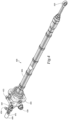
- FIG. 4 is a perspective view of an example hydraulic actuator 400.
- the hydraulic actuator 400 can be the example hydraulic actuator 24 of FIG. 2 or the example hydraulic actuator 34 of FIG. 3 .
- the hydraulic actuator 400 includes a housing 402 and a gimbal 404.
- the gimbal 404 can be configured to removably affix the housing 402 to a structural member, such as the example nacelle 14.
- a rod end 410 is configured to extend and retract relative to the housing 402.
- the rod end 410 can be configured to removably affix the hydraulic actuator 400 to a moveable element, such as the example moveable element 22 or the example moveable element 32.
- the rod end 410 is configured to extend and retract linearly, relative to the housing 402.
- the hydraulic actuator 400 includes an actuator deploy port 420 and an actuator stow port 422.
- the hydraulic actuator 400 is configured to extend the rod end 410 when fluid (e.g., hydraulic fluid) is flowed to the actuator deploy port 420 and retract the rod end 410 when fluid is flowed to the actuator stow port 422.
- fluid e.g., hydraulic fluid
- the housing 402 includes a mount point 440.
- the mount point 440 is configured for the removable attachment of a position sensor such as an LVDT.
- a control valve 450 is removably affixed to the hydraulic actuator 400 at the mount point 440.
- the control valve 450 is a hydraulic valve that includes an inlet fluid port 452 and an outlet fluid port 454.
- FIG. 5 is a cross sectional view of an example three-piece piston assembly 500 of the hydraulic actuator of FIG. 4 .
- the design and implementation of the example piston assembly 500 provides such strength, weight, and manufacturability.
- the piston assembly 500 solves this issue by splitting the piston into three pieces that can be assembled together, and the three pieces can be designed to use different materials that can be selected for their respective features, all within the small space of the piston head and while still using conventional technology in regards to manufacturing and assembly.
- the piston assembly 500 includes an actuator piston 510, a bushing 520, a lock nut 530, and an actuator lead screw 540.
- the actuator piston 510 has two radially interior surfaces that define an interior cavity 502.
- An axial portion 516 of the interior cavity 502 is defined by a surface 512 that is smooth in order to engage a smooth surface 522 the bushing 520.
- the axial portion 516 includes a piston face 513 at an end 518.
- the axial portion 516 of the interior cavity 502 is defined by a surface 514 that is threaded to engage a threaded surface 534 of the lock nut 530.
- the axial portion 517 of the interior cavity 502 is defined by a surface 512.
- the bushing 520 includes a surface 524.
- the surface 524 is defined as a radially interior thread configured to engage a threaded surface 542 of the actuator lead screw 540.
- a surface 522 is smooth and abuts the surface 512 of the interior cavity 502 of the piston assembly 500.
- a surface 544 of the actuator lead screw 540 is configured as a radially exterior surface that is smooth and designed to fit into the internal cavity 502 of the actuator piston 510.
- An axial surface of the bushing 520 includes a collection of tines 526 arranged as a castle feature and/or serrations.
- the lock nut 530 includes a collection of tines 536 configured to engagingly mate with the collection of tines 526.
- the tines 526 and the tines 536 are configured to engage axially in order to rotationally engage the lock nut 530 with the bushing 520.
- the lock nut 530 retains the bushing 520 within the internal cavity 502 of the actuator piston 510.
- the lock nut 530 prevents rotation of the bushing 520 relative to the lock nut 530 when the lock nut 530 is installed into the actuator piston 510.
- the lock nut 530 is located at an end 550 of the actuator piston 510 proximal to the piston head.
- the threaded surface 534 is configured to engage to a corresponding thread of the threaded surface 514 on the radially interior diameter of the actuator piston 510. In its assembled configuration, the threaded surface 534 matingly engages the threaded surface 514 in order to axially retain the actuator piston 510 and the lock nut 530.
- each of the actuator piston 510, the bushing 520, the lock nut 530, and the actuator lead screw 540 can be formed from different materials.
- the materials can be selected based on the purpose and/or performance characteristics of each of these components.
- the material used to manufacture the actuator piston 510 can be selected for high strength, such as 15-5 PH.
- the 15-5 PH alloy is martensitic in structure in the annealed condition and is further strengthened by a relatively low temperature heat treatment which precipitates a copper containing phase in the alloy.
- 15-5 PH is also referred to as XM-12 in some specifications.
- the material used to manufacture the bushing 520 can be selected for low-friction characteristics, such as GRAPH MO.
- GRAPH MO tool steel is an oil-hardening, graphitic tool steel that resists metal-to-metal sliding wear and galling.
- the steel contains a uniform dispersion of graphite particles which impart machinability and non-seizing characteristics.
- the graphite particles make the steel self-lubricating in dry environments, and help to retain oil in lubricated environments.
- GRAPH MO tool steel can be hardened to over 60 Rockwell C from a relatively low hardening temperature, which minimizes size change and distortion during heat treatment.
- the material used to manufacture the lock nut 530 can be selected for high strength, such as 15-5 PH, TOUGHMET, or similar materials.
- TOUGHMET is a high-strength, spinodally-hardened, copper nickel tin alloy that exhibits corrosion resistance, stress corrosion cracking resistance, anti-friction properties, is non-magnetic, and exhibits lubricity and wear resistance under severe loading conditions.
- Splitting the piston assembly 500 into multiple pieces of different materials connected by one threaded and one slotted interface can provide improved functionality, such as load capability.
- FIG. 6 is a cross sectional view of another example three-piece piston assembly 600 of the hydraulic actuator of FIG. 4 .
- the design and implementation of the example piston assembly 600 is a modification of the example piston assembly 500 of FIG. 5 .
- the embodiment shown in FIG.6 is not covered by the claimed invention.
- the piston assembly 600 differs from the piston assembly 500 by the inclusion of a locking pin 610.
- the locking pin 610 is configured to directly engage a lead screw nut 520' to a piston 510'.
- the piston assembly 600 includes an actuator piston 510', a bushing 520', a lock nut 530', and the actuator lead screw 540.
- the actuator piston 510' defines a portion of an interior cavity 612.
- the bushing 520' defines another portion of the interior cavity 612.
- the interior cavity 612 is defined with an axial shape that is configured to accept insertion of the locking pin 610.
- rotational forces between the actuator piston 510' and the bushing 520' are transferred primarily though the locking pin 610, and little or no rotational force is transmitted through a surface 514' that is threaded to engage a threaded surface 534'.
- FIG. 7 is a flow diagram of an example assembly process.
- the process 700 may be performed, for example, to assemble the example piston assembly 500 of FIG. 5 or the example piston assembly 6 of FIG. 6 .
- the description that follows uses the piston assembly 500 as an example for describing the process 700.
- other embodiments of the piston assembly 500 may be used to perform the process 700.
- the bushing 520 is inserted into the actuator piston 510.
- the lock nut 530 is then installed.
- the tines 526 engage the corresponding feature on the lock nut 530.
- the bushing 520 and lock nut 530 then rotate together during installation until the bushing 520 abuts the actuator piston 510. This configuration allows for convenient assembly of a multi-piece and multi-material synchronized actuator piston.
- a bushing is inserted into a cylindrical cavity defined by a piston inner surface of a piston.
- the bushing 620 is inserted into the internal cavity 502 defined in the actuator piston 510, such that the surface 522 is brought into contact with the surface 512.
- the piston inner surface can include a first axial portion, a piston face at a first end of the first axial portion, and a second axial portion at a second end of the first axial portion, where the helical piston thread is defined upon the piston inner surface.
- the actuator piston 510 has two radially interior surfaces that define an interior cavity 502.
- the axial portion 516 of the interior cavity 502 is defined by the surface 514 and includes the piston face 513 at the end 518.
- the axial portion 517 of the interior cavity 502 is defined by the surface 512.
- the piston inner surface is contacted with a bushing outer surface of a tubular cylindrical body of the bushing.
- the bushing include a tubular cylindrical body having a bushing outer surface configured to concentrically contact the piston inner surface.
- the bushing can include a tubular cylindrical body having a bushing inner surface, and a helical bushing thread defined upon the bushing inner surface.
- the bushing 520 includes a surface 524.
- the surface 524 is defined as a radially interior thread configured to engage a threaded surface 542 of the actuator lead screw 540.
- the surface 522 is smooth and abuts the surface 512 of the interior cavity 502 of the piston assembly 500.
- a lock nut is threaded onto a helical piston thread defined upon the piston.
- the lock nut can have a cylindrical outer surface and a helical nut thread defined upon the cylindrical outer surface, where the helical nut thread is configured to mate with a helical piston thread defined upon the piston inner surface.
- the surface 514 of the actuator piston 510 is threaded to engage the threaded surface 534 of the lock nut 530.
- the process 700 can also include axially constraining, by the threading, the bushing between the lock nut and a piston face at a first end of a first axial portion of the piston inner surface, wherein the helical piston thread is defined upon a second axial portion of the piston inner surface.
- the lock nut 530 retains the bushing 520 within the internal cavity 502 of the actuator piston 510.
- the lock nut 530 prevents rotation of the bushing 520 relative to the lock nut 530 when the lock nut 530 is installed into the actuator piston 510, and the threaded surface 534 matingly engages the threaded surface 514 in order to axially retain the actuator piston 510 and the lock nut 530.
- a cylindrical first collection of tines arranged upon an axial end of the bushing, is engaged with a cylindrical second collection of tines arranged upon an axial end of the lock nut.
- the tines 526 and the tines 536 are configured to engage axially in order to rotationally engage the lock nut 530 with the bushing 520.
- the process 700 can also include providing the piston assembly.
- the actuator piston 510, the bushing 520, and the lock nut 530 can be provided for assembly into the piston assembly 500.
- the process 700 can also include threading a lead screw through the cylindrical cavity, where the lead screw has a helical lead screw thread arranged to engage a helical bushing thread defined upon a tubular inner surface of the bushing.
- the surface 524 is defined as a radially interior thread configured to engage the threaded surface 542 of the actuator lead screw 540.
- the process 700 can also include rotating the lead screw relative to the piston, the bushing, and the lock nut, converting rotation of the lead screw into linear motion of the piston, the bushing, and the lock nut, and moving the piston, the bushing, and the lock nut linearly relative to the lead screw.
- the actuator lead screw 540 can be rotated relative to the assembled configuration of the actuator piston 510, the bushing 520, and the lock nut 530. As the actuator lead screw 540 rotates, the threaded surface 542 threads and/or unthreads into and/or out of the surface 524.
- the rotational movement of the actuator lead screw 540 is converted into linear movement of the assembled configuration of the actuator piston 510, the bushing 520, and the lock nut 530 relative to the actuator lead screw 540.
Landscapes
- Engineering & Computer Science (AREA)
- Mechanical Engineering (AREA)
- General Engineering & Computer Science (AREA)
- Physics & Mathematics (AREA)
- Fluid Mechanics (AREA)
- Chemical & Material Sciences (AREA)
- Combustion & Propulsion (AREA)
- Transmission Devices (AREA)
- Actuator (AREA)
Description
- This application claims priority to
U.S. Patent Application No. 16/401,713 filed on May 2, 2019 - The present invention relates to an assembly comprising a multiple piece piston. This piston can be used in an aircraft thrust reverser actuation system. The present invention further relates to a method of assembling such a multiple piece piston.
- Contemporary aircraft engines may include a thrust reverser actuation system (TRAS) to assist in reducing the aircraft speed during landing. Typical thrust reversers include one or more movable transcowls that, when in the active position, reverse at least a portion of the airflow passing through the engine.
- Mechanically synchronized locking actuators used in TRAS use pistons to maintain synchronization with other actuators through an acme lead screw and lead screw nut assembly. The TRAS actuators are expected to hold high loads in the locked position and achieve smooth synchronization for many cycles. This is typically done with a lead screw nut that has a radially interior threads to engage the lead screw. The lead screw nut typically also has a groove on the radially external diameter to engage a lock key (or lock fingers such as used in finger lock actuators) to mechanically lock the actuator when it is not in use. Examples of synchronized actuators incorporating key type locks are found in
US Patent No. 8,715,132 andUS Patent No. 8,932,176 . - Historically, piston assembly designs have been able to meet requirements with a lock nut material that achieves both high strength and low friction. In other historical piston assemblies, the locking feature is machined into the piston, but this method can be difficult from a manufacturing perspective and can lead to higher costs. Recently, aircraft loads have been increasing, and new designs will be needed to meet these requirements.
-
US2935048A describes an actuator assembly. The actuator assembly incorporates an oil circulation tube and a pair of pressure drop bushings control the circulation of cooling oil through the tube. The actuator assembly includes a cylinder having a reciprocable, piston therein capable of fluid pressure actuation in both directions. A rotatable member, or screw shaft, is journalled in the cylinder and operatively connected to the piston such that piston movement is dependent upon and effects rotation of the screw shaft. - The present invention is directed to an assembly defined in
claim 1 and a method of assembling a piston assembly defined in claim 6. The dependent claims depict advantageous embodiments of the present invention. - The systems and techniques described here may provide one or more of the following advantages. First, a three-piece piston can provide improved performance relative to one-piece designs. The components of the three-piece piston can made from different materials in order to increase the performance of the piston. The piston can include a lock key groove made out of a high strength material to react a load from load keys. The locking nut can be made from a high hardness material to reduce friction. The piston can be coated or otherwise treated to increase its wear properties.
- The details of one or more implementations are set forth in the accompanying drawings and the description below. Other features and advantages will be apparent from the description and drawings, and from the claims.
-
-
FIG. 1 is a schematic view of an example turbofan jet engine assembly with a portion of the outer nacelle cut away for clarity. -
FIG. 2 is a schematic view of the engine assembly ofFIG. 1 with an exemplary thrust reverser. -
FIG. 3 is a schematic view of the engine assembly ofFIG. 1 with an alternative exemplary thrust reverser. -
FIG. 4 is a perspective view of an example hydraulic actuator. -
FIG. 5 is a cross sectional view of an example three-piece piston assembly of the hydraulic actuator ofFIG. 4 . -
FIG. 6 is a cross sectional view of an another example three-piece piston assembly of the hydraulic actuator ofFIG. 4 that is not covered by the claimed invention. -
FIG. 7 is a flow diagram of an example process for assembling the example three-piece piston assembly ofFIG. 5 . - This document describes systems and techniques for reversing aircraft turbine engine airflow, including a three-piece piston assembly. A thrust reverser with at least one movable cowl element (i.e., at least one transcowl), which is movable to and from a reversing position, may be used to change the direction of the bypass airflow. In the reversing position, the movable cowl element may be configured to reverse at least a portion of the bypass airflow. As the moveable cowl element is moved into and out of the reversing position by a hydraulic actuator, the forces (e.g., thrust, air resistance) interacting with the moveable cowl element can cause sudden changes in load presented to the actuator. Such forces can be damaging to the system; for example, a hydraulic actuator may initially push the moveable cowl element from the stowed position toward the deployed position, and at some point mid-stroke the aerodynamic forces on the element may provide powerful additional forces that urge the moveable cowl element toward deployment. Such forces may cause the moveable cowl element and/or the actuator to hit their end of travel with an impact that is sufficient to cause damage to the system.
- In general, the systems described below overcome this problem by using a hydraulic valve that controls fluid flow through the hydraulic actuator. The valve is mechanically linked to the actuator in a manner such that the valve can vary the fluid flow through the actuator depending on the position of the actuator. The valve can be constructed such that when in use, the fluid flow through the actuator can be restricted at predetermined positions, such as near an end of travel to resist assistive aerodynamic loads, for example, to slow actuator deployment or to soften impacts against the end of travel.
- Conventional cascade type thrust reverser actuation systems have hydraulic actuators that include an arm that is attached to the moveable cowl element, and a feedback screw that moves in proportion to the arm. Such thrust reversers also have mounting points to which position sensors (e.g., LVDTs) can be attached. These position sensors are configured to sense the position of the feedback screw, and thereby provide a feedback signal that is representative of the position of the moveable cowl element. The valves described herein can be configured to attach to hydraulic actuators in place of such position sensors, and be actuated by the feedback screw.
-
FIG. 1 illustrates an example turbofanjet engine assembly 10 having aturbine engine 12, afan assembly 13, and anacelle 14. Portions of thenacelle 14 have been cut away for clarity. Thenacelle 14 surrounds theturbine engine 12 and defines an annular airflow path orannular bypass duct 16 through thejet engine assembly 10 to define a generally forward-to-aft bypass airflow path, as schematically illustrated by thearrow 18. A combustion airflow is schematically illustrated by thearrows 19. - A thrust reverser with at least one movable element, which is movable to and from a reversing position, may be used to change the direction of the bypass airflow. In the reversing position, the movable element may be configured to reverse at least a portion of the bypass airflow. There are several methods of obtaining reverse thrust on turbofan jet engine assemblies.
FIG. 2 schematically illustrates one example of a thrust reverser 20 that may be used in the turbofanjet engine assembly 10. The thrust reverser 20 includes amovable element 22. Themovable element 22 has been illustrated as a cowl portion that is capable of axial motion with respect to the forward portion of thenacelle 14. A hydraulic actuator 24 may be coupled to themovable element 22 to move themovable element 22 into and out of the reversing position. In the reversing position, as illustrated, themovable element 22 limits the annular bypass area between themovable element 22 and theturbine engine 12, it also opens up aportion 26 between themovable element 22 and the forward portion of thenacelle 14 such that the air flow path may be reversed as illustrated by thearrows 28. An optional deflector orflap 29 may be included to aid in directing the airflow path between themovable element 22 and the forward portion of thenacelle 14. -
FIG. 3 schematically illustrates an alternative example of athrust reverser 30. Thethrust reverser 30 includes amovable element 32. Themovable element 32 has been illustrated as a deflector, which may be built into a portion of thenacelle 14. Ahydraulic actuator 34 may be coupled to themovable element 32 to move themovable element 32 into and out of the reversing position. In the reversing position, shown in phantom and indicated at 36, themovable element 32 turns the air outward and forward to reverse its direction as illustrated by thearrows 38. An optional deflector orflap 39 may be included to aid in directing the airflow path outward. - In both illustrative examples, the thrust reverser changes the direction of the thrust force. Both the thrust reverser 20 and the
thrust reverser 30 have been described as hydraulically operated systems and a hydraulic actuator has been schematically illustrated. In some embodiments, the thrust reverser 20 and/or thethrust reverser 30 can be powered by other fluids (e.g., pneumatic), by electro-mechanical actuators, or by any other appropriate power source or actuator type. -
FIG. 4 is a perspective view of an examplehydraulic actuator 400. In some embodiments, thehydraulic actuator 400 can be the example hydraulic actuator 24 ofFIG. 2 or the examplehydraulic actuator 34 ofFIG. 3 . Thehydraulic actuator 400 includes ahousing 402 and agimbal 404. In some embodiments, thegimbal 404 can be configured to removably affix thehousing 402 to a structural member, such as theexample nacelle 14. - A rod end 410 is configured to extend and retract relative to the
housing 402. In some embodiments, the rod end 410 can be configured to removably affix thehydraulic actuator 400 to a moveable element, such as the examplemoveable element 22 or the examplemoveable element 32. The rod end 410 is configured to extend and retract linearly, relative to thehousing 402. - The
hydraulic actuator 400 includes an actuator deployport 420 and anactuator stow port 422. Thehydraulic actuator 400 is configured to extend the rod end 410 when fluid (e.g., hydraulic fluid) is flowed to the actuator deployport 420 and retract the rod end 410 when fluid is flowed to theactuator stow port 422. - The
housing 402 includes amount point 440. Themount point 440 is configured for the removable attachment of a position sensor such as an LVDT. However, in the illustrated example, acontrol valve 450 is removably affixed to thehydraulic actuator 400 at themount point 440. Thecontrol valve 450 is a hydraulic valve that includes aninlet fluid port 452 and an outlet fluid port 454. - As aircraft loads increase, new piston designs are needed in order to provide enough strength to maintain TRAS synchronization with other actuators through an acme lead screw and lead screw nut assembly, while also being lightweight and economical to manufacture.
FIG. 5 is a cross sectional view of an example three-piece piston assembly 500 of the hydraulic actuator ofFIG. 4 . In general, the design and implementation of theexample piston assembly 500 provides such strength, weight, and manufacturability. - In general, in order to meet larger loads, previous designs have implemented increases in lock nut sizes. However, increasing the lock nut size can significantly increase the overall size and weight of an actuator used in weight-sensitive applications such as aircraft. In general, the
piston assembly 500 solves this issue by splitting the piston into three pieces that can be assembled together, and the three pieces can be designed to use different materials that can be selected for their respective features, all within the small space of the piston head and while still using conventional technology in regards to manufacturing and assembly. - The
piston assembly 500 includes anactuator piston 510, abushing 520, alock nut 530, and anactuator lead screw 540. Theactuator piston 510 has two radially interior surfaces that define aninterior cavity 502. Anaxial portion 516 of theinterior cavity 502 is defined by asurface 512 that is smooth in order to engage asmooth surface 522 thebushing 520. Theaxial portion 516 includes a piston face 513 at an end 518. Theaxial portion 516 of theinterior cavity 502 is defined by asurface 514 that is threaded to engage a threadedsurface 534 of thelock nut 530. At anend 519, theaxial portion 517 of theinterior cavity 502 is defined by asurface 512. - The
bushing 520 includes asurface 524. Thesurface 524 is defined as a radially interior thread configured to engage a threadedsurface 542 of theactuator lead screw 540. Asurface 522 is smooth and abuts thesurface 512 of theinterior cavity 502 of thepiston assembly 500. - A
surface 544 of theactuator lead screw 540 is configured as a radially exterior surface that is smooth and designed to fit into theinternal cavity 502 of theactuator piston 510. - An axial surface of the
bushing 520 includes a collection oftines 526 arranged as a castle feature and/or serrations. Thelock nut 530 includes a collection of tines 536 configured to engagingly mate with the collection oftines 526. Thetines 526 and the tines 536 are configured to engage axially in order to rotationally engage thelock nut 530 with thebushing 520. - The
lock nut 530 retains thebushing 520 within theinternal cavity 502 of theactuator piston 510. Thelock nut 530 prevents rotation of thebushing 520 relative to thelock nut 530 when thelock nut 530 is installed into theactuator piston 510. Thelock nut 530 is located at anend 550 of theactuator piston 510 proximal to the piston head. The threadedsurface 534 is configured to engage to a corresponding thread of the threadedsurface 514 on the radially interior diameter of theactuator piston 510. In its assembled configuration, the threadedsurface 534 matingly engages the threadedsurface 514 in order to axially retain theactuator piston 510 and thelock nut 530. - In some embodiments, each of the
actuator piston 510, thebushing 520, thelock nut 530, and theactuator lead screw 540 can be formed from different materials. The materials can be selected based on the purpose and/or performance characteristics of each of these components. For example, the material used to manufacture theactuator piston 510 can be selected for high strength, such as 15-5 PH. The 15-5 PH alloy is martensitic in structure in the annealed condition and is further strengthened by a relatively low temperature heat treatment which precipitates a copper containing phase in the alloy. 15-5 PH is also referred to as XM-12 in some specifications. In another example, the material used to manufacture thebushing 520 can be selected for low-friction characteristics, such as GRAPH MO. GRAPH MO tool steel is an oil-hardening, graphitic tool steel that resists metal-to-metal sliding wear and galling. The steel contains a uniform dispersion of graphite particles which impart machinability and non-seizing characteristics. The graphite particles make the steel self-lubricating in dry environments, and help to retain oil in lubricated environments. GRAPH MO tool steel can be hardened to over 60 Rockwell C from a relatively low hardening temperature, which minimizes size change and distortion during heat treatment. In another example, the material used to manufacture thelock nut 530 can be selected for high strength, such as 15-5 PH, TOUGHMET, or similar materials. TOUGHMET is a high-strength, spinodally-hardened, copper nickel tin alloy that exhibits corrosion resistance, stress corrosion cracking resistance, anti-friction properties, is non-magnetic, and exhibits lubricity and wear resistance under severe loading conditions. Splitting thepiston assembly 500 into multiple pieces of different materials connected by one threaded and one slotted interface can provide improved functionality, such as load capability. -
FIG. 6 is a cross sectional view of another example three-piece piston assembly 600 of the hydraulic actuator ofFIG. 4 . In general, the design and implementation of theexample piston assembly 600 is a modification of theexample piston assembly 500 ofFIG. 5 . The embodiment shown inFIG.6 is not covered by the claimed invention. - In general, the
piston assembly 600 differs from thepiston assembly 500 by the inclusion of alocking pin 610. The locking pin 610is configured to directly engage a lead screw nut 520' to a piston 510'. - The
piston assembly 600 includes an actuator piston 510', a bushing 520', a lock nut 530', and theactuator lead screw 540. The actuator piston 510' defines a portion of aninterior cavity 612. The bushing 520' defines another portion of theinterior cavity 612. When the actuator piston 510' and the bushing 520' are assembled, theinterior cavity 612 is defined with an axial shape that is configured to accept insertion of thelocking pin 610. In use, rotational forces between the actuator piston 510' and the bushing 520' are transferred primarily though thelocking pin 610, and little or no rotational force is transmitted through a surface 514' that is threaded to engage a threaded surface 534'. -
FIG. 7 is a flow diagram of an example assembly process. Theprocess 700 may be performed, for example, to assemble theexample piston assembly 500 ofFIG. 5 or the example piston assembly 6 ofFIG. 6 . For clarity of presentation, the description that follows uses thepiston assembly 500 as an example for describing theprocess 700. However, other embodiments of thepiston assembly 500 may be used to perform theprocess 700. - In general, during installation the
bushing 520 is inserted into theactuator piston 510. Thelock nut 530 is then installed. Thetines 526 engage the corresponding feature on thelock nut 530. Thebushing 520 and locknut 530 then rotate together during installation until thebushing 520 abuts theactuator piston 510. This configuration allows for convenient assembly of a multi-piece and multi-material synchronized actuator piston. - At 710, a bushing is inserted into a cylindrical cavity defined by a piston inner surface of a piston. For example, the bushing 620 is inserted into the
internal cavity 502 defined in theactuator piston 510, such that thesurface 522 is brought into contact with thesurface 512. - In some implementations, the piston inner surface can include a first axial portion, a piston face at a first end of the first axial portion, and a second axial portion at a second end of the first axial portion, where the helical piston thread is defined upon the piston inner surface. For example, the
actuator piston 510 has two radially interior surfaces that define aninterior cavity 502. Theaxial portion 516 of theinterior cavity 502 is defined by thesurface 514 and includes the piston face 513 at the end 518. At theend 519, theaxial portion 517 of theinterior cavity 502 is defined by thesurface 512. - At 620, the piston inner surface is contacted with a bushing outer surface of a tubular cylindrical body of the bushing. In some implementations, the bushing include a tubular cylindrical body having a bushing outer surface configured to concentrically contact the piston inner surface. In some implementations, the bushing can include a tubular cylindrical body having a bushing inner surface, and a helical bushing thread defined upon the bushing inner surface. For example, the
bushing 520 includes asurface 524. Thesurface 524 is defined as a radially interior thread configured to engage a threadedsurface 542 of theactuator lead screw 540. Thesurface 522 is smooth and abuts thesurface 512 of theinterior cavity 502 of thepiston assembly 500. - At 730, a lock nut is threaded onto a helical piston thread defined upon the piston. In some implementations, the lock nut can have a cylindrical outer surface and a helical nut thread defined upon the cylindrical outer surface, where the helical nut thread is configured to mate with a helical piston thread defined upon the piston inner surface. For example, the
surface 514 of theactuator piston 510 is threaded to engage the threadedsurface 534 of thelock nut 530. - In some implementations, the
process 700 can also include axially constraining, by the threading, the bushing between the lock nut and a piston face at a first end of a first axial portion of the piston inner surface, wherein the helical piston thread is defined upon a second axial portion of the piston inner surface. For example, thelock nut 530 retains thebushing 520 within theinternal cavity 502 of theactuator piston 510. Thelock nut 530 prevents rotation of thebushing 520 relative to thelock nut 530 when thelock nut 530 is installed into theactuator piston 510, and the threadedsurface 534 matingly engages the threadedsurface 514 in order to axially retain theactuator piston 510 and thelock nut 530. - At 740, a cylindrical first collection of tines, arranged upon an axial end of the bushing, is engaged with a cylindrical second collection of tines arranged upon an axial end of the lock nut. For example, the
tines 526 and the tines 536 are configured to engage axially in order to rotationally engage thelock nut 530 with thebushing 520. - In some implementations, the
process 700 can also include providing the piston assembly. For example, theactuator piston 510, thebushing 520, and thelock nut 530 can be provided for assembly into thepiston assembly 500. - In some implementations, the
process 700 can also include threading a lead screw through the cylindrical cavity, where the lead screw has a helical lead screw thread arranged to engage a helical bushing thread defined upon a tubular inner surface of the bushing. For example, thesurface 524 is defined as a radially interior thread configured to engage the threadedsurface 542 of theactuator lead screw 540. - In some implementations, the
process 700 can also include rotating the lead screw relative to the piston, the bushing, and the lock nut, converting rotation of the lead screw into linear motion of the piston, the bushing, and the lock nut, and moving the piston, the bushing, and the lock nut linearly relative to the lead screw. For example, theactuator lead screw 540 can be rotated relative to the assembled configuration of theactuator piston 510, thebushing 520, and thelock nut 530. As theactuator lead screw 540 rotates, the threadedsurface 542 threads and/or unthreads into and/or out of thesurface 524. As theactuator lead screw 540 threads and unthreads, the rotational movement of theactuator lead screw 540 is converted into linear movement of the assembled configuration of theactuator piston 510, thebushing 520, and thelock nut 530 relative to theactuator lead screw 540. - Although a few implementations have been described in detail above, other modifications are possible. For example, the logic flows depicted in the figures do not require the particular order shown, or sequential order, to achieve desirable results. In addition, other steps may be provided, or steps may be eliminated, from the described flows, and other components may be added to, or removed from, the described systems. However, in any case, the scope of the invention is defined by the following claims.
Claims (11)
- An assembly (500) comprising:a piston (510) having a piston inner surface defining a cylindrical cavity and comprising:a first axial portion (516),a piston face (513) at a first end (518) of the first axial portion,a second axial portion (517) at a second end (519) of the first axial portion, anda helical piston thread (534) defined upon the piston inner surface;a bushing (520) configured to contact the piston inner surface, wherein the bushing comprises a tubular cylindrical body having i) a bushing outer surface (522) configured to concentrically contact the piston inner surface and ii) a bushing inner surface (534) having a helical bushing thread defined upon the bushing inner surface; anda lock nut (530) configured to engage the piston and the bushing,characterized in that the assembly further comprises a) a cylindrical first collection of tines (526) arranged upon an axial end of the bushing and b) a cylindrical second collection of tines (536) arranged upon an axial end of the lock nut configured to rotationally engage the cylindrical first collection of tines.
- The assembly of claim 1, wherein the lock nut comprises a cylindrical outer surface and a helical nut thread defined upon the cylindrical outer surface.
- The assembly of claim 2, wherein the helical nut thread is configured to mate with the helical piston thread defined upon the piston inner surface.
- The assembly of any of claims 1 to 3, further comprising a lead screw (540) arranged within the cylindrical cavity.
- The assembly of claim 4, wherein the lead screw comprises a helical lead screw thread arranged to engage the helical bushing thread defined upon the tubular inner surface of the bushing.
- A method of assembling a piston assembly (500), the method comprising:inserting (710) a bushing (520) into a cylindrical cavity defined by a piston inner surface of a piston (510), whereini) the piston inner surface comprises a first axial portion (516), a piston face (513) at a first end (518) of the first axial portion, a second axial portion (517) at a second end (519) of the first axial portion, and a helical piston thread (534) defined upon the piston inner surface, andii) the bushing comprises a tubular cylindrical body having a bushing outer surface (522) configured to concentrically contact the piston inner surface and a bushing inner surface (534) having a helical bushing thread defined upon the bushing inner surface;contacting (720) the piston inner surface with the bushing outer surface (522) of the tubular cylindrical body of the bushing; andthreading (730) a lock nut (530) onto the helical piston thread defined upon the piston;characterized in that the method further comprises rotationally engaging (740) a cylindrical first collection of tines (526) arranged upon an axial end of the bushing and a cylindrical second collection of tines (536) arranged upon an axial end of the lock nut.
- The method of claim 6, further comprising axially constraining, by the threading, the bushing between the lock nut and a piston face at a first end of a first axial portion of the piston inner surface, wherein the helical piston thread is defined upon a second axial portion of the piston inner surface.
- The method of claim 6 or 7, further comprising providing the piston assembly.
- The method of any of claims 6 to 8, wherein the lock nut comprises a cylindrical outer surface and a helical nut thread defined upon the cylindrical outer surface, wherein the helical nut thread is configured to mate with the helical piston thread defined upon the piston inner surface.
- The method of any of claims 6 to 9, further comprising threading a lead screw through the cylindrical cavity, wherein the lead screw comprises a helical lead screw thread arranged to engage the helical bushing thread defined upon the tubular inner surface of the bushing.
- The method of claim 10, further comprising:rotating the lead screw relative to the piston, the bushing, and the lock nut;converting rotation of the lead screw into linear motion of the piston, the bushing, and the lock nut; andmoving the piston, the bushing, and the lock nut linearly relative to the lead screw.
Applications Claiming Priority (2)
| Application Number | Priority Date | Filing Date | Title |
|---|---|---|---|
| US16/401,713 US11156186B2 (en) | 2019-05-02 | 2019-05-02 | Multiple piece piston |
| PCT/US2020/030509 WO2020223373A1 (en) | 2019-05-02 | 2020-04-29 | Multiple piece piston |
Publications (2)
| Publication Number | Publication Date |
|---|---|
| EP3963214A1 EP3963214A1 (en) | 2022-03-09 |
| EP3963214B1 true EP3963214B1 (en) | 2024-01-10 |
Family
ID=70922131
Family Applications (1)
| Application Number | Title | Priority Date | Filing Date |
|---|---|---|---|
| EP20729883.7A Active EP3963214B1 (en) | 2019-05-02 | 2020-04-29 | Multiple piece piston |
Country Status (4)
| Country | Link |
|---|---|
| US (2) | US11156186B2 (en) |
| EP (1) | EP3963214B1 (en) |
| CN (1) | CN114008334B (en) |
| WO (1) | WO2020223373A1 (en) |
Families Citing this family (1)
| Publication number | Priority date | Publication date | Assignee | Title |
|---|---|---|---|---|
| US11156186B2 (en) | 2019-05-02 | 2021-10-26 | Woodward, Inc. | Multiple piece piston |
Family Cites Families (17)
| Publication number | Priority date | Publication date | Assignee | Title |
|---|---|---|---|---|
| US2935048A (en) | 1957-08-29 | 1960-05-03 | Gen Motors Corp | Actuator assembly |
| US3092082A (en) * | 1961-10-30 | 1963-06-04 | Gen Motors Corp | Actuator assembly |
| US4442928A (en) * | 1981-10-02 | 1984-04-17 | The Bendix Corporation | Actuator |
| AUPM982794A0 (en) * | 1994-12-02 | 1995-01-05 | Advanced Engine Technology Pty Ltd | New and improved rotary engine |
| FR2818223B1 (en) * | 2000-12-14 | 2003-02-14 | Bosch Gmbh Robert | EMERGENCY BRAKE SERVOMOTOR COMPRISING RADIAL OBSTACLE LOCKING MEANS |
| US6971494B2 (en) * | 2004-01-13 | 2005-12-06 | Magna Drivetrain Of America, Inc. | Torque transfer coupling with friction clutch and hydraulic clutch actuator |
| US6945374B2 (en) * | 2004-02-04 | 2005-09-20 | Magna Drivetrain Of America, Inc. | Active torque coupling with hydraulically-actuated ball ramp clutch assembly |
| DE102007060472A1 (en) * | 2007-12-14 | 2009-06-18 | Mahle International Gmbh | Two-piece piston for an internal combustion engine |
| CN101614278A (en) * | 2009-08-03 | 2009-12-30 | 石家庄金刚内燃机零部件集团有限公司 | A kind of carbon material and metallic material built-up piston |
| US8715132B2 (en) | 2010-12-31 | 2014-05-06 | Woodward Hrt, Inc. | Linear actuator and method of operation thereof |
| CN102852896B (en) * | 2012-07-26 | 2015-09-30 | 沈姝君 | A kind of Double-action multistage hydraulic oil cylinder with solid piston rod |
| CN103032196B (en) * | 2012-12-21 | 2014-09-24 | 中国兵器工业集团第七0研究所 | Combined piston with built-in piston pin |
| CN202971381U (en) * | 2012-12-27 | 2013-06-05 | 宁波广天赛克思液压有限公司 | Pressure adjustable buffer overflow valve |
| CN103671679B (en) * | 2013-12-12 | 2016-03-16 | 北京二七轨道交通装备有限责任公司 | Piston rod, pneumatic cylinder and quarry tipper |
| CN108100922A (en) | 2016-11-25 | 2018-06-01 | 重庆键英液压机电有限公司 | The split type jack of piston rod |
| CN107503996B (en) | 2017-09-08 | 2019-04-09 | 王少斌 | A kind of integrating device of the control of motor precise synchronization hydraulic oil and fluid displacement |
| US11156186B2 (en) | 2019-05-02 | 2021-10-26 | Woodward, Inc. | Multiple piece piston |
-
2019
- 2019-05-02 US US16/401,713 patent/US11156186B2/en active Active
-
2020
- 2020-04-29 WO PCT/US2020/030509 patent/WO2020223373A1/en not_active Ceased
- 2020-04-29 CN CN202080048060.4A patent/CN114008334B/en active Active
- 2020-04-29 EP EP20729883.7A patent/EP3963214B1/en active Active
-
2021
- 2021-09-20 US US17/479,900 patent/US11555470B2/en active Active
Also Published As
| Publication number | Publication date |
|---|---|
| US20200347802A1 (en) | 2020-11-05 |
| EP3963214A1 (en) | 2022-03-09 |
| CN114008334B (en) | 2024-09-10 |
| US11156186B2 (en) | 2021-10-26 |
| US20220178329A1 (en) | 2022-06-09 |
| WO2020223373A1 (en) | 2020-11-05 |
| CN114008334A (en) | 2022-02-01 |
| US11555470B2 (en) | 2023-01-17 |
Similar Documents
| Publication | Publication Date | Title |
|---|---|---|
| EP3421772B1 (en) | Telescopic ballscrew actuator | |
| US20070212220A1 (en) | Controlled propeller pitch lock actuation system | |
| US10208658B2 (en) | Turbocharger wastegate actuator high temperature rod end with a spherical bearing and a method for operating the actuator | |
| US11255294B2 (en) | Thrust reverser velocity control valve | |
| US11555470B2 (en) | Multiple piece piston | |
| EP3931434B1 (en) | Traveling finger lock for an actuator | |
| DE3933169C2 (en) | ||
| US20050001095A1 (en) | Self-aligning thrust reverser system lock assembly | |
| EP3404245B1 (en) | Tertiary lock system for a thrust reverser | |
| EP3428435B1 (en) | Actuator for use in aircraft | |
| EP4155581A1 (en) | Polymeric thread insert for high load leadscrew and nut | |
| EP2851290B1 (en) | Propeller pitchlock system with a rotating interface | |
| US11788490B1 (en) | Traveling finger lock for an actuator | |
| CN119321432A (en) | Energy storage actuating system and control method | |
| US12435670B2 (en) | Air conduction system | |
| US20250020156A1 (en) | Nut design for actuator system |
Legal Events
| Date | Code | Title | Description |
|---|---|---|---|
| STAA | Information on the status of an ep patent application or granted ep patent |
Free format text: STATUS: UNKNOWN |
|
| STAA | Information on the status of an ep patent application or granted ep patent |
Free format text: STATUS: THE INTERNATIONAL PUBLICATION HAS BEEN MADE |
|
| PUAI | Public reference made under article 153(3) epc to a published international application that has entered the european phase |
Free format text: ORIGINAL CODE: 0009012 |
|
| STAA | Information on the status of an ep patent application or granted ep patent |
Free format text: STATUS: REQUEST FOR EXAMINATION WAS MADE |
|
| 17P | Request for examination filed |
Effective date: 20211102 |
|
| AK | Designated contracting states |
Kind code of ref document: A1 Designated state(s): AL AT BE BG CH CY CZ DE DK EE ES FI FR GB GR HR HU IE IS IT LI LT LU LV MC MK MT NL NO PL PT RO RS SE SI SK SM TR |
|
| DAV | Request for validation of the european patent (deleted) | ||
| DAX | Request for extension of the european patent (deleted) | ||
| GRAP | Despatch of communication of intention to grant a patent |
Free format text: ORIGINAL CODE: EPIDOSNIGR1 |
|
| STAA | Information on the status of an ep patent application or granted ep patent |
Free format text: STATUS: GRANT OF PATENT IS INTENDED |
|
| INTG | Intention to grant announced |
Effective date: 20230929 |
|
| P01 | Opt-out of the competence of the unified patent court (upc) registered |
Effective date: 20231020 |
|
| GRAS | Grant fee paid |
Free format text: ORIGINAL CODE: EPIDOSNIGR3 |
|
| GRAA | (expected) grant |
Free format text: ORIGINAL CODE: 0009210 |
|
| STAA | Information on the status of an ep patent application or granted ep patent |
Free format text: STATUS: THE PATENT HAS BEEN GRANTED |
|
| AK | Designated contracting states |
Kind code of ref document: B1 Designated state(s): AL AT BE BG CH CY CZ DE DK EE ES FI FR GB GR HR HU IE IS IT LI LT LU LV MC MK MT NL NO PL PT RO RS SE SI SK SM TR |
|
| REG | Reference to a national code |
Ref country code: GB Ref legal event code: FG4D |
|
| REG | Reference to a national code |
Ref country code: CH Ref legal event code: EP |
|
| REG | Reference to a national code |
Ref country code: DE Ref legal event code: R096 Ref document number: 602020024200 Country of ref document: DE |
|
| REG | Reference to a national code |
Ref country code: IE Ref legal event code: FG4D |
|
| REG | Reference to a national code |
Ref country code: LT Ref legal event code: MG9D |
|
| REG | Reference to a national code |
Ref country code: NL Ref legal event code: MP Effective date: 20240110 |
|
| REG | Reference to a national code |
Ref country code: AT Ref legal event code: MK05 Ref document number: 1649097 Country of ref document: AT Kind code of ref document: T Effective date: 20240110 |
|
| PG25 | Lapsed in a contracting state [announced via postgrant information from national office to epo] |
Ref country code: NL Free format text: LAPSE BECAUSE OF FAILURE TO SUBMIT A TRANSLATION OF THE DESCRIPTION OR TO PAY THE FEE WITHIN THE PRESCRIBED TIME-LIMIT Effective date: 20240110 |
|
| PG25 | Lapsed in a contracting state [announced via postgrant information from national office to epo] |
Ref country code: NL Free format text: LAPSE BECAUSE OF FAILURE TO SUBMIT A TRANSLATION OF THE DESCRIPTION OR TO PAY THE FEE WITHIN THE PRESCRIBED TIME-LIMIT Effective date: 20240110 |
|
| PG25 | Lapsed in a contracting state [announced via postgrant information from national office to epo] |
Ref country code: IS Free format text: LAPSE BECAUSE OF FAILURE TO SUBMIT A TRANSLATION OF THE DESCRIPTION OR TO PAY THE FEE WITHIN THE PRESCRIBED TIME-LIMIT Effective date: 20240510 |
|
| PG25 | Lapsed in a contracting state [announced via postgrant information from national office to epo] |
Ref country code: LT Free format text: LAPSE BECAUSE OF FAILURE TO SUBMIT A TRANSLATION OF THE DESCRIPTION OR TO PAY THE FEE WITHIN THE PRESCRIBED TIME-LIMIT Effective date: 20240110 |
|
| PG25 | Lapsed in a contracting state [announced via postgrant information from national office to epo] |
Ref country code: GR Free format text: LAPSE BECAUSE OF FAILURE TO SUBMIT A TRANSLATION OF THE DESCRIPTION OR TO PAY THE FEE WITHIN THE PRESCRIBED TIME-LIMIT Effective date: 20240411 |
|
| PG25 | Lapsed in a contracting state [announced via postgrant information from national office to epo] |
Ref country code: RS Free format text: LAPSE BECAUSE OF FAILURE TO SUBMIT A TRANSLATION OF THE DESCRIPTION OR TO PAY THE FEE WITHIN THE PRESCRIBED TIME-LIMIT Effective date: 20240410 Ref country code: HR Free format text: LAPSE BECAUSE OF FAILURE TO SUBMIT A TRANSLATION OF THE DESCRIPTION OR TO PAY THE FEE WITHIN THE PRESCRIBED TIME-LIMIT Effective date: 20240110 |
|
| PG25 | Lapsed in a contracting state [announced via postgrant information from national office to epo] |
Ref country code: ES Free format text: LAPSE BECAUSE OF FAILURE TO SUBMIT A TRANSLATION OF THE DESCRIPTION OR TO PAY THE FEE WITHIN THE PRESCRIBED TIME-LIMIT Effective date: 20240110 |
|
| PG25 | Lapsed in a contracting state [announced via postgrant information from national office to epo] |
Ref country code: AT Free format text: LAPSE BECAUSE OF FAILURE TO SUBMIT A TRANSLATION OF THE DESCRIPTION OR TO PAY THE FEE WITHIN THE PRESCRIBED TIME-LIMIT Effective date: 20240110 |
|
| PG25 | Lapsed in a contracting state [announced via postgrant information from national office to epo] |
Ref country code: RS Free format text: LAPSE BECAUSE OF FAILURE TO SUBMIT A TRANSLATION OF THE DESCRIPTION OR TO PAY THE FEE WITHIN THE PRESCRIBED TIME-LIMIT Effective date: 20240410 Ref country code: NO Free format text: LAPSE BECAUSE OF FAILURE TO SUBMIT A TRANSLATION OF THE DESCRIPTION OR TO PAY THE FEE WITHIN THE PRESCRIBED TIME-LIMIT Effective date: 20240410 Ref country code: LT Free format text: LAPSE BECAUSE OF FAILURE TO SUBMIT A TRANSLATION OF THE DESCRIPTION OR TO PAY THE FEE WITHIN THE PRESCRIBED TIME-LIMIT Effective date: 20240110 Ref country code: IS Free format text: LAPSE BECAUSE OF FAILURE TO SUBMIT A TRANSLATION OF THE DESCRIPTION OR TO PAY THE FEE WITHIN THE PRESCRIBED TIME-LIMIT Effective date: 20240510 Ref country code: HR Free format text: LAPSE BECAUSE OF FAILURE TO SUBMIT A TRANSLATION OF THE DESCRIPTION OR TO PAY THE FEE WITHIN THE PRESCRIBED TIME-LIMIT Effective date: 20240110 Ref country code: GR Free format text: LAPSE BECAUSE OF FAILURE TO SUBMIT A TRANSLATION OF THE DESCRIPTION OR TO PAY THE FEE WITHIN THE PRESCRIBED TIME-LIMIT Effective date: 20240411 Ref country code: ES Free format text: LAPSE BECAUSE OF FAILURE TO SUBMIT A TRANSLATION OF THE DESCRIPTION OR TO PAY THE FEE WITHIN THE PRESCRIBED TIME-LIMIT Effective date: 20240110 Ref country code: BG Free format text: LAPSE BECAUSE OF FAILURE TO SUBMIT A TRANSLATION OF THE DESCRIPTION OR TO PAY THE FEE WITHIN THE PRESCRIBED TIME-LIMIT Effective date: 20240110 Ref country code: AT Free format text: LAPSE BECAUSE OF FAILURE TO SUBMIT A TRANSLATION OF THE DESCRIPTION OR TO PAY THE FEE WITHIN THE PRESCRIBED TIME-LIMIT Effective date: 20240110 |
|
| PG25 | Lapsed in a contracting state [announced via postgrant information from national office to epo] |
Ref country code: PL Free format text: LAPSE BECAUSE OF FAILURE TO SUBMIT A TRANSLATION OF THE DESCRIPTION OR TO PAY THE FEE WITHIN THE PRESCRIBED TIME-LIMIT Effective date: 20240110 Ref country code: PT Free format text: LAPSE BECAUSE OF FAILURE TO SUBMIT A TRANSLATION OF THE DESCRIPTION OR TO PAY THE FEE WITHIN THE PRESCRIBED TIME-LIMIT Effective date: 20240510 |
|
| PG25 | Lapsed in a contracting state [announced via postgrant information from national office to epo] |
Ref country code: SE Free format text: LAPSE BECAUSE OF FAILURE TO SUBMIT A TRANSLATION OF THE DESCRIPTION OR TO PAY THE FEE WITHIN THE PRESCRIBED TIME-LIMIT Effective date: 20240110 Ref country code: PT Free format text: LAPSE BECAUSE OF FAILURE TO SUBMIT A TRANSLATION OF THE DESCRIPTION OR TO PAY THE FEE WITHIN THE PRESCRIBED TIME-LIMIT Effective date: 20240510 Ref country code: PL Free format text: LAPSE BECAUSE OF FAILURE TO SUBMIT A TRANSLATION OF THE DESCRIPTION OR TO PAY THE FEE WITHIN THE PRESCRIBED TIME-LIMIT Effective date: 20240110 Ref country code: LV Free format text: LAPSE BECAUSE OF FAILURE TO SUBMIT A TRANSLATION OF THE DESCRIPTION OR TO PAY THE FEE WITHIN THE PRESCRIBED TIME-LIMIT Effective date: 20240110 |
|
| PG25 | Lapsed in a contracting state [announced via postgrant information from national office to epo] |
Ref country code: DK Free format text: LAPSE BECAUSE OF FAILURE TO SUBMIT A TRANSLATION OF THE DESCRIPTION OR TO PAY THE FEE WITHIN THE PRESCRIBED TIME-LIMIT Effective date: 20240110 |
|
| REG | Reference to a national code |
Ref country code: DE Ref legal event code: R097 Ref document number: 602020024200 Country of ref document: DE |
|
| PG25 | Lapsed in a contracting state [announced via postgrant information from national office to epo] |
Ref country code: SM Free format text: LAPSE BECAUSE OF FAILURE TO SUBMIT A TRANSLATION OF THE DESCRIPTION OR TO PAY THE FEE WITHIN THE PRESCRIBED TIME-LIMIT Effective date: 20240110 |
|
| PG25 | Lapsed in a contracting state [announced via postgrant information from national office to epo] |
Ref country code: EE Free format text: LAPSE BECAUSE OF FAILURE TO SUBMIT A TRANSLATION OF THE DESCRIPTION OR TO PAY THE FEE WITHIN THE PRESCRIBED TIME-LIMIT Effective date: 20240110 Ref country code: CZ Free format text: LAPSE BECAUSE OF FAILURE TO SUBMIT A TRANSLATION OF THE DESCRIPTION OR TO PAY THE FEE WITHIN THE PRESCRIBED TIME-LIMIT Effective date: 20240110 |
|
| PG25 | Lapsed in a contracting state [announced via postgrant information from national office to epo] |
Ref country code: SK Free format text: LAPSE BECAUSE OF FAILURE TO SUBMIT A TRANSLATION OF THE DESCRIPTION OR TO PAY THE FEE WITHIN THE PRESCRIBED TIME-LIMIT Effective date: 20240110 |
|
| PG25 | Lapsed in a contracting state [announced via postgrant information from national office to epo] |
Ref country code: SM Free format text: LAPSE BECAUSE OF FAILURE TO SUBMIT A TRANSLATION OF THE DESCRIPTION OR TO PAY THE FEE WITHIN THE PRESCRIBED TIME-LIMIT Effective date: 20240110 Ref country code: SK Free format text: LAPSE BECAUSE OF FAILURE TO SUBMIT A TRANSLATION OF THE DESCRIPTION OR TO PAY THE FEE WITHIN THE PRESCRIBED TIME-LIMIT Effective date: 20240110 Ref country code: RO Free format text: LAPSE BECAUSE OF FAILURE TO SUBMIT A TRANSLATION OF THE DESCRIPTION OR TO PAY THE FEE WITHIN THE PRESCRIBED TIME-LIMIT Effective date: 20240110 Ref country code: EE Free format text: LAPSE BECAUSE OF FAILURE TO SUBMIT A TRANSLATION OF THE DESCRIPTION OR TO PAY THE FEE WITHIN THE PRESCRIBED TIME-LIMIT Effective date: 20240110 Ref country code: DK Free format text: LAPSE BECAUSE OF FAILURE TO SUBMIT A TRANSLATION OF THE DESCRIPTION OR TO PAY THE FEE WITHIN THE PRESCRIBED TIME-LIMIT Effective date: 20240110 Ref country code: CZ Free format text: LAPSE BECAUSE OF FAILURE TO SUBMIT A TRANSLATION OF THE DESCRIPTION OR TO PAY THE FEE WITHIN THE PRESCRIBED TIME-LIMIT Effective date: 20240110 |
|
| PLBE | No opposition filed within time limit |
Free format text: ORIGINAL CODE: 0009261 |
|
| STAA | Information on the status of an ep patent application or granted ep patent |
Free format text: STATUS: NO OPPOSITION FILED WITHIN TIME LIMIT |
|
| PG25 | Lapsed in a contracting state [announced via postgrant information from national office to epo] |
Ref country code: MC Free format text: LAPSE BECAUSE OF FAILURE TO SUBMIT A TRANSLATION OF THE DESCRIPTION OR TO PAY THE FEE WITHIN THE PRESCRIBED TIME-LIMIT Effective date: 20240110 |
|
| PG25 | Lapsed in a contracting state [announced via postgrant information from national office to epo] |
Ref country code: MC Free format text: LAPSE BECAUSE OF FAILURE TO SUBMIT A TRANSLATION OF THE DESCRIPTION OR TO PAY THE FEE WITHIN THE PRESCRIBED TIME-LIMIT Effective date: 20240110 |
|
| REG | Reference to a national code |
Ref country code: CH Ref legal event code: PL |
|
| PG25 | Lapsed in a contracting state [announced via postgrant information from national office to epo] |
Ref country code: IT Free format text: LAPSE BECAUSE OF FAILURE TO SUBMIT A TRANSLATION OF THE DESCRIPTION OR TO PAY THE FEE WITHIN THE PRESCRIBED TIME-LIMIT Effective date: 20240110 |
|
| PG25 | Lapsed in a contracting state [announced via postgrant information from national office to epo] |
Ref country code: LU Free format text: LAPSE BECAUSE OF NON-PAYMENT OF DUE FEES Effective date: 20240429 |
|
| 26N | No opposition filed |
Effective date: 20241011 |
|
| REG | Reference to a national code |
Ref country code: BE Ref legal event code: MM Effective date: 20240430 |
|
| PG25 | Lapsed in a contracting state [announced via postgrant information from national office to epo] |
Ref country code: LU Free format text: LAPSE BECAUSE OF NON-PAYMENT OF DUE FEES Effective date: 20240429 Ref country code: IT Free format text: LAPSE BECAUSE OF FAILURE TO SUBMIT A TRANSLATION OF THE DESCRIPTION OR TO PAY THE FEE WITHIN THE PRESCRIBED TIME-LIMIT Effective date: 20240110 |
|
| PG25 | Lapsed in a contracting state [announced via postgrant information from national office to epo] |
Ref country code: BE Free format text: LAPSE BECAUSE OF NON-PAYMENT OF DUE FEES Effective date: 20240430 |
|
| PG25 | Lapsed in a contracting state [announced via postgrant information from national office to epo] |
Ref country code: BE Free format text: LAPSE BECAUSE OF NON-PAYMENT OF DUE FEES Effective date: 20240430 Ref country code: CH Free format text: LAPSE BECAUSE OF NON-PAYMENT OF DUE FEES Effective date: 20240430 |
|
| PG25 | Lapsed in a contracting state [announced via postgrant information from national office to epo] |
Ref country code: IE Free format text: LAPSE BECAUSE OF NON-PAYMENT OF DUE FEES Effective date: 20240429 |
|
| PG25 | Lapsed in a contracting state [announced via postgrant information from national office to epo] |
Ref country code: SI Free format text: LAPSE BECAUSE OF FAILURE TO SUBMIT A TRANSLATION OF THE DESCRIPTION OR TO PAY THE FEE WITHIN THE PRESCRIBED TIME-LIMIT Effective date: 20240110 |
|
| PGFP | Annual fee paid to national office [announced via postgrant information from national office to epo] |
Ref country code: DE Payment date: 20250429 Year of fee payment: 6 |
|
| PGFP | Annual fee paid to national office [announced via postgrant information from national office to epo] |
Ref country code: GB Payment date: 20250428 Year of fee payment: 6 |
|
| PGFP | Annual fee paid to national office [announced via postgrant information from national office to epo] |
Ref country code: FR Payment date: 20250425 Year of fee payment: 6 |
|
| PG25 | Lapsed in a contracting state [announced via postgrant information from national office to epo] |
Ref country code: CY Free format text: LAPSE BECAUSE OF FAILURE TO SUBMIT A TRANSLATION OF THE DESCRIPTION OR TO PAY THE FEE WITHIN THE PRESCRIBED TIME-LIMIT; INVALID AB INITIO Effective date: 20200429 |
|
| PG25 | Lapsed in a contracting state [announced via postgrant information from national office to epo] |
Ref country code: HU Free format text: LAPSE BECAUSE OF FAILURE TO SUBMIT A TRANSLATION OF THE DESCRIPTION OR TO PAY THE FEE WITHIN THE PRESCRIBED TIME-LIMIT; INVALID AB INITIO Effective date: 20200429 |
|
| PG25 | Lapsed in a contracting state [announced via postgrant information from national office to epo] |
Ref country code: FI Free format text: LAPSE BECAUSE OF FAILURE TO SUBMIT A TRANSLATION OF THE DESCRIPTION OR TO PAY THE FEE WITHIN THE PRESCRIBED TIME-LIMIT Effective date: 20240110 |