EP3963198B1 - Thrust reverser cascade including an acoustic treatment - Google Patents
Thrust reverser cascade including an acoustic treatment Download PDFInfo
- Publication number
- EP3963198B1 EP3963198B1 EP20715881.7A EP20715881A EP3963198B1 EP 3963198 B1 EP3963198 B1 EP 3963198B1 EP 20715881 A EP20715881 A EP 20715881A EP 3963198 B1 EP3963198 B1 EP 3963198B1
- Authority
- EP
- European Patent Office
- Prior art keywords
- partitions
- cascade
- turbomachine
- partition
- mobile
- Prior art date
- Legal status (The legal status is an assumption and is not a legal conclusion. Google has not performed a legal analysis and makes no representation as to the accuracy of the status listed.)
- Active
Links
- 238000005192 partition Methods 0.000 claims description 117
- 238000013519 translation Methods 0.000 claims description 42
- 230000001360 synchronised effect Effects 0.000 claims description 3
- 238000007789 sealing Methods 0.000 claims 1
- 230000014616 translation Effects 0.000 description 28
- 238000011144 upstream manufacturing Methods 0.000 description 8
- 238000010521 absorption reaction Methods 0.000 description 4
- 230000002745 absorbent Effects 0.000 description 2
- 239000002250 absorbent Substances 0.000 description 2
- 238000005452 bending Methods 0.000 description 2
- 230000015572 biosynthetic process Effects 0.000 description 2
- 238000005516 engineering process Methods 0.000 description 2
- 239000012530 fluid Substances 0.000 description 2
- 230000003993 interaction Effects 0.000 description 2
- 210000002105 tongue Anatomy 0.000 description 2
- 239000002131 composite material Substances 0.000 description 1
- 230000008602 contraction Effects 0.000 description 1
- 230000001627 detrimental effect Effects 0.000 description 1
- 238000003780 insertion Methods 0.000 description 1
- 230000037431 insertion Effects 0.000 description 1
- 230000005855 radiation Effects 0.000 description 1
- 239000007787 solid Substances 0.000 description 1
- 210000003462 vein Anatomy 0.000 description 1
Images


Classifications
-
- F—MECHANICAL ENGINEERING; LIGHTING; HEATING; WEAPONS; BLASTING
- F02—COMBUSTION ENGINES; HOT-GAS OR COMBUSTION-PRODUCT ENGINE PLANTS
- F02K—JET-PROPULSION PLANTS
- F02K1/00—Plants characterised by the form or arrangement of the jet pipe or nozzle; Jet pipes or nozzles peculiar thereto
- F02K1/54—Nozzles having means for reversing jet thrust
- F02K1/64—Reversing fan flow
- F02K1/70—Reversing fan flow using thrust reverser flaps or doors mounted on the fan housing
- F02K1/72—Reversing fan flow using thrust reverser flaps or doors mounted on the fan housing the aft end of the fan housing being movable to uncover openings in the fan housing for the reversed flow
-
- B—PERFORMING OPERATIONS; TRANSPORTING
- B64—AIRCRAFT; AVIATION; COSMONAUTICS
- B64D—EQUIPMENT FOR FITTING IN OR TO AIRCRAFT; FLIGHT SUITS; PARACHUTES; ARRANGEMENT OR MOUNTING OF POWER PLANTS OR PROPULSION TRANSMISSIONS IN AIRCRAFT
- B64D33/00—Arrangements in aircraft of power plant parts or auxiliaries not otherwise provided for
- B64D33/04—Arrangements in aircraft of power plant parts or auxiliaries not otherwise provided for of exhaust outlets or jet pipes
- B64D33/06—Silencing exhaust or propulsion jets
-
- F—MECHANICAL ENGINEERING; LIGHTING; HEATING; WEAPONS; BLASTING
- F02—COMBUSTION ENGINES; HOT-GAS OR COMBUSTION-PRODUCT ENGINE PLANTS
- F02C—GAS-TURBINE PLANTS; AIR INTAKES FOR JET-PROPULSION PLANTS; CONTROLLING FUEL SUPPLY IN AIR-BREATHING JET-PROPULSION PLANTS
- F02C7/00—Features, components parts, details or accessories, not provided for in, or of interest apart form groups F02C1/00 - F02C6/00; Air intakes for jet-propulsion plants
- F02C7/24—Heat or noise insulation
-
- F—MECHANICAL ENGINEERING; LIGHTING; HEATING; WEAPONS; BLASTING
- F02—COMBUSTION ENGINES; HOT-GAS OR COMBUSTION-PRODUCT ENGINE PLANTS
- F02K—JET-PROPULSION PLANTS
- F02K1/00—Plants characterised by the form or arrangement of the jet pipe or nozzle; Jet pipes or nozzles peculiar thereto
- F02K1/78—Other construction of jet pipes
- F02K1/82—Jet pipe walls, e.g. liners
- F02K1/827—Sound absorbing structures or liners
-
- F—MECHANICAL ENGINEERING; LIGHTING; HEATING; WEAPONS; BLASTING
- F05—INDEXING SCHEMES RELATING TO ENGINES OR PUMPS IN VARIOUS SUBCLASSES OF CLASSES F01-F04
- F05D—INDEXING SCHEME FOR ASPECTS RELATING TO NON-POSITIVE-DISPLACEMENT MACHINES OR ENGINES, GAS-TURBINES OR JET-PROPULSION PLANTS
- F05D2240/00—Components
- F05D2240/10—Stators
- F05D2240/12—Fluid guiding means, e.g. vanes
- F05D2240/129—Cascades, i.e. assemblies of similar profiles acting in parallel
-
- F—MECHANICAL ENGINEERING; LIGHTING; HEATING; WEAPONS; BLASTING
- F05—INDEXING SCHEMES RELATING TO ENGINES OR PUMPS IN VARIOUS SUBCLASSES OF CLASSES F01-F04
- F05D—INDEXING SCHEME FOR ASPECTS RELATING TO NON-POSITIVE-DISPLACEMENT MACHINES OR ENGINES, GAS-TURBINES OR JET-PROPULSION PLANTS
- F05D2250/00—Geometry
- F05D2250/90—Variable geometry
-
- F—MECHANICAL ENGINEERING; LIGHTING; HEATING; WEAPONS; BLASTING
- F05—INDEXING SCHEMES RELATING TO ENGINES OR PUMPS IN VARIOUS SUBCLASSES OF CLASSES F01-F04
- F05D—INDEXING SCHEME FOR ASPECTS RELATING TO NON-POSITIVE-DISPLACEMENT MACHINES OR ENGINES, GAS-TURBINES OR JET-PROPULSION PLANTS
- F05D2260/00—Function
- F05D2260/96—Preventing, counteracting or reducing vibration or noise
- F05D2260/963—Preventing, counteracting or reducing vibration or noise by Helmholtz resonators
-
- Y—GENERAL TAGGING OF NEW TECHNOLOGICAL DEVELOPMENTS; GENERAL TAGGING OF CROSS-SECTIONAL TECHNOLOGIES SPANNING OVER SEVERAL SECTIONS OF THE IPC; TECHNICAL SUBJECTS COVERED BY FORMER USPC CROSS-REFERENCE ART COLLECTIONS [XRACs] AND DIGESTS
- Y02—TECHNOLOGIES OR APPLICATIONS FOR MITIGATION OR ADAPTATION AGAINST CLIMATE CHANGE
- Y02T—CLIMATE CHANGE MITIGATION TECHNOLOGIES RELATED TO TRANSPORTATION
- Y02T50/00—Aeronautics or air transport
- Y02T50/60—Efficient propulsion technologies, e.g. for aircraft
Definitions
- the invention relates to the acoustic processing of sound waves emitted by a turbomachine of an aircraft, and more particularly the processing of sound waves at the level of the thrust reversers of the turbomachine.
- One of the ways to attenuate this acoustic radiation is to integrate acoustic treatment means at the surfaces in contact with the sound waves.
- the acoustic treatment of a turbojet and more precisely of the noise radiated by the interaction between the rotor and its environment, is carried out using absorbent panels placed at the level of the wetted surfaces of the conduit in which the waves propagate. sound.
- wetted surfaces we mean surfaces in contact with a fluid flow.
- These panels are generally sandwich-type composite materials trapping a honeycomb forming sound absorption cells.
- the radial bulk, that is to say the radial thickness, of the acoustic treatment panels depends on the targeted treatment frequency to obtain a maximum efficiency in terms of sound attenuation.
- a turbomachine generally includes thrust reversers.
- thrust reversers There are mainly two thrust reverser technologies which are based on the action of a grid.
- gate thrust reversers fixed gate thrust reversers and sliding gate thrust reversers.
- a grid according to the prior art is disclosed in the document US2017370325 .
- FIGS. 1A and 1B are presented schematic sectional views in a longitudinal plane of a turbomachine 1 according to a first embodiment known from the state of the art respectively in an inactivated thrust reversal position and in an activated thrust reversal position .
- the turbomachine 1 comprises a nacelle 2 with symmetry of revolution around an axis primary rectifier stage 5, a secondary rectifier stage 6, and a gate thrust reversal device 7 comprising a grid 8.
- the grid 8 is embedded, that is to say integral, with an upstream part 21 of the nacelle 2 and in slide connection with a downstream part 22 of the nacelle 2, the upstream and downstream being defined in relation to the direction of flow of a gas flow F in the turbomachine 1.
- the downstream part 22 of the nacelle 2 reveals the grid 8 which becomes the only interface between the internal flow of the nacelle 2 and the ambient environment in which the turbomachine 1 evolves.
- FIGS. 2A and 2B are presented schematic sectional views in a longitudinal plane of a turbomachine 1 according to a second embodiment known from the state of the art respectively in an inactive thrust reversal position and in an activated thrust reversal position .
- the grid 8 is in sliding connection relative to the upstream part 21 of the nacelle 2 and in connection with embedding relative to the downstream part 22 of the nacelle 2.
- the downstream part 22 of the nacelle 2 drives the grid 8 out of the nacelle 2 to position it at the interface between the internal flow to nacelle 2 and the ambient environment.
- Thrust reversers represent a cost, mass and bulk that are very detrimental to the performance of the propulsion unit, even though they are only used at the end of the landing phase.
- the volume that they use in the nacelle cannot in particular be used, in the state of the art, for the acoustic treatment of the sound waves emitted by the turbomachine.
- a known practice of integrating acoustic treatment classic consists of integrating acoustic panels into the cavities of the reverser doors. This practice simply consists of integrating classic absorbent panels into the available volumes, as is done in the fan housing.
- the invention aims to provide a grid of a grid thrust reverser which allows, when the grid is mounted in a thrust reverser of a turbomachine, both to redirect an air flow upstream of the turbomachine outside the nacelle, to minimize pressure losses through the grid and to maximize sound absorption efficiency.
- An object of the invention proposes a grid for a thrust reverser device intended to be mounted on a turbomachine of an aircraft, the grid comprising first partitions extending in a first direction, second fixed partitions extending in a second direction orthogonal to the first direction, and a frame inside which the first and second partitions extend, the frame comprising at least two fixed walls extending in the first direction, and at least a part of each first partition extending between two second partitions in a plane comprising the first and second directions.
- At least one first partition is movable in the second direction between a first position in which said at least one first partition is distant, in the second direction, from said fixed walls of the frame to form a plurality of resonant cavities with the first partitions and the fixed walls of the frame, and a second position in which said at least one first partition is in contact with a fixed wall or other first partition.
- the number of cells differs greatly between an inverter grid and an acoustic panel. This difference is due to the desired properties which are not the same.
- a thrust reverser grille is usually characterized by a metallic structure, dimensioned so as to withstand the aerodynamic load to which it is subjected during the thrust reversal phase. This structure also generates pressure losses.
- a cell is a volume made up of four walls through which a fluid can flow. Having too high a density of cells can harm the effectiveness of the thrust reverser due to excessive resistance to the passage of air.
- acoustic panel structures do not undergo aerodynamic stress.
- the partitions which constitute them are very thin and their small volume makes it possible to optimize the tuning frequency of the panel, that is to say the maximum attenuation frequency.
- the second partitions are intended to be oriented in a direction orthogonal to the direction of flow of a gas flow inside a turbomachine comprising a thrust reversal device equipped with such a grid.
- the second partitions oriented in an azimuthal or radial direction of the turbomachine, are essential to guarantee the thrust reversal functionality. It is in fact thanks to these second partitions that the air flow circulating in a vein, inside the nacelle in which the thrust reversal device is mounted, can be captured and reoriented upstream of the turbomachine, relative to the direction of flow of the flow inside of the nacelle, outside the nacelle.
- the first partitions are intended to be oriented according to the direction of the gas flow inside a turbomachine comprising a thrust reversal device equipped with such a grid.
- the first partitions oriented in an axial direction of the turbomachine, are not essential for the thrust reversal functionality.
- they allow the formation of resonant cavities making it possible to attenuate acoustic waves generated by the turbomachine.
- the mobility in the second direction of at least a first partition of the grid offers the possibility of modifying the number of cells of the grid depending on the mode of operation of the grid, to have for example, for the same given volume included in the first direction between two second partitions or a second partition and the frame, a single large cell or at least two smaller cells depending on the number of second movable partitions.
- the mobility of at least a first partition makes it possible to vary the number of cells to limit this number in “thrust reversal” mode, and increase this number in “acoustic treatment” mode.
- each first movable partition can comprise notches shaped to accommodate a second partition and allow said first partition to move along the second partitions, and each notch can comprise a seal making it possible to seal the notch .
- This conformation makes it possible to improve the formation of cells in resonant cavities when the grid operates in acoustic treatment mode by limiting acoustic leaks between cells.
- the joints of the notches can be brush or tongue joints.
- the grid can comprise at least two first movable partitions and at least one first translation system. partitions comprising an actuator and at least two connecting rods comprising a first and a second end, the second ends of the connecting rods of the same translation system being connected together to form a common pivot connection connected to the actuator, and the first end of each connecting rod of the same translation system being fixed in pivotal connection to a first movable partition.
- the grid may comprise at least one pair of translation systems of first partitions, the translation systems of the same pair of systems being connected to the same first movable partitions.
- the use of two translation systems to move the same or the same first movable partitions makes it possible to have two fixing points on the first movable partitions and thus to reduce the mechanical constraints imposed on the same fixing point and to reduce deformations. of the first movable partitions during translations.
- said at least one first movable partition may comprise, in the first direction, a first and a second end, the first ends of the connecting rods of a first system of a pair of systems being fixed in connection pivoting at the first ends of first movable partitions and the first ends of the connecting rods of a second system of the same pair of systems being fixed in pivotal connection to the second ends of the same first movable partitions.
- connection of the translation systems of the same pair of systems at the two ends of the first movable partitions of the grid makes it possible to facilitate translations, by minimizing the bending stresses in the movable partitions.
- the actuators of the translation systems of the same pair of translation systems can be mechanically connected together.
- the connecting rods connected to first partitions arranged between two fixed walls successively arranged in the second direction have a length of between half a time and one time the distance separating said two successive fixed walls.
- more than two first movable partitions are arranged between two fixed walls successively arranged in the second direction, and the connecting rods connected to first partitions arranged between said two successive fixed walls have different lengths from each other. .
- the actuator of said at least one translation system can be a pneumatic or electric actuator configured to move the first movable partitions apart from each other up to the first position or bring them closer together. one from the other to the second position.
- the thickness of the first partitions can be between 0.5 mm and 4 mm to be as thin as possible to minimize the mass and the pressure losses in the grid.
- the thickness of the first partitions is measured in the second direction.
- the grid may include stops positioned on the grid to stop the translation of the first movable partitions in the first position to obtain precise positioning.
- a grid thrust reversal device for a turbomachine of an aircraft characterized in that it comprises at least one grid as defined above.
- the actuator of said at least one translation system is configured to move the first movable partitions apart from each other up to the first position or bring them closer together. the other up to the second position synchronously with the triggering of the thrust reverser device.
- the synchronization of the actuator with the triggering of the thrust reversal device makes it possible to exert a translation force on all the points of connection allowing the mobile partition structure to be deployed or folded depending on the operating mode of the thrust reverser device, the thrust reverser device being able to be inactive, that is to say in an acoustic treatment mode , or active, that is to say in a thrust reversal mode.
- turbomachine intended to be mounted on an aircraft, the turbomachine comprising a nacelle with symmetry of revolution defining an axial direction and a radial direction, the nacelle comprising a thickness in the radial direction and a housing extending in the axial direction in its thickness for receiving a gate of a gate thrust reverser device.
- the turbomachine can comprise a grid thrust reversal device as defined above, the grid being arranged, when thrust reversal is not required, in the corresponding housing of the nacelle of the turbomachine with the first partitions extending in the axial direction and the radial direction and the second partitions extending in the radial direction and in a direction orthogonal to the axial direction and the radial direction, the first direction corresponding to the axial direction.
- the nacelle may comprise a perforated wall forming a radially internal wall of the housing and a reflecting wall forming a radially external wall of the housing.
- an aircraft comprising at least one turbomachine as defined above.
- FIGS. 3A and 3B are shown schematic views in section along a plane comprising the axial direction and orthogonal to the radial direction of a grid of a thrust reversal device of a turbomachine according to one embodiment of the invention respectively in a position reverse thrust inactive and in a reverse thrust activated position.
- the turbomachine includes a thrust reversal device which can operate according to the operation described in the Figures 1A and 1B or according to the operation described on the Figures 2A and 2B .
- the thrust reversal device comprises a plurality of grids 80 assembled to form a grid ring.
- Each grid 80 comprises a frame 81 inside which first partitions 82 extend in a first direction and second partitions 83 in a second direction orthogonal to the first direction.
- the frame in the first direction, comprises two fixed side walls 810 and a central fixed wall 815, thus dividing the grid into two rectangular zones 800 having in the second direction a length equal to half the length of the frame 81.
- the frame 81 and the first and second partitions 82 and 83 extend in a third direction orthogonal to the first and second directions.
- the first partitions 82 have a height H of between 10 mm and 300 mm.
- each of the first partitions 82 comprises notches 820 shaped to accommodate one of the second partitions 83.
- the first partitions 82 further comprise, in each of the notches 820, a seal 825 with brushes or tongues mounted on the first partition 82.
- the thickness of the first partitions 83 is between 0.5 mm and 4 mm to be as thin as possible to minimize the mass and the pressure losses in the grid.
- the first direction corresponds to the axial direction D A of the turbomachine 1
- the second direction corresponds to the circumferential direction D C of the turbomachine 1
- the third direction corresponds to the radial direction D R of the turbomachine 1.
- the second partitions 83 are azimuthal partitions intended to direct the gas flow F towards the outside of the nacelle 2 and upstream of the turbomachine 1 for thrust reversal when the thrust reversal device is activated.
- the first partitions 82 are axial partitions intended to define, with the second partitions 83, resonant cavities 84 for the absorption of the acoustic waves generated by the turbomachine, when the thrust reversal device is inactive.
- the first partitions 82 are movable along the second partitions 83, that is to say in the second direction D C , between a first position illustrated on the Figure 3A in which the second partitions 83 are regularly spaced from each other in the second direction D C to form a plurality of resonant cavities 84, and a second position illustrated on the Figure 3B in which the first partitions 82 are folded in equal groups against the fixed walls 810 and 815 of their rectangular zone 800 to have only one cell extending in the first direction D A between two second partitions 83 or between a second partition 83 and frame 81.
- first movable partitions 82 are arranged against the side fixed wall 810 and two first movable partitions 82 are arranged against the central fixed wall 815.
- first four movable partitions 82 are regularly distributed in the second direction to form, with the second partitions 83, identical resonant cavities 84.
- FIG. 3B illustrates the grid 80 in an active position of the thrust reverser, that is to say in a position where the grid 80 has come out of a housing 25 provided in the thickness of the nacelle 2 to receive the grid 80 when the thrust reverser is inactive.
- the housing 25 comprises an opening 250 allowing the insertion of the grid 80 into the housing 25 in the axial direction D A , a bottom wall 252 extending in the radial direction D R opposite the opening 250, and a perforated wall and a reflecting wall parallel to each other and extending in the axial direction D A and in the circumferential direction D C.
- the perforated wall and the reflective wall are not visible on the Figures 3A and 3B given that these figures are sectional views.
- the perforated wall is radially inside the reflecting wall.
- the perforated and reflective walls thus make it possible, when the grid is inserted into the housing, to form resonant cavities of the Helmholtz resonator type equipped with a volume and a neck formed by each of the openings in the perforated wall.
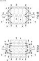
- FIGS. 5A and 5B are presented schematic views in section along a plane comprising the axial direction and orthogonal to the radial direction of a grid of a thrust reverser device for a turbomachine according to a second embodiment of the invention respectively in a position reverse thrust inactive and in a reverse thrust activated position.
- each rectangular zone 800 comprises two first movable partitions 82.
- the rectangular areas 800 could include a larger even number of first movable partitions 82.
- the grid 80 comprises a first and a second translation system 90 controlling the movement in the second direction D C of the two first movable partitions 82.
- the two translation systems 90 are coupled together to be actuated together in a synchronized manner. They are also synchronized with the thrust reverser device, to move the first movable partitions 82 into the first position when the thrust reverser device goes into an inactive mode, that is to say in an operating mode specific to the acoustic processing of the sound waves emitted by the turbomachine, or in the second position when the thrust reversal device goes into an active mode, that is to say in a thrust reversal operating mode.
- Each translation system 90 comprises connecting rods 92 and an actuator 94.
- Each connecting rod 92 comprises a first end 920 coupled in pivotal connection to one end, in the first direction D A , of a first movable partition 82.
- Each first partition 82 comprises, in the first direction D A , a first end 820 and a second end 825.
- the first end 920 of the connecting rods 92 of the first translation system 90 are connected in a pivoting connection to the first end 820 of the first partitions 82 movable and the first end 920 of the connecting rods 92 of the second translation system 90 are connected in a pivoting connection to the second end 825 of the first movable partitions 82.
- Each connecting rod 92 comprises a second end 925 opposite the first end 920.
- the second end 925 of each of the connecting rods 92 of a translation system 90 are mechanically connected together to make them integral with the actuator 94.
- each translation system 90 comprises two first and two second connecting rods 92.
- the second ends 925 of the two first connecting rods 92 are connected together in a first common pivoting connection 930, and the second ends 925 of the two second connecting rods 92 are connected together in one second common pivoting link 930.
- the two common pivoting links 930 are coupled to the actuator 94 via a connecting bar 928.
- the actuator 94 of the first translation system 90 and the actuator 94 of the second translation system 90 are coupled together, so that, when the actuators 94 are activated, following a request to switch to thrust reversal, each actuator 94 pushes the connecting bar 928 towards the frame 81 the grid 80, in other words the actuators 94 of the two translation systems 90 push the two connecting bars 928 towards each other.
- This action causes the deployment of the connecting rods 92, that is to say the distancing of the first ends 920 from each other of the connecting rods having their second end 925 connected together in the same common pivoting connection 930.
- This deployment of the connecting rods 92 cause the movement of each of the first two movable partitions 82 towards a fixed wall 810 or 815.
- each actuator 94 withdraws the connecting bar 928 in a direction opposite to the frame 81 the grid 80, in other words the actuators 94 of the two translation systems 90 move the two connecting bars 928 apart from each other.
- the invention thus provides a grid of a grid thrust reverser which allows, when the grid is mounted in a thrust reverser of a turbomachine, to redirect an air flow towards upstream of the turbomachine outside the nacelle, to minimize pressure losses through the grille and to maximize sound absorption efficiency.
Landscapes
- Engineering & Computer Science (AREA)
- Chemical & Material Sciences (AREA)
- Combustion & Propulsion (AREA)
- Mechanical Engineering (AREA)
- General Engineering & Computer Science (AREA)
- Aviation & Aerospace Engineering (AREA)
- Structures Of Non-Positive Displacement Pumps (AREA)
- Sliding-Contact Bearings (AREA)
- Connection Of Plates (AREA)
Description
L'invention concerne le traitement acoustique des ondes sonores émises par une turbomachine d'un aéronef, et plus particulièrement le traitement des ondes sonores au niveau des inverseurs de poussée de la turbomachine.The invention relates to the acoustic processing of sound waves emitted by a turbomachine of an aircraft, and more particularly the processing of sound waves at the level of the thrust reversers of the turbomachine.
Lorsqu'une turbomachine est en fonctionnement, l'interaction entre l'écoulement et les parties solides de la turbomachine sont responsables de la génération de bruits qui se propagent de part et d'autre de la turbomachine.When a turbomachine is in operation, the interaction between the flow and the solid parts of the turbomachine are responsible for the generation of noise which propagate on both sides of the turbomachine.
Un des moyens d'atténuer ce rayonnement acoustique est d'intégrer des moyens de traitement acoustique au niveau des surfaces en contacts avec les ondes sonores.One of the ways to attenuate this acoustic radiation is to integrate acoustic treatment means at the surfaces in contact with the sound waves.
Classiquement, le traitement acoustique d'un turboréacteur, et plus précisément du bruit rayonné par l'interaction entre le rotor et son environnement, est fait à l'aide de panneaux absorbants disposés au niveau des surfaces mouillées du conduit dans lequel se propagent les ondes sonores. On entend par surfaces mouillées, les surfaces en contact avec un écoulement fluide. Ces panneaux sont généralement des matériaux composites de type sandwich emprisonnant un nid d'abeille formant des cellules d'absorption acoustique.Conventionally, the acoustic treatment of a turbojet, and more precisely of the noise radiated by the interaction between the rotor and its environment, is carried out using absorbent panels placed at the level of the wetted surfaces of the conduit in which the waves propagate. sound. By wetted surfaces we mean surfaces in contact with a fluid flow. These panels are generally sandwich-type composite materials trapping a honeycomb forming sound absorption cells.
Il est connu par exemple dans l'état de la technique des panneaux acoustiques à un seul degré de liberté, ou SDOF pour « Single degree of freedom » en anglais, qui présentent une structure classique en nid d'abeilles de panneaux de traitement acoustique garnissant les parois de la nacelle d'une turbomachine.It is known for example in the state of the art acoustic panels with a single degree of freedom, or SDOF for “Single degree of freedom” in English, which have a classic honeycomb structure of acoustic treatment panels filling the walls of the nacelle of a turbomachine.
De par le principe de fonctionnement des technologies de panneau de traitement acoustique utilisant des cavités résonnantes, l'encombrement radial, c'est-à-dire l'épaisseur radiale, des panneaux de traitement acoustique dépend de la fréquence de traitement ciblée pour obtenir un maximum d'efficacité en termes d'atténuation acoustique.By the operating principle of acoustic treatment panel technologies using resonant cavities, the radial bulk, that is to say the radial thickness, of the acoustic treatment panels depends on the targeted treatment frequency to obtain a maximum efficiency in terms of sound attenuation.
Cependant, les architectures moteurs présentent de plus en plus des vitesses de rotation des roues à aubes de plus en plus lentes et un nombre d'aubes sur les roues à aubes de plus en plus petit, ce qui entraîne une baisse des fréquences dominantes du bruit associé au module comprenant la soufflante et l'étage redresseur, ou module « fan-OGV » en anglais pour « Outlet Guide Vane ». De ce fait, l'adéquation entre l'épaisseur optimale des panneaux acoustiques et l'encombrement disponible dans les nacelles n'est, actuellement, pas satisfaite. Pour ralentir un aéronef, une turbomachine comprend généralement des inverseur de poussée. Il existe principalement deux technologies d'inverseurs de poussée qui sont basées sur l'action d'une grille. On distingue deux types d'inverseurs de poussée à grille : les inverseurs de poussée à grille fixe et les inverseurs de poussée à grille en liaison glissière. Une grille selon l'art antérieur est divulguée dans le document
Sur les
La turbomachine 1 comprend une nacelle 2 à symétrie de révolution autour d'un axe X définissant une direction axiale DA, une direction radiale DR et une direction circonférentielle DC, une soufflante 3, une veine primaire 4, une veine secondaire, un étage redresseur primaire 5, un étage redresseur secondaire 6, et un dispositif 7 d'inversion de poussée à grille comportant une grille 8.The turbomachine 1 comprises a
Comme cela est illustrée sur les
Sur les
Comme cela est illustrée sur les
Les inverseurs de poussée représentent à la fois, un coût, une masse et un encombrement très pénalisants pour les performances de l'ensemble propulsif, alors qu'ils sont utilisés seulement à la fin de la phase d'atterrissage. Le volume qu'ils utilisent dans la nacelle ne peut notamment pas être utilisé, dans l'état de l'art, pour le traitement acoustique des ondes sonores émises par la turbomachine.Thrust reversers represent a cost, mass and bulk that are very detrimental to the performance of the propulsion unit, even though they are only used at the end of the landing phase. The volume that they use in the nacelle cannot in particular be used, in the state of the art, for the acoustic treatment of the sound waves emitted by the turbomachine.
Dans les architectures d'ensemble propulsif utilisant des inverseurs de poussée à portes qui se déploient à l'intérieur du flux secondaire pour dévier l'écoulement vers l'amont à l'extérieur de la nacelle, une pratique connue d'intégration de traitement acoustique classique consiste à intégrer des panneaux acoustiques dans des cavités des portes d'inverseur. Cette pratique consiste simplement à intégrer des panneaux absorbants classiques dans les volumes disponibles, comme cela est fait dans le carter fan.In propulsion assembly architectures using thrust reversers with doors which deploy inside the secondary flow to divert the flow upstream outside the nacelle, a known practice of integrating acoustic treatment classic consists of integrating acoustic panels into the cavities of the reverser doors. This practice simply consists of integrating classic absorbent panels into the available volumes, as is done in the fan housing.
L'invention vise à fournir une grille d'un inverseur de poussée à grille qui permette, lorsque la grille est montée dans un inverseur de poussée d'une turbomachine, à la fois de réorienter un flux d'air vers l'amont de la turbomachine à l'extérieur de la nacelle, de minimiser les pertes de charge à travers la grille et de maximiser l'efficacité d'absorption acoustique.The invention aims to provide a grid of a grid thrust reverser which allows, when the grid is mounted in a thrust reverser of a turbomachine, both to redirect an air flow upstream of the turbomachine outside the nacelle, to minimize pressure losses through the grid and to maximize sound absorption efficiency.
Un objet de l'invention propose une grille pour un dispositif d'inversion de poussée destiné à être monté sur une turbomachine d'un aéronef, la grille comprenant des premières cloisons s'étendant dans une première direction, des secondes cloisons fixes s'étendant dans une deuxième direction orthogonale à la première direction, et un cadre à l'intérieur duquel s'étendent les premières et secondes cloisons, le cadre comportant au moins deux parois fixes s'étendant selon dans la première direction, et au moins une partie de chaque première cloison s'étendant entre deux secondes cloisons dans un plan comprenant les première et deuxième directions.An object of the invention proposes a grid for a thrust reverser device intended to be mounted on a turbomachine of an aircraft, the grid comprising first partitions extending in a first direction, second fixed partitions extending in a second direction orthogonal to the first direction, and a frame inside which the first and second partitions extend, the frame comprising at least two fixed walls extending in the first direction, and at least a part of each first partition extending between two second partitions in a plane comprising the first and second directions.
Selon une caractéristique générale de l'invention, au moins une première cloison est mobile selon la seconde direction entre une première position dans laquelle ladite au moins une première cloison est distante, dans la seconde direction, desdites parois fixes du cadre pour former une pluralité de cavités résonnantes avec les premières cloisons et les parois fixes du cadre, et une seconde position dans laquelle ladite au moins une première cloison est en contact avec une paroi fixe ou autre première cloison.According to a general characteristic of the invention, at least one first partition is movable in the second direction between a first position in which said at least one first partition is distant, in the second direction, from said fixed walls of the frame to form a plurality of resonant cavities with the first partitions and the fixed walls of the frame, and a second position in which said at least one first partition is in contact with a fixed wall or other first partition.
En général, dans l'état de l'art, le nombre de cellules diffère grandement entre une grille d'inverseur et un panneau acoustique. Cette différence est due aux propriétés recherchées qui ne sont pas les mêmes.In general, in the state of the art, the number of cells differs greatly between an inverter grid and an acoustic panel. This difference is due to the desired properties which are not the same.
Une grille d'inverseur de poussée est habituellement caractérisée par une structure métallique, dimensionné de sorte à tenir la charge aérodynamique à laquelle elle est soumise en phase d'inversion de poussée. Cette structure génère également des pertes de charges. Une cellule est un volume constitué de quatre parois à travers lequel un fluide peut circuler. Disposer d'une densité de cellules trop importante peut nuire à l'efficacité de l'inverseur de poussée du fait d'une résistante trop forte au passage de l'air.A thrust reverser grille is usually characterized by a metallic structure, dimensioned so as to withstand the aerodynamic load to which it is subjected during the thrust reversal phase. This structure also generates pressure losses. A cell is a volume made up of four walls through which a fluid can flow. Having too high a density of cells can harm the effectiveness of the thrust reverser due to excessive resistance to the passage of air.
De l'autre côté, les structures de panneaux acoustiques ne subissent pas d'effort aérodynamique. Les cloisons qui les constituent sont très fines et leur faible volume permet d'optimiser la fréquence d'accord du panneau, c'est-à-dire la fréquence d'atténuation maximale.On the other hand, acoustic panel structures do not undergo aerodynamic stress. The partitions which constitute them are very thin and their small volume makes it possible to optimize the tuning frequency of the panel, that is to say the maximum attenuation frequency.
Les deux fonctions d'inversion de poussée et de traitement acoustique font donc appel à des structures de cellule très différentes.The two functions of thrust reversal and acoustic processing therefore use very different cell structures.
Les secondes cloisons sont destinées à être orientées selon une direction orthogonale à la direction d'écoulement d'un flux gazeux à l'intérieur d'une turbomachine comportant un dispositif d'inversion de poussée doté d'une telle grille. Lorsque la grille est montée sur un dispositif d'inversion de poussée sur une turbomachine, les secondes cloisons, orientées selon une direction azimutale ou radiale de la turbomachine, sont indispensables pour garantir la fonctionnalité d'inversion de poussée. C'est en effet grâce à ces secondes cloisons que le flux d'air circulant dans une veine, à l'intérieur de la nacelle dans laquelle le dispositif d'inversion de poussée est monté, peut être capté et réorienté vers l'amont de la turbomachine, par rapport au sens d'écoulement du flux à l'intérieur de la nacelle, à l'extérieur de la nacelle.The second partitions are intended to be oriented in a direction orthogonal to the direction of flow of a gas flow inside a turbomachine comprising a thrust reversal device equipped with such a grid. When the grid is mounted on a thrust reversal device on a turbomachine, the second partitions, oriented in an azimuthal or radial direction of the turbomachine, are essential to guarantee the thrust reversal functionality. It is in fact thanks to these second partitions that the air flow circulating in a vein, inside the nacelle in which the thrust reversal device is mounted, can be captured and reoriented upstream of the turbomachine, relative to the direction of flow of the flow inside of the nacelle, outside the nacelle.
Les premières cloisons sont destinées à être orientées selon la direction du flux gazeux à l'intérieur d'une turbomachine comportant un dispositif d'inversion de poussée doté d'une telle grille. Lorsque la grille est montée sur un dispositif d'inversion de poussée sur une turbomachine, les premières cloisons, orientées selon une direction axiale de la turbomachine, ne sont pas indispensables pour la fonctionnalité d'inversion de poussée. En revanche, elles permettent la formation de cavités résonnantes permettant d'atténuer des ondes acoustiques générées par la turbomachine.The first partitions are intended to be oriented according to the direction of the gas flow inside a turbomachine comprising a thrust reversal device equipped with such a grid. When the grid is mounted on a thrust reversal device on a turbomachine, the first partitions, oriented in an axial direction of the turbomachine, are not essential for the thrust reversal functionality. On the other hand, they allow the formation of resonant cavities making it possible to attenuate acoustic waves generated by the turbomachine.
La mobilité selon la seconde direction d'au moins une première cloison de la grille selon l'invention offre la possibilité de modifier le nombre de cellules de la grille en fonction du mode de fonctionnement de la grille, pour avoir par exemple, pour un même volume donné compris dans la première direction entre deux secondes cloisons ou une seconde cloison et le cadre, une seule grande cellule ou bien au moins deux cellules plus petites en fonction du nombre de secondes cloisons mobiles. Autrement dit, la mobilité d'au moins une première cloison permet de faire varier le nombre de cellules pour limiter ce nombre en mode « inversion de poussée », et augmenter ce nombre en mode « traitement acoustique ».The mobility in the second direction of at least a first partition of the grid according to the invention offers the possibility of modifying the number of cells of the grid depending on the mode of operation of the grid, to have for example, for the same given volume included in the first direction between two second partitions or a second partition and the frame, a single large cell or at least two smaller cells depending on the number of second movable partitions. In other words, the mobility of at least a first partition makes it possible to vary the number of cells to limit this number in “thrust reversal” mode, and increase this number in “acoustic treatment” mode.
Dans un premier aspect de la grille, chaque première cloison mobile peut comprendre des encoches conformées pour accueillir une seconde cloison et permettre le déplacement de ladite première cloison le long des secondes cloisons, et chaque encoche peut comprendre un joint permettant d'étanchéifier l'encoche.In a first aspect of the grid, each first movable partition can comprise notches shaped to accommodate a second partition and allow said first partition to move along the second partitions, and each notch can comprise a seal making it possible to seal the notch .
Cette conformation permet d'améliorer la formation des cellules en cavités résonnantes lorsque la grille fonctionne en mode traitement acoustique en limitant les fuites acoustiques entre les cellules.This conformation makes it possible to improve the formation of cells in resonant cavities when the grid operates in acoustic treatment mode by limiting acoustic leaks between cells.
Dans un deuxième aspect de la grille, les joints des encoches peuvent être des joints à brosses ou à languettes.In a second aspect of the grid, the joints of the notches can be brush or tongue joints.
Dans un troisième aspect de la grille, la grille peut comprendre au moins deux premières cloisons mobiles et au moins un système de translation de premières cloisons comportant un actionneur et au moins deux bielles comportant une première et une seconde extrémités, les secondes extrémités des bielles d'un même système de translation étant raccordées ensemble pour former une liaison pivot commune raccordée à l'actionneur, et la première extrémité de chaque bielle d'un même système de translation étant fixée en liaison pivotante à une première cloison mobile.In a third aspect of the grid, the grid can comprise at least two first movable partitions and at least one first translation system. partitions comprising an actuator and at least two connecting rods comprising a first and a second end, the second ends of the connecting rods of the same translation system being connected together to form a common pivot connection connected to the actuator, and the first end of each connecting rod of the same translation system being fixed in pivotal connection to a first movable partition.
L'utilisation d'un même actionneur permet de minimiser le nombre d'actionneur nécessaire pour réaliser la fonction souhaitée.The use of the same actuator makes it possible to minimize the number of actuators necessary to achieve the desired function.
Dans un quatrième aspect de la grille, la grille peut comprendre au moins une paire de systèmes de translation de premières cloisons, les systèmes de translation d'une même paire de systèmes étant raccordés aux mêmes premières cloisons mobiles.In a fourth aspect of the grid, the grid may comprise at least one pair of translation systems of first partitions, the translation systems of the same pair of systems being connected to the same first movable partitions.
L'utilisation de deux systèmes de translation pour déplacer une même ou les mêmes premières cloisons mobiles permet d'avoir deux points de fixation sur les premières cloisons mobiles et ainsi de réduire les contraintes mécaniques imposées sur un même point de fixation et de réduire les déformations des premières cloisons mobiles lors des translations.The use of two translation systems to move the same or the same first movable partitions makes it possible to have two fixing points on the first movable partitions and thus to reduce the mechanical constraints imposed on the same fixing point and to reduce deformations. of the first movable partitions during translations.
Dans un cinquième aspect de la grille, ladite au moins une première cloison mobile peut comprendre, selon la première direction, une première et une seconde extrémités, les premières extrémités des bielles d'un premier système d'une paire de systèmes étant fixées en liaison pivotante aux premières extrémités de premières cloisons mobiles et les premières extrémités des bielles d'un second système de la même paire de systèmes étant fixées en liaison pivotante aux secondes extrémités des mêmes premières cloisons mobiles.In a fifth aspect of the grid, said at least one first movable partition may comprise, in the first direction, a first and a second end, the first ends of the connecting rods of a first system of a pair of systems being fixed in connection pivoting at the first ends of first movable partitions and the first ends of the connecting rods of a second system of the same pair of systems being fixed in pivotal connection to the second ends of the same first movable partitions.
Le raccordement des systèmes de translation d'une même paire de systèmes aux deux extrémités des premières cloisons mobiles de la grille permet de faciliter les translations, en minimisant les contraintes de flexion dans les cloisons mobiles.The connection of the translation systems of the same pair of systems at the two ends of the first movable partitions of the grid makes it possible to facilitate translations, by minimizing the bending stresses in the movable partitions.
Dans un sixième aspect de la grille, les actionneurs des systèmes de translation d'une même paire de systèmes de translation peuvent être mécaniquement raccordés ensemble.In a sixth aspect of the grid, the actuators of the translation systems of the same pair of translation systems can be mechanically connected together.
Le raccordement des actionneurs des systèmes de translation d'une même paire de systèmes de translation permet d'obtenir une synchronisation précise des contraintes de flexion dans les premières cloisons mobiles et des efforts de frottement.Connecting the actuators of the translation systems of the same pair of translation systems makes it possible to obtain precise synchronization of the bending stresses in the first movable partitions and friction forces.
Dans un septième aspect de la grille, les bielles raccordées à des premières cloisons disposées entre deux parois fixes successivement disposées dans la seconde direction ont une longueur comprise entre une demie fois et une fois la distance séparant lesdites deux parois fixes successives.In a seventh aspect of the grid, the connecting rods connected to first partitions arranged between two fixed walls successively arranged in the second direction have a length of between half a time and one time the distance separating said two successive fixed walls.
Dans un huitième aspect de la grille, plus de deux premières cloisons mobiles sont disposées entre deux parois fixes successivement disposées dans la seconde direction, et les bielles raccordées à des premières cloisons disposées entre lesdites deux parois fixes successives ont des longueurs différentes les unes des autres.In an eighth aspect of the grid, more than two first movable partitions are arranged between two fixed walls successively arranged in the second direction, and the connecting rods connected to first partitions arranged between said two successive fixed walls have different lengths from each other. .
Dans un neuvième aspect de la grille, l'actionneur dudit au moins un système de translation peut être un actionneur pneumatique ou électrique configuré pour écarter les premières cloisons mobiles l'une de l'autre jusqu'à la première position ou les rapprocher l'une de l'autre jusqu'à la seconde position.In a ninth aspect of the grid, the actuator of said at least one translation system can be a pneumatic or electric actuator configured to move the first movable partitions apart from each other up to the first position or bring them closer together. one from the other to the second position.
Dans une dixième aspect de la grille, l'épaisseur des premières cloisons peut être comprise entre 0,5 mm et 4 mm pour être les plus fines possible pour minimiser la masse et les pertes de charge dans la grille. L'épaisseur des premières cloisons est mesurée selon la seconde direction.In a tenth aspect of the grid, the thickness of the first partitions can be between 0.5 mm and 4 mm to be as thin as possible to minimize the mass and the pressure losses in the grid. The thickness of the first partitions is measured in the second direction.
Dans un onzième aspect de la grille, la grille peut comprendre des butées positionnées sur la grille pour arrêter la translation des premières cloisons mobiles dans la première position pour obtenir un positionnement précis.In an eleventh aspect of the grid, the grid may include stops positioned on the grid to stop the translation of the first movable partitions in the first position to obtain precise positioning.
Dans un autre objet de l'invention, il est proposé un dispositif d'inversion de poussée à grille pour une turbomachine d'un aéronef, caractérisé en ce qu'il comprend au moins une grille telle que définie ci-dessus.In another object of the invention, there is proposed a grid thrust reversal device for a turbomachine of an aircraft, characterized in that it comprises at least one grid as defined above.
Dans un premier aspect du dispositif d'inversion de poussée, l'actionneur dudit au moins un système de translation est configuré pour écarter les premières cloisons mobiles l'une de l'autre jusqu'à la première position ou les rapprocher l'une de l'autre jusqu'à la seconde position de manière synchronisée avec le déclenchement du dispositif d'inversion de poussée.In a first aspect of the thrust reverser device, the actuator of said at least one translation system is configured to move the first movable partitions apart from each other up to the first position or bring them closer together. the other up to the second position synchronously with the triggering of the thrust reverser device.
La synchronisation de l'actionneur avec le déclenchement du dispositif d'inversion de poussée permet d'exercer un effort de translation sur l'ensemble des points de liaison permettant de déployer ou de replier la structure de cloisons mobile en fonction du mode de fonctionnement du dispositif d'inversion de poussée, le dispositif d'inversion de poussée pouvant être inactif, c'est-à-dire dans un mode de traitement acoustique, ou actif, c'est-à-dire dans un mode d'inversion de poussée.The synchronization of the actuator with the triggering of the thrust reversal device makes it possible to exert a translation force on all the points of connection allowing the mobile partition structure to be deployed or folded depending on the operating mode of the thrust reverser device, the thrust reverser device being able to be inactive, that is to say in an acoustic treatment mode , or active, that is to say in a thrust reversal mode.
Dans encore un autre objet de l'invention, il est proposé une turbomachine destinée à être montée sur un aéronef, la turbomachine comprenant une nacelle à symétrie de révolution définissant une direction axiale et une direction radiale, la nacelle comportant une épaisseur selon la direction radiale et un logement s'étendant selon la direction axiale dans son épaisseur pour recevoir une grille d'un dispositif d'inversion de poussée à grille.In yet another object of the invention, there is proposed a turbomachine intended to be mounted on an aircraft, the turbomachine comprising a nacelle with symmetry of revolution defining an axial direction and a radial direction, the nacelle comprising a thickness in the radial direction and a housing extending in the axial direction in its thickness for receiving a gate of a gate thrust reverser device.
Selon une caractéristique générale de cet objet de l'invention, la turbomachine peut comprendre un dispositif d'inversion de poussée à grille tel que défini ci-dessus, la grille étant disposée, lorsque l'inversion de poussée n'est pas requise, dans le logement correspondant de la nacelle de la turbomachine avec les première cloisons s'étendant selon la direction axiale et la direction radiale et les secondes cloisons s'étendant selon la direction radiale et selon une direction orthogonale à la direction axiale et à la direction radiale, la première direction correspondant à la direction axiale.According to a general characteristic of this object of the invention, the turbomachine can comprise a grid thrust reversal device as defined above, the grid being arranged, when thrust reversal is not required, in the corresponding housing of the nacelle of the turbomachine with the first partitions extending in the axial direction and the radial direction and the second partitions extending in the radial direction and in a direction orthogonal to the axial direction and the radial direction, the first direction corresponding to the axial direction.
Dans un mode de réalisation de la turbomachine, la nacelle peut comprendre une paroi perforée formant une paroi radialement interne du logement et une paroi réfléchissante formant une paroi radialement externe du logement.In one embodiment of the turbomachine, the nacelle may comprise a perforated wall forming a radially internal wall of the housing and a reflecting wall forming a radially external wall of the housing.
Dans un autre objet de l'invention, il est proposé un aéronef comprenant au moins une turbomachine telle que définie ci-dessus.In another object of the invention, an aircraft is proposed comprising at least one turbomachine as defined above.
-
[
Fig. 1A-1B ] Lesfigures 1A et 1B , déjà décrites, présentent des vues schématiques en section dans un plan longitudinal d'une turbomachine selon un premier mode de réalisation connu de l'état de la technique respectivement dans une position d'inversion de poussée inactive et dans une position d'inversion de poussée activée.[Fig. 1A-1B ] THEFigures 1A and 1B , already described, present schematic sectional views in a longitudinal plane of a turbomachine according to a first embodiment known from the state of the art respectively in an inactive thrust reversal position and in a thrust reversal position. thrust activated. -
[
Fig. 2A-2B ] Lesfigures 2A et 2B , déjà décrites, présentent des vues schématiques en section dans un plan longitudinal d'une turbomachine selon un second mode de réalisation connu de l'état de la technique respectivement dans une position d'inversion de poussée inactive et dans une position d'inversion de poussée activée.[Fig. 2A-2B ] THEFigures 2A and 2B , already described, present schematic sectional views in a longitudinal plane of a turbomachine according to a second mode of known embodiment of the state of the art respectively in an inactive thrust reversal position and in an activated thrust reversal position. -
[
Fig. 3A-3B ] Lesfigures 3A et 3B présentent des vues schématiques en section selon un plan comprenant la direction axiale et orthogonale à la direction radiale d'une grille d'un dispositif d'inversion de poussée pour une turbomachine selon un premier mode de réalisation de l'invention respectivement dans une position d'inversion de poussée inactive et dans une position d'inversion de poussée activé.[Fig. 3A-3B ] THEFigures 3A and 3B present schematic views in section along a plane comprising the axial direction and orthogonal to the radial direction of a grid of a thrust reverser device for a turbomachine according to a first embodiment of the invention respectively in a position of reverse thrust inactive and in a reverse thrust activated position. -
[
Fig. 4 ] Lafigure 4 présente une vue schématique en section selon un plan comprenant la direction axiale et la direction radiale d'une grille d'un dispositif d'inversion de poussée pour une turbomachine selon un mode de réalisation de l'invention.[Fig. 4 ] Therefigure 4 presents a schematic sectional view along a plane comprising the axial direction and the radial direction of a grid of a thrust reversal device for a turbomachine according to one embodiment of the invention. -
[
fig. 5A-5B ] Lesfigures 5A et 5B présentent des vues schématiques en section selon un plan comprenant la direction axiale et orthogonale à la direction radiale d'une grille d'un dispositif d'inversion de poussée pour une turbomachine selon un second mode de réalisation de l'invention respectivement dans une position d'inversion de poussée inactive et dans une position d'inversion de poussée activé.[fig. 5A-5B ] THEFigures 5A and 5B present schematic views in section along a plane comprising the axial direction and orthogonal to the radial direction of a grid of a thrust reverser device for a turbomachine according to a second embodiment of the invention respectively in a position of reverse thrust inactive and in a reverse thrust activated position.
Sur les
La turbomachine comprend un dispositif d'inversion de poussée pouvant fonctionner selon le fonctionnement décrit sur les
Le dispositif d'inversion de poussée comprend une pluralité de grilles 80 assemblées pour former une couronne grillagée. Chaque grille 80 comprend un cadre 81 à l'intérieur duquel s'étendent des premières cloisons 82 dans une première direction et des secondes cloisons 83 dans une deuxième direction orthogonale à la première direction.The thrust reversal device comprises a plurality of
En outre, comme illustré sur les
Comme cela est illustré sur la
Comme cela est également illustré sur la
L'épaisseur des premières cloisons 83 est comprise entre 0,5 mm et 4 mm pour être les plus fines possible pour minimiser la masse et les pertes de charge dans la grille.The thickness of the
Lorsque le dispositif d'inversion de poussée est monté sur une turbomachine telles que celles illustrées sur les
Les secondes cloisons 83 sont des cloisons azimutales destinées à orienter le flux gazeux F vers l'extérieur de la nacelle 2 et en amont de la turbomachine 1 pour l'inversion de poussée lorsque le dispositif d'inversion de poussée est activée. Les premières cloisons 82 sont des cloisons axiales destinées à définir, avec les secondes cloisons 83, des cavités résonnantes 84 pour l'absorption des ondes acoustiques générées par la turbomachine, lorsque le dispositif d'inversion de poussée est inactif.The
Comme cela est illustré sur les
Sur l'exemple illustré sur les
La
Sur les
Dans ce mode de réalisation, chaque zone rectangulaire 800 comprend deux premières cloisons 82 mobiles. Les zones rectangulaires 800 pourraient comprendre un nombre paire plus grand de premières cloisons 82 mobiles.In this embodiment, each
Dans le second mode de réalisation illustré sur les
Chaque système de translation 90 comprend des bielles 92 et un actionneur 94. Chaque bielle 92 comprend une première extrémité 920 couplée en liaison pivotante à une extrémité, selon la première direction DA, d'une première cloison 82 mobile. Chaque première cloison 82 comprend, dans la première direction DA, une première extrémité 820 et une seconde extrémité 825. La première extrémité 920 des bielles 92 du premier système de translation 90 sont raccordées en liaison pivotante à la première extrémité 820 des premières cloisons 82 mobiles et la première extrémité 920 des bielles 92 du second système de translation 90 sont raccordées en liaison pivotante à la seconde extrémité 825 des premières cloisons 82 mobiles.Each
Chaque bielle 92 comprend une seconde extrémité 925 opposée à la première extrémité 920. La seconde extrémité 925 de chacune des bielles 92 d'un système de translation 90 sont mécaniquement raccordées ensemble pour les rendre solidaire de l'actionneur 94.Each connecting
Dans l'exemple illustré sur les
L'actionneur 94 du premier système de translation 90 et l'actionneur 94 du second système de translation 90 sont couplés ensemble, si bien que, lorsque les actionneurs 94 sont activés, suite à une requête de passage en inversion de poussée, chaque actionneur 94 pousse la barre de liaison 928 vers le cadre 81 la grille 80, autrement dit les actionneurs 94 des deux systèmes de translation 90 poussent les deux barres de liaison 928 l'une vers l'autre.The
Cette action entraîne le déploiement des bielles 92, c'est-à-dire l'éloignement des premières extrémités 920 l'une de l'autre des bielles ayant leur seconde extrémité 925 raccordées ensemble en une même liaison pivotante commune 930. Ce déploiement des bielles 92 entraînent le déplacement de chacune des deux premières cloisons mobiles 82 vers une paroi fixe 810 ou 815.This action causes the deployment of the connecting
Lorsque les actionneurs 94 sont désactivés, suite à une requête de fin d'inversion de poussée, chaque actionneur 94 retire la barre de liaison 928 dans une direction opposée au cadre 81 la grille 80, autrement dit les actionneurs 94 des deux systèmes de translation 90 écartent les deux barres de liaison 928 l'une de l'autre.When the
Cette action entraîne la contraction des bielles 92, c'est-à-dire le rapprochement des premières extrémités 920 l'une de l'autre des bielles ayant leur seconde extrémité 925 raccordées ensemble en une même liaison pivotante commune 930. Ce rapprochement des bielles 92 entraînent l'éloignement de chacune des deux premières cloisons mobiles 82 des parois fixe 810 ou 815 jusqu'à former, avec les secondes cloisons 83 des cavités résonnantes de même volume.This action results in the contraction of the connecting
L'invention fournit ainsi une grille d'un inverseur de poussée à grille qui permette, lorsque la grille est montée dans un inverseur de poussée d'une turbomachine, à la fois de réorienter un flux d'air vers l'amont de la turbomachine à l'extérieur de la nacelle, de minimiser les pertes de charge à travers la grille et de maximiser l'efficacité d'absorption acoustique.The invention thus provides a grid of a grid thrust reverser which allows, when the grid is mounted in a thrust reverser of a turbomachine, to redirect an air flow towards upstream of the turbomachine outside the nacelle, to minimize pressure losses through the grille and to maximize sound absorption efficiency.
Claims (17)
- A cascade (80) for a thrust reversal device intended to be mounted on a turbomachine of an aircraft, the cascade (80) comprising first partitions (82) extending in a first direction (DA), second fixed partitions (83) extending in a second direction (DC) orthogonal to the first direction (DA), and a frame (81) inside which the first and second partitions extend (82, 83), the frame (81) comprising at least two fixed walls (810, 815) extending according to the first direction (DA), and at least one part of each first partition (82) extending between two second partitions (83) in a plane comprising the first and second directions (DA, DC),
wherein at least one first partition (82) is mobile according to the second direction (DC) between a first position in which said at least one first partition (82) is distant, in the second direction (DC), from said fixed walls (810, 815) of the frame (81) to form a plurality of resonating cavities (84) with the first partitions (83) and/or the fixed walls (810, 815) of the frame (81), and a second position in which said at least one first partition (82) is in contact with a fixed wall (810, 815) of the frame (81) or another first partition (82). - The cascade (80) according to claim 1, wherein each first mobile partition (82) comprises notches (820) configured to house a second partition (83) and allow said first partition (82) to move along the second partitions (83), and each notch (820) comprises a seal (825) for sealing the notch (820).
- The cascade (80) according to claim 2, wherein the seals (825) of the notches (820) are brush seals or tongue seals.
- The cascade (80) according to any one of claims 1 to 3, also comprising at least two first mobile partitions (82) and at least one translation system (90) of first partitions (82) comprising an actuator (94) and at least two tie rods (92) comprising a first and second ends (920, 925), the second ends (925) of the tie rods (92) of the same translation system (90) being connected together via at least one common pivot link (930) connected to the actuator (94), and the first end (920) of each tie rod (92) of the same translation system (90) being fixed as a pivoting link to a first mobile partition (82).
- The cascade (80) according to claim 4, also comprising at least one pair of translation systems (90) of first partitions (82), the translation systems (90) of the same pair of systems being connected to the same first mobile partitions (82).
- The cascade (80) according to claim 5, wherein said at least one first mobile partition (2) comprises, according to the first direction (DA), a first and second ends (820, 825), the first ends (920) of the tie rods (92) of a first translation system (90) of a pair of translation systems being fixed as a pivoting link to the first ends (820) of first mobile partitions (82) and the first ends (920) of the tie rods (92) of a second translation system (90) of the same pair of translation systems being fixed as a pivoting link to the second ends (825) of the same first mobile partitions (82).
- The cascade (80) according to any one of claims 5 or 6, wherein the actuators (94) of the translation systems (90) of the same pair of translation systems are connected together mechanically.
- The cascade (80) according to any one of claims 4 to 7, wherein the tie rods (92) connected to first partitions (82) arranged between two fixed walls (810, 815) successively arranged in the second direction (DC) have a length between a half and all the distance separating said two successive fixed walls (810, 815).
- The cascade (80) according to any one of claims 4 to 8, wherein more than two first mobile partitions (82) are arranged between two fixed walls (810, 815) successively arranged in the second direction (DC), and the tie rods (92) connected to first partitions (82) arranged between said two successive fixed walls (810, 815) have lengths different to each other.
- The cascade according to any one of claims 4 to 9, wherein the actuator (94) of the at least one translation system (90) is a pneumatic or electrical actuator configured to move the first mobile partitions (82) away from each other as far as the first position or move them more closely to each other as far as the second position.
- The cascade (80) according to any one of claims 1 to 10, wherein the thickness of the first partitions (82) is between 0.5 mm and 4 mm, the thickness of the first partitions (82) being measured according to the second direction (DC).
- The cascade according to any one of claims 1 to 11, also comprising stops positioned on the cascade (80) for stopping the translation of the first mobile partitions (82) in the first position.
- A cascade thrust reversal device for a turbomachine of an aircraft, characterised in that it comprises at least one cascade (80) according to any one of claims 1 to 12.
- A thrust reversal cascade device according to claim 13, wherein the actuator (94) of said at least one translation system (90) is configured to move the first mobile partitions (82) away from each other as far as the first position or move them more closely to each other as far as the second position in a synchronised manner with triggering of the thrust reversal device.
- A turbomachine (1) intended to be mounted on an aircraft, the turbomachine (1) comprising a nacelle (2) in rotational symmetry defining an axial direction (DA) and a radial direction (DR), the nacelle (2) comprising a thickness according to the radial direction (DR) and a housing (25) extending according to the axial direction (DA) in its thickness for receiving a cascade (80) of a thrust reversal cascade device,
characterised in that it comprises a thrust reversal cascade device according to claim 13, the cascade (80) being arranged, when the thrust reversal is not required, in the corresponding housing (25) of the nacelle (2) of the turbomachine (1) with the first partitions (82) extending according to the axial direction (DA) and the radial direction (DR) and the second partitions (83) extending according to the radial direction (DR) and according to a direction orthogonal to the axial direction (DA) and to the radial direction (DR), the first direction corresponding to the axial direction (DA). - The turbomachine (1) according to claim 15, wherein the nacelle (2) comprises a perforated wall (254) forming a radially internal wall of the housing (25) and a reflecting wall (256) forming a radially external wall of the housing (25).
- An aircraft comprising at least one turbomachine (1) according to any one of claims 15 or 16.
Applications Claiming Priority (2)
| Application Number | Priority Date | Filing Date | Title |
|---|---|---|---|
| FR1904654A FR3095676B1 (en) | 2019-05-03 | 2019-05-03 | Thrust reverser grille including acoustic treatment |
| PCT/EP2020/059560 WO2020224887A1 (en) | 2019-05-03 | 2020-04-03 | Thrust reverser cascade including an acoustic treatment |
Publications (2)
| Publication Number | Publication Date |
|---|---|
| EP3963198A1 EP3963198A1 (en) | 2022-03-09 |
| EP3963198B1 true EP3963198B1 (en) | 2023-11-08 |
Family
ID=67957014
Family Applications (1)
| Application Number | Title | Priority Date | Filing Date |
|---|---|---|---|
| EP20715881.7A Active EP3963198B1 (en) | 2019-05-03 | 2020-04-03 | Thrust reverser cascade including an acoustic treatment |
Country Status (8)
| Country | Link |
|---|---|
| US (1) | US11788489B2 (en) |
| EP (1) | EP3963198B1 (en) |
| JP (1) | JP7475369B2 (en) |
| CN (1) | CN113950574B (en) |
| BR (1) | BR112021021887A2 (en) |
| CA (1) | CA3136094A1 (en) |
| FR (1) | FR3095676B1 (en) |
| WO (1) | WO2020224887A1 (en) |
Families Citing this family (1)
| Publication number | Priority date | Publication date | Assignee | Title |
|---|---|---|---|---|
| FR3136517A1 (en) * | 2022-06-14 | 2023-12-15 | Airbus Operations | Aircraft engine nacelle provided with a thrust reverser with a movable ejection structure. |
Family Cites Families (8)
| Publication number | Priority date | Publication date | Assignee | Title |
|---|---|---|---|---|
| US5706649A (en) * | 1995-04-03 | 1998-01-13 | Boeing North American, Inc. | Multi axis thrust vectoring for turbo fan engines |
| FR2786532B1 (en) * | 1998-11-26 | 2001-09-07 | Snecma | OVERHEAD GRID TURBOREACTOR DRIVE INVERTER |
| JP2009062977A (en) | 2007-08-15 | 2009-03-26 | Rohr Inc | Linear acoustic liner |
| FR2947869B1 (en) * | 2009-07-10 | 2011-12-09 | Snecma | EXTENDABLE FINS GRID FOR AN AIRCRAFT TURBOMACHINE PUSH INVERSION SYSTEM |
| FR2960918B1 (en) | 2010-06-08 | 2012-05-25 | Aircelle Sa | AUTOSUPPORTE TYPE DEVIATION GRID FOR PUSH INVERTER |
| US9835112B2 (en) | 2014-02-10 | 2017-12-05 | MRA Systems Inc. | Thrust reverser cascade |
| FR3027065B1 (en) * | 2014-10-13 | 2016-12-23 | Snecma | DEPLOYABLE GRID WITH FINS FOR AN AIRCRAFT TURBOMACHINE PUSH INVERSION SYSTEM |
| US10533521B2 (en) * | 2017-07-31 | 2020-01-14 | The Boeing Company | Inflatable cascade assembly, system, and method for a cascade thrust reverser system |
-
2019
- 2019-05-03 FR FR1904654A patent/FR3095676B1/en active Active
-
2020
- 2020-04-03 EP EP20715881.7A patent/EP3963198B1/en active Active
- 2020-04-03 CN CN202080043304.XA patent/CN113950574B/en active Active
- 2020-04-03 US US17/608,265 patent/US11788489B2/en active Active
- 2020-04-03 WO PCT/EP2020/059560 patent/WO2020224887A1/en unknown
- 2020-04-03 CA CA3136094A patent/CA3136094A1/en active Pending
- 2020-04-03 JP JP2021564989A patent/JP7475369B2/en active Active
- 2020-04-03 BR BR112021021887A patent/BR112021021887A2/en unknown
Also Published As
| Publication number | Publication date |
|---|---|
| FR3095676A1 (en) | 2020-11-06 |
| BR112021021887A2 (en) | 2021-12-28 |
| EP3963198A1 (en) | 2022-03-09 |
| CN113950574A (en) | 2022-01-18 |
| JP7475369B2 (en) | 2024-04-26 |
| WO2020224887A1 (en) | 2020-11-12 |
| US20220325680A1 (en) | 2022-10-13 |
| JP2022530566A (en) | 2022-06-29 |
| CN113950574B (en) | 2022-10-28 |
| CA3136094A1 (en) | 2020-11-12 |
| US11788489B2 (en) | 2023-10-17 |
| FR3095676B1 (en) | 2021-04-09 |
Similar Documents
| Publication | Publication Date | Title |
|---|---|---|
| WO2017021628A1 (en) | Acoustic attenuation structure with a plurality of attenuation degrees for a propulsion assembly of an aircraft | |
| EP3963199B1 (en) | Thrust reverser cascade including acoustic treatment | |
| FR3067406B1 (en) | THRUST INVERTER SYSTEM HAVING LIMITED AERODYNAMIC DISTURBANCES | |
| EP3850616B1 (en) | Acoustic treatment panel for a turbojet engine | |
| EP2334557A1 (en) | Device for connecting an air inlet with an aircraft nacelle actuator assembly | |
| EP0289376A1 (en) | Acoustic panel for sound-proof lining, and turbo jet engine comprising such a lining | |
| EP3963198B1 (en) | Thrust reverser cascade including an acoustic treatment | |
| FR2934875A1 (en) | NACELLE OF TURBOREACTEUR MOBILE CHEVRONS. | |
| EP3963200B1 (en) | Thrust reverser cascade including acoustic treatment | |
| WO2022129778A1 (en) | Reduced bulk acoustic treatment panel for a turbojet engine | |
| WO2011073558A1 (en) | Reverse thrust device | |
| EP1092859A1 (en) | Thrust reverser for a turbojet-engine | |
| EP3963197B1 (en) | Thrust reverser cascade including an acoustic treatment | |
| WO2019092383A1 (en) | Thrust reverser for an aircraft turbojet engine nacelle and associated nacelle | |
| EP3719293A1 (en) | Turbojet engine comprising a nacelle provided with an inverter system and a mobile cascade grid | |
| FR3065754B1 (en) | ACOUSTIC ABSORPTION CELL FOR TURBOJETACTOR AND ASSOCIATED ACOUSTIC TREATMENT PANEL | |
| CA2761601C (en) | Turbine engine comprising an exhaust-gas guide cone with a sound suppressor | |
| EP4066235B1 (en) | Resonating patch and acoustic treatment cell provided with such a patch | |
| FR3130327A1 (en) | Thrust reverser at the door of an aircraft turbojet nacelle with a device for deflecting the fluids outwards | |
| FR3027066A1 (en) | THRUST INVERTER FOR AN AIRCRAFT AIRCRAFT TANK AND NACELLE | |
| EP4293215A1 (en) | Aircraft engine nacelle provided with a thrust reverser with a mobile ejection structure | |
| FR3121713A1 (en) | Thrust reverser with mobile grids comprising a multifunctional fixed structure | |
| FR3096741A1 (en) | Aircraft propulsion system |
Legal Events
| Date | Code | Title | Description |
|---|---|---|---|
| STAA | Information on the status of an ep patent application or granted ep patent |
Free format text: STATUS: UNKNOWN |
|
| STAA | Information on the status of an ep patent application or granted ep patent |
Free format text: STATUS: THE INTERNATIONAL PUBLICATION HAS BEEN MADE |
|
| STAA | Information on the status of an ep patent application or granted ep patent |
Free format text: STATUS: THE INTERNATIONAL PUBLICATION HAS BEEN MADE |
|
| PUAI | Public reference made under article 153(3) epc to a published international application that has entered the european phase |
Free format text: ORIGINAL CODE: 0009012 |
|
| STAA | Information on the status of an ep patent application or granted ep patent |
Free format text: STATUS: REQUEST FOR EXAMINATION WAS MADE |
|
| 17P | Request for examination filed |
Effective date: 20211129 |
|
| AK | Designated contracting states |
Kind code of ref document: A1 Designated state(s): AL AT BE BG CH CY CZ DE DK EE ES FI FR GB GR HR HU IE IS IT LI LT LU LV MC MK MT NL NO PL PT RO RS SE SI SK SM TR |
|
| DAV | Request for validation of the european patent (deleted) | ||
| DAX | Request for extension of the european patent (deleted) | ||
| GRAP | Despatch of communication of intention to grant a patent |
Free format text: ORIGINAL CODE: EPIDOSNIGR1 |
|
| STAA | Information on the status of an ep patent application or granted ep patent |
Free format text: STATUS: GRANT OF PATENT IS INTENDED |
|
| INTG | Intention to grant announced |
Effective date: 20221213 |
|
| GRAS | Grant fee paid |
Free format text: ORIGINAL CODE: EPIDOSNIGR3 |
|
| GRAJ | Information related to disapproval of communication of intention to grant by the applicant or resumption of examination proceedings by the epo deleted |
Free format text: ORIGINAL CODE: EPIDOSDIGR1 |
|
| GRAL | Information related to payment of fee for publishing/printing deleted |
Free format text: ORIGINAL CODE: EPIDOSDIGR3 |
|
| STAA | Information on the status of an ep patent application or granted ep patent |
Free format text: STATUS: REQUEST FOR EXAMINATION WAS MADE |
|
| INTC | Intention to grant announced (deleted) | ||
| GRAP | Despatch of communication of intention to grant a patent |
Free format text: ORIGINAL CODE: EPIDOSNIGR1 |
|
| STAA | Information on the status of an ep patent application or granted ep patent |
Free format text: STATUS: GRANT OF PATENT IS INTENDED |
|
| INTG | Intention to grant announced |
Effective date: 20230509 |
|
| GRAS | Grant fee paid |
Free format text: ORIGINAL CODE: EPIDOSNIGR3 |
|
| GRAA | (expected) grant |
Free format text: ORIGINAL CODE: 0009210 |
|
| STAA | Information on the status of an ep patent application or granted ep patent |
Free format text: STATUS: THE PATENT HAS BEEN GRANTED |
|
| AK | Designated contracting states |
Kind code of ref document: B1 Designated state(s): AL AT BE BG CH CY CZ DE DK EE ES FI FR GB GR HR HU IE IS IT LI LT LU LV MC MK MT NL NO PL PT RO RS SE SI SK SM TR |
|
| REG | Reference to a national code |
Ref country code: GB Ref legal event code: FG4D Free format text: NOT ENGLISH |
|
| REG | Reference to a national code |
Ref country code: CH Ref legal event code: EP |
|
| REG | Reference to a national code |
Ref country code: DE Ref legal event code: R096 Ref document number: 602020020691 Country of ref document: DE |
|
| REG | Reference to a national code |
Ref country code: IE Ref legal event code: FG4D Free format text: LANGUAGE OF EP DOCUMENT: FRENCH |
|
| REG | Reference to a national code |
Ref country code: LT Ref legal event code: MG9D |
|
| REG | Reference to a national code |
Ref country code: NL Ref legal event code: MP Effective date: 20231108 |
|
| PG25 | Lapsed in a contracting state [announced via postgrant information from national office to epo] |
Ref country code: GR Free format text: LAPSE BECAUSE OF FAILURE TO SUBMIT A TRANSLATION OF THE DESCRIPTION OR TO PAY THE FEE WITHIN THE PRESCRIBED TIME-LIMIT Effective date: 20240209 |
|
| PG25 | Lapsed in a contracting state [announced via postgrant information from national office to epo] |
Ref country code: IS Free format text: LAPSE BECAUSE OF FAILURE TO SUBMIT A TRANSLATION OF THE DESCRIPTION OR TO PAY THE FEE WITHIN THE PRESCRIBED TIME-LIMIT Effective date: 20240308 |
|
| PG25 | Lapsed in a contracting state [announced via postgrant information from national office to epo] |
Ref country code: LT Free format text: LAPSE BECAUSE OF FAILURE TO SUBMIT A TRANSLATION OF THE DESCRIPTION OR TO PAY THE FEE WITHIN THE PRESCRIBED TIME-LIMIT Effective date: 20231108 |
|
| REG | Reference to a national code |
Ref country code: AT Ref legal event code: MK05 Ref document number: 1629802 Country of ref document: AT Kind code of ref document: T Effective date: 20231108 |
|
| PG25 | Lapsed in a contracting state [announced via postgrant information from national office to epo] |
Ref country code: NL Free format text: LAPSE BECAUSE OF FAILURE TO SUBMIT A TRANSLATION OF THE DESCRIPTION OR TO PAY THE FEE WITHIN THE PRESCRIBED TIME-LIMIT Effective date: 20231108 |
|
| PG25 | Lapsed in a contracting state [announced via postgrant information from national office to epo] |
Ref country code: AT Free format text: LAPSE BECAUSE OF FAILURE TO SUBMIT A TRANSLATION OF THE DESCRIPTION OR TO PAY THE FEE WITHIN THE PRESCRIBED TIME-LIMIT Effective date: 20231108 |
|
| PG25 | Lapsed in a contracting state [announced via postgrant information from national office to epo] |
Ref country code: ES Free format text: LAPSE BECAUSE OF FAILURE TO SUBMIT A TRANSLATION OF THE DESCRIPTION OR TO PAY THE FEE WITHIN THE PRESCRIBED TIME-LIMIT Effective date: 20231108 |
|
| PG25 | Lapsed in a contracting state [announced via postgrant information from national office to epo] |
Ref country code: NL Free format text: LAPSE BECAUSE OF FAILURE TO SUBMIT A TRANSLATION OF THE DESCRIPTION OR TO PAY THE FEE WITHIN THE PRESCRIBED TIME-LIMIT Effective date: 20231108 Ref country code: LT Free format text: LAPSE BECAUSE OF FAILURE TO SUBMIT A TRANSLATION OF THE DESCRIPTION OR TO PAY THE FEE WITHIN THE PRESCRIBED TIME-LIMIT Effective date: 20231108 Ref country code: IS Free format text: LAPSE BECAUSE OF FAILURE TO SUBMIT A TRANSLATION OF THE DESCRIPTION OR TO PAY THE FEE WITHIN THE PRESCRIBED TIME-LIMIT Effective date: 20240308 Ref country code: GR Free format text: LAPSE BECAUSE OF FAILURE TO SUBMIT A TRANSLATION OF THE DESCRIPTION OR TO PAY THE FEE WITHIN THE PRESCRIBED TIME-LIMIT Effective date: 20240209 Ref country code: ES Free format text: LAPSE BECAUSE OF FAILURE TO SUBMIT A TRANSLATION OF THE DESCRIPTION OR TO PAY THE FEE WITHIN THE PRESCRIBED TIME-LIMIT Effective date: 20231108 Ref country code: BG Free format text: LAPSE BECAUSE OF FAILURE TO SUBMIT A TRANSLATION OF THE DESCRIPTION OR TO PAY THE FEE WITHIN THE PRESCRIBED TIME-LIMIT Effective date: 20240208 Ref country code: AT Free format text: LAPSE BECAUSE OF FAILURE TO SUBMIT A TRANSLATION OF THE DESCRIPTION OR TO PAY THE FEE WITHIN THE PRESCRIBED TIME-LIMIT Effective date: 20231108 Ref country code: PT Free format text: LAPSE BECAUSE OF FAILURE TO SUBMIT A TRANSLATION OF THE DESCRIPTION OR TO PAY THE FEE WITHIN THE PRESCRIBED TIME-LIMIT Effective date: 20240308 |
|
| PGFP | Annual fee paid to national office [announced via postgrant information from national office to epo] |
Ref country code: GB Payment date: 20240321 Year of fee payment: 5 |