EP3962844B1 - Dispositif de blocage d'un vehicule devant un quai de chargement - Google Patents
Dispositif de blocage d'un vehicule devant un quai de chargement Download PDFInfo
- Publication number
- EP3962844B1 EP3962844B1 EP20726304.7A EP20726304A EP3962844B1 EP 3962844 B1 EP3962844 B1 EP 3962844B1 EP 20726304 A EP20726304 A EP 20726304A EP 3962844 B1 EP3962844 B1 EP 3962844B1
- Authority
- EP
- European Patent Office
- Prior art keywords
- blocking
- vehicle
- arm
- wheel
- detection
- Prior art date
- Legal status (The legal status is an assumption and is not a legal conclusion. Google has not performed a legal analysis and makes no representation as to the accuracy of the status listed.)
- Active
Links
Images


Classifications
-
- B—PERFORMING OPERATIONS; TRANSPORTING
- B65—CONVEYING; PACKING; STORING; HANDLING THIN OR FILAMENTARY MATERIAL
- B65G—TRANSPORT OR STORAGE DEVICES, e.g. CONVEYORS FOR LOADING OR TIPPING, SHOP CONVEYOR SYSTEMS OR PNEUMATIC TUBE CONVEYORS
- B65G69/00—Auxiliary measures taken, or devices used, in connection with loading or unloading
- B65G69/003—Restraining movement of a vehicle at a loading station using means not being part of the vehicle
- B65G69/005—Restraining movement of a vehicle at a loading station using means not being part of the vehicle the means engaging at least one wheel of the vehicle
-
- B—PERFORMING OPERATIONS; TRANSPORTING
- B60—VEHICLES IN GENERAL
- B60T—VEHICLE BRAKE CONTROL SYSTEMS OR PARTS THEREOF; BRAKE CONTROL SYSTEMS OR PARTS THEREOF, IN GENERAL; ARRANGEMENT OF BRAKING ELEMENTS ON VEHICLES IN GENERAL; PORTABLE DEVICES FOR PREVENTING UNWANTED MOVEMENT OF VEHICLES; VEHICLE MODIFICATIONS TO FACILITATE COOLING OF BRAKES
- B60T3/00—Portable devices for preventing unwanted movement of vehicles, e.g. chocks
Definitions
- the invention relates to a device for blocking a vehicle in front of a loading dock, in a docking lane.
- Another patent FR 3,039,528 describes a device according to the preamble of claim 1 for immobilizing a vehicle such as a trailer in front of a loading dock, comprising a fixed structure, comprising a rail fixed to the ground, and a mobile structure comprising a movable trolley in translation on said rail, means for maneuvering said carriage relative to said rail, mechanical detection means and means for immobilizing at least one wheel of said vehicle by a pivoting arm and a set of a finger and a roller, cylindrical, joined together by a generator.
- the problem that arises is to be able to immobilize the vehicle in a suitable and certain manner in front of the platform once the vehicle is positioned and above all not to allow the vehicle to start unintentionally, even with force, but the aim is also not to degrade the blocking device when positioning the vehicle when the maneuver protocol in front of the platform is not respected by the driver of said vehicle for example.
- the aim is also not to degrade the blocking device when positioning the vehicle when the maneuver protocol in front of the platform is not respected by the driver of said vehicle for example.
- the aim of the present invention is to propose a device which responds to all the problems and in particular which makes it possible not to suffer destruction during certain erroneous maneuvers.
- the device also aims to be implemented in an extremely simple and easy manner for users and perfectly visible to vehicle drivers.
- the device according to the invention relates to a device for blocking a vehicle in front of a loading dock in a docking lane according to claim 1.
- the blocking head comprises a blocking arm mounted movable in translation in a sheath, both oriented perpendicular to the frame and operating means ensuring the translational movements of the blocking arm in said sheath.
- This blocking arm comprises a crutch foot, secured to the end of said blocking arm and oriented vertically, intended to rest on the ground of the docking path.
- the detection means is arranged to detect the rear of a wheel of the vehicle.
- the detection means is a positioning head which comprises a central axis, a positioning arm mounted pivoting around said central axis, means for angular return of said positioning arm perpendicular to the path of docking, and a cam arranged in the upper part of said central axis with an angular sector as well as a sensor.
- the angular return means of the positioning arm comprise a coil spring caught between a stop crossed itself by a through rod, provided with an adjustment nut at one end beyond said stop, the other end of the rod being retained by a bolt passing through a hole in a groove in the central axis.
- Said cam also comprises angular return means comprising a rod and a spring mounted at its periphery and coming to a stop secured to the chassis on one side and to a stop secured to it. of the rod by means of a nut for adjusting the tension of said spring.
- the sensor is a detector of the angular position of the positioning arm, and that, for example, when this angular position exceeds a given threshold, the positioning head detects the passage of the rear of a wheel of the vehicle.
- the detection means may for example comprise an optical detector, for example provided with an emitter of a light beam, for example laser or infrared, associated with a receiver of this beam, for example a photoelectric cell or a photodiode .
- the optical detector could for example be a “time of flight” type sensor, also called TOF (Time Of Flight). It is thus understood that when the optical detector detects the passage of an object in front of it, in particular for a given duration, for example 1 second, the optical sensor detects the passage of the rear of a wheel of the vehicle.
- TOF Time Of Flight
- the blocking device comprises compensation means comprising a spring and a through rod provided with a roller in the lower part, intended to cooperate with the chassis.
- the blocking head comprises a blocking arm mounted movably on the chassis between a waiting position and a blocking position and operating means arranged to move the blocking arm towards the position waiting or the blocking position
- the detection means is arranged to detect the rear of a wheel of the vehicle.
- the detection means is a positioning head comprising a positioning arm mounted movable in rotation on the chassis and a detector of the angular position of the positioning arm.
- the detection means comprises an optical detector.
- the device comprises a control unit arranged to control the means for operating the blocking arm so as to cause a movement of the blocking arm, in particular from the waiting position towards the blocking position, in function, directly or indirectly , the detection of the rear of said wheel of said vehicle by the detection means, in particular as a function of the angular position of the positioning arm detected by the detector or as a function of the detection of an object by the optical detector.
- the angular position detector may include a sensor optics arranged to detect the passage of an angular sector projecting from a cam secured to the positioning arm.
- the control unit can for example be arranged to cause the blocking arm to move from the waiting position to the blocking position following detection by the detector of the positioning arm crossing an angular position predetermined, for example when the optical sensor ceases to detect the projecting angular sector.
- the optical detector may be arranged to measure the duration of detection of an object by the optical detector, the optical detector detecting the rear of a wheel when this duration exceeds one given threshold, for example of one second.
- the control unit can for example be arranged to cause the blocking arm to move from the waiting position to the blocking position following a detection duration by the optical detector exceeding said given threshold.
- control unit can be arranged to control the operating means of the blocking module to cause movement of the blocking module in a given direction, for example towards the outside of the loading dock, so that the rear of a wheel of the vehicle can be detected by the detection means, for example so that the rear of said wheel of the vehicle comes into contact with the positioning arm to cause the latter to rotate or alternatively so that the rear of said wheel of the vehicle passes in front of the optical detector.
- control unit is in particular arranged to control the means of operating the blocking module to cause the blocking module to move in an opposite direction, for example towards the inside of the loading dock, depending on the detection of the rear of the wheel of said vehicle by the detection means, and in particular before, during or after the movement of the blocking arm towards the blocking position.
- the device comprises an optical sensor supported by the chassis between the blocking head and the detection means and arranged to detect the front of said wheel of said vehicle. It could for example be a transmitter of a light beam, for example laser or infrared, associated with a receiver of this beam, for example a photoelectric cell or a photodiode.
- the optical sensor could for example be a “time of flight” type sensor, also called TOF (Time Of Flight). This sensor optics makes it possible in particular to precisely place the locking module and the locking arm as close as possible to the wheel of the vehicle, whatever the width of this wheel.
- control unit can be arranged to control the means for operating the locking arm so as to cause the locking arm to move from the waiting position to the locking position in operation, directly or indirectly, sequentially or cumulatively, the detection of the rear of said wheel of said vehicle by the detection means and the detection of the front of said wheel of said vehicle by the optical sensor.
- the control unit when docking the vehicle, is arranged to control the operating means of the blocking module to cause movement of the blocking module in a given direction, then depending on the detection of the rear of said wheel of said vehicle by the detection means, to control these operating means to cause a movement of the blocking module in an opposite direction, then to control the means for operating the blocking arm so as to cause a movement of the locking arm from the waiting position to the blocking position following detection of the front of said wheel of said vehicle by the optical sensor.
- This sequence can be triggered manually, via a control interface, or automatically, following detection of the vehicle docking by known means.
- control unit could be arranged to control the means of operating the blocking arm so as to cause a movement of the blocking arm from the waiting position to the blocking position following detection of a wheel of said vehicle by the optical sensor for at least a predetermined duration, for example 0.5s.
- control unit may be arranged to control the means for operating the blocking arm so as to cause the blocking arm to move from the waiting position to the blocking position following an absence of detection by the optical sensor followed by detection of a wheel of said vehicle by the optical sensor for at least a predetermined duration.
- the arm locking device is illustrated in the different figures.
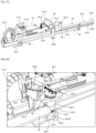
- a frame 10 is shown, attached to the ground by any means of anchoring, depending on the nature of the ground.
- This frame 10 supports a blocking module 12, operating means 14 of said blocking module 12.
- the blocking module 12 comprises a blocking head 16 and a positioning head 18.
- the frame 10 comprises a metal beam 10-1 of the IPN type, plates 10-2 secured to said metal beam 10-1, these plates being anchored to the ground, at least at both ends.
- the beam is positioned, in a known manner, parallel to the access road to a loading dock, not shown, that is to say perpendicular to the dock in front of which the vehicle must back up and be immobilized.
- the metal beam 10-1 comprises an I-section with an upper flange 10-3, a central web 10-4 and a lower flange 10-5.
- the blocking module 12 comprises a chassis 12-0 capable of moving in translation on the frame 10 and more particularly on the metal beam 10-1, rollers, not detailed, positioned under the wings make it possible to maintain guidance.
- the blocking module 12 comprises an electrical power supply 12-1, in an articulated cable tray, a hydraulic pump 12-2 with an integrated hydraulic oil tank and a distributor 12-3 so as to supply the operating means in a controlled manner 14.
- These operating means 14 comprise, in known manner, two hydraulic cylinders 14-1 and 14-2, one of a length double the other, powered by the hydraulic pump 12-2, mounted in tandem of so as to have a long stroke less than that of the 10-1 metal beam.
- Each cylinder 14-1 and 14-2 comprises a body and a rod capable of taking a maximum retracted position and a projecting position relative to said body. Tandem assembly consists of joining the two ends of the rods of the two cylinders, the body of the first cylinder on the frame 10 and the body of the second cylinder on the blocking module 12. The system is thus very compact but with a large
- the locking head 16 comprises a locking arm 16-1 of the steel bar type with circular section, in this case.
- This blocking arm 16-1 is mounted movable in translation in a sheath 16-2, a steel tube of circular section and of internal diameter equal, to the nearest clearance, to the external diameter of the blocking arm.
- the sheath 16-2 and the blocking arm 16-1 are oriented perpendicular to the metal beam 10-1 of the frame 10, therefore perpendicular to the direction of movement of the vehicles.
- the sheath 16-2 is secured to the chassis 10-2, for example by welding, so as to benefit from a connection of high mechanical resistance.
- Operating means 16-3 ensure the translational movements of the blocking arm 16-1 in said sheath 16-2.
- These operating means 16-3 advantageously consist of a hydraulic cylinder 16-4, also powered by the hydraulic pump 12-2 and its distributor.
- the end of the sleeve 16-2, on the track side, is located to the right of the edge of the track.
- the blocking arm 16-1 can take two positions, a first waiting position, retracted into the sheath 16-2, without protruding, and a second position projecting relative to the sheath 16-1, but retaining a holding part inside said sheath 16-2.
- the free end of the blocking arm 16-1 carries a crutch foot 16-4, integral with the end of the blocking arm 16-1 and oriented vertically, intended to rest on the ground of the track.
- the crutch foot 16-4 is associated with the chassis which includes compensation means 16-7.
- These compensation means include a spring 16-8 and a through rod 16-9 provided with a roller in the lower part (not shown) intended to cooperate with the underside of the upper wing.
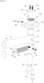
- the positioning head 18 is also mounted on the frame 12-0. This head is placed on the side of the docking path, as shown on the figures 2A , 2B And 2C .
- This positioning head comprises a central axis 20, of cylindrical section, provided with a groove 20-1 substantially in its middle part.
- a diametrical drilling 20-2 is provided in the bottom of the groove 20-1.
- This central axis 20 also includes on the upper face two threaded holes 20-3 and 20-4, the line passing through these two threaded holes being parallel to the axis of the hole 20-2.
- a positioning arm 22 is rotatably mounted.
- This positioning arm 22 comprises a hollow tube 22-1, in this case a tube of cylindrical section, one end of which is free and the other is secured to two rings 22-2 and 22-3, arranged coaxially on the central axis 20, on either side of the groove 20-1.
- the positioning arm can thus rotate freely around the central axis 20.
- Angular return means 22-4 are associated with the positioning arm and integrated into said positioning arm.
- these angular return means comprise a coil spring 22-5 taken between a stop 22-6 itself crossed by a through rod 22-7, provided with an adjustment nut 22-8 at one end beyond the stop 22-6, and the rings 22-2 and 22-3, the other end of the rod being retained by a bolt 22-9 passing through the hole 20-2 made in the groove 20-1 of the central axis 20.
- the coil spring 22-5 is tensioned by the through rod 22-7 and has a tendency to be returned to come perpendicular to the axis of the hole 20-2.
- the exploded view of the Figure 2C shows the layout in detail. The arrangement is completed by a base ring 24-1 secured to the central axis 20, by example by welding, and carrying a peripheral stop 24-10 designed to abut against the frame 12-0.
- An upper ring 24-2 ensures the guidance of the central axis 20 in the upper part, this upper ring being secured to a plate 24-3, itself secured to the chassis 12-0.
- the central axis 20 passes through the upper ring 24-2 and through a hole 24-4, provided in the plate 24-3.
- the central axis 20 emerges above the plate 24-3 and receives an anti-friction washer 24-5.
- the upper section of the central axis 20 receives a cam 26, attached to said upper section of the central axis by means of two screws 26-1 and 26-2, capable of screwing into the tapped holes 20-3 and 20- 4 located in the central axis.
- the cam 26 is a disk with an angular sector 26-3, projecting peripherally, beyond the periphery of said disk. This cam 26 carries a pin 26-5, on the outer periphery.
- This pin 26-5 is linked in an articulated manner to return means 26-6 comprising a rod 26-7 and a spring 26-8 mounted at its periphery and coming onto a stop 26-8 secured to the chassis 12-0 of one side and on a stop secured to the rod 26-7 by means of a nut for adjusting the tension of said spring.
- return means 26-6 comprising a rod 26-7 and a spring 26-8 mounted at its periphery and coming onto a stop 26-8 secured to the chassis 12-0 of one side and on a stop secured to the rod 26-7 by means of a nut for adjusting the tension of said spring.
- the rod 26-7 is substantially parallel to the line joining the two screws 26-1 and 26-2.
- a detector 26-9 completes the arrangement and detects the passage of the angular sector 26-3 in front of it.
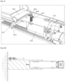
- play compensation means have been shown. Indeed, when the blocking arm 16-1 projects relative to the sheath 16-2, the blocking module 12 tilts towards the docking path.
- the crutch foot 16-4 may come into contact with the surface of the docking path and damage the surface.
- a support roller is mounted under the wing 10-1 of the metal beam at one end of a rod 28-1 while the other end passes through a support spring 28-2 with a stop 28 -3 which exerts a force on the chassis 12-0.
- the 12-0 chassis is therefore maintained, to the extent of the clearance, inclined to the side opposite the docking path.
- the locking arm 16-1 can be translated, without hooking the crutch foot 16-4.
- the operation of the vehicle blocking device according to the present invention is now described when a truck is to be positioned in the docking lane and abutting against a loading dock, this in a known manner.
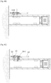
- the device according to the present invention is completed by control means, not shown, in order to carry out the different maneuvers which are now described in the context of operation, illustrated by the figures 4 .
- the device according to the present invention is in the waiting position, that is to say that the module 12 is moved back as close as possible to the loading dock in front of which a vehicle must dock, see Figure 4A .
- the vehicle having been docked the driver waits for the blocking maneuver.
- the module 12 moves along the vehicle using the movement means 14 and detects the presence of wheels in a known manner.
- the locking arm 16-1 is retracted into the sheath 16-2.
- the positioning arm 22 is perpendicular because the spring 26-8 has returned the rod 26-7 backwards and the central axis is oriented with the hole 20-2 oriented parallel to the docking path.
- the angular sector 26-3 of the cam 26 has pivoted and is opposite the sensor 26-9 which detects the appropriate orientation of the positioning arm.
- the peripheral stop 24-10 rests on the frame 12-0.
- the positioning arm 22 comes into contact with the rear wheel of the vehicle, see figure 4B .
- the arm moves back and pivots relative to the central axis 20, the spring 22-5 is compressed and the cam in the upper part sees its angular sector 26-3 leave the zone of action of the detector 26-9.
- Module 12 is immobilized.
- the blocking arm 16 is then operated because the positioning arm and the blocking arm are spaced apart by a value equal to the maximum diameter of a tire of the vehicles likely to dock at the quay. Once the blocking arm 16-1 is projected by operating the cylinder 16-3, the foot rests on the ground or is very slightly above the ground, see figure 4C .
- Module 12 is then moved back and the blocking arm comes against the vehicle tire while the angular sector 26-3 of cam 26 returns to the field of detector 26-3. Module 12 is then immobilized and the vehicle is blocked figure 4D . The red signal lights during all maneuvers remain red indicating that the vehicle is blocked. Generally, a connection is ensured with the platform door mechanism with light and sound reminders on the platform, in a known manner. When the vehicle is loaded/unloaded, the reverse maneuver is carried out and the light only turns green when module 12 is back in the initial position and the dock operator has validated the operation. For this purpose, a translational position sensor of module 12 can advantageously be provided.
- the advantages of this device are numerous.
- the first is to make the locking arm even more mechanically resistant because the stand prevents the arm from bending under the vertical component of a force exerted by the wheel in the event of an accidental start, for example.
- the vehicle moving backwards will come into abutment against the positioning arm, the latter can then come to the rear, against the force of the spring but will retract, without damage when the vehicle moves backwards.
- the positioning arm returns perpendicular under the return force of the spring 22-5 placed in the tube 22-1 of the arm. Therefore, once one or more wheels have passed, the driver of the vehicle can understand that there is a problem and then move his vehicle forward.
- the arm is then pushed in the opposite direction by the wheel and again, the positioning arm pivots and escapes any mechanical damage by retracting. Note that this is independent of the control orders which could be exercised, manually or automatically. In all cases, the vehicle cannot damage the positioning arm.
- the reliability of the device lies in the assembly which does not use any motorized element but simple return springs.
- the locking arm is compact thanks to the sheath mounting and the cylinder arranged along the length of the sheath as shown in the different figures.
Landscapes
- Engineering & Computer Science (AREA)
- Mechanical Engineering (AREA)
- Transportation (AREA)
- Body Structure For Vehicles (AREA)
- Forklifts And Lifting Vehicles (AREA)
- Vehicle Body Suspensions (AREA)
- Superstructure Of Vehicle (AREA)
Applications Claiming Priority (2)
| Application Number | Priority Date | Filing Date | Title |
|---|---|---|---|
| FR1904589A FR3095644B1 (fr) | 2019-04-30 | 2019-04-30 | Dispositif de blocage d'un vehicule devant un quai de chargement |
| PCT/EP2020/062096 WO2020221887A1 (fr) | 2019-04-30 | 2020-04-30 | Dispositif de blocage d'un vehicule devant un quai de chargement |
Publications (3)
| Publication Number | Publication Date |
|---|---|
| EP3962844A1 EP3962844A1 (fr) | 2022-03-09 |
| EP3962844B1 true EP3962844B1 (fr) | 2024-07-17 |
| EP3962844C0 EP3962844C0 (fr) | 2024-07-17 |
Family
ID=69172825
Family Applications (1)
| Application Number | Title | Priority Date | Filing Date |
|---|---|---|---|
| EP20726304.7A Active EP3962844B1 (fr) | 2019-04-30 | 2020-04-30 | Dispositif de blocage d'un vehicule devant un quai de chargement |
Country Status (6)
| Country | Link |
|---|---|
| EP (1) | EP3962844B1 (pl) |
| CA (1) | CA3136866A1 (pl) |
| ES (1) | ES2988364T3 (pl) |
| FR (1) | FR3095644B1 (pl) |
| PL (1) | PL3962844T3 (pl) |
| WO (1) | WO2020221887A1 (pl) |
Families Citing this family (5)
| Publication number | Priority date | Publication date | Assignee | Title |
|---|---|---|---|---|
| WO2015077893A1 (en) | 2013-11-29 | 2015-06-04 | 9172-9863 Québec Inc. | Wheel chock and method |
| CA3075768A1 (en) | 2017-09-14 | 2019-03-21 | 9172-9863 Quebec Inc. | Wheel chock with locking mechanism |
| WO2020093178A1 (en) | 2018-11-09 | 2020-05-14 | 9172-9863 Québec Inc. | Wheel chock handling unit and method |
| USD987542S1 (en) | 2021-03-22 | 2023-05-30 | 9172-9863 Québec Inc. | Wheel chock |
| USD995394S1 (en) | 2021-03-22 | 2023-08-15 | 9172-9863 Québec Inc. | Wheel chock |
Family Cites Families (4)
| Publication number | Priority date | Publication date | Assignee | Title |
|---|---|---|---|---|
| ES2132736T3 (es) * | 1994-10-21 | 1999-08-16 | Rite Hite Holding Corp | Inmovilizador de vehiculos accionado por las ruedas. |
| FR2957068B1 (fr) | 2010-03-06 | 2012-03-30 | A Fermetures As | Dispositif de calage a quai d'un vehicule de transport de marchandises et installation le comportant |
| FR3039528B1 (fr) | 2015-07-31 | 2017-09-01 | A S A Fermetures | Dispositif pour l'immobilisation d'un vehicule tel qu'une remorque devant un quai de chargement |
| FR3066187B1 (fr) * | 2017-05-12 | 2024-11-01 | Expresso France | Poutre ou rail de guidage, installation de transbordement et procede de mise en oeuvre |
-
2019
- 2019-04-30 FR FR1904589A patent/FR3095644B1/fr active Active
-
2020
- 2020-04-30 CA CA3136866A patent/CA3136866A1/fr active Pending
- 2020-04-30 ES ES20726304T patent/ES2988364T3/es active Active
- 2020-04-30 EP EP20726304.7A patent/EP3962844B1/fr active Active
- 2020-04-30 WO PCT/EP2020/062096 patent/WO2020221887A1/fr not_active Ceased
- 2020-04-30 PL PL20726304.7T patent/PL3962844T3/pl unknown
Also Published As
| Publication number | Publication date |
|---|---|
| EP3962844A1 (fr) | 2022-03-09 |
| ES2988364T3 (es) | 2024-11-20 |
| CA3136866A1 (fr) | 2020-11-05 |
| EP3962844C0 (fr) | 2024-07-17 |
| FR3095644B1 (fr) | 2021-07-30 |
| PL3962844T3 (pl) | 2024-10-14 |
| FR3095644A1 (fr) | 2020-11-06 |
| WO2020221887A1 (fr) | 2020-11-05 |
Similar Documents
| Publication | Publication Date | Title |
|---|---|---|
| EP3962844B1 (fr) | Dispositif de blocage d'un vehicule devant un quai de chargement | |
| EP2825428B1 (fr) | Dispositif de calage a quai de vehicule de transport de marchandises et installation le comportant | |
| EP2544979B1 (fr) | Dispositif de calage a quai d'un vehicule de transport de marchandises, installation et procédé | |
| FR2652340A1 (fr) | Dispositif de mise en place d'une cale pliante notamment devant au moins une roue d'un camion. | |
| EP0960844A1 (fr) | Cale autonome et automatique d'immobilisation de véhicules et dispositif modulaire d'immobilisation utilisant ces cales | |
| EP2089302B1 (fr) | Sabot de calage d'une roue et installation de calage motorisee | |
| FR2643623A1 (fr) | Dispositif automatique d'immobilisation d'un vehicule sur une aire notamment d'un camion devant un quai de chargement | |
| WO2017021640A1 (fr) | Dispositif pour l'immobilisation d'un vehicule tel qu'une remorque devant un quai de chargement, procede de pilotage dudit dispositif | |
| EP3307608B1 (fr) | Remorque comportant un moyen d'immobilisation, véhicule commandant l'immobilisation et l'attelage réversibles de la remorque, ensemble formé par l'attelage d'une telle remorque et d'un tel véhicule | |
| EP4255779B1 (fr) | Procédé de chargement d'un véhicule à quatre roues et convoyeur de transport associé | |
| FR3019808A1 (fr) | Dispositif de cale d'immobilisation de vehicule | |
| WO2023052435A1 (fr) | Systeme de blocage d'un vehicule devant un quai de chargement | |
| FR3107893A1 (fr) | Dispositif de blocage d'un véhicule routier devant un emplacement de chargement-déchargement | |
| EP4558430A1 (fr) | Système d'immobilisation manuel d'un véhicule devant un quai de transbordement | |
| WO2021053280A1 (fr) | Nacelle, notamment nacelle élévatrice | |
| EP0565468B1 (fr) | Rampe de chargement adossée à actionnement manuel, compensée par ressorts | |
| EP0765779A1 (fr) | Dispositif de manutention pour charger ou décharger un dévidoir porté par un véhicule | |
| EP4448426A1 (fr) | Système de butée d'un quai de chargement | |
| EP1992320B1 (fr) | Meuble déplaçable à roue motrice et directrice | |
| FR3126118A1 (fr) | Véhicule à auto-équilibrage avec dispositif anti-bascule | |
| FR2765844A1 (fr) | Dispositif de calage d'un vehicule automobile sur un plan de chargement | |
| FR2891267A1 (fr) | Prehenseur a aimant(s) permanent(s) perfectionne | |
| CA2930721A1 (fr) | Dispositif d'abaissement de la caisse d'un vehicule comportant un moyen de detection de la position haute | |
| FR3007012A1 (fr) | Plateforme elevatrice de personnel integrant un reposoir pour immobiliser le panier de la plateforme |
Legal Events
| Date | Code | Title | Description |
|---|---|---|---|
| STAA | Information on the status of an ep patent application or granted ep patent |
Free format text: STATUS: UNKNOWN |
|
| STAA | Information on the status of an ep patent application or granted ep patent |
Free format text: STATUS: THE INTERNATIONAL PUBLICATION HAS BEEN MADE |
|
| PUAI | Public reference made under article 153(3) epc to a published international application that has entered the european phase |
Free format text: ORIGINAL CODE: 0009012 |
|
| STAA | Information on the status of an ep patent application or granted ep patent |
Free format text: STATUS: REQUEST FOR EXAMINATION WAS MADE |
|
| 17P | Request for examination filed |
Effective date: 20211025 |
|
| AK | Designated contracting states |
Kind code of ref document: A1 Designated state(s): AL AT BE BG CH CY CZ DE DK EE ES FI FR GB GR HR HU IE IS IT LI LT LU LV MC MK MT NL NO PL PT RO RS SE SI SK SM TR |
|
| DAV | Request for validation of the european patent (deleted) | ||
| DAX | Request for extension of the european patent (deleted) | ||
| GRAP | Despatch of communication of intention to grant a patent |
Free format text: ORIGINAL CODE: EPIDOSNIGR1 |
|
| STAA | Information on the status of an ep patent application or granted ep patent |
Free format text: STATUS: GRANT OF PATENT IS INTENDED |
|
| RIC1 | Information provided on ipc code assigned before grant |
Ipc: B60T 3/00 20060101ALI20240304BHEP Ipc: B65G 69/00 20060101ALI20240304BHEP Ipc: B65G 69/34 20060101AFI20240304BHEP |
|
| INTG | Intention to grant announced |
Effective date: 20240404 |
|
| GRAS | Grant fee paid |
Free format text: ORIGINAL CODE: EPIDOSNIGR3 |
|
| GRAA | (expected) grant |
Free format text: ORIGINAL CODE: 0009210 |
|
| STAA | Information on the status of an ep patent application or granted ep patent |
Free format text: STATUS: THE PATENT HAS BEEN GRANTED |
|
| AK | Designated contracting states |
Kind code of ref document: B1 Designated state(s): AL AT BE BG CH CY CZ DE DK EE ES FI FR GB GR HR HU IE IS IT LI LT LU LV MC MK MT NL NO PL PT RO RS SE SI SK SM TR |
|
| REG | Reference to a national code |
Ref country code: CH Ref legal event code: EP |
|
| REG | Reference to a national code |
Ref country code: DE Ref legal event code: R096 Ref document number: 602020034107 Country of ref document: DE |
|
| REG | Reference to a national code |
Ref country code: IE Ref legal event code: FG4D Free format text: LANGUAGE OF EP DOCUMENT: FRENCH |
|
| U01 | Request for unitary effect filed |
Effective date: 20240813 |
|
| U07 | Unitary effect registered |
Designated state(s): AT BE BG DE DK EE FI FR IT LT LU LV MT NL PT SE SI Effective date: 20240826 |
|
| REG | Reference to a national code |
Ref country code: ES Ref legal event code: FG2A Ref document number: 2988364 Country of ref document: ES Kind code of ref document: T3 Effective date: 20241120 |
|
| PG25 | Lapsed in a contracting state [announced via postgrant information from national office to epo] |
Ref country code: NO Free format text: LAPSE BECAUSE OF FAILURE TO SUBMIT A TRANSLATION OF THE DESCRIPTION OR TO PAY THE FEE WITHIN THE PRESCRIBED TIME-LIMIT Effective date: 20241017 |
|
| PG25 | Lapsed in a contracting state [announced via postgrant information from national office to epo] |
Ref country code: GR Free format text: LAPSE BECAUSE OF FAILURE TO SUBMIT A TRANSLATION OF THE DESCRIPTION OR TO PAY THE FEE WITHIN THE PRESCRIBED TIME-LIMIT Effective date: 20241018 |
|
| PG25 | Lapsed in a contracting state [announced via postgrant information from national office to epo] |
Ref country code: IS Free format text: LAPSE BECAUSE OF FAILURE TO SUBMIT A TRANSLATION OF THE DESCRIPTION OR TO PAY THE FEE WITHIN THE PRESCRIBED TIME-LIMIT Effective date: 20241117 |
|
| PG25 | Lapsed in a contracting state [announced via postgrant information from national office to epo] |
Ref country code: HR Free format text: LAPSE BECAUSE OF FAILURE TO SUBMIT A TRANSLATION OF THE DESCRIPTION OR TO PAY THE FEE WITHIN THE PRESCRIBED TIME-LIMIT Effective date: 20240717 |
|
| PG25 | Lapsed in a contracting state [announced via postgrant information from national office to epo] |
Ref country code: RS Free format text: LAPSE BECAUSE OF FAILURE TO SUBMIT A TRANSLATION OF THE DESCRIPTION OR TO PAY THE FEE WITHIN THE PRESCRIBED TIME-LIMIT Effective date: 20241017 |
|
| PG25 | Lapsed in a contracting state [announced via postgrant information from national office to epo] |
Ref country code: RS Free format text: LAPSE BECAUSE OF FAILURE TO SUBMIT A TRANSLATION OF THE DESCRIPTION OR TO PAY THE FEE WITHIN THE PRESCRIBED TIME-LIMIT Effective date: 20241017 Ref country code: NO Free format text: LAPSE BECAUSE OF FAILURE TO SUBMIT A TRANSLATION OF THE DESCRIPTION OR TO PAY THE FEE WITHIN THE PRESCRIBED TIME-LIMIT Effective date: 20241017 Ref country code: IS Free format text: LAPSE BECAUSE OF FAILURE TO SUBMIT A TRANSLATION OF THE DESCRIPTION OR TO PAY THE FEE WITHIN THE PRESCRIBED TIME-LIMIT Effective date: 20241117 Ref country code: HR Free format text: LAPSE BECAUSE OF FAILURE TO SUBMIT A TRANSLATION OF THE DESCRIPTION OR TO PAY THE FEE WITHIN THE PRESCRIBED TIME-LIMIT Effective date: 20240717 Ref country code: GR Free format text: LAPSE BECAUSE OF FAILURE TO SUBMIT A TRANSLATION OF THE DESCRIPTION OR TO PAY THE FEE WITHIN THE PRESCRIBED TIME-LIMIT Effective date: 20241018 |
|
| PG25 | Lapsed in a contracting state [announced via postgrant information from national office to epo] |
Ref country code: SM Free format text: LAPSE BECAUSE OF FAILURE TO SUBMIT A TRANSLATION OF THE DESCRIPTION OR TO PAY THE FEE WITHIN THE PRESCRIBED TIME-LIMIT Effective date: 20240717 |
|
| U20 | Renewal fee for the european patent with unitary effect paid |
Year of fee payment: 6 Effective date: 20250320 |
|
| PG25 | Lapsed in a contracting state [announced via postgrant information from national office to epo] |
Ref country code: CZ Free format text: LAPSE BECAUSE OF FAILURE TO SUBMIT A TRANSLATION OF THE DESCRIPTION OR TO PAY THE FEE WITHIN THE PRESCRIBED TIME-LIMIT Effective date: 20240717 |
|
| PGFP | Annual fee paid to national office [announced via postgrant information from national office to epo] |
Ref country code: PL Payment date: 20250319 Year of fee payment: 6 |
|
| PG25 | Lapsed in a contracting state [announced via postgrant information from national office to epo] |
Ref country code: SK Free format text: LAPSE BECAUSE OF FAILURE TO SUBMIT A TRANSLATION OF THE DESCRIPTION OR TO PAY THE FEE WITHIN THE PRESCRIBED TIME-LIMIT Effective date: 20240717 |
|
| PGFP | Annual fee paid to national office [announced via postgrant information from national office to epo] |
Ref country code: GB Payment date: 20250313 Year of fee payment: 6 |
|
| PLBE | No opposition filed within time limit |
Free format text: ORIGINAL CODE: 0009261 |
|
| STAA | Information on the status of an ep patent application or granted ep patent |
Free format text: STATUS: NO OPPOSITION FILED WITHIN TIME LIMIT |
|
| 26N | No opposition filed |
Effective date: 20250422 |
|
| PGFP | Annual fee paid to national office [announced via postgrant information from national office to epo] |
Ref country code: ES Payment date: 20250506 Year of fee payment: 6 |
|
| REG | Reference to a national code |
Ref country code: CH Ref legal event code: H13 Free format text: ST27 STATUS EVENT CODE: U-0-0-H10-H13 (AS PROVIDED BY THE NATIONAL OFFICE) Effective date: 20251125 |