EP3962836B1 - Überwachung des vollen zustandes von behältern - Google Patents
Überwachung des vollen zustandes von behältern Download PDFInfo
- Publication number
- EP3962836B1 EP3962836B1 EP20798117.6A EP20798117A EP3962836B1 EP 3962836 B1 EP3962836 B1 EP 3962836B1 EP 20798117 A EP20798117 A EP 20798117A EP 3962836 B1 EP3962836 B1 EP 3962836B1
- Authority
- EP
- European Patent Office
- Prior art keywords
- container
- monitoring
- waste
- sensors
- compactor
- Prior art date
- Legal status (The legal status is an assumption and is not a legal conclusion. Google has not performed a legal analysis and makes no representation as to the accuracy of the status listed.)
- Active
Links
Images




Classifications
-
- B—PERFORMING OPERATIONS; TRANSPORTING
- B65—CONVEYING; PACKING; STORING; HANDLING THIN OR FILAMENTARY MATERIAL
- B65F—GATHERING OR REMOVAL OF DOMESTIC OR LIKE REFUSE
- B65F1/00—Refuse receptacles; Accessories therefor
- B65F1/14—Other constructional features; Accessories
- B65F1/1405—Compressing means incorporated in, or specially adapted for, refuse receptacles
-
- B—PERFORMING OPERATIONS; TRANSPORTING
- B65—CONVEYING; PACKING; STORING; HANDLING THIN OR FILAMENTARY MATERIAL
- B65F—GATHERING OR REMOVAL OF DOMESTIC OR LIKE REFUSE
- B65F1/00—Refuse receptacles; Accessories therefor
- B65F1/14—Other constructional features; Accessories
- B65F1/1484—Other constructional features; Accessories relating to the adaptation of receptacles to carry identification means
-
- G—PHYSICS
- G01—MEASURING; TESTING
- G01F—MEASURING VOLUME, VOLUME FLOW, MASS FLOW OR LIQUID LEVEL; METERING BY VOLUME
- G01F17/00—Methods or apparatus for determining the capacity of containers or cavities, or the volume of solid bodies
-
- G—PHYSICS
- G01—MEASURING; TESTING
- G01F—MEASURING VOLUME, VOLUME FLOW, MASS FLOW OR LIQUID LEVEL; METERING BY VOLUME
- G01F23/00—Indicating or measuring liquid level or level of fluent solid material, e.g. indicating in terms of volume or indicating by means of an alarm
- G01F23/0007—Indicating or measuring liquid level or level of fluent solid material, e.g. indicating in terms of volume or indicating by means of an alarm for discrete indicating and measuring
-
- G—PHYSICS
- G01—MEASURING; TESTING
- G01F—MEASURING VOLUME, VOLUME FLOW, MASS FLOW OR LIQUID LEVEL; METERING BY VOLUME
- G01F23/00—Indicating or measuring liquid level or level of fluent solid material, e.g. indicating in terms of volume or indicating by means of an alarm
- G01F23/04—Indicating or measuring liquid level or level of fluent solid material, e.g. indicating in terms of volume or indicating by means of an alarm by dip members, e.g. dip-sticks
-
- G—PHYSICS
- G01—MEASURING; TESTING
- G01F—MEASURING VOLUME, VOLUME FLOW, MASS FLOW OR LIQUID LEVEL; METERING BY VOLUME
- G01F23/00—Indicating or measuring liquid level or level of fluent solid material, e.g. indicating in terms of volume or indicating by means of an alarm
- G01F23/30—Indicating or measuring liquid level or level of fluent solid material, e.g. indicating in terms of volume or indicating by means of an alarm by floats
- G01F23/64—Indicating or measuring liquid level or level of fluent solid material, e.g. indicating in terms of volume or indicating by means of an alarm by floats of the free float type without mechanical transmission elements
- G01F23/72—Indicating or measuring liquid level or level of fluent solid material, e.g. indicating in terms of volume or indicating by means of an alarm by floats of the free float type without mechanical transmission elements using magnetically actuated indicating means
- G01F23/74—Indicating or measuring liquid level or level of fluent solid material, e.g. indicating in terms of volume or indicating by means of an alarm by floats of the free float type without mechanical transmission elements using magnetically actuated indicating means for sensing changes in level only at discrete points
-
- G—PHYSICS
- G01—MEASURING; TESTING
- G01F—MEASURING VOLUME, VOLUME FLOW, MASS FLOW OR LIQUID LEVEL; METERING BY VOLUME
- G01F23/00—Indicating or measuring liquid level or level of fluent solid material, e.g. indicating in terms of volume or indicating by means of an alarm
- G01F23/80—Arrangements for signal processing
- G01F23/802—Particular electronic circuits for digital processing equipment
- G01F23/804—Particular electronic circuits for digital processing equipment containing circuits handling parameters other than liquid level
-
- G—PHYSICS
- G06—COMPUTING OR CALCULATING; COUNTING
- G06Q—INFORMATION AND COMMUNICATION TECHNOLOGY [ICT] SPECIALLY ADAPTED FOR ADMINISTRATIVE, COMMERCIAL, FINANCIAL, MANAGERIAL OR SUPERVISORY PURPOSES; SYSTEMS OR METHODS SPECIALLY ADAPTED FOR ADMINISTRATIVE, COMMERCIAL, FINANCIAL, MANAGERIAL OR SUPERVISORY PURPOSES, NOT OTHERWISE PROVIDED FOR
- G06Q10/00—Administration; Management
- G06Q10/08—Logistics, e.g. warehousing, loading or distribution; Inventory or stock management
-
- B—PERFORMING OPERATIONS; TRANSPORTING
- B65—CONVEYING; PACKING; STORING; HANDLING THIN OR FILAMENTARY MATERIAL
- B65F—GATHERING OR REMOVAL OF DOMESTIC OR LIKE REFUSE
- B65F2210/00—Equipment of refuse receptacles
- B65F2210/12—Crushing means
-
- B—PERFORMING OPERATIONS; TRANSPORTING
- B65—CONVEYING; PACKING; STORING; HANDLING THIN OR FILAMENTARY MATERIAL
- B65F—GATHERING OR REMOVAL OF DOMESTIC OR LIKE REFUSE
- B65F2210/00—Equipment of refuse receptacles
- B65F2210/128—Data transmitting means
-
- B—PERFORMING OPERATIONS; TRANSPORTING
- B65—CONVEYING; PACKING; STORING; HANDLING THIN OR FILAMENTARY MATERIAL
- B65F—GATHERING OR REMOVAL OF DOMESTIC OR LIKE REFUSE
- B65F2210/00—Equipment of refuse receptacles
- B65F2210/144—Level detecting means
- B65F2210/1443—Electrical
-
- B—PERFORMING OPERATIONS; TRANSPORTING
- B65—CONVEYING; PACKING; STORING; HANDLING THIN OR FILAMENTARY MATERIAL
- B65F—GATHERING OR REMOVAL OF DOMESTIC OR LIKE REFUSE
- B65F2210/00—Equipment of refuse receptacles
- B65F2210/168—Sensing means
-
- B—PERFORMING OPERATIONS; TRANSPORTING
- B65—CONVEYING; PACKING; STORING; HANDLING THIN OR FILAMENTARY MATERIAL
- B65F—GATHERING OR REMOVAL OF DOMESTIC OR LIKE REFUSE
- B65F2210/00—Equipment of refuse receptacles
- B65F2210/20—Temperature sensing means
-
- H—ELECTRICITY
- H04—ELECTRIC COMMUNICATION TECHNIQUE
- H04W—WIRELESS COMMUNICATION NETWORKS
- H04W4/00—Services specially adapted for wireless communication networks; Facilities therefor
- H04W4/02—Services making use of location information
- H04W4/025—Services making use of location information using location based information parameters
- H04W4/027—Services making use of location information using location based information parameters using movement velocity, acceleration information
Definitions
- the present disclosure is directed generally to systems and methods for monitoring containers, such as fullness of containers, including containers for waste and recycling services.
- Waste management involves receipt, collection, storage, and transportation of garbage and/or recyclables, such as household trash, cans, cardboard, paper, food waste, and/or other refuse.
- garbage or recycling trucks may travel to a dumpster, curbside container, alley container, recycling bin, or another waste container to empty the container into the truck on a periodic basis, such as a weekly basis, and to transport the waste to a processing facility. While on the truck, a compactor may compress the waste into a smaller volume for more efficient use of the truck's capacity.
- Another type of container is a large container that is temporarily positioned at a waste collection site and retrieved when it is full and/or when the waste collection is complete.
- construction demolition sites may use a roll-off to gather demolition debris until the roll-off is taken away from the site by a truck or other vehicle.
- Other types of containers include self-contained compactors and stationary compactors, which may include fixed or mobile compactor systems connected to containers.
- waste management involves collecting waste in several types of containers, including compactor devices, front-load containers, rear-load containers, top-load containers, and other types of containers, and eventually transporting the waste for disposal in a remote location.
- Waste management involves several challenges. For example, containers, such as compactors, may be overloaded by users between periodic pickup times, or they may be underutilized and picked up too often. Sometimes, servicing containers or collecting from containers can be missed, which results in waste overflow. Aspects of the present technology are generally directed to addressing these inefficiencies and other challenges in the waste management industry.
- US 2019/0019167 A1 discloses a system for garbage trucks including a device configured to measure the waste volume using volume sensors.
- US 2014/0172174 A1 discloses a control system for trash compactors, where the control system includes a fullness sensor.
- WO 2019/040946 discloses a time of flight sensor for determining fullness of a waste container.
- Some existing systems may monitor fullness by sensing pressure in a hydraulic cylinder of a compactor system, such as by tapping into or piggybacking on the control system of the compactor system. Such existing systems may require cumbersome integration with proprietary or otherwise specific or unique systems, making some specific systems incompatible with broad ranges of systems in the waste management industry. Embodiments of the present technology provide universal monitoring systems that can be retrofit to a variety of containers.
- Representative embodiments of the present technology include a waste container monitoring system comprising a waste compactor system, which comprises a waste container and a hydraulic line. It comprises further a monitoring assembly configured to be connected to the waste compactor system or the waste container, wherein the monitoring assembly comprises a hub device and one or more sensors connected to the hub device via one or more wired and/or wireless connections, wherein the one or more sensors are positioned on or in the waste container or the waste compactor system. It comprises further a remote processing system and a communication connection connecting the monitoring assembly to the remote processing system.
- the one or more sensors are configured to monitor one or more conditions of the container, wherein the one or more sensors comprise a pressure sensor connected to the hydraulic line and a connection sensor configured to detect the presence or absence of a connection of the waste compactor system to power or to a fixed connection.
- the hub device comprises a controller configured to determine fullness of the waste container based on pressure data from the pressure sensor.
- the communication connection is configured to communicate the one or more conditions to the remote processing system.
- Embodiments of the present technology provide monitoring capabilities for waste containers and improved efficiency in waste management.
- the present technology is generally directed to monitoring of containers, such as monitoring the fullness of containers, including containers for waste and recycling services, and associated systems and methods.
- Various embodiments of the technology will now be described. The following description provides specific details for a thorough understanding and enabling description of these embodiments. One skilled in the art will understand, however, that the invention may be practiced without many of these details. Additionally, conventional or well-known aspects of sensors, communication devices, microcontrollers, and compactors may not be shown or described in detail so as to avoid unnecessarily obscuring the relevant description of the various embodiments. Any of the features described herein may be combined in suitable manners with any of the other features described herein without deviating from the scope of the present technology. Accordingly, embodiments of the present technology may include additional elements, or may exclude some of the elements described below with reference to Figures 1-6 , which illustrate examples of the technology.
- Some embodiments of the technology described below may take the form of computer- or controller-executable instructions, including routines executed by a programmable computer or controller.
- the technology can be practiced on computer/controller systems other than those shown and described below.
- the technology can be embodied in a special-purpose computer, controller or data processor that is specifically programmed, configured or constructed to perform one or more of the computer-executable instructions described below.
- the terms "computer” and “controller” as generally used herein refer to any data processor and can include Internet appliances and hand-held devices (including palm-top computers, wearable computers, cellular or mobile phones, multiprocessor systems, processor-based or programmable consumer electronics, network computers, mini computers and the like). Information handled by these computers can be presented at any suitable display medium, including an LCD.
- the technology can also be practiced in distributed environments, where tasks or modules are performed by remote processing devices that are linked through a communications network.
- program modules or subroutines may be located in local and remote memory storage devices.
- aspects of the technology described below may be stored or distributed on computer-readable media, including magnetic or optically readable or removable computer disks, as well as distributed electronically over networks. Data structures and transmissions of data particular to aspects of the technology are also encompassed within the scope of the embodiments of the technology.
- Communication connections between components may include a direct, wired coupling or a wireless protocol such as, Bluetooth ® , Wi-Fi TM , a LAN, a WAN, a cellular network, a WLAN, other IEEE 802.xx networks, the Internet, or other connections suitable for communicating data.
- a wireless protocol such as, Bluetooth ® , Wi-Fi TM , a LAN, a WAN, a cellular network, a WLAN, other IEEE 802.xx networks, the Internet, or other connections suitable for communicating data.
- the present technology provides devices or systems that may be configured with one or more digital or analog sensors to analyze or detect fullness of containers, such as waste containers, to monitor the presence or absence of containers, and/or to monitor other conditions of containers.
- the devices or systems may be connected to a cloud-based monitoring, alerting, and reporting system to monitor any type of waste container.
- the present technology improves efficiency of waste management systems and processes, and may be retrofitted into existing systems and processes. Specific details of several embodiments of the present technology are described herein with reference to waste management, which may involve garbage and/or recyclables, and/or other refuse.
- the present technology may be used for other processes or in other industries that involve containing materials.
- FIG. 1 illustrates a container 100 and a monitoring system 110 in accordance with embodiments of the present technology.
- the monitoring system 110 may include a monitoring device 120 connected to (such as positioned or mounted in) the container 100.
- the monitoring system 110 may further include a remote processing system 130, which may communicate with the monitoring device 120 via one or more communication connections 140.
- the monitoring device 120 monitors conditions of the container 100.
- the monitoring device 120 may monitor fullness of the container 100 (i.e., an amount of waste 150, using an included ultrasonic sensor), and/or it may monitor an orientation of the container 100 (for example, whether it is tipped over or otherwise rotated, using an included accelerometer or other motion sensor), and/or it may monitor a location of the container 100 (for example, via included GPS systems), and/or it may monitor a temperature of the container 100.
- the monitoring device 120 may monitor fullness and/or other conditions of the container 100 in other ways described herein or ways known in the art.
- the monitoring device 120 communicates with the remote processing system 130 for remote analysis of information from the monitoring device 120.
- the remote processing system 130 may include database and/or scheduling systems such as the iWaste ® Monitoring System by Waste Harmonics of New York, USA.
- the remote processing system 130 includes a scheduling system configured to autonomously schedule servicing of the container (such as collecting or emptying).
- the monitoring device 120 includes circuitry, sensors, processing and controller components, communication components, and/or other components described herein, which may be contained within a housing 160.
- the housing 160 may include metal, plastic, resin, and/or another material suitable for providing impact resistance, water resistance, and/or resistance to other substances commonly found in waste.
- the housing 160 and the components therein may be positioned in a location of the container 100 suitable for facilitating sensing functions of the monitoring components in the device 120, such as an upper rear corner of the container 100, or another location.
- the housing 160 is triangular or wedge-shaped, or it may be other shapes suitable for positioning or mounting in the container 100.
- the monitoring device 120 may be attached to the container 100 using one or more magnets, adhesives, mechanical fasteners (such as screws or bolts), or the monitoring device 120 may be integral with the container 100 (such that the container 100 includes the housing 160, for example).
- the monitoring device 120 measures conditions of the container 100 that may be relevant to whether the container 100 has been picked up or emptied.
- an accelerometer in the device 120 may sense whether the container 100 has been rotated.
- a position sensor (such as GPS) may indicate whether the container 100 has been moved.
- An ultrasonic sensor in the monitoring device 120 may be calibrated to determine relative fullness of the container 100.
- the monitoring device 120 communicates with the remote processing system 130, which indicates to a user or an automated scheduler whether the container 100 has likely been emptied, whether it needs to be emptied, or whether it is empty, for example.
- schedulers may more efficiently collect waste from the container 100 or otherwise verify that waste has been collected.
- a system connected to the monitoring device 120 such as the remote processing system 130, may issue an alert if a pickup is missed, or determine pickup dates based on analysis of accumulation in various containers in the system.
- Figure 1 illustrates a common dumpster as the container 100.
- Embodiments of the present technology may be implemented in other containers 100, such as a curbside container, an alley container, a recycling bin, a trash can, a roll-off, a front-load container, a rear-load container, a container associated with a mechanical compactor (such as a stationary compactor or a self-contained compactor), or another container suitable for containing waste, and it may be mounted or carried on a vehicle or positioned on a surface (such as a driveway, parking lot, or other usual location for a waste container).
- the monitoring system 110 may be used in containers sized ten yards or smaller, or it may be used in larger containers.
- Figure 1A illustrates a monitoring device 120 in accordance with embodiments of the present technology.
- the monitoring device may include an ultrasonic sensor 170 and/or other sensor positioned in the housing 160 and oriented to face an interior of the container 100.
- the housing 160 may include a front portion 180 attached to a rear portion 190 using one or more fasteners 195 or another suitable attachment, such as adhesive.
- the monitoring device 120 may be approximately 5 inches wide, 6.5 inches tall, and 4.75 inches deep, although any size and shape suitable for holding sensors and electronics in the container 100 may be used in accordance with various embodiments.
- monitoring device 120 is illustrated as being contained within a housing 160, in some embodiments, one or more components of the monitoring device 120 may be external to the housing 160.
- one or more sensors or communication devices may be external to the housing 160 and connected to the remainder of the monitoring device 120.
- FIG. 2 illustrates a compactor system 200 and a monitoring system 210 for monitoring the compactor system 200 in accordance with embodiments of the present technology.
- the compactor system 200 may include a container 220 and a compactor assembly 230 for compacting waste or recyclables in the container 220.
- the compactor system 200 may be positioned on a surface or it may be movable, such as being positioned on a vehicle.
- the compactor system 200 may be similar to existing compactor systems, including self-contained compactor systems and stationary compactor systems, such that the monitoring system 210 may be retrofit to existing compactor systems.
- the monitoring system 210 may be similar to the monitoring system 110 described above and illustrated in Figure 1 , but it may include more sensors, fewer sensors, or different types of sensors and monitoring assemblies than the monitoring system 110 described above with regard to Figure 1 .
- the monitoring system 210 may communicate with the remote processing system 130 via one or more communication connections 140.
- the monitoring system 210 includes a monitoring assembly 240, which may be similar to the monitoring device 120 described above with regard to Figure 1 , but instead of including all components within one housing, the monitoring assembly 240 may include a hub device 250 connected to one or more sensors 260, 270, 280 distributed around various elements of the compactor system 200.
- the hub device 250 may be positioned on or in a control panel of the compactor system 200 or elsewhere on the compactor system 200 or on another structure or support, while the sensors 260, 270, 280 are positioned in locations suitable to performing their given function.
- the sensors 260, 270, 280 may be connected to the hub wirelessly and/or by lead wires.
- the monitoring assembly 240 may be powered by a connection to an electrical grid, a battery, a power relay of the compactor system 200, and/or another suitable power source.
- the hub device 250 may contain connectors for receiving signals from the sensors 260, 270, 280, communication devices for communicating with the remote processing system 130, processing devices or controllers described herein, and/or other equipment.
- the monitoring assembly 240 includes a pressure and/or temperature sensor 260 connected to the hub device 250, such as a pressure or temperature transducer, which may be installed in or connected to a hydraulic line of the compactor assembly 230.
- the pressure or temperature sensor 260 may be installed on an "A" port hydraulic line to measure pressure of an outward stroke of the compactor blade as it moves through the container 220, or temperature of the fluid in the hydraulic line.
- the pressure or temperature sensor 260 measures pressure or temperature to determine fullness of the container 220, for example, based on the state of the hydraulic fluid in the compactor assembly 230. For example, pressure and temperature of the hydraulic fluid may be high when the compactor assembly 230 is pushing against a full load of waste in the container 220.
- the monitoring assembly 240 may include a proximity sensor 270 positioned on or near the compactor assembly 230 and targeted at the container 220 to determine the presence or absence of the container 220.
- the proximity sensor 270 may facilitate detection of whether or when the container 220 has been removed from the compactor system 200, such as when the container 220 is removed for emptying and later replaced.
- a proximity sensor 270 may be positioned near the compactor system 200 on a wall, pole, or other support, to detect the presence or absence of the entire compactor system 200.
- the monitoring assembly 240 may include a connection sensor 280, which may be a plug or other connector that signals the presence of the compactor system 200 when it is connected to power and/or another fixed connection, and it may signal the absence of the compactor system 200 when it is disconnected.
- a connection sensor 280 may be a plug or other connector that signals the presence of the compactor system 200 when it is connected to power and/or another fixed connection, and it may signal the absence of the compactor system 200 when it is disconnected.
- other sensors may be implemented, such as ultrasonic sensors positioned in the container 220, GPS sensors, tipping sensors (such as accelerometers), Bluetooth ® beacons, and/or other sensors suitable for indicating position, presence, absence, fullness, orientation, and/or other conditions of a compactor system or the container of a compactor system (similar to the monitoring device 120 described above with regard to Figure 1 ).
- the monitoring assembly 240 may include a fluid sensor assembly positioned on a hydraulic fluid reservoir of the compactor assembly 230, according to an embodiment of the present technology described in additional detail below.
- the monitoring assembly 240 measures conditions of the container 220 and/or the compactor system 200 that may be relevant to whether the container 220 and/or the compactor system 200 has been picked up or emptied.
- the monitoring assembly 240 communicates with the remote processing system 130, which indicates to a user or an automated scheduler whether the container 220 and/or the compactor system 200 has likely been emptied, whether it needs to be emptied, or whether it is empty, for example.
- schedulers may more efficiently collect waste or otherwise verify that waste has been collected.
- a system connected to the monitoring assembly 240 may issue an alert if a pickup is missed, and/or determine pickup dates based on analysis of accumulation in various containers and/or compactors in the system.
- the monitoring assembly 240 may include lights (such as LEDs) to indicate a status of the container 220 and/or the compactor system 200, such as whether it is full, empty, or has recently been serviced or collected.
- the monitoring system 210 may be implemented in baler systems instead of compactor systems, for example, to count bales of cardboard and/or other material using suitable sensors connected to a hub device 250.
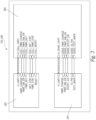
- FIG. 3 illustrates a schematic of several components of the monitoring device 120 or the monitoring assembly 240 in accordance with embodiments of the present technology.
- the present disclosure may refer to the monitoring assembly 240, although the components of the monitoring assembly 240 and the monitoring device 120 may be similar in some embodiments (for example, the monitoring device 120 may be an integrated version of the monitoring assembly 240 with all components contained in or carried by the housing 160).
- the monitoring assembly 240 includes a controller 300, such as a microcontroller.
- the monitoring assembly 240 also includes one or more sensors 310 connected to the controller 300.
- the monitoring assembly 240 also includes one or more communication devices 320, which facilitate communication connections (for example, with a remote processing system).
- the monitoring assembly 240 and its components may be powered by any suitable power source, including battery power or an alternating current or direct current power source.
- the sensors 310 may include any of the sensors described herein, such as ultrasonic sensors (for fullness), accelerometers (for tipping or motion), pressure sensors (for compactor fullness), temperature sensors, GPS sensors (position), Bluetooth ® sensors, and/or proximity sensors (to detect presence or absence of a container or compactor).
- the communication device 320 may include a cellular modem (operating on a 3G, 4G, LTE, 5G, or other suitable mobile or cellular network), a hardwired internet device, a wireless internet device, and/or another device suitable for facilitating communication connections with external devices, such as a remote processing system 130.
- any suitable number of sensors and/or communication devices may be connected to the controller 300 in various embodiments of the present technology, depending on the number of communication connections and sensors implemented in a given application for monitoring containers or compactor systems.
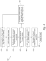
- FIG 4 illustrates a boot sequence 400 of the controller 300 ( Figure 3 ).
- the boot sequence 400 may be performed by instructions programmed in the controller 300 and executed by the controller 300.
- the controller 300 may be powered by a power supply, which may receive AC or DC power (e.g., 120VAC or 3.6VDC).
- the power supply receives power
- the controller loads bootloader instructions.
- the bootloader verifies the function of the components in the monitoring system or device, and verifies the communication device 320 (such as a cellular modem) is connected to a remote system, such as the remote processing system 130.
- the communication device 320 such as a cellular modem
- the bootloader inquires whether a firmware update is available or necessary (for example, an update to calibrate one or more of the various sensors). If a firmware update is available or necessary, in block 450, the bootloader downloads the update from the remote system or another source (such as the remote processing system 130), and the bootloader reboots the controller to begin at block 410 again. In some embodiments, the bootloader may be scheduled to reboot the controller on a periodic basis to trigger downloading of updates. Updates may include sensor configuration and/or calibration information, communication information, security updates, and/or other updates suitable for maintaining function of the monitoring assembly or the monitoring device.
- the bootloader applies configuration parameters to the controller, such as sensor settings.
- the controller 300 may receive configuration parameters from the remote processing system 130, at startup of the controller 300 or at another time during operation.
- the configuration parameters may be updated in the controller 300 by a push message (such as a short message system communication or other communication from the remote processing system 130 or another remote system), and/or by queuing the new parameters in a database connected to the controller 300 to be read at a specific time, such as after the next communication (write cycle) to the database of the remote processing system 130.
- a push message such as a short message system communication or other communication from the remote processing system 130 or another remote system
- queuing the new parameters in a database connected to the controller 300 to be read at a specific time, such as after the next communication (write cycle) to the database of the remote processing system 130.
- the bootloader sets an initial state of the connected components (for example, the sensor inputs and one or more onboard LEDs). For example, using the configuration parameters, the controller sets the state of the LEDs to indicate a status of the system.
- the controller 300 may be connected to an LED visible to a user to set the LED to indicate fullness, such as by being green (or another suitable color) to indicate empty, or red (or another suitable color) to indicate a full container.
- a user may selectively customize the colors associated with fullness or emptiness.
- the bootloader may set the initial state (color) of the LED on startup or at another time during operation.
- the bootloader initiates the operating system on the controller, and the controller is ready to receive and process data, and to operate the monitoring assembly or devices described herein.
- Figure 5 illustrates an operational sequence 500 of the controller 300.
- the controller 300 may be programmed with instructions that, when executed, carry out the operational sequence 500.
- the operational sequence instructions may be initiated by the bootloader described above and illustrated with regard to Figure 4 .
- one or more sensors receive input, such as temperature information, ultrasonic sensor information, pressure information, and/or other sensor information.
- the input may be in the form of an analog or digital signal, which, in block 520, is transmitted to the controller 300 to be processed.
- an analog ultrasonic sensor may emit ultrasonic waves and measure the waves received back from reflection in the container.
- the ultrasonic sensor may communicate an analog or digital signal to the controller 300, for example, as a one to five volt signal.
- the controller 300 may receive data from the sensors 310 as signals passed into the controller 300 by pins or as a PNP connection, or via other means.
- the controller 300 may process the signal from the sensor(s) 310 to determine a measure of fullness, a location of the container, a temperature of the container, an orientation of the container (e.g., tipping), and/or other metrics depending on the type of sensor 310.
- the controller 300 may process signals using onboard firmware or other instructions.
- the controller 300 may process the signal from the ultrasonic sensor to determine fullness as a function of the signal from the ultrasonic sensor that has been calibrated for a given container (for example, with testing and analysis).
- the controller 300 may process the signal from a pressure sensor in a compactor hydraulic system to determine fullness as a calibrated function of pressure.
- the controller 300 processes data from the sensor(s) according to standards set by the Institute of Electrical and Electronics Engineers (IEEE).
- data from the sensor(s) may be transmitted to the remote processing system 130 for analysis and/or processing, or other systems or devices may process the data.
- the controller 300 transmits the processed data-which may include pressure values, fullness metrics (such as percentage-full or percentage-empty, or absolute values such as approximate weight), GPS location, orientation (tipping), or other values- to the communication device 320 for transmission to the remote processing system 130, which may be a cloud computing system, a home office backend, or an implementation of the iWaste ® remote monitoring system by Waste Harmonics ® of Victor, New York, which may provide remote monitoring of the function and use of waste compactors and balers (in a web-based or database system, for example).
- the remote processing system 130 which may be a cloud computing system, a home office backend, or an implementation of the iWaste ® remote monitoring system by Waste Harmonics ® of Victor, New York, which may provide remote monitoring of the function and use of waste compactors and balers (in a web-based or database system, for example).
- the controller may purge the sensor data from memory or from the transmission queue.
- the monitoring assembly or the monitoring device returns to listening to the sensor(s) 310 for further input.
- the operational sequence 500 may be run periodically, randomly, or on demand, depending on the end user's needs for data about container fullness, position, orientation, bale quantities, and/or other metrics.
- the controller runs operational firmware to process data from the sensors 310, optionally based on calibration relative to the size and/or other conditions of the container, and then to output information, via the communication device 320, such as pressure and/or fullness.
- Advantages of the present technology include providing a unified device that can monitor one or more sensors of varying types and communicate with a remote processing system 130.
- Embodiments of the present technology may be scaled up or down to include more or fewer sensors of any suitable type or to receive information from sensors of any suitable type, for monitoring fullness of containers or other conditions of containers.
- monitoring devices and assemblies may be retrofit to existing containers (such as existing dumpsters, roll-offs, or other containers) or compactor systems.
- Monitoring devices and assemblies may be implemented in compactors to monitor the compactors while eliminating a need to directly or indirectly connect to a control system of the compactor, which allows embodiments of the present technology to be implemented in various compactor systems without the difficulties associated with connecting to specific or proprietary compactor control systems.
- monitoring devices and assemblies according to embodiments of the present technology may be operatively connected to compactor control systems.
- Embodiments of the present technology may store and/or analyze data in a cloud computing system and/or function in an internet-of-things environment, such as the iWaste ® system.
- FIG. 6 illustrates a fluid sensor assembly 600 in accordance with embodiments of the present technology, which may be implemented in a monitoring system, such as the monitoring system 210 illustrated and described above with regard to Figure 3 .
- the fluid sensor assembly 600 may be used as one of the sensors described above.
- the fluid sensor assembly 600 is integrated into a cap for a hydraulic fluid reservoir (which may also be referred to herein as an oil tank, which is an example of a hydraulic fluid reservoir) in a waste compactor.
- the fluid sensor assembly 600 may replace an existing cap for a hydraulic fluid reservoir.
- the fluid sensor assembly 600 may measure the level and/or temperature of oil or other hydraulic fluid in the hydraulic fluid reservoir. Accordingly, the fluid sensor assembly may be implemented in monitoring systems to analyze and report the level and/or temperature of hydraulic fluid as information to support maintenance of the compactor system or to assure proper functioning of the hydraulic system.
- the fluid sensor assembly 600 may include an oil tank breather cap 610, which may be similar to existing oil tank breather caps to the extent that it facilitates intake of air when air is drawn from the tank into the hydraulic equipment, to avoid creation of a vacuum.
- the breather cap 610 may be threaded, twist-lock (like a radiator cap found in an automobile), or another locking configuration.
- the breather cap 610 may include a 3/4 inch national pipe thread standard (NPT) thread. Because the breather cap 610 may be similar to existing oil tank breather caps, fluid sensor assemblies according to embodiments of the present technology may easily replace existing oil tank breather caps to add sensing capabilities.
- NPT national pipe thread standard
- the fluid sensor assembly 600 may further include a pass-through signal connection including wire leads extending through the breather cap 610 and through a dip tube 620 to a sensing element 630.
- the sensing element 630 includes a fluid level sensing element and/or a temperature sensing element.
- the sensing element 630 may include a 3/4 inch float level sensor with a 1/4 inch national pipe thread standard (NPT) thread.
- NPT national pipe thread standard
- the sensing element 630 may include a sensor that provides a digital signal to indicate the oil in the oil tank has dropped below a certain level (such as a reed switch or a limit switch), a digital sensor that provides a variety of signals to indicate varying oil levels in the oil tank, an analog sensor that provides continuous indication of oil levels in the oil tank, or another suitable sensor for measuring and indicating a level of oil in the oil tank.
- the sensing element 630 may include a temperature sensing element and it may be configured to detect a temperature in the oil tank (such as a temperature of fluid in the oil tank).
- the sensing element 630 may include a digital or analog temperature sensor (such as a thermometer, a thermocouple, a thermistor, an optical temperature sensor, or another suitable temperature sensor) in addition to a fluid level sensing element. Accordingly, the sensing element 630 is configured to detect a level of fluid and/or a temperature of the oil tank and/or a temperature of the fluid in the oil tank.
- the dip tube 620 may be configured to have a length corresponding to various tank depths and oil levels, in order to calibrate the sensing element 630 to output accurate oil level data.
- the dip tube 620 may be carried by the breather cap 610, and the dip tube 620 may carry or support the sensing element 630.
- the sensing element 630 may be connected to an external connector element 640 via the wire leads extending through the dip tube 620 and the breather cap 610.
- the external connector element 640 may include an M12-type connector, a direct connection, or any other permanent or releasable connection suitable for transmitting signal to the monitoring devices, assemblies, or controllers described above.
- the sensing element 630 may be connected to or carried by the dip tube 620 via a fitting element 650, which may include a compression fitting, a threaded fitting (such as a 1/4 inch NPT thread, or another fitting suitable to support the sensing element 630 on the dip tube 620.
- the external connector element 640 may further connect to a corresponding monitor connector 660 with lead wires 670 extending toward the monitoring devices, assemblies, or controllers described above.
- the monitor connector 660 and the lead wires 670 are a connection to the monitoring devices, assemblies, or controllers to transmit the analog or digital signal from the sensing element 630.
- the monitor connector 660 may be an M12-type connector or another connector suitable for connecting to the external connector element 640 for transmission of data or signals.
- the lead wires carrying the signal from the sensing element 630 may directly connect the sensing element 630 to the monitoring devices, assemblies, or controllers, or more or fewer intermediate connections may be used in some embodiments.
- embodiments of the present technology provide a fluid sensor assembly 600 that may replace an existing breather cap in a hydraulic compactor system and facilitate sensing of the fluid level in the hydraulic system and/or a temperature in the hydraulic system (such as the fluid temperature or a temperature in the hydraulic reservoir) by passing one or more signals from the sensing element 630 to monitoring devices, assemblies, or controllers.
- the fluid sensor assembly 600 may be formed with materials known in the art of hydraulics to withstand a hydraulic environment and hydraulic fluid. Advantages of the present technology provide a measure of fluid level, fluid temperature, and/or compactor fullness without cutting into or otherwise modifying an oil reservoir tank.
- the remote processing system 130 is described as "remote," it may be local to a container or compactor or in a mobile device. Any sensors herein may be used in any suitable embodiment or implementation. Off-the-shelf components may be used as sensors in some embodiments.
- Embodiments of the present technology may advantageously be manufactured, assembled, and installed using minimal tools or fasteners, such as M12 connections or other suitable electrical connections, high-bond adhesives, or magnets.
Landscapes
- Engineering & Computer Science (AREA)
- Physics & Mathematics (AREA)
- General Physics & Mathematics (AREA)
- Fluid Mechanics (AREA)
- Mechanical Engineering (AREA)
- Signal Processing (AREA)
- Business, Economics & Management (AREA)
- Economics (AREA)
- Marketing (AREA)
- Human Resources & Organizations (AREA)
- Entrepreneurship & Innovation (AREA)
- Operations Research (AREA)
- Quality & Reliability (AREA)
- Strategic Management (AREA)
- Tourism & Hospitality (AREA)
- General Business, Economics & Management (AREA)
- Theoretical Computer Science (AREA)
- Development Economics (AREA)
- Refuse Collection And Transfer (AREA)
- Arrangements For Transmission Of Measured Signals (AREA)
Claims (7)
- Abfallbehälter-Überwachungssystem (210), umfassend:ein Abfallverdichtungssystem (200, 230), das einen Abfallbehälter (220) und eine Hydraulikleitung umfasst,eine Überwachungsanordnung (240), die konfiguriert ist, um mit dem Abfallverdichtungssystem oder dem Abfallbehälter verbunden zu sein, wobei die Überwachungsanordnung (240) eine Nabenvorrichtung (250) und einen oder mehrere Sensoren (260, 280), die über eine oder mehrere verdrahtete und/oder drahtlose Verbindungen mit der Nabenvorrichtung (250) verbunden sind, umfasst, wobei der eine oder die mehreren Sensoren (260, 280) an oder in dem Abfallbehälter (220) oder dem Abfallverdichtungssystem (200, 230) positioniert werden;ein Fernverarbeitungssystem (130); undeine Kommunikationsverbindung (140), die die Überwachungsanordnung (240) mit dem Fernverarbeitungssystem (130) verbindet; wobeider eine oder die mehreren Sensoren (260, 280) konfiguriert sind, um einen oder mehrere Zustände des Behälters zu überwachen, wobei der eine oder die mehreren Sensoren einen Drucksensor (260) in Verbindung mit der Hydraulikleitung und einen Verbindungssensor (280) umfassen, der konfiguriert ist, um das Vorhandensein oder Nichtvorhandensein einer Verbindung des Abfallverdichtungssystems (200, 230) mit der Stromversorgung oder einer festen Verbindung zu erkennen;die Nabenvorrichtung (250) eine Steuervorrichtung (300) umfasst, die konfiguriert ist, um den Füllstand des Abfallbehälters (220) auf der Grundlage von Druckdaten des Drucksensors (260) zu bestimmen; unddie Kommunikationsverbindung (140) konfiguriert ist, um den einen oder die mehreren Zustände an das Fernverarbeitungssystem (130) zu übermitteln.
- System nach Anspruch 1, wobei der eine oder die mehreren Sensoren einen Ultraschallsensor, einen Beschleunigungsmesser oder einen GPS-Sensor umfassen.
- System nach Anspruch 1, wobei der eine oder die mehreren Zustände den Füllstand, die Position oder die Ausrichtung des Behälters umfassen.
- System nach Anspruch 1, wobei der eine oder die mehreren Sensoren einen Ultraschallsensor umfassen und wobei die Überwachungsvorrichtung den Füllstand des Behälters auf der Grundlage von Daten des Ultraschallsensors bestimmt.
- System nach Anspruch 1, wobei das Fernverarbeitungssystem ein Planungssystem umfasst, das konfiguriert ist, um die Wartung des Behälters autonom zu planen.
- System nach Anspruch 1, wobei die Kommunikationsverbindung konfiguriert ist, um Sensorkonfigurationsinformationen an die Überwachungsanordnung zu übermitteln.
- System nach Anspruch 1, wobei der eine oder die mehreren Sensoren einen Näherungssensor (270) umfassen, der so positioniert ist, dass er das Vorhandensein oder Nichtvorhandensein des Abfallverdichtungssystems oder eines Behälters des Abfallverdichtungssystems erkennt.
Priority Applications (2)
| Application Number | Priority Date | Filing Date | Title |
|---|---|---|---|
| EP22153720.2A EP4019912B1 (de) | 2019-04-30 | 2020-04-14 | Sensoranordnung für ein abfallbehälterüberwachungssystem |
| EP24186502.1A EP4438526A3 (de) | 2019-04-30 | 2020-04-14 | Überwachung der unversehrtheit von behältern |
Applications Claiming Priority (2)
| Application Number | Priority Date | Filing Date | Title |
|---|---|---|---|
| US201962840787P | 2019-04-30 | 2019-04-30 | |
| PCT/US2020/028134 WO2020223008A1 (en) | 2019-04-30 | 2020-04-14 | Monitoring fullness of containers |
Related Child Applications (4)
| Application Number | Title | Priority Date | Filing Date |
|---|---|---|---|
| EP22153720.2A Division-Into EP4019912B1 (de) | 2019-04-30 | 2020-04-14 | Sensoranordnung für ein abfallbehälterüberwachungssystem |
| EP22153720.2A Division EP4019912B1 (de) | 2019-04-30 | 2020-04-14 | Sensoranordnung für ein abfallbehälterüberwachungssystem |
| EP24186502.1A Division-Into EP4438526A3 (de) | 2019-04-30 | 2020-04-14 | Überwachung der unversehrtheit von behältern |
| EP24186502.1A Division EP4438526A3 (de) | 2019-04-30 | 2020-04-14 | Überwachung der unversehrtheit von behältern |
Publications (4)
| Publication Number | Publication Date |
|---|---|
| EP3962836A1 EP3962836A1 (de) | 2022-03-09 |
| EP3962836A4 EP3962836A4 (de) | 2023-02-22 |
| EP3962836B1 true EP3962836B1 (de) | 2024-08-14 |
| EP3962836C0 EP3962836C0 (de) | 2024-08-14 |
Family
ID=73017899
Family Applications (3)
| Application Number | Title | Priority Date | Filing Date |
|---|---|---|---|
| EP20798117.6A Active EP3962836B1 (de) | 2019-04-30 | 2020-04-14 | Überwachung des vollen zustandes von behältern |
| EP22153720.2A Active EP4019912B1 (de) | 2019-04-30 | 2020-04-14 | Sensoranordnung für ein abfallbehälterüberwachungssystem |
| EP24186502.1A Withdrawn EP4438526A3 (de) | 2019-04-30 | 2020-04-14 | Überwachung der unversehrtheit von behältern |
Family Applications After (2)
| Application Number | Title | Priority Date | Filing Date |
|---|---|---|---|
| EP22153720.2A Active EP4019912B1 (de) | 2019-04-30 | 2020-04-14 | Sensoranordnung für ein abfallbehälterüberwachungssystem |
| EP24186502.1A Withdrawn EP4438526A3 (de) | 2019-04-30 | 2020-04-14 | Überwachung der unversehrtheit von behältern |
Country Status (7)
| Country | Link |
|---|---|
| US (3) | US12139326B2 (de) |
| EP (3) | EP3962836B1 (de) |
| CA (3) | CA3300090A1 (de) |
| ES (2) | ES2985058T3 (de) |
| IL (2) | IL287251B2 (de) |
| MX (3) | MX2021012858A (de) |
| WO (1) | WO2020223008A1 (de) |
Families Citing this family (7)
| Publication number | Priority date | Publication date | Assignee | Title |
|---|---|---|---|---|
| WO2020223008A1 (en) | 2019-04-30 | 2020-11-05 | Waste Harmonics, Llc | Monitoring fullness of containers |
| US11983681B2 (en) * | 2020-06-26 | 2024-05-14 | Drew Hardee | Systems and methods of monitoring a characteristic of a waste container operation via a sensor node co-located with a waste container |
| EP4200678A1 (de) * | 2020-08-18 | 2023-06-28 | VEGA Grieshaber KG | Feldgerät, messanordnung sowie zum betreiben eins solchen feldgeräts |
| US12260378B2 (en) | 2021-07-12 | 2025-03-25 | Dallas/Fort Worth International Airport Board | Apparatus, system, and method for generating internet of things-based notifications and records |
| DE102022203138A1 (de) | 2022-03-30 | 2023-10-05 | Robert Bosch Gesellschaft mit beschränkter Haftung | Verfahren zur Ermittlung und Anzeige eines Füllstandes eines Presscontainers, Presscontainer, Computerprogramm und computerlesbares Medium |
| US20230415981A1 (en) * | 2022-06-28 | 2023-12-28 | Oshkosh Corporation | Refuse vehicle with a camera for container area image capture |
| AU2023327788A1 (en) * | 2022-08-23 | 2025-04-03 | Xorro Pty Ltd | Bin status system and method |
Family Cites Families (45)
| Publication number | Priority date | Publication date | Assignee | Title |
|---|---|---|---|---|
| US4151823A (en) * | 1977-07-28 | 1979-05-01 | Grosse Leland J | Quick-change oil filter/reservoir system for internal combustion engine |
| US4953109A (en) | 1989-10-16 | 1990-08-28 | Design-Rite, Inc. | Automated trash compactor system |
| US5267840A (en) * | 1991-09-03 | 1993-12-07 | Deco-Grand, Inc. | Power steering pump with balanced porting |
| US5558013A (en) * | 1992-05-07 | 1996-09-24 | Blackstone, Jr.; James O. | Device and method for electronically measuring the fullness of a trash receptacle |
| US5299456A (en) | 1992-06-30 | 1994-04-05 | Steiner George A | Electronic dipstick for indicating the oil level of an engine |
| US5303642A (en) * | 1992-10-13 | 1994-04-19 | One Plus Corp. | System for monitoring trash compactors |
| US5299493A (en) | 1992-10-13 | 1994-04-05 | One Plus Corp. | System for monitoring trash compactors |
| US5465660A (en) * | 1994-02-16 | 1995-11-14 | Aero-Design Technology | Aircraft trash collection and compacting apparatus |
| US5514338A (en) | 1994-11-29 | 1996-05-07 | One Plus Corp. | Device for sensing liquid hydrocarbon |
| US5661405A (en) | 1995-11-06 | 1997-08-26 | Simon; Jay S. | Elongate sensor having polymeric electrodes filled with conductive particles and having braided sleeves |
| AU3055897A (en) * | 1996-04-29 | 1997-11-19 | Professional Management Disposal Systems | Refuse management system and method |
| US6122603A (en) * | 1998-05-29 | 2000-09-19 | Powerweb, Inc. | Multi-utility energy control system with dashboard |
| US6360186B1 (en) | 2000-03-07 | 2002-03-19 | One Plus Corp. | Systems for remote management of a network of waste containers |
| US6561085B1 (en) | 2002-03-04 | 2003-05-13 | One Plus Corp. | System and method for variably adjusting the pick-up level of one or more waste compactor containers |
| US6738732B2 (en) * | 2002-03-12 | 2004-05-18 | One Plus Corp. | System and method for graphically providing/analyzing operational compactor status information of a waste compactor container |
| US8994546B2 (en) * | 2002-06-11 | 2015-03-31 | Intelligent Technologies International, Inc. | Remote monitoring of material storage containers |
| US8195328B2 (en) * | 2003-09-19 | 2012-06-05 | Vesta Medical, Llc | Combination disposal and dispensing apparatus and method |
| US7145450B2 (en) | 2004-05-28 | 2006-12-05 | Brown William J | Compactor service and monitoring system |
| US7198213B2 (en) * | 2004-08-13 | 2007-04-03 | Vecoplan, Llc | Mobile shredder |
| US7926419B1 (en) * | 2006-01-14 | 2011-04-19 | One Plus Corp. | System and method for controlling compactor systems |
| US8794135B1 (en) * | 2006-01-14 | 2014-08-05 | One Plus Corp. | System and method for controlling compactor systems |
| US7481160B1 (en) | 2006-01-14 | 2009-01-27 | One Plus Corp. | System and method for controlling compactor systems |
| WO2008103820A2 (en) | 2007-02-21 | 2008-08-28 | Advanced Custom Engineered Systems & Equipment Co. | System for monitoring a container and the items therein |
| US8753290B2 (en) * | 2009-03-27 | 2014-06-17 | Intellectual Inspiration, Llc | Fluid transfer system and method |
| US8884633B2 (en) * | 2010-03-04 | 2014-11-11 | Franklin Sensors Inc. | Obscured feature detector with pattern matching |
| US8776680B2 (en) * | 2011-03-25 | 2014-07-15 | B/E Aerospace, Inc. | Modular apparatus and method for compacting trash |
| WO2012135506A1 (en) * | 2011-03-31 | 2012-10-04 | U.S. Environmental Protection Agency | On-board hydraulic fluid degasification system for a hydraulic hybrid vehicle |
| US9285412B2 (en) * | 2012-09-20 | 2016-03-15 | Dialog Semiconductor Gmbh | High speed, high current, closed loop load transient tester |
| WO2014066429A1 (en) * | 2012-10-22 | 2014-05-01 | Jean-Louis Fiorucci | Apparatus and methods for providing city services |
| AU2013205211B2 (en) | 2012-10-23 | 2016-05-12 | Xorro Pty Ltd | Distributed Monitoring System and Waste Management System and Method |
| US10162318B2 (en) | 2012-12-19 | 2018-12-25 | Big Belly Solar, Inc. | System and method for controlling electrically-powered trash compactors and receptacles |
| GB2510179C (en) | 2013-01-28 | 2019-08-28 | Enevo Oy | Sensor device for remote monitoring |
| GB2515718B (en) * | 2013-02-14 | 2015-09-09 | Roger Thomas Hurrey | Piezoelectric Sensor Compression Assembly, Self-Test and Background Sensitivity |
| US20140278630A1 (en) | 2013-03-15 | 2014-09-18 | Compology, Inc. | System and method for waste material managment |
| US10271265B2 (en) * | 2013-05-08 | 2019-04-23 | Cellcontrol, Inc. | Detecting mobile devices within a vehicle based on cellular data detected within the vehicle |
| CN108275348B (zh) * | 2013-09-20 | 2020-03-27 | 恩特格里斯公司 | 用于高粘度含液体材料的压力配送的设备和方法 |
| US9163974B1 (en) | 2014-12-11 | 2015-10-20 | Enevo Oy | Wireless gauge apparatus and manufacturing method thereof |
| AU2016228266A1 (en) * | 2015-09-29 | 2017-04-13 | General Electric Company | System and method for measuring an operative condition of a machine |
| CA3025788A1 (en) | 2016-05-27 | 2017-11-30 | Oneplus Systems, Inc. | Techniques for optimally sensing full containers |
| US11315085B2 (en) * | 2016-07-13 | 2022-04-26 | GreenQ Ltd. | Device, system and method for the monitoring, control and optimization of a waste pickup service |
| WO2019040946A1 (en) | 2017-08-25 | 2019-02-28 | Nordsense, Inc. | STORAGE AND COLLECTION SYSTEMS AND METHODS OF USE |
| US10948329B2 (en) * | 2018-03-02 | 2021-03-16 | Myomega Systems Gmbh | Intelligent container management |
| US10618714B2 (en) * | 2018-07-18 | 2020-04-14 | Curadite, Inc. | Enhanced product packaging |
| US11702280B2 (en) | 2018-09-07 | 2023-07-18 | Hemal B. Kurani | Smart waste bin sensor device and methods for waste management system |
| WO2020223008A1 (en) | 2019-04-30 | 2020-11-05 | Waste Harmonics, Llc | Monitoring fullness of containers |
-
2020
- 2020-04-14 WO PCT/US2020/028134 patent/WO2020223008A1/en not_active Ceased
- 2020-04-14 EP EP20798117.6A patent/EP3962836B1/de active Active
- 2020-04-14 CA CA3300090A patent/CA3300090A1/en active Pending
- 2020-04-14 EP EP22153720.2A patent/EP4019912B1/de active Active
- 2020-04-14 ES ES20798117T patent/ES2985058T3/es active Active
- 2020-04-14 CA CA3137945A patent/CA3137945A1/en active Pending
- 2020-04-14 MX MX2021012858A patent/MX2021012858A/es unknown
- 2020-04-14 IL IL287251A patent/IL287251B2/en unknown
- 2020-04-14 IL IL319903A patent/IL319903A/en unknown
- 2020-04-14 ES ES22153720T patent/ES2976333T3/es active Active
- 2020-04-14 CA CA3300092A patent/CA3300092A1/en active Pending
- 2020-04-14 EP EP24186502.1A patent/EP4438526A3/de not_active Withdrawn
- 2020-04-14 US US16/848,459 patent/US12139326B2/en active Active
-
2021
- 2021-10-20 MX MX2025004015A patent/MX2025004015A/es unknown
- 2021-10-20 MX MX2025004014A patent/MX2025004014A/es unknown
-
2024
- 2024-10-09 US US18/910,381 patent/US12359955B2/en active Active
-
2025
- 2025-06-05 US US19/229,633 patent/US20250297878A1/en active Pending
Also Published As
| Publication number | Publication date |
|---|---|
| IL287251B2 (en) | 2025-09-01 |
| IL319903A (en) | 2025-05-01 |
| EP3962836C0 (de) | 2024-08-14 |
| EP3962836A1 (de) | 2022-03-09 |
| US12139326B2 (en) | 2024-11-12 |
| IL287251B1 (en) | 2025-05-01 |
| EP4438526A2 (de) | 2024-10-02 |
| ES2985058T3 (es) | 2024-11-04 |
| EP4019912B1 (de) | 2024-02-21 |
| US20250297878A1 (en) | 2025-09-25 |
| ES2976333T3 (es) | 2024-07-30 |
| CA3300090A1 (en) | 2026-03-02 |
| CA3300092A1 (en) | 2026-03-02 |
| EP4019912A1 (de) | 2022-06-29 |
| US20250026562A1 (en) | 2025-01-23 |
| EP4438526A3 (de) | 2024-12-11 |
| IL287251A (en) | 2021-12-01 |
| US12359955B2 (en) | 2025-07-15 |
| MX2021012858A (es) | 2022-01-19 |
| MX2025004014A (es) | 2025-08-01 |
| MX2025004015A (es) | 2025-08-01 |
| US20200346852A1 (en) | 2020-11-05 |
| EP3962836A4 (de) | 2023-02-22 |
| EP4019912C0 (de) | 2024-02-21 |
| CA3137945A1 (en) | 2020-11-05 |
| WO2020223008A1 (en) | 2020-11-05 |
Similar Documents
| Publication | Publication Date | Title |
|---|---|---|
| US12359955B2 (en) | Monitoring fullness of containers | |
| US11760566B2 (en) | Hands free storage receptacle | |
| CN107628393A (zh) | 一种智能感应压缩垃圾桶及其工作方法 | |
| US11315085B2 (en) | Device, system and method for the monitoring, control and optimization of a waste pickup service | |
| CN206125981U (zh) | 一种可视化智能垃圾桶 | |
| US20200331695A1 (en) | Autonomous status monitoring system for garbage bins and method of operation | |
| CN204642796U (zh) | 一种智能垃圾桶监测预警系统 | |
| CN106843040A (zh) | 一种垃圾桶监管系统 | |
| CN204056913U (zh) | 一种重力感应垃圾站智能控制系统 | |
| CN109649896B (zh) | 一种垃圾箱及垃圾管理系统 | |
| CN107364669A (zh) | 垃圾处理系统及方法 | |
| CN204453349U (zh) | 一种多功能智能储米箱 | |
| WO2010034094A1 (en) | Waste compactor and container monitoring system | |
| US12427742B2 (en) | Efficient hydraulic power units for comprehensive compactor automation and method of using same | |
| CN207917708U (zh) | 称重式地埋垃圾箱 | |
| CN206557570U (zh) | 一种垃圾桶监管系统 | |
| CN104709632A (zh) | 可显示承载量的垃圾箱 | |
| CN201261651Y (zh) | 下料口物料检测装置 | |
| CN219448049U (zh) | 一种可自动检测垃圾量的智能垃圾桶 | |
| CN205891821U (zh) | 垃圾收运系统 | |
| CN220411612U (zh) | 可称重的地埋式垃圾筒 | |
| CN214670943U (zh) | 一种垃圾运转箱检测系统 | |
| CN206757328U (zh) | 一种集装箱吊装作业辅助系统 | |
| CN207304543U (zh) | 一种驳运车的智能监控及调度系统 | |
| CN113720433A (zh) | 一种基于安卓平板的智能无线称重系统 |
Legal Events
| Date | Code | Title | Description |
|---|---|---|---|
| STAA | Information on the status of an ep patent application or granted ep patent |
Free format text: STATUS: THE INTERNATIONAL PUBLICATION HAS BEEN MADE |
|
| PUAI | Public reference made under article 153(3) epc to a published international application that has entered the european phase |
Free format text: ORIGINAL CODE: 0009012 |
|
| STAA | Information on the status of an ep patent application or granted ep patent |
Free format text: STATUS: REQUEST FOR EXAMINATION WAS MADE |
|
| 17P | Request for examination filed |
Effective date: 20211014 |
|
| AK | Designated contracting states |
Kind code of ref document: A1 Designated state(s): AL AT BE BG CH CY CZ DE DK EE ES FI FR GB GR HR HU IE IS IT LI LT LU LV MC MK MT NL NO PL PT RO RS SE SI SK SM TR |
|
| DAV | Request for validation of the european patent (deleted) | ||
| DAX | Request for extension of the european patent (deleted) | ||
| REG | Reference to a national code |
Ref country code: DE Ref legal event code: R079 Free format text: PREVIOUS MAIN CLASS: B65F0001000000 Ref country code: DE Ref legal event code: R079 Ref document number: 602020035866 Country of ref document: DE Free format text: PREVIOUS MAIN CLASS: B65F0001000000 Ipc: G01F0023000000 |
|
| A4 | Supplementary search report drawn up and despatched |
Effective date: 20230124 |
|
| RIC1 | Information provided on ipc code assigned before grant |
Ipc: B65F 1/14 20060101ALI20230119BHEP Ipc: G01F 23/80 20220101ALI20230119BHEP Ipc: G01F 23/74 20060101ALI20230119BHEP Ipc: G01F 23/04 20060101ALI20230119BHEP Ipc: G01F 23/00 20060101AFI20230119BHEP |
|
| GRAP | Despatch of communication of intention to grant a patent |
Free format text: ORIGINAL CODE: EPIDOSNIGR1 |
|
| STAA | Information on the status of an ep patent application or granted ep patent |
Free format text: STATUS: GRANT OF PATENT IS INTENDED |
|
| INTG | Intention to grant announced |
Effective date: 20240325 |
|
| GRAS | Grant fee paid |
Free format text: ORIGINAL CODE: EPIDOSNIGR3 |
|
| GRAA | (expected) grant |
Free format text: ORIGINAL CODE: 0009210 |
|
| STAA | Information on the status of an ep patent application or granted ep patent |
Free format text: STATUS: THE PATENT HAS BEEN GRANTED |
|
| AK | Designated contracting states |
Kind code of ref document: B1 Designated state(s): AL AT BE BG CH CY CZ DE DK EE ES FI FR GB GR HR HU IE IS IT LI LT LU LV MC MK MT NL NO PL PT RO RS SE SI SK SM TR |
|
| REG | Reference to a national code |
Ref country code: GB Ref legal event code: FG4D |
|
| REG | Reference to a national code |
Ref country code: CH Ref legal event code: EP |
|
| REG | Reference to a national code |
Ref country code: DE Ref legal event code: R096 Ref document number: 602020035866 Country of ref document: DE |
|
| REG | Reference to a national code |
Ref country code: IE Ref legal event code: FG4D |
|
| U01 | Request for unitary effect filed |
Effective date: 20240815 |
|
| U07 | Unitary effect registered |
Designated state(s): AT BE BG DE DK EE FI FR IT LT LU LV MT NL PT SE SI Effective date: 20240828 |
|
| REG | Reference to a national code |
Ref country code: ES Ref legal event code: FG2A Ref document number: 2985058 Country of ref document: ES Kind code of ref document: T3 Effective date: 20241104 |
|
| PG25 | Lapsed in a contracting state [announced via postgrant information from national office to epo] |
Ref country code: NO Free format text: LAPSE BECAUSE OF FAILURE TO SUBMIT A TRANSLATION OF THE DESCRIPTION OR TO PAY THE FEE WITHIN THE PRESCRIBED TIME-LIMIT Effective date: 20241114 |
|
| PG25 | Lapsed in a contracting state [announced via postgrant information from national office to epo] |
Ref country code: PL Free format text: LAPSE BECAUSE OF FAILURE TO SUBMIT A TRANSLATION OF THE DESCRIPTION OR TO PAY THE FEE WITHIN THE PRESCRIBED TIME-LIMIT Effective date: 20240814 Ref country code: GR Free format text: LAPSE BECAUSE OF FAILURE TO SUBMIT A TRANSLATION OF THE DESCRIPTION OR TO PAY THE FEE WITHIN THE PRESCRIBED TIME-LIMIT Effective date: 20241115 |
|
| PG25 | Lapsed in a contracting state [announced via postgrant information from national office to epo] |
Ref country code: IS Free format text: LAPSE BECAUSE OF FAILURE TO SUBMIT A TRANSLATION OF THE DESCRIPTION OR TO PAY THE FEE WITHIN THE PRESCRIBED TIME-LIMIT Effective date: 20241214 |
|
| PG25 | Lapsed in a contracting state [announced via postgrant information from national office to epo] |
Ref country code: HR Free format text: LAPSE BECAUSE OF FAILURE TO SUBMIT A TRANSLATION OF THE DESCRIPTION OR TO PAY THE FEE WITHIN THE PRESCRIBED TIME-LIMIT Effective date: 20240814 |
|
| PG25 | Lapsed in a contracting state [announced via postgrant information from national office to epo] |
Ref country code: RS Free format text: LAPSE BECAUSE OF FAILURE TO SUBMIT A TRANSLATION OF THE DESCRIPTION OR TO PAY THE FEE WITHIN THE PRESCRIBED TIME-LIMIT Effective date: 20241114 |
|
| PG25 | Lapsed in a contracting state [announced via postgrant information from national office to epo] |
Ref country code: RS Free format text: LAPSE BECAUSE OF FAILURE TO SUBMIT A TRANSLATION OF THE DESCRIPTION OR TO PAY THE FEE WITHIN THE PRESCRIBED TIME-LIMIT Effective date: 20241114 Ref country code: PL Free format text: LAPSE BECAUSE OF FAILURE TO SUBMIT A TRANSLATION OF THE DESCRIPTION OR TO PAY THE FEE WITHIN THE PRESCRIBED TIME-LIMIT Effective date: 20240814 Ref country code: NO Free format text: LAPSE BECAUSE OF FAILURE TO SUBMIT A TRANSLATION OF THE DESCRIPTION OR TO PAY THE FEE WITHIN THE PRESCRIBED TIME-LIMIT Effective date: 20241114 Ref country code: IS Free format text: LAPSE BECAUSE OF FAILURE TO SUBMIT A TRANSLATION OF THE DESCRIPTION OR TO PAY THE FEE WITHIN THE PRESCRIBED TIME-LIMIT Effective date: 20241214 Ref country code: HR Free format text: LAPSE BECAUSE OF FAILURE TO SUBMIT A TRANSLATION OF THE DESCRIPTION OR TO PAY THE FEE WITHIN THE PRESCRIBED TIME-LIMIT Effective date: 20240814 Ref country code: GR Free format text: LAPSE BECAUSE OF FAILURE TO SUBMIT A TRANSLATION OF THE DESCRIPTION OR TO PAY THE FEE WITHIN THE PRESCRIBED TIME-LIMIT Effective date: 20241115 |
|
| PG25 | Lapsed in a contracting state [announced via postgrant information from national office to epo] |
Ref country code: SM Free format text: LAPSE BECAUSE OF FAILURE TO SUBMIT A TRANSLATION OF THE DESCRIPTION OR TO PAY THE FEE WITHIN THE PRESCRIBED TIME-LIMIT Effective date: 20240814 |
|
| PG25 | Lapsed in a contracting state [announced via postgrant information from national office to epo] |
Ref country code: CZ Free format text: LAPSE BECAUSE OF FAILURE TO SUBMIT A TRANSLATION OF THE DESCRIPTION OR TO PAY THE FEE WITHIN THE PRESCRIBED TIME-LIMIT Effective date: 20240814 |
|
| PG25 | Lapsed in a contracting state [announced via postgrant information from national office to epo] |
Ref country code: SK Free format text: LAPSE BECAUSE OF FAILURE TO SUBMIT A TRANSLATION OF THE DESCRIPTION OR TO PAY THE FEE WITHIN THE PRESCRIBED TIME-LIMIT Effective date: 20240814 |
|
| U20 | Renewal fee for the european patent with unitary effect paid |
Year of fee payment: 6 Effective date: 20250424 |
|
| PLBE | No opposition filed within time limit |
Free format text: ORIGINAL CODE: 0009261 |
|
| STAA | Information on the status of an ep patent application or granted ep patent |
Free format text: STATUS: NO OPPOSITION FILED WITHIN TIME LIMIT |
|
| PGFP | Annual fee paid to national office [announced via postgrant information from national office to epo] |
Ref country code: GB Payment date: 20250417 Year of fee payment: 6 Ref country code: ES Payment date: 20250508 Year of fee payment: 6 |
|
| 26N | No opposition filed |
Effective date: 20250515 |
|
| PGFP | Annual fee paid to national office [announced via postgrant information from national office to epo] |
Ref country code: IE Payment date: 20250423 Year of fee payment: 6 |
|
| REG | Reference to a national code |
Ref country code: CH Ref legal event code: H13 Free format text: ST27 STATUS EVENT CODE: U-0-0-H10-H13 (AS PROVIDED BY THE NATIONAL OFFICE) Effective date: 20251125 |
|
| PG25 | Lapsed in a contracting state [announced via postgrant information from national office to epo] |
Ref country code: MC Free format text: LAPSE BECAUSE OF FAILURE TO SUBMIT A TRANSLATION OF THE DESCRIPTION OR TO PAY THE FEE WITHIN THE PRESCRIBED TIME-LIMIT Effective date: 20240814 |
|
| PG25 | Lapsed in a contracting state [announced via postgrant information from national office to epo] |
Ref country code: CH Free format text: LAPSE BECAUSE OF NON-PAYMENT OF DUE FEES Effective date: 20250430 |
|
| PG25 | Lapsed in a contracting state [announced via postgrant information from national office to epo] |
Ref country code: RO Free format text: LAPSE BECAUSE OF FAILURE TO SUBMIT A TRANSLATION OF THE DESCRIPTION OR TO PAY THE FEE WITHIN THE PRESCRIBED TIME-LIMIT Effective date: 20240814 |