EP3962689B1 - Solder preform with internal flux core including thermochromic indicator - Google Patents
Solder preform with internal flux core including thermochromic indicator Download PDFInfo
- Publication number
- EP3962689B1 EP3962689B1 EP20727044.8A EP20727044A EP3962689B1 EP 3962689 B1 EP3962689 B1 EP 3962689B1 EP 20727044 A EP20727044 A EP 20727044A EP 3962689 B1 EP3962689 B1 EP 3962689B1
- Authority
- EP
- European Patent Office
- Prior art keywords
- solder
- tube
- preform
- flux
- flux core
- Prior art date
- Legal status (The legal status is an assumption and is not a legal conclusion. Google has not performed a legal analysis and makes no representation as to the accuracy of the status listed.)
- Active
Links
Images




Classifications
-
- B—PERFORMING OPERATIONS; TRANSPORTING
- B23—MACHINE TOOLS; METAL-WORKING NOT OTHERWISE PROVIDED FOR
- B23K—SOLDERING OR UNSOLDERING; WELDING; CLADDING OR PLATING BY SOLDERING OR WELDING; CUTTING BY APPLYING HEAT LOCALLY, e.g. FLAME CUTTING; WORKING BY LASER BEAM
- B23K1/00—Soldering, e.g. brazing, or unsoldering
- B23K1/008—Soldering within a furnace
-
- B—PERFORMING OPERATIONS; TRANSPORTING
- B23—MACHINE TOOLS; METAL-WORKING NOT OTHERWISE PROVIDED FOR
- B23K—SOLDERING OR UNSOLDERING; WELDING; CLADDING OR PLATING BY SOLDERING OR WELDING; CUTTING BY APPLYING HEAT LOCALLY, e.g. FLAME CUTTING; WORKING BY LASER BEAM
- B23K35/00—Rods, electrodes, materials, or media, for use in soldering, welding, or cutting
- B23K35/02—Rods, electrodes, materials, or media, for use in soldering, welding, or cutting characterised by mechanical features, e.g. shape
- B23K35/0222—Rods, electrodes, materials, or media, for use in soldering, welding, or cutting characterised by mechanical features, e.g. shape for use in soldering or brazing
- B23K35/0227—Rods or wires
-
- B—PERFORMING OPERATIONS; TRANSPORTING
- B23—MACHINE TOOLS; METAL-WORKING NOT OTHERWISE PROVIDED FOR
- B23K—SOLDERING OR UNSOLDERING; WELDING; CLADDING OR PLATING BY SOLDERING OR WELDING; CUTTING BY APPLYING HEAT LOCALLY, e.g. FLAME CUTTING; WORKING BY LASER BEAM
- B23K35/00—Rods, electrodes, materials, or media, for use in soldering, welding, or cutting
- B23K35/02—Rods, electrodes, materials, or media, for use in soldering, welding, or cutting characterised by mechanical features, e.g. shape
- B23K35/0222—Rods, electrodes, materials, or media, for use in soldering, welding, or cutting characterised by mechanical features, e.g. shape for use in soldering or brazing
- B23K35/0233—Sheets or foils
-
- B—PERFORMING OPERATIONS; TRANSPORTING
- B23—MACHINE TOOLS; METAL-WORKING NOT OTHERWISE PROVIDED FOR
- B23K—SOLDERING OR UNSOLDERING; WELDING; CLADDING OR PLATING BY SOLDERING OR WELDING; CUTTING BY APPLYING HEAT LOCALLY, e.g. FLAME CUTTING; WORKING BY LASER BEAM
- B23K35/00—Rods, electrodes, materials, or media, for use in soldering, welding, or cutting
- B23K35/22—Rods, electrodes, materials, or media, for use in soldering, welding, or cutting characterised by the composition or nature of the material
-
- B—PERFORMING OPERATIONS; TRANSPORTING
- B23—MACHINE TOOLS; METAL-WORKING NOT OTHERWISE PROVIDED FOR
- B23K—SOLDERING OR UNSOLDERING; WELDING; CLADDING OR PLATING BY SOLDERING OR WELDING; CUTTING BY APPLYING HEAT LOCALLY, e.g. FLAME CUTTING; WORKING BY LASER BEAM
- B23K35/00—Rods, electrodes, materials, or media, for use in soldering, welding, or cutting
- B23K35/22—Rods, electrodes, materials, or media, for use in soldering, welding, or cutting characterised by the composition or nature of the material
- B23K35/24—Selection of soldering or welding materials proper
- B23K35/26—Selection of soldering or welding materials proper with the principal constituent melting at less than 400°C
- B23K35/262—Sn as the principal constituent
-
- B—PERFORMING OPERATIONS; TRANSPORTING
- B23—MACHINE TOOLS; METAL-WORKING NOT OTHERWISE PROVIDED FOR
- B23K—SOLDERING OR UNSOLDERING; WELDING; CLADDING OR PLATING BY SOLDERING OR WELDING; CUTTING BY APPLYING HEAT LOCALLY, e.g. FLAME CUTTING; WORKING BY LASER BEAM
- B23K2101/00—Articles made by soldering, welding or cutting
- B23K2101/04—Tubular or hollow articles
- B23K2101/06—Tubes
-
- B—PERFORMING OPERATIONS; TRANSPORTING
- B23—MACHINE TOOLS; METAL-WORKING NOT OTHERWISE PROVIDED FOR
- B23K—SOLDERING OR UNSOLDERING; WELDING; CLADDING OR PLATING BY SOLDERING OR WELDING; CUTTING BY APPLYING HEAT LOCALLY, e.g. FLAME CUTTING; WORKING BY LASER BEAM
- B23K2101/00—Articles made by soldering, welding or cutting
- B23K2101/32—Wires
-
- B—PERFORMING OPERATIONS; TRANSPORTING
- B23—MACHINE TOOLS; METAL-WORKING NOT OTHERWISE PROVIDED FOR
- B23K—SOLDERING OR UNSOLDERING; WELDING; CLADDING OR PLATING BY SOLDERING OR WELDING; CUTTING BY APPLYING HEAT LOCALLY, e.g. FLAME CUTTING; WORKING BY LASER BEAM
- B23K35/00—Rods, electrodes, materials, or media, for use in soldering, welding, or cutting
- B23K35/22—Rods, electrodes, materials, or media, for use in soldering, welding, or cutting characterised by the composition or nature of the material
- B23K35/24—Selection of soldering or welding materials proper
- B23K35/26—Selection of soldering or welding materials proper with the principal constituent melting at less than 400°C
Definitions
- the present disclosure generally relates to solder preforms, see claim 1.
- Solder tubes may be utilized for a variety of soldering applications, including radio systems, wire harnesses, as an EMI shield to ground termination, wire to wire splicing, etc.
- soldering tubes may be used for terminating electrical joints within a heat shrink termination device. The ends of exposed electrical wiring may be placed within the solder tube and soldered together.
- the solder tube alloy preform may provide a precise, controlled amount of solder to hold the wires securely in place while an outer plastic sleeve may provide enclosed protection from the elements and further electrical contact.
- Solder tubes may be created using a progressive stamping die. For example, five to eight press strokes / cycles may be needed before a single tube is produced. Some conventional implementations of solder tubes provide a flux coating on the exterior of the solder tube to facilitate the soldering process. After the solder tube is made, it may be de-greased and then subjected to an exterior flux coating process. The exterior flux coating may be applied in the range of 0.5% to 3.0% by weight.
- thermochromic dye may be added to the exterior flux coating.
- the thermochromic dye will change color (e.g., become colorless).
- the color change of the thermochromic dye will show the operator that the solder alloy of the solder tube has reached a correct temperature to melt the solder alloy such that an acceptable solder joint may be formed.
- FIG. 1 illustrates one such example of a thermochromic dye in a flux coating on a solder tube that is red prior to the reflow process /soldering.
- Solderable substrates are positioned within the device and heated until a critical temperature has been reached as indicated by a color change in the flux.
- the critical temperature depends on the material of the particular heat-recoverable member and the solder used. It is that temperature which is required to effect a solder joint between the substrates and recovery of the heat-recoverable member.
- EP203 8085 A1 (describing all the features of the preamble of claim 1) describes a wire for use in a brazing or soldering operation having an elongated body of a metallic material.
- the elongated body has an outer surface.
- a channel is formed along a length of the body.
- the channel has an opening.
- a flux solution is deposited within the channel and along the length of the body. The flux solution covers a portion of the outer surface. A portion of the flux solution is exposed through the opening in the channel.
- US6264062 B1 describes a solder preform with predisposed flux to be located adjacent to a gap formed between multiple solderable surfaces such that upon heating, the flux wicks into and prepares the solderable surfaces prior to the solder melting and wicking into the freshly prepared gap.
- WO2019070779 A1 describes a brazing wire including a first metal alloy wrap defining an encasing perimeter around a core and having a longitudinal seam extending over a length of the first metal alloy wrap, and a second metal alloy wrap disposed within the core of the first metal alloy wrap.
- the second metal alloy wrap defines an encasing perimeter around a core and has a longitudinal seam extending over a length of the second metal alloy wrap.
- the brazing wire further includes a corrosive flux material disposed within the core of the second metal alloy wrap.
- Implementations of the disclosure are directed to solder preforms with an internal flux core including a thermochromic indicator.
- a solder preform according to the present invention is defined in claim 1.
- the second end is secured to the first end using an interlocking joint.
- each of the first opening and the second opening are cut along an entire height of the solder tube, wherein during reflow soldering, flux core flowing out of the first opening of the first end coats an inside of the solder tube and flux core flowing of the second opening of the second end coats an outside of the solder tube.
- the second end is secured to the first end using an interference fit with one or more stakes.
- the flux core of the solder tube comprises between 0.5 wt.% and 4.5 wt.% of the solder tube. In some implementations, the flux core of the solder tube comprises greater than 3.0 wt.% of the solder tube. In some implementations, the solder alloy comprises greater than or equal to 95.5 wt.% of the solder tube.
- the solder tube has a height ranging from 1.0 mm to 12.25mm, an inner diameter ranging from 0.762mm to 24.5mm, and an outer diameter ranging from 1.27mm to 25.96mm, and wherein the second end overlaps the first end a distance ranging from 1.25mm to 2.03mm.
- the solder tube has a height to wall thickness of greater than 3:1.
- thermochromic indicator refers to a thermochromic dye, thermochromic pigment, or other thermochromic component that may provide a visual indication of when a soldering temperature has been reached.
- the thermochromic indicator may be a visible color at room temperature.
- thermochromic indicator as the thermochromic indicator is heated at or above the alloy reflow temperature, the visible color may dissipate until the thermochromic indicator is colorless.
- solder tubes coated with a solder flux including a thermochromic dye may facilitate the soldering process by providing a visual indication of when correct soldering temperatures have been reached.
- This design may have a number of problems.
- the amount of required flux is greater than about 2.0 wt%, it may become increasingly difficult to both obtain the required amount of flux by wt.% and uniformly coat the solder tube on its inner section and outer section.
- ID inner diameter
- the post flux curing step may present a variety of potential defects.
- the flux-coated surface of the tube may become tacky. Tubes may stick together and clump into one mass.
- the flux coating may chip off easily, leaving exposed areas. Because solder tubes may be handled several times after flux coating and before final packaging, there is the potential for damages occurring on multiple occasions. Further, if solder tubes rub against each other during shipment, the flux coating may turn into a flux powder/dust.
- implementations of the disclosure are directed to solder tubes with an internal flux core including a thermochromic indicator. Additional implementations of the disclosure are directed to other solder preforms with an internal flux core including a thermochromic indicator.
- FIGs. 2A-2E illustrate a solder tube 100.
- FIG. 2A shows a perspective view of solder tube 100
- FIG. 2B shows a side view of solder tube 100
- FIG. 2C shows a cross sectional top view of solder tube 100.
- FIGs. 2D and 2E show the top and bottom sections of FIG. 2C , respectively.
- solder tube 100 has a cylindrically shaped solder alloy body, including an overlap joint with an outer end 110 circumferentially overlapping an inner end 120.
- the body may have a circular cross section or an elliptical cross section.
- the solder tube 100 may be cut off at each of the ends 110 and 120 (e.g., heightwise along the solder tube).
- thermochromic indicator This allows an internal flux core 130 with a thermochromic indicator to flow out of the solder tube 100 through outer end 110 and inner end 120 during reflow soldering.
- only one of the ends 110 or 120 is cut such that the flux core 130 flows through only one of the ends.
- the solder tube 100 may be perforated in one or more locations (e.g., either at the ends or some other location of the tube) to allow flux to flow out through the one or more perforations in addition to the ends during reflow soldering.
- the perforations may be of a suitable size and shape such that sufficient flux flows out of the perforations at a sufficient rate.
- the perforations may be formed after the solder alloy has been formed into a tube, or beforehand.
- the solder alloy tube may be manufactured such that the flux only weeps out through perforations.
- the solder tube may not have any overlapping ends (i.e., it is formed as a closed cylinder).
- Each perforation may extend through the entire wall of the solder tube such that flux flows out of both an inner and outer side of the tube.
- the perforation may be formed such that flux only flows out through one of the inner side or outer side of the tube.
- the perforations may be suitably shaped (e.g., as an ellipse or polygon), deep, positioned, and/or numbered such that flux sufficiently covers the inner and/or outer surface of the tube and substrate during reflow soldering.
- perforations may be circumferentially distributed throughout the solder tube (e.g., on the outer and/or inner side).
- solder tube could be manufactured such that the flux only weeps out through perforations (e.g., without having any overlapping ends), it has been observed in some instances that perforations by themselves may not be sufficient for allowing the flux to weep out onto the substrate. Without being bound to any particular theory, this may be attributed to the softness of the solder alloy metals, which may have a tendency to smear over the perforations, thus not allowing the flux to escape to the extent of design depicted in FIGs. 2A-2E .
- flux core 130 flowing out of inner end 120 may flow onto the soldered substrate through the interior of the tube whereas flux core flowing out of outer end 110 may flow onto the soldered substrate through the exterior of the tube.
- the flux core 130 with the thermochromic indicator e.g., dye or pigment
- the thermochromic indicator may weep out onto the substrate uniformly from cut ends 110 and 120.
- the flux may uniformly flow out of ends 110 and 120 to spread on the metal (e.g., wires) to be soldered, coating it with the thermochromic indicator color, cleaning the metal surface, and keeping the metal surface clean until the molten solder alloy reaches it, and promoting the spreading of the solder on the surface of the metal.
- improved wetting of the solder to the substrate may be achieved as compared to the conventional non-overlapping, flux-coated solder tube design. This in turn may facilitate the formation of a better solder joint.
- the embedded flux was observed to spread better as compared to the conventional design.
- the overlapped joint is formed by staking in two locations 140 (e.g., through the center of the overlapping joint to be formed) to form an interference fit to prevent joint separation of the two cut ends 110 and 120.
- the overlapped joint may be staked in one location or more than two locations to prevent joint separation.
- the number of stakes may vary depending on the height of the solder tube 100.
- other methods may implemented as an alternative to or in addition to staking to prevent separation of or otherwise hold the overlapped joint in place.
- the overlapped joint may be created by spot soldering.
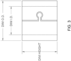
- FIG. 3 illustrates one example design for interlocking an outer end 110 with an inner end 120.
- the interlocked mechanical joint may have two separate cut off ends, allowing the flux core 130 to weep out and spread onto the substrates that are to be solder together.
- FIG. 3 depicts a "puzzle piece" interlock mechanism, other interlock mechanisms could be implemented.
- the flux core 130 may comprise between about 0.5 wt.% and 4.5 wt.% of the solder tube 100.
- the flux of flux core 130 may be a "no-clean" flux whose flux residue after reflow, may not need to be cleaned from the substrate to ensure reliability.
- the flux may be a water soluble flux or some other type of flux.
- Flux core 130 includes a thermochromic indicator that may be added to the flux prior to formation of solder tube 100.
- a thermochromic dye or pigment may be added to a flux before it is processed into the center of the solder alloy, and then formed into solder tube 100.
- the thermochromic indicator may come in a variety of different colors.
- the dye or pigment may be red, orange, pink, etc.
- the thermochromic indicator may be any suitable thermochromic component that, when heated, provides a visual indication that the solder alloy of solder tube 100 has reached a correct soldering temperature.
- the color of the thermochromic indicator coating the substrate may vanish at a desired reflow soldering temperature based on the chemistry of the thermochromic indicator component.
- a desired reflow soldering temperature based on the chemistry of the thermochromic indicator component.
- the thermochromic indicator and color may be selected depending on the melting properties (e.g., solidus and/or liquidus temperatures) of the solder alloy.
- the solder tube 100 may be comprised of any suitable solder alloy such as a tin-silver-copper (SAC) alloy, a Sn alloy, a SnAg alloy, a Bi alloy, an In alloy, or some other solder alloy.
- the solder tube 100 may be comprised of a single metal.
- the solder alloy or metal may make up 95.5 wt.% or greater of the solder tube.
- the solder tube may have a height to wall thickness ratio of greater than 3:1.
- the solder tube may have an inner diameter (ID) ranging from 0.762mm to 24.5mm and an outer diameter (OD) ranging from 1.27mm to 25.96 mm, where the ID And OD measurements are taken perpendicular to the center of the overlap joint, from side to side as depicted in FIG. 2B .
- the solder tube may have a height H ranging from 1.0mm to 12.25mm.
- the solder tube overlap joint may have a distance D ranging from 1.25mm to 2.03mm.
- the illustrated solder tube 100 may be used in a variety of applications, including cable splicing in wire harnesses and cable assemblies. For example, it may be placed within a plastic tube, wires may be inserted within tube 100, and then the assembly may be reflowed such that the solder creates an electrical connection while the plastic protects the connection from environmental hazards.
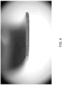
- FIG. 4 is a photograph illustrating a cross section of a solder tube after being cut apart. As illustrated, a flux core with a thermochromic indicator is embedded in the solder alloy and distributed substantially and uniformly. The thermochromic indicator in this example is colored red.
- the internal flux may have a higher level of flux by wt.% (e.g., up to about 4.5 wt.%, or in some cases even greater than 4.5 wt.%) as compared to the conventional exterior flux-coated design.
- the ID and OD dimensions of the tube may have tighter tolerances, along with eliminating the problem of flux obstructing the inner portion of the tube.
- thermochromic indicator While implementations of the disclosure have thus far been described in the context of solder tubes having an internal flux core including a thermochromic indicator, the techniques described herein could also be applied to a variety of other solder preforms that would benefit from having an embedded flux core with thermochromic indicator that flows out of the solder preform in a controlled manner to provide a visual indication during reflow soldering.
- an external coating of flux with thermochromic indicator on other preforms shapes chipping off of the external flux coating may be avoided. Additionally, the dust that may be created from shipping and handling such a product may be avoided.
- the flux coating may chip off easily, leaving exposed areas. Because solder tubes may be handled several times after flux coating and before final packaging, there is the potential for damages occurring on multiple occasions. Further, if solder tubes rub against each other during shipment, the flux coating may turn into a flux powder/dust.
- FIGs. 5A-5B illustrate a solder washer 500.
- FIG. 5A shows a perspective view of solder washer 500.
- FIG. 5B shows a cross-sectional view of solder washer 500.
- solder washer 500 has a flat, circularly shaped alloy body, with a central hole, an ID section 530, and an OD section 540.
- solder washer 500 may have a height to wall thickness ratio of less than or equal to three (e.g., a height to wall thickness ratio of 3:1).
- solder washer 500 has a circular body shape with a central circular hole in this example, in other implementations its body and/or central hole may have some other elliptical shape or a non-elliptical shape.
- the washer hole and/or body may have a rectangular shape.
- solder alloy body 510 Embedded in solder alloy body 510 is an internal flux core 520 with a thermochromic indicator.
- the solder alloy body 510 is open along the sidewall(s) of ID section 530 and the sidewall(s) of OD section 540.
- the internal flux core 520 flows out of solder washer 500 via the walls of ID section 530 and OD section 540 during reflow soldering.
- the side wall(s) of only one of the ID section 530 or OD section 540 is/are open.
- solder washer 500 may have a thickness of between 0.1mm and 3.937mm; an ID between 0.381mm and 12.7mm; and an OD between 0.762mm and 19.05mm.
- Solder washer 500 may be manufactured using a stamping die.
- solder washer 500 may be stamped or cut from a solder.
- a preform with internal flux core 520 may be formed, and the washer 500 may be cut or stamped from the preform. This process of cutting out the washer may expose the internal flux core 520 via the side walls of ID section 530 and OD section 540.
- a solder ribbon with internal flux core 520 may be formed, and the solder washer 500 may be stamped from the solder ribbon.
- solder washer having an overlapping joint similar to solder tube 100 may be formed in a similar manner to how solder tube 100 is formed.
- FIGs. 6A-6B illustrate a solder disc 600.
- FIG. 6A shows a perspective view of solder disc 600.
- FIG. 6B shows a cross-sectional view of solder disc 600.
- solder disc 600 has a flat, circularly shaped alloy body 610 and outer section 620.
- solder disc 600 may have a height to wall thickness ratio of less than or equal to three (e.g., a height to wall thickness ratio of 3:1).
- solder disc 600 has a circular body shape in this example, in other implementations its body may have some other elliptical shape.
- solder alloy body 610 Embedded in solder alloy body 610 is an internal flux core 630 with a thermochromic indicator.
- the solder alloy body 610 is open along the sidewall(s) of outer section 620.
- the internal flux core 630 flows out of solder disc 600 via the sidewall(s) of outer section 620 during reflow soldering.
- the side wall(s) of solder disc 600 may be open along its entire diameter. In other implementations, the side wall(s) of solder disc may be open along a portion or portions of the disc's diameter.
- solder disc 600 may have a thickness between 0.1mm and 3.937mm, and an OD between 0.762mm and 19.05mm.
- Solder disc 600 may be manufactured using a stamping die.
- solder disc 600 may be stamped or cut from a solder.
- a preform with internal flux core 630 may be formed, and the solder disc 600 may be cut or stamped from the preform. This process of cutting out the disc may expose the internal flux core 630 via the side walls of outer section 620.
- a solder ribbon with internal flux core 630 may be formed, and the solder disc 600 may be stamped from the solder ribbon.
- FIGs. 7A-7B illustrate a solder ribbon segment 700.
- FIG. 7A shows a top perspective view of solder ribbon segment 700.
- FIG. 7B shows a cross-sectional view of the solder ribbon segment 700.
- solder ribbon segment 700 has a solder alloy body 710 that is flat and rectangular in shape.
- solder ribbon segment 700 may have a square shape.
- solder alloy body 710 Embedded in solder alloy body 710 is an internal flux core 720 with a thermochromic indicator.
- the solder alloy body 710 is open along an end 730 along its height.
- the internal flux core 720 flows out of solder ribbon segment 700 via end 730 during reflow soldering.
- the opening at end 730 may be formed by cutting solder ribbon segment 700 from a solder ribbon.
- solder ribbon segment 700 may be cut from a spool of solder ribbon.
- solder ribbon segment 700 may be open along both ends such that the internal flux core 720 flows out of both ends during reflow soldering.
- solder ribbon segment 700 may have a thickness between 0.1mm and 3.937mm.
- solder preform described herein may be assume an irregular shape to tailor it to a specific application.
- FIGs. 8A-8B illustrate an irregularly-shaped solder preform 800.
- FIG. 8A shows a top perspective view of solder preform 800.
- FIG. 8B shows a cross-sectional view of the solder preform 800.
- solder preform 800 has an irregularly-shaped, flat solder alloy body 810.
- Embedded in solder alloy body 810 is an internal flux core 820 with a thermochromic indicator. During reflow soldering, the internal flux core 820 flows out of an opening of the solder preform 800.
- the flux core with thermochromic indicator of the solder preforms described herein may comprise between about 0.5 wt.% and 4.5 wt.% of the solder preform. In some implementations, the flux core may comprise between about 3.0 wt.% and 4.5 wt.% of the solder preform. In other implementations, the flux core may comprise greater than 4.5 wt.% of the solder preform, ribbon, or wire.
- the flux core may be a "no-clean" flux whose flux residue after reflow, may not need to be cleaned from the substrate to ensure reliability. Alternatively the flux may be a water soluble flux or some other type of flux.
- the solder alloy body of the solder preforms described herein may comprise any suitable solder alloy such as a tin-silver-copper (SAC) alloy, a Sn alloy, a SnAg alloy, a Bi alloy, an In alloy, or some other solder alloy.
- the solder alloy body may be comprised of a single metal. The solder alloy body may make up 95.5 wt.% or greater of the solder preform, ribbon, or wire.
- the solder preforms described herein may be configured to melt at a temperature between about 115°C and 370°C.
- the color of the thermochromic indicator of the flux core may be configured to vanish at a temperature between about 120°C and 375°C.
- the thermochromic indicator may be configured to become colorless once a peak reflow soldering temperature is reached.
- the peak reflow soldering temperature may be between about 115°C and 370°C.
Landscapes
- Engineering & Computer Science (AREA)
- Mechanical Engineering (AREA)
- Connections Effected By Soldering, Adhesion, Or Permanent Deformation (AREA)
- Electric Connection Of Electric Components To Printed Circuits (AREA)
Description
- The present disclosure generally relates to solder preforms, see claim 1.
- Solder tubes may be utilized for a variety of soldering applications, including radio systems, wire harnesses, as an EMI shield to ground termination, wire to wire splicing, etc. For example, soldering tubes may be used for terminating electrical joints within a heat shrink termination device. The ends of exposed electrical wiring may be placed within the solder tube and soldered together. The solder tube alloy preform may provide a precise, controlled amount of solder to hold the wires securely in place while an outer plastic sleeve may provide enclosed protection from the elements and further electrical contact.
- Solder tubes may be created using a progressive stamping die. For example, five to eight press strokes / cycles may be needed before a single tube is produced. Some conventional implementations of solder tubes provide a flux coating on the exterior of the solder tube to facilitate the soldering process. After the solder tube is made, it may be de-greased and then subjected to an exterior flux coating process. The exterior flux coating may be applied in the range of 0.5% to 3.0% by weight.
- To provide a visual verification that a reflow temperature for the solder has been reached, a thermochromic dye may be added to the exterior flux coating. During reflow soldering that melts the flux, when a correct reflow temperature is reached, the thermochromic dye will change color (e.g., become colorless). The color change of the thermochromic dye will show the operator that the solder alloy of the solder tube has reached a correct temperature to melt the solder alloy such that an acceptable solder joint may be formed.
FIG. 1 illustrates one such example of a thermochromic dye in a flux coating on a solder tube that is red prior to the reflow process /soldering.US4505421 A describes a heat-recoverable soldering device comprises a heat-recoverable member having a fusible solder insert and associated with the solder insert, a solder flux composition which undergoes a visible color change at a critical temperature. Solderable substrates are positioned within the device and heated until a critical temperature has been reached as indicated by a color change in the flux. The critical temperature depends on the material of the particular heat-recoverable member and the solder used. It is that temperature which is required to effect a solder joint between the substrates and recovery of the heat-recoverable member. -
EP203 8085 A1 (describing all the features of the preamble of claim 1) describes a wire for use in a brazing or soldering operation having an elongated body of a metallic material. The elongated body has an outer surface. A channel is formed along a length of the body. The channel has an opening. A flux solution is deposited within the channel and along the length of the body. The flux solution covers a portion of the outer surface. A portion of the flux solution is exposed through the opening in the channel. -
US6264062 B1 describes a solder preform with predisposed flux to be located adjacent to a gap formed between multiple solderable surfaces such that upon heating, the flux wicks into and prepares the solderable surfaces prior to the solder melting and wicking into the freshly prepared gap. -
WO2019070779 A1 describes a brazing wire including a first metal alloy wrap defining an encasing perimeter around a core and having a longitudinal seam extending over a length of the first metal alloy wrap, and a second metal alloy wrap disposed within the core of the first metal alloy wrap. The second metal alloy wrap defines an encasing perimeter around a core and has a longitudinal seam extending over a length of the second metal alloy wrap. The brazing wire further includes a corrosive flux material disposed within the core of the second metal alloy wrap. - Implementations of the disclosure are directed to solder preforms with an internal flux core including a thermochromic indicator.
- A solder preform according to the present invention is defined in claim 1.
- Further preferred embodiments of the present invention are defined in the appended claims. In some implementations, the second end is secured to the first end using an interlocking joint.
- In some implementations, each of the first opening and the second opening are cut along an entire height of the solder tube, wherein during reflow soldering, flux core flowing out of the first opening of the first end coats an inside of the solder tube and flux core flowing of the second opening of the second end coats an outside of the solder tube. In some implementations, the second end is secured to the first end using an interference fit with one or more stakes.
- In some implementations, the flux core of the solder tube comprises between 0.5 wt.% and 4.5 wt.% of the solder tube. In some implementations, the flux core of the solder tube comprises greater than 3.0 wt.% of the solder tube. In some implementations, the solder alloy comprises greater than or equal to 95.5 wt.% of the solder tube.
- In particular implementations, the solder tube has a height ranging from 1.0 mm to 12.25mm, an inner diameter ranging from 0.762mm to 24.5mm, and an outer diameter ranging from 1.27mm to 25.96mm, and wherein the second end overlaps the first end a distance ranging from 1.25mm to 2.03mm. In some implementations, the solder tube has a height to wall thickness of greater than 3:1.
- Other features and aspects of the present invention will become apparent from the following detailed description, taken in conjunction with the accompanying drawings, which illustrate, by way of example, the features in accordance with various embodiments. The summary is not intended to limit the scope of the invention, which is defined solely by the claims attached hereto.
- The technology disclosed herein, in accordance with one or more embodiments, is described in detail with reference to the following figures. The drawings are provided for purposes of illustration only and merely depict typical or example embodiments of the disclosed technology. These drawings are provided to facilitate the reader's understanding of the disclosed technology and shall not be considered limiting of the breadth, scope, or applicability thereof. It should be noted that for clarity and ease of illustration these drawings are not necessarily made to scale.
-
FIG. 1 shows an example of a thermochromic dye in a flux coating on a solder tube prior to reflow soldering. -
FIG. 2A shows a perspective view of a solder tube. -
FIG. 2B shows a side view of the solder tube ofFIG. 2A . -
FIG. 2C shows a cross-sectional top view of the solder tube ofFIG. 2A . -
FIG. 2D shows the top section ofFIG. 2C . -
FIG. 2E shows the bottom section ofFIG. 2C . -
FIG. 3 shows an example design for interlocking an outer end with an inner end of a solder tube. -
FIG. 4 shows a photograph illustrating a cross-section of a solder tube after being cut apart. -
FIG. 5A shows a solder washer. -
FIG. 5B shows a cross-sectional view of the solder washer ofFIG. 5A . -
FIG. 6A shows a solder disc. -
FIG. 6B shows a cross-sectional view of the solder disc ofFIG. 6A . -
FIG. 7A shows a solder ribbon segment. -
FIG. 7B shows a cross-sectional view of the solder ribbon segment ofFIG. 7A . -
FIG. 8A shows an irregularly shaped solder preform. -
FIG. 8B shows a cross-sectional view of the solder preform ofFIG. 8A . - The figures are not intended to be exhaustive or to limit the invention to the precise form disclosed. It should be understood that the invention can be practiced with modification and alteration, and that the disclosed technology be limited only by the appended claims.
- As used herein, the term "thermochromic indicator" refers to a thermochromic dye, thermochromic pigment, or other thermochromic component that may provide a visual indication of when a soldering temperature has been reached. For example, the thermochromic indicator may be a visible color at room temperature.
- According to the present invention, as the thermochromic indicator is heated at or above the alloy reflow temperature, the visible color may dissipate until the thermochromic indicator is colorless.
- As noted above, solder tubes coated with a solder flux including a thermochromic dye may facilitate the soldering process by providing a visual indication of when correct soldering temperatures have been reached. This design, however, may have a number of problems.
- First, if the amount of required flux is greater than about 2.0 wt%, it may become increasingly difficult to both obtain the required amount of flux by wt.% and uniformly coat the solder tube on its inner section and outer section.
- Second, during manufacture it may be very difficult to achieve a consistent inner diameter (ID) dimension across solder tubes because of the amount of flux that gets into the center of the tube. In some instances, the center of the tube may become plugged with flux.
- Third, the post flux curing step may present a variety of potential defects. The flux-coated surface of the tube may become tacky. Tubes may stick together and clump into one mass. The flux coating may chip off easily, leaving exposed areas. Because solder tubes may be handled several times after flux coating and before final packaging, there is the potential for damages occurring on multiple occasions. Further, if solder tubes rub against each other during shipment, the flux coating may turn into a flux powder/dust.
- Fourth, because of the dust that may be created from shipping the solder tubes and how they may be bowl fed, they may cause increased downtime of production lines because of the cleaning of the bowls needed due to the build-up of flux powder.
- In view of the foregoing issues, there is a need for an improved solder tube design. To this end, implementations of the disclosure are directed to solder tubes with an internal flux core including a thermochromic indicator. Additional implementations of the disclosure are directed to other solder preforms with an internal flux core including a thermochromic indicator.
-
FIGs. 2A-2E illustrate asolder tube 100.FIG. 2A shows a perspective view ofsolder tube 100,FIG. 2B shows a side view ofsolder tube 100, andFIG. 2C shows a cross sectional top view ofsolder tube 100.FIGs. 2D and 2E show the top and bottom sections ofFIG. 2C , respectively. As depicted,solder tube 100 has a cylindrically shaped solder alloy body, including an overlap joint with anouter end 110 circumferentially overlapping aninner end 120. In implementations, the body may have a circular cross section or an elliptical cross section. During formation, thesolder tube 100 may be cut off at each of theends 110 and 120 (e.g., heightwise along the solder tube). This allows aninternal flux core 130 with a thermochromic indicator to flow out of thesolder tube 100 throughouter end 110 andinner end 120 during reflow soldering. In other implementations, only one of theends flux core 130 flows through only one of the ends. - In some implementations, the
solder tube 100 may be perforated in one or more locations (e.g., either at the ends or some other location of the tube) to allow flux to flow out through the one or more perforations in addition to the ends during reflow soldering. The perforations may be of a suitable size and shape such that sufficient flux flows out of the perforations at a sufficient rate. The perforations may be formed after the solder alloy has been formed into a tube, or beforehand. In some implementations the solder alloy tube may be manufactured such that the flux only weeps out through perforations. For example, in such implementations, the solder tube may not have any overlapping ends (i.e., it is formed as a closed cylinder). - Each perforation may extend through the entire wall of the solder tube such that flux flows out of both an inner and outer side of the tube. Alternatively, the perforation may be formed such that flux only flows out through one of the inner side or outer side of the tube. The perforations may be suitably shaped (e.g., as an ellipse or polygon), deep, positioned, and/or numbered such that flux sufficiently covers the inner and/or outer surface of the tube and substrate during reflow soldering. For example, perforations may be circumferentially distributed throughout the solder tube (e.g., on the outer and/or inner side).
- Although in some implementations the solder tube could be manufactured such that the flux only weeps out through perforations (e.g., without having any overlapping ends), it has been observed in some instances that perforations by themselves may not be sufficient for allowing the flux to weep out onto the substrate. Without being bound to any particular theory, this may be attributed to the softness of the solder alloy metals, which may have a tendency to smear over the perforations, thus not allowing the flux to escape to the extent of design depicted in
FIGs. 2A-2E . - Referring again to
FIGs. 2A-2E ,flux core 130 flowing out ofinner end 120 may flow onto the soldered substrate through the interior of the tube whereas flux core flowing out ofouter end 110 may flow onto the soldered substrate through the exterior of the tube. During a reflow soldering process, theflux core 130 with the thermochromic indicator (e.g., dye or pigment) may weep out onto the substrate uniformly from cut ends 110 and 120. As thesolder tube 100 is heated and the flux begins to melt, the flux may uniformly flow out ofends - In the illustrated example, the overlapped joint is formed by staking in two locations 140 (e.g., through the center of the overlapping joint to be formed) to form an interference fit to prevent joint separation of the two cut ends 110 and 120. It should be appreciated that in other implementations the overlapped joint may be staked in one location or more than two locations to prevent joint separation. For example, the number of stakes may vary depending on the height of the
solder tube 100. Additionally, other methods may implemented as an alternative to or in addition to staking to prevent separation of or otherwise hold the overlapped joint in place. For example, in some implementations the overlapped joint may be created by spot soldering. As another example,FIG. 3 illustrates one example design for interlocking anouter end 110 with aninner end 120. The interlocked mechanical joint may have two separate cut off ends, allowing theflux core 130 to weep out and spread onto the substrates that are to be solder together. AlthoughFIG. 3 depicts a "puzzle piece" interlock mechanism, other interlock mechanisms could be implemented. - In implementations, the
flux core 130 may comprise between about 0.5 wt.% and 4.5 wt.% of thesolder tube 100. The flux offlux core 130 may be a "no-clean" flux whose flux residue after reflow, may not need to be cleaned from the substrate to ensure reliability. Alternatively the flux may be a water soluble flux or some other type of flux. -
Flux core 130 includes a thermochromic indicator that may be added to the flux prior to formation ofsolder tube 100. For example, a thermochromic dye or pigment may be added to a flux before it is processed into the center of the solder alloy, and then formed intosolder tube 100. Depending on its chemical makeup, the thermochromic indicator may come in a variety of different colors. For example, the dye or pigment may be red, orange, pink, etc. The thermochromic indicator may be any suitable thermochromic component that, when heated, provides a visual indication that the solder alloy ofsolder tube 100 has reached a correct soldering temperature. During reflow soldering, the color of the thermochromic indicator coating the substrate may vanish at a desired reflow soldering temperature based on the chemistry of the thermochromic indicator component. When color is found to be non-existent during reflow (e.g., melting) of the alloy, this may provide an indication that the solder alloy has maintained a suitable temperature for a sufficient amount of time. As should be appreciated, the thermochromic indicator and color may be selected depending on the melting properties (e.g., solidus and/or liquidus temperatures) of the solder alloy. - The
solder tube 100 may be comprised of any suitable solder alloy such as a tin-silver-copper (SAC) alloy, a Sn alloy, a SnAg alloy, a Bi alloy, an In alloy, or some other solder alloy. In some implementations, thesolder tube 100 may be comprised of a single metal. The solder alloy or metal may make up 95.5 wt.% or greater of the solder tube. The solder tube may have a height to wall thickness ratio of greater than 3:1. - In implementations, the solder tube may have an inner diameter (ID) ranging from 0.762mm to 24.5mm and an outer diameter (OD) ranging from 1.27mm to 25.96 mm, where the ID And OD measurements are taken perpendicular to the center of the overlap joint, from side to side as depicted in
FIG. 2B . In implementations, the solder tube may have a height H ranging from 1.0mm to 12.25mm. In implementations, the solder tube overlap joint may have a distance D ranging from 1.25mm to 2.03mm. The illustratedsolder tube 100 may be used in a variety of applications, including cable splicing in wire harnesses and cable assemblies. For example, it may be placed within a plastic tube, wires may be inserted withintube 100, and then the assembly may be reflowed such that the solder creates an electrical connection while the plastic protects the connection from environmental hazards. -
FIG. 4 is a photograph illustrating a cross section of a solder tube after being cut apart. As illustrated, a flux core with a thermochromic indicator is embedded in the solder alloy and distributed substantially and uniformly. The thermochromic indicator in this example is colored red. - A variety of advantages may be achieved from the internal flux core solder tube design described herein. First, the internal flux may have a higher level of flux by wt.% (e.g., up to about 4.5 wt.%, or in some cases even greater than 4.5 wt.%) as compared to the conventional exterior flux-coated design. Second, because the flux is contained within the walls of the tube, the ID and OD dimensions of the tube may have tighter tolerances, along with eliminating the problem of flux obstructing the inner portion of the tube. Third, as no post flux curing step is needed, this may eliminate the aforementioned issues of having a tacky flux-coated surface, parts sticking together, the flux coating chipping off, and the coated flux turning into dust/powder from parts rubbing together during shipment. Moreover, by removing the dust/powder problem, production lines may no longer need to stop to clean bowls having a build-up of flux powder, thereby allowing them to operate for longer periods of time. These and other advantages that may be realized from the solder tube design described herein will be appreciated from the disclosure.
- While implementations of the disclosure have thus far been described in the context of solder tubes having an internal flux core including a thermochromic indicator, the techniques described herein could also be applied to a variety of other solder preforms that would benefit from having an embedded flux core with thermochromic indicator that flows out of the solder preform in a controlled manner to provide a visual indication during reflow soldering. By foregoing an external coating of flux with thermochromic indicator on other preforms shapes, chipping off of the external flux coating may be avoided. Additionally, the dust that may be created from shipping and handling such a product may be avoided.
- The flux coating may chip off easily, leaving exposed areas. Because solder tubes may be handled several times after flux coating and before final packaging, there is the potential for damages occurring on multiple occasions. Further, if solder tubes rub against each other during shipment, the flux coating may turn into a flux powder/dust.
- For example,
FIGs. 5A-5B illustrate asolder washer 500.FIG. 5A shows a perspective view ofsolder washer 500.FIG. 5B shows a cross-sectional view ofsolder washer 500. As depicted,solder washer 500 has a flat, circularly shaped alloy body, with a central hole, anID section 530, and anOD section 540. In some implementations,solder washer 500 may have a height to wall thickness ratio of less than or equal to three (e.g., a height to wall thickness ratio of 3:1). Althoughsolder washer 500 has a circular body shape with a central circular hole in this example, in other implementations its body and/or central hole may have some other elliptical shape or a non-elliptical shape. For example, the washer hole and/or body may have a rectangular shape. - Embedded in
solder alloy body 510 is aninternal flux core 520 with a thermochromic indicator. In this example, thesolder alloy body 510 is open along the sidewall(s) ofID section 530 and the sidewall(s) ofOD section 540. As such, theinternal flux core 520 flows out ofsolder washer 500 via the walls ofID section 530 andOD section 540 during reflow soldering. In other implementations, the side wall(s) of only one of theID section 530 orOD section 540 is/are open. - In some implementations,
solder washer 500 may have a thickness of between 0.1mm and 3.937mm; an ID between 0.381mm and 12.7mm; and an OD between 0.762mm and 19.05mm.Solder washer 500 may be manufactured using a stamping die. In some implementations,solder washer 500 may be stamped or cut from a solder. For example, a preform withinternal flux core 520 may be formed, and thewasher 500 may be cut or stamped from the preform. This process of cutting out the washer may expose theinternal flux core 520 via the side walls ofID section 530 andOD section 540. For example, a solder ribbon withinternal flux core 520 may be formed, and thesolder washer 500 may be stamped from the solder ribbon. - In other implementations, a solder washer having an overlapping joint similar to
solder tube 100 may be formed in a similar manner to howsolder tube 100 is formed. -
FIGs. 6A-6B illustrate asolder disc 600.FIG. 6A shows a perspective view ofsolder disc 600.FIG. 6B shows a cross-sectional view ofsolder disc 600. As depicted,solder disc 600 has a flat, circularly shapedalloy body 610 andouter section 620. In some implementations,solder disc 600 may have a height to wall thickness ratio of less than or equal to three (e.g., a height to wall thickness ratio of 3:1). Althoughsolder disc 600 has a circular body shape in this example, in other implementations its body may have some other elliptical shape. - Embedded in
solder alloy body 610 is aninternal flux core 630 with a thermochromic indicator. In this example, thesolder alloy body 610 is open along the sidewall(s) ofouter section 620. As such, theinternal flux core 630 flows out ofsolder disc 600 via the sidewall(s) ofouter section 620 during reflow soldering. In some implementations, the side wall(s) ofsolder disc 600 may be open along its entire diameter. In other implementations, the side wall(s) of solder disc may be open along a portion or portions of the disc's diameter. - In some implementations,
solder disc 600 may have a thickness between 0.1mm and 3.937mm, and an OD between 0.762mm and 19.05mm.Solder disc 600 may be manufactured using a stamping die. In some implementations,solder disc 600 may be stamped or cut from a solder. For example, a preform withinternal flux core 630 may be formed, and thesolder disc 600 may be cut or stamped from the preform. This process of cutting out the disc may expose theinternal flux core 630 via the side walls ofouter section 620. For example, a solder ribbon withinternal flux core 630 may be formed, and thesolder disc 600 may be stamped from the solder ribbon. - In some implementations, a solder preform formed by cutting a segment of solder ribbon may be used.
FIGs. 7A-7B illustrate asolder ribbon segment 700.FIG. 7A shows a top perspective view ofsolder ribbon segment 700.FIG. 7B shows a cross-sectional view of thesolder ribbon segment 700. As depicted,solder ribbon segment 700 has asolder alloy body 710 that is flat and rectangular in shape. In some implementations,solder ribbon segment 700 may have a square shape. - Embedded in
solder alloy body 710 is aninternal flux core 720 with a thermochromic indicator. In this example, thesolder alloy body 710 is open along anend 730 along its height. As such, theinternal flux core 720 flows out ofsolder ribbon segment 700 viaend 730 during reflow soldering. In implementations, the opening atend 730 may be formed by cuttingsolder ribbon segment 700 from a solder ribbon. For example,solder ribbon segment 700 may be cut from a spool of solder ribbon. In some implementations,solder ribbon segment 700 may be open along both ends such that theinternal flux core 720 flows out of both ends during reflow soldering. In some implementations,solder ribbon segment 700 may have a thickness between 0.1mm and 3.937mm. - In some implementations, the solder preform described herein may be assume an irregular shape to tailor it to a specific application.
FIGs. 8A-8B illustrate an irregularly-shapedsolder preform 800.FIG. 8A shows a top perspective view ofsolder preform 800.FIG. 8B shows a cross-sectional view of thesolder preform 800. As depicted,solder preform 800 has an irregularly-shaped, flatsolder alloy body 810. Embedded insolder alloy body 810 is aninternal flux core 820 with a thermochromic indicator. During reflow soldering, theinternal flux core 820 flows out of an opening of thesolder preform 800. - In some implementations, the flux core with thermochromic indicator of the solder preforms described herein may comprise between about 0.5 wt.% and 4.5 wt.% of the solder preform. In some implementations, the flux core may comprise between about 3.0 wt.% and 4.5 wt.% of the solder preform. In other implementations, the flux core may comprise greater than 4.5 wt.% of the solder preform, ribbon, or wire. The flux core may be a "no-clean" flux whose flux residue after reflow, may not need to be cleaned from the substrate to ensure reliability. Alternatively the flux may be a water soluble flux or some other type of flux.
- In some implementations, the solder alloy body of the solder preforms described herein may comprise any suitable solder alloy such as a tin-silver-copper (SAC) alloy, a Sn alloy, a SnAg alloy, a Bi alloy, an In alloy, or some other solder alloy. In some implementations, the solder alloy body may be comprised of a single metal. The solder alloy body may make up 95.5 wt.% or greater of the solder preform, ribbon, or wire.
- In some implementations, the solder preforms described herein may be configured to melt at a temperature between about 115°C and 370°C. The color of the thermochromic indicator of the flux core may be configured to vanish at a temperature between about 120°C and 375°C. The thermochromic indicator may be configured to become colorless once a peak reflow soldering temperature is reached. The peak reflow soldering temperature may be between about 115°C and 370°C.
- While various embodiments of the disclosed technology have been described above, it should be understood that they have been presented by way of example only, and not of limitation. Likewise, the various diagrams may depict an example architectural or other configuration for the disclosed technology, which is done to aid in understanding the features and functionality that can be included in the disclosed technology. The disclosed technology is not restricted to the illustrated example architectures or configurations, but the desired features can be implemented using a variety of alternative architectures and configurations. Indeed, it will be apparent to one of skill in the art how alternative functional, logical or physical partitioning and configurations can be implemented to implement the desired features of the technology disclosed herein. Also, a multitude of different constituent module names other than those depicted herein can be applied to the various partitions. Additionally, with regard to flow diagrams, operational descriptions and method claims, the order in which the steps are presented herein shall not mandate that various embodiments be implemented to perform the recited functionality in the same order unless the context dictates otherwise.
Claims (12)
- A solder preform (100) comprising:either the preform being in shape of a solder tube, the tube comprising a cylindrically shaped solder alloy body, the solder alloy body comprising a first end (120), a second end (110), and at least one opening located at the first end or the second end, the second end circumferentially overlapping, or interlocking with, the first end;or the preform being in the shape of a solder washer with a central hole, the washer comprising a solder alloy body with an inner diameter sidewall and an outer diameter sidewall, and at least one opening located at the inner diameter sidewall or the outer diameter sidewall;the solder preform being characterised by the following:
a flux core (130) embedded in the solder alloy body, the flux core comprising a thermochromic indicator, such that during reflow soldering, the flux core comprising the thermochromic indicator is configured to flow out of the at least one opening of the solder alloy, and the thermochromic indicator is configured to become colorless at or above a reflow temperature of the solder alloy, - The solder preform of claim 1, wherein the solder preform is in the shape of a solder tube.
- The solder preform of claim 2, wherein the at least one opening comprises a first opening and a second opening, the first opening located at the first end, and the second opening located at the second end, such that during reflow soldering, the flux core comprising the thermochromic indicator flows out of the first opening and the second opening.
- The solder preform of claim 3, wherein each of the first opening and the second opening are cut along an entire height of the solder tube, such that during reflow soldering, flux core flowing out of the first opening of the first end coats an inside of the solder tube and flux core flowing of the second opening of the second end coats an outside of the solder tube.
- The solder preform of claim 3, wherein the second end is secured to the first end using an interference fit with one or more stakes; and optionally wherein the flux core of the solder tube comprises greater than 3.0 wt.% of the solder tube.
- The solder preform of claim 3, wherein the flux core of the solder tube comprises between 0.5 wt.% and 4.5 wt.% of the solder tube; and optionally wherein the solder alloy comprises greater than or equal to 95.5 wt.% of the solder tube.
- The solder preform of claim 3, wherein the solder tube has a height ranging from 1.0 mm to 12.25mm, an inner diameter ranging from 0.762mm to 24.5mm, and an outer diameter ranging from 1.27mm to 25.96mm, and
wherein the second end overlaps the first end a distance ranging from 1.25mm to 2.03mm, or wherein the solder tube has a height to wall thickness of greater than 3:1. - The solder preform of claim 2, wherein the second end is secured to the first end using an interlocking joint.
- The solder preform of claim 1, wherein the solder preform is in the shape of a solder washer.
- The solder preform of claim 9, wherein the flux core of the solder preform comprises between about 0.5 wt. % and 4.5 wt. % of the solder preform.
- The solder preform of claim 10, wherein the flux core of the solder preform comprises between about 3.0 wt.% and 4.5 wt% of the solder preform.
- The solder preform of claim 9, wherein the flux core of the solder preform comprises greater than 4.5 wt% of the solder preform.
Applications Claiming Priority (2)
| Application Number | Priority Date | Filing Date | Title |
|---|---|---|---|
| US201962840931P | 2019-04-30 | 2019-04-30 | |
| PCT/US2020/030536 WO2020223394A1 (en) | 2019-04-30 | 2020-04-29 | Solder preform with internal flux core including thermochromic indicator |
Publications (4)
| Publication Number | Publication Date |
|---|---|
| EP3962689A1 EP3962689A1 (en) | 2022-03-09 |
| EP3962689C0 EP3962689C0 (en) | 2024-11-06 |
| EP3962689B1 true EP3962689B1 (en) | 2024-11-06 |
| EP3962689B8 EP3962689B8 (en) | 2025-03-19 |
Family
ID=70775526
Family Applications (1)
| Application Number | Title | Priority Date | Filing Date |
|---|---|---|---|
| EP20727044.8A Active EP3962689B8 (en) | 2019-04-30 | 2020-04-29 | Solder preform with internal flux core including thermochromic indicator |
Country Status (5)
| Country | Link |
|---|---|
| US (3) | US11602808B2 (en) |
| EP (1) | EP3962689B8 (en) |
| HU (1) | HUE069097T2 (en) |
| PL (1) | PL3962689T3 (en) |
| WO (1) | WO2020223394A1 (en) |
Families Citing this family (2)
| Publication number | Priority date | Publication date | Assignee | Title |
|---|---|---|---|---|
| WO2020223394A1 (en) * | 2019-04-30 | 2020-11-05 | Indium Corporation | Solder preform with internal flux core including thermochromic indicator |
| CN113579554A (en) * | 2021-08-13 | 2021-11-02 | 深圳市福摩索金属制品有限公司 | High-performance preformed soldering lug and welding method thereof |
Family Cites Families (32)
| Publication number | Priority date | Publication date | Assignee | Title |
|---|---|---|---|---|
| US2503564A (en) * | 1944-09-02 | 1950-04-11 | Bell Telephone Labor Inc | Soldering composition |
| US2945464A (en) * | 1954-01-22 | 1960-07-19 | Tomoda Jichio | Jacketed soldering strip |
| US3087238A (en) * | 1958-10-06 | 1963-04-30 | Ralph B Nottingham | Tell-tale indicator for heat processes and method of using it |
| DE1206282B (en) * | 1963-12-04 | 1965-12-02 | Dr Guenther Laubmeyer | Flux-filled solder |
| US4137369A (en) * | 1977-05-03 | 1979-01-30 | Wik-It Electronics Corporation | Visual dye indicator of solder wicking action in metal coated copper braid |
| CA1166941A (en) * | 1978-12-22 | 1984-05-08 | Francis J.A.M.C. De Blauwe | Thermochromic composition |
| US4667869A (en) * | 1981-10-05 | 1987-05-26 | Raychem Corporation | Soldering methods and devices |
| US4563224A (en) * | 1981-10-05 | 1986-01-07 | Raychem Corporation | Soldering flux containing a temperature sensitive chemically reactive colorant |
| US4505421A (en) * | 1981-10-05 | 1985-03-19 | Raychem Corporation | Soldering methods and devices |
| US4809901A (en) * | 1981-10-05 | 1989-03-07 | Raychem Corporation | Soldering methods and devices |
| DE3569216D1 (en) * | 1984-07-18 | 1989-05-11 | Raychem Pontoise Sa | Solder connector device |
| US5143273A (en) * | 1986-11-20 | 1992-09-01 | Methode Electronics, Inc. | Attachment of solder buttons to elongated conductor |
| US5452840A (en) * | 1990-05-15 | 1995-09-26 | Hughes Aircraft Company | Water-soluble soldering flux |
| US5303824A (en) * | 1992-12-04 | 1994-04-19 | International Business Machines Corporations | Solder preform carrier and use |
| US5781846A (en) * | 1993-02-25 | 1998-07-14 | Jossick; James L. | Flux cored brazing composition |
| US5789068A (en) * | 1995-06-29 | 1998-08-04 | Fry's Metals, Inc. | Preformed solder parts coated with parylene in a thickness effective to exhibit predetermined interference colors |
| NL1001809C2 (en) * | 1995-12-04 | 1997-06-06 | Witmetaal B V | Solder sleeve and a method of forming it. |
| US5887779A (en) * | 1997-04-25 | 1999-03-30 | Phoenix Logistics, Inc. | Solder sleeve having improved heat transfer characteristics and method therefor |
| US6264062B1 (en) | 1999-06-09 | 2001-07-24 | Craig D. Lack | Solder preforms with predisposed flux for plumbing applications |
| US6830632B1 (en) * | 2002-07-24 | 2004-12-14 | Lucas Milhaupt, Inc. | Flux cored preforms for brazing |
| US7017795B2 (en) * | 2003-11-03 | 2006-03-28 | Indium Corporation Of America | Solder pastes for providing high elasticity, low rigidity solder joints |
| US10081852B2 (en) * | 2005-09-15 | 2018-09-25 | Senju Metal Industry Co., Ltd. | Solder preform and a process for its manufacture |
| MX2008006132A (en) * | 2005-11-10 | 2008-10-23 | Wolverine Tube Inc | Brazing material with continuous length layer of elastomer containing a flux. |
| WO2007140236A1 (en) | 2006-05-25 | 2007-12-06 | Bellman-Melcor Development, Llc | Filler metal with flux for brazing and soldering and method of making and using same |
| DE202007002140U1 (en) * | 2007-02-14 | 2007-04-05 | Stannol Gmbh | Solder for use in soft soldering |
| WO2011053506A1 (en) * | 2009-10-26 | 2011-05-05 | Lucas-Milhaupt, Inc. | Low silver, low nickel brazing material |
| JP2015033714A (en) * | 2013-08-09 | 2015-02-19 | 富士電機株式会社 | Flux for flux cored solder and flux solder |
| US9731383B2 (en) * | 2014-07-09 | 2017-08-15 | Bellman-Melcor Development, Llc | Filler metal with flux for brazing and soldering and method of using same |
| US10086477B2 (en) * | 2014-11-24 | 2018-10-02 | Lincoln Global, Inc. | Flux-cored brazing preform |
| US20180361518A1 (en) * | 2017-06-16 | 2018-12-20 | Indium Corporation | Solder ribbon with embedded mesh for improved reliability of semiconductor die to substrate attachment |
| EP3523085A1 (en) | 2017-10-03 | 2019-08-14 | Lucas-Milhaupt, Inc. | Corrosive flux cored wire and method of manufacture |
| WO2020223394A1 (en) * | 2019-04-30 | 2020-11-05 | Indium Corporation | Solder preform with internal flux core including thermochromic indicator |
-
2020
- 2020-04-29 WO PCT/US2020/030536 patent/WO2020223394A1/en not_active Ceased
- 2020-04-29 PL PL20727044.8T patent/PL3962689T3/en unknown
- 2020-04-29 US US16/862,299 patent/US11602808B2/en active Active
- 2020-04-29 HU HUE20727044A patent/HUE069097T2/en unknown
- 2020-04-29 EP EP20727044.8A patent/EP3962689B8/en active Active
-
2023
- 2023-02-16 US US18/110,766 patent/US12521821B2/en active Active
-
2025
- 2025-11-26 US US19/402,594 patent/US20260077436A1/en active Pending
Also Published As
| Publication number | Publication date |
|---|---|
| EP3962689A1 (en) | 2022-03-09 |
| EP3962689C0 (en) | 2024-11-06 |
| HUE069097T2 (en) | 2025-02-28 |
| US20200346307A1 (en) | 2020-11-05 |
| WO2020223394A1 (en) | 2020-11-05 |
| US20260077436A1 (en) | 2026-03-19 |
| US20230191541A1 (en) | 2023-06-22 |
| PL3962689T3 (en) | 2024-12-16 |
| US11602808B2 (en) | 2023-03-14 |
| US12521821B2 (en) | 2026-01-13 |
| EP3962689B8 (en) | 2025-03-19 |
Similar Documents
| Publication | Publication Date | Title |
|---|---|---|
| US20260077436A1 (en) | Solder preform with internal flux core including thermochromic indicator | |
| DE60203839T2 (en) | Surface mount miniature fuse | |
| US20110123824A1 (en) | Brazing material | |
| CA1337030C (en) | Solder connector device | |
| DE3118943A1 (en) | LOW-SAFETY | |
| EP2327504A1 (en) | Brazing material | |
| EP0001921B1 (en) | Tinned copper braid for solder removing and method of manufacturing the same | |
| NZ195642A (en) | Cartridge fuse:wire on insulator strip within barrel | |
| CN101489713A (en) | Filler metal with flux for brazing and soldering and method of making and using same | |
| DE3928308A1 (en) | METHOD FOR SOLDERING A TUBULAR AND A COUNTERPIECE | |
| JP2015533016A (en) | Cable connector connection terminal core, and cable connector connection terminal core and cable connection method | |
| US20120006881A1 (en) | Flux Cored Preforms for Brazing | |
| EP0122826A1 (en) | Easily connectible and directly solderable multi-wired electrical conductor | |
| DE10355043A1 (en) | Method for fastening an electrical conductor to a surface element, and hot runner element, in particular for a plastic injection device | |
| DE3120572A1 (en) | METHOD FOR ATTACHING A PREFORMED LOETRING TO A LID OF A CONTAINER | |
| DE112006003928T5 (en) | Small size surface mount fuse and method of making same | |
| DE2943603A1 (en) | SOLDER INSERT | |
| EP2996200A1 (en) | Connecting element | |
| DE8910519U1 (en) | Solder wire as hard solder | |
| DE3037587C2 (en) | Stranded wire consisting of several individual wires and the process for their manufacture | |
| DE102017113837B3 (en) | METHOD FOR SEALING A JOINT AREA OF AN ELECTRICAL CONNECTION ASSEMBLY AND ELECTRICAL CONNECTION ASSEMBLY | |
| JP4711064B2 (en) | Ring varistor and manufacturing method thereof | |
| EP0193854B1 (en) | Electrical resistance having a negative temperature coefficient, and production process therefor | |
| EP4443457B1 (en) | Method for assembling a temperature-dependent switch | |
| JP6373640B2 (en) | Manufacturing method of cylindrical current fuse |
Legal Events
| Date | Code | Title | Description |
|---|---|---|---|
| STAA | Information on the status of an ep patent application or granted ep patent |
Free format text: STATUS: UNKNOWN |
|
| STAA | Information on the status of an ep patent application or granted ep patent |
Free format text: STATUS: THE INTERNATIONAL PUBLICATION HAS BEEN MADE |
|
| PUAI | Public reference made under article 153(3) epc to a published international application that has entered the european phase |
Free format text: ORIGINAL CODE: 0009012 |
|
| STAA | Information on the status of an ep patent application or granted ep patent |
Free format text: STATUS: REQUEST FOR EXAMINATION WAS MADE |
|
| 17P | Request for examination filed |
Effective date: 20211028 |
|
| AK | Designated contracting states |
Kind code of ref document: A1 Designated state(s): AL AT BE BG CH CY CZ DE DK EE ES FI FR GB GR HR HU IE IS IT LI LT LU LV MC MK MT NL NO PL PT RO RS SE SI SK SM TR |
|
| DAV | Request for validation of the european patent (deleted) | ||
| DAX | Request for extension of the european patent (deleted) | ||
| P01 | Opt-out of the competence of the unified patent court (upc) registered |
Effective date: 20230602 |
|
| GRAP | Despatch of communication of intention to grant a patent |
Free format text: ORIGINAL CODE: EPIDOSNIGR1 |
|
| STAA | Information on the status of an ep patent application or granted ep patent |
Free format text: STATUS: GRANT OF PATENT IS INTENDED |
|
| INTG | Intention to grant announced |
Effective date: 20240627 |
|
| GRAS | Grant fee paid |
Free format text: ORIGINAL CODE: EPIDOSNIGR3 |
|
| GRAA | (expected) grant |
Free format text: ORIGINAL CODE: 0009210 |
|
| STAA | Information on the status of an ep patent application or granted ep patent |
Free format text: STATUS: THE PATENT HAS BEEN GRANTED |
|
| AK | Designated contracting states |
Kind code of ref document: B1 Designated state(s): AL AT BE BG CH CY CZ DE DK EE ES FI FR GB GR HR HU IE IS IT LI LT LU LV MC MK MT NL NO PL PT RO RS SE SI SK SM TR |
|
| REG | Reference to a national code |
Ref country code: GB Ref legal event code: FG4D |
|
| REG | Reference to a national code |
Ref country code: CH Ref legal event code: EP |
|
| REG | Reference to a national code |
Ref country code: DE Ref legal event code: R096 Ref document number: 602020040802 Country of ref document: DE |
|
| REG | Reference to a national code |
Ref country code: IE Ref legal event code: FG4D |
|
| U01 | Request for unitary effect filed |
Effective date: 20241107 |
|
| P04 | Withdrawal of opt-out of the competence of the unified patent court (upc) registered |
Free format text: CASE NUMBER: APP_60849/2024 Effective date: 20241112 |
|
| U07 | Unitary effect registered |
Designated state(s): AT BE BG DE DK EE FI FR IT LT LU LV MT NL PT RO SE SI Effective date: 20241115 |
|
| GRAT | Correction requested after decision to grant or after decision to maintain patent in amended form |
Free format text: ORIGINAL CODE: EPIDOSNCDEC |
|
| REG | Reference to a national code |
Ref country code: CH Ref legal event code: PK Free format text: BERICHTIGUNGEN |
|
| REG | Reference to a national code |
Ref country code: CH Ref legal event code: PK Free format text: BERICHTIGUNGEN Ref country code: CH Ref legal event code: PK Free format text: BERICHTIGUNG B8 Ref country code: HU Ref legal event code: AG4A Ref document number: E069097 Country of ref document: HU |
|
| RIN2 | Information on inventor provided after grant (corrected) |
Inventor name: HEVEL, JAMES, B. Inventor name: LANZA JR., ANTHONY D. Inventor name: MERRITT, CRAIG K. |
|
| RIN2 | Information on inventor provided after grant (corrected) |
Inventor name: HEVEL, JAMES B. Inventor name: LANZA JR., ANTHONY D. Inventor name: MERRITT, CRAIG K. |
|
| PG25 | Lapsed in a contracting state [announced via postgrant information from national office to epo] |
Ref country code: IS Free format text: LAPSE BECAUSE OF FAILURE TO SUBMIT A TRANSLATION OF THE DESCRIPTION OR TO PAY THE FEE WITHIN THE PRESCRIBED TIME-LIMIT Effective date: 20250306 Ref country code: HR Free format text: LAPSE BECAUSE OF FAILURE TO SUBMIT A TRANSLATION OF THE DESCRIPTION OR TO PAY THE FEE WITHIN THE PRESCRIBED TIME-LIMIT Effective date: 20241106 |
|
| PG25 | Lapsed in a contracting state [announced via postgrant information from national office to epo] |
Ref country code: ES Free format text: LAPSE BECAUSE OF FAILURE TO SUBMIT A TRANSLATION OF THE DESCRIPTION OR TO PAY THE FEE WITHIN THE PRESCRIBED TIME-LIMIT Effective date: 20241106 |
|
| PG25 | Lapsed in a contracting state [announced via postgrant information from national office to epo] |
Ref country code: NO Free format text: LAPSE BECAUSE OF FAILURE TO SUBMIT A TRANSLATION OF THE DESCRIPTION OR TO PAY THE FEE WITHIN THE PRESCRIBED TIME-LIMIT Effective date: 20250206 |
|
| PG25 | Lapsed in a contracting state [announced via postgrant information from national office to epo] |
Ref country code: GR Free format text: LAPSE BECAUSE OF FAILURE TO SUBMIT A TRANSLATION OF THE DESCRIPTION OR TO PAY THE FEE WITHIN THE PRESCRIBED TIME-LIMIT Effective date: 20250207 |
|
| PG25 | Lapsed in a contracting state [announced via postgrant information from national office to epo] |
Ref country code: RS Free format text: LAPSE BECAUSE OF FAILURE TO SUBMIT A TRANSLATION OF THE DESCRIPTION OR TO PAY THE FEE WITHIN THE PRESCRIBED TIME-LIMIT Effective date: 20250206 |
|
| U20 | Renewal fee for the european patent with unitary effect paid |
Year of fee payment: 6 Effective date: 20250407 |
|
| PG25 | Lapsed in a contracting state [announced via postgrant information from national office to epo] |
Ref country code: SM Free format text: LAPSE BECAUSE OF FAILURE TO SUBMIT A TRANSLATION OF THE DESCRIPTION OR TO PAY THE FEE WITHIN THE PRESCRIBED TIME-LIMIT Effective date: 20241106 |
|
| PGFP | Annual fee paid to national office [announced via postgrant information from national office to epo] |
Ref country code: HU Payment date: 20250415 Year of fee payment: 6 |
|
| PG25 | Lapsed in a contracting state [announced via postgrant information from national office to epo] |
Ref country code: SK Free format text: LAPSE BECAUSE OF FAILURE TO SUBMIT A TRANSLATION OF THE DESCRIPTION OR TO PAY THE FEE WITHIN THE PRESCRIBED TIME-LIMIT Effective date: 20241106 |
|
| PG25 | Lapsed in a contracting state [announced via postgrant information from national office to epo] |
Ref country code: CZ Free format text: LAPSE BECAUSE OF FAILURE TO SUBMIT A TRANSLATION OF THE DESCRIPTION OR TO PAY THE FEE WITHIN THE PRESCRIBED TIME-LIMIT Effective date: 20241106 |
|
| PLBE | No opposition filed within time limit |
Free format text: ORIGINAL CODE: 0009261 |
|
| STAA | Information on the status of an ep patent application or granted ep patent |
Free format text: STATUS: NO OPPOSITION FILED WITHIN TIME LIMIT |
|
| 26N | No opposition filed |
Effective date: 20250807 |
|
| REG | Reference to a national code |
Ref country code: CH Ref legal event code: H13 Free format text: ST27 STATUS EVENT CODE: U-0-0-H10-H13 (AS PROVIDED BY THE NATIONAL OFFICE) Effective date: 20251125 |
|
| PG25 | Lapsed in a contracting state [announced via postgrant information from national office to epo] |
Ref country code: MC Free format text: LAPSE BECAUSE OF FAILURE TO SUBMIT A TRANSLATION OF THE DESCRIPTION OR TO PAY THE FEE WITHIN THE PRESCRIBED TIME-LIMIT Effective date: 20241106 |
|
| PG25 | Lapsed in a contracting state [announced via postgrant information from national office to epo] |
Ref country code: CH Free format text: LAPSE BECAUSE OF NON-PAYMENT OF DUE FEES Effective date: 20250430 |
|
| PGFP | Annual fee paid to national office [announced via postgrant information from national office to epo] |
Ref country code: GB Payment date: 20260310 Year of fee payment: 7 |
|
| PG25 | Lapsed in a contracting state [announced via postgrant information from national office to epo] |
Ref country code: IE Free format text: LAPSE BECAUSE OF NON-PAYMENT OF DUE FEES Effective date: 20250429 |
|
| U20 | Renewal fee for the european patent with unitary effect paid |
Year of fee payment: 7 Effective date: 20260310 |
|
| PGFP | Annual fee paid to national office [announced via postgrant information from national office to epo] |
Ref country code: PL Payment date: 20260206 Year of fee payment: 7 |