EP3962403B1 - Orthodontische klammer mit vorgespanntem ligationselement - Google Patents
Orthodontische klammer mit vorgespanntem ligationselement Download PDFInfo
- Publication number
- EP3962403B1 EP3962403B1 EP20799549.9A EP20799549A EP3962403B1 EP 3962403 B1 EP3962403 B1 EP 3962403B1 EP 20799549 A EP20799549 A EP 20799549A EP 3962403 B1 EP3962403 B1 EP 3962403B1
- Authority
- EP
- European Patent Office
- Prior art keywords
- bracket
- projection
- ligating
- bracket body
- orthodontic bracket
- Prior art date
- Legal status (The legal status is an assumption and is not a legal conclusion. Google has not performed a legal analysis and makes no representation as to the accuracy of the status listed.)
- Active
Links
Images





Classifications
-
- A—HUMAN NECESSITIES
- A61—MEDICAL OR VETERINARY SCIENCE; HYGIENE
- A61C—DENTISTRY; APPARATUS OR METHODS FOR ORAL OR DENTAL HYGIENE
- A61C7/00—Orthodontics, i.e. obtaining or maintaining the desired position of teeth, e.g. by straightening, evening, regulating, separating, or by correcting malocclusions
- A61C7/12—Brackets; Arch wires; Combinations thereof; Accessories therefor
- A61C7/20—Arch wires
-
- A—HUMAN NECESSITIES
- A61—MEDICAL OR VETERINARY SCIENCE; HYGIENE
- A61C—DENTISTRY; APPARATUS OR METHODS FOR ORAL OR DENTAL HYGIENE
- A61C7/00—Orthodontics, i.e. obtaining or maintaining the desired position of teeth, e.g. by straightening, evening, regulating, separating, or by correcting malocclusions
- A61C7/12—Brackets; Arch wires; Combinations thereof; Accessories therefor
- A61C7/28—Securing arch wire to bracket
- A61C7/287—Sliding locks
-
- A—HUMAN NECESSITIES
- A61—MEDICAL OR VETERINARY SCIENCE; HYGIENE
- A61C—DENTISTRY; APPARATUS OR METHODS FOR ORAL OR DENTAL HYGIENE
- A61C7/00—Orthodontics, i.e. obtaining or maintaining the desired position of teeth, e.g. by straightening, evening, regulating, separating, or by correcting malocclusions
- A61C7/12—Brackets; Arch wires; Combinations thereof; Accessories therefor
- A61C7/28—Securing arch wire to bracket
- A61C7/30—Securing arch wire to bracket by resilient means; Dispensers therefor
Definitions
- This application generally relates to self-ligating orthodontic brackets, and more specifically, to such brackets having a biased ligating member designed for improved overall performance.
- Orthodontic treatment typically involves orthodontic devices designed to apply mechanical forces to a patient's teeth to urge improperly positioned teeth into a correct alignment.
- One form of orthodontic treatment includes the use of self-ligating orthodontic brackets, where a single bracket is adhered to each individual tooth in a subset of teeth with a bonding material or other adhesive. Once the brackets are in position on the teeth, an archwire is inserted through a slot formed on each of the brackets. In this configuration, tightening of the archwire applies pressure on the brackets, which in turn, urge movement of the teeth into a desired position and orientation.
- self-ligating brackets may include a ligating door or slide with a spring or other biasing element to help retain the archwire in position within the slot.
- the ligating slide is movable between closed and open positions to allow insertion and retention of the archwire within an archwire slot of the bracket.
- KR 101693239 B1 , EP 3170472 A2 , and US 2010178629 A1 all disclose examples of orthodontic brackets comprising a ligating slide that is moveable between closed and open positions and a biasing element such as a spring or pin. In such designs, the biasing element provides a retention force that holds the ligating slide in either the open or closed position for improved use.
- the ligating slide is typically cycled (e.g., opened and closed) approximately 6 to 10 times during the course of orthodontic treatment.
- conventional self-ligating brackets are designed to optimize the retention force of the spring for short life-cycles.
- the number of cycles for specific treatments may increase due to additional archwire adjustments, additional archwire changes, or auxiliary treatment mechanics.
- the present inventors have identified a need for an improved design of an orthodontic bracket for providing an effective and consistent retention force for a significant number of opening/closing cycles to ensure optimum performance for a variety of uses and circumstances.
- Such a design maximizes the number of open and close cycles the ligating slide and biasing element can tolerate without experiencing a dramatic reduction in the retention force that holds the ligating slide in either the open or closed position, thereby minimizing long-term performance issues of the orthodontic bracket.
- the improved design secures the ligating slide against the orthodontic bracket to prevent complete disengagement from the bracket. Additional aspects and advantages will be apparent from the following detailed description of example embodiments, which proceeds with reference to the accompanying drawings.
- this section describes various embodiments of an orthodontic bracket system and its detailed construction and operation.
- reference to "one embodiment,” “an embodiment,” or “some embodiments” means that a described feature, structure, or characteristic may be included in at least one embodiment of an orthodontic bracket.
- appearances of the phrases “in one embodiment,” “in an embodiment,” or “in some embodiments” in various places throughout this specification are not necessarily all referring to the same embodiment.
- the described features, structures, and characteristics may be combined in any suitable manner in one or more embodiments. In view of the disclosure herein, those skilled in the art will recognize that the various embodiments can be practiced without one or more of the specific details or with other methods, components, materials, or the like.
- FIG. 1 illustrates an example embodiment of an orthodontic self-ligating bracket 10 including a bracket body 12 with a sliding door 26 designed to move relative to the bracket body 12 between a closed position and an open position.
- the following description refers to the bracket 10 as being attached to a labial surface of a tooth on an upper jaw of the patient.
- the bracket body 12 illustrated in FIG. 1 when the bracket body 12 is mounted to the tooth in the patient's upper jaw, the bracket body 12 has a lingual side 14 (see also FIG. 3 ), a labial side 16, an occlusal side 18, a gingival side 20, a mesial side 22, and a distal side 24.
- bracket 10 Terms such as labial, lingual, mesial, distal, occlusal, and gingival used to describe the bracket 10 in this specification are relative to this frame of reference. It should be understood, however, that the embodiments of the disclosed subject matter are not limited to the chosen reference frame and descriptive terms, as the orthodontic bracket 10 may be used on other teeth and in other orientations within the oral cavity. For example, the bracket 10 may also be located on an anterior tooth in the lower jaw or maxilla and be within the scope of the disclosed subject matter. Those having ordinary skill in the art will recognize that the descriptive terms used herein may not directly apply when there is a change in the frame of reference.
- the bracket 10 includes a bracket body 12 mountable to a tooth via a base structure 28 (see FIG. 3 ) on the lingual side 14 of the bracket body 12.
- the base structure 28 may include a series of grooves or ridges for receiving an adhesive or other bonding material to provide a solid connection with the tooth and prevent dislodging.
- the bracket body 12 further includes an archwire slot 30 extending across the bracket body 12 from a first side to a second side generally in a mesial-distal direction, such as from the mesial side 22 to the distal side 24.
- the archwire slot 30 includes a generally planar base surface 32 extending across the length of the slot 30 and opposing side walls 34, 36 extending upwardly from the base surface 32 in the labial direction.
- the side walls 34, 36 are perpendicular to the base surface 32 to form a generally rectilinear archwire slot 30 (e.g., a slot having a generally rectangular or square shape), the archwire slot 30 having open ends formed along the labial side 16, and along the mesial and distal sides 22, 24, respectively, of the bracket body 12.
- the bracket body 12 further includes a sliding ligating member or door 26 arranged on the labial side 16 of the bracket body 12 for retaining an archwire (not shown) within the archwire slot 30.
- the sliding door 26 includes a base 38 and a pair of side rails 40, 42 designed to be slidably received within a corresponding pair of guides 44, 46 formed on the bracket body 12. Once the sliding door 26 is inserted into position within the bracket body 12, the side rails 40, 42 and guides 44, 46 work together to restrict movement of the sliding door 26 to the gingival-occlusal direction when the sliding door 26 is opened or closed. When the sliding door 26 is in the closed position, the archwire is urged downwardly into the archwire slot 30 to apply pressure to the bracket body 12 and the patient's teeth to produce the desired tooth movement.
- the bracket body 12 further houses a resilient biasing member 48 designed to impart force upon the sliding door 26 to help maintain the sliding door 26 either in a closed position or an open position as further described below with particular reference to FIGS. 5-8 .
- the biasing member 48 extends generally upright along the lingual-labial direction, with a lower portion of the biasing member 48 inserted into and retained within a seat 50 formed along a labial surface 52 of the bracket body 12, the seat 50 opening along the labial surface 52 and extending downwardly through the bracket body 12 from the labial surface 52 to the base surface 28 on the lingual side 14 of the bracket body 12 (see FIG. 3 ).
- the seat 50 opens onto the base surface 28 as illustrated in FIG. 3 , but in other embodiments, the seat 50 may be closed off along the base surface 28. In configuration where the seat 50 opens onto the base surface 28, an adhesive may be applied from the lingual side 14 or from the labial surface 52 to adhesively attach the lower portion of the biasing member 48 to the bracket body 12.
- the seat 50 may include one or more side walls 54 each having a ridged profile that extends toward a central portion of the seat 50, the side walls 54 designed to interfere with and firmly grip the biasing member 48 within the seat 50 to further secure the biasing member 48 in position. Further details of the biasing member 48 are provided below.
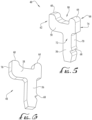
- FIGS. 5-8 collectively illustrate features of the biasing member 48 and its interaction with the sliding door 26 to retain the sliding door 26 in either the open or closed conditions as desired.
- FIGS. 5 and 6 illustrate an example embodiment of the biasing member 48 in accordance with one embodiment.
- the biasing member 48 is arranged in a generally T-shaped configuration with a generally upright stem 56 and a cross member 58 supported by and disposed generally orthogonal to the stem 56.
- the cross member 58 may instead be skewed or angled relative to the upright stem 56 to vary the retention force as needed.
- the cross member 58 includes a first projection 60 extending upwardly from the cross member 58 at a first end 62 thereof, and a second projection 64 extending upwardly from the cross member 58 along a second end 66 thereof.
- the projections 60, 64 are arranged along respective axes that are generally parallel to the axis of the stem 56, and extend along the lingual-labial direction, the projections 60, 64 being offset from one another to define a gap or opening 90 therebetween.
- the stem 56 may further include one or more ribs 68 formed along a side surface 70 extending between a first (front) surface 72 and an opposite second (rear) surface 74. As noted previously, the ribs 68 may interact with the one or more side walls 54 to help secure and retain the biasing member 48 in position within the seat 50 on the bracket body 12 (see FIG. 4 ).
- the cross member 58 further includes a leading edge surface 76 extending between the first and second surfaces 72, 74 of the biasing member 48.
- the leading edge surface 76 defines the perimeter shape of the biasing member 48, whereby the overall shape of the biasing member 48 is contained within the first and second surfaces 72, 74 as illustrated in FIGS. 5-6 .
- the stem 56, cross member 58, and projections 60, 62 are formed as unitary, integral components of the biasing member 48.
- the biasing member 48 may be made of nickel titanium and etched, laser cut, machined (e.g., electrical discharge machining) or otherwise manufactured from a substantially planar stock or sheet to create a biasing member 48 with the first surface 72 and the opposite second surface 74 being substantially planar and the leading edge surface 76 extending therebetween.
- the biasing member 48 may be made of any other suitable material.
- FIGS. 7-8 are each cross-section views of the assembled bracket 10 illustrated in the closed and open condition, respectively.
- the sliding door 26 includes a slot 77 formed on an underside thereof, the slot 77 extending from a front end of the sliding door 26 and opening onto a back end thereof.
- the sliding door 26 further includes a ridge 80 formed within the slot 77 (see FIG. 3 ), where the ridge 80 interacts with the resilient member 48 as further described in detail below.
- the ridge 80 may include a ramped guiding surface 82 formed along one end, the guiding surface 82 leading to a curved tip or end 84 formed at an apex of the ridge 80.
- a stop surface 86 extends from the curved end 84 toward the underside of the sliding door 26.
- a channel 78 is formed therebetween, the channel 78 incorporating the slot 77 of the sliding door 26 and extending from the side wall 34 (which forms one wall of the archwire slot 30) and opening along the occlusal side 18 of the bracket body 12. While the channel 78 and the slot 77 are illustrated as being opened along their respective back ends, in other embodiments, one or both of the slot 77 and channel 78 may instead be closed along the occlusal side 18 of the bracket body 12 if desired.
- the biasing member 48 is positioned within the seat 50 formed on the bracket body 12.
- the biasing member 48 is secured therein, a portion of the stem 56 extends from the seat 50 and into the channel 78, where the stem 56 extends generally upright along the lingual-labial direction.
- the entirety of the cross member 58 is positioned within the channel 78 and is arranged generally parallel to the gingival-occlusal sliding direction of the sliding door 26, with the leading edge surface 76 (see FIG. 6 ) positioned within the slot 77 and generally perpendicular to the topographic surface of the sliding door 26.
- the projection 60 of the resilient biasing member 48 rests against the ridge 80 along a beginning portion of the ramped guiding surface 82.
- the resilient biasing member 48 via the cross member 58 and the projection 60, collectively create a biasing force sufficient to resist unwanted movement of the sliding door 26 toward the occlusal side 18 of the bracket body 12 and thereby maintain the sliding door 26 in the closed position.
- a tool (not shown) may be inserted into a recessed region 88 formed along the labial surface of the sliding door 26.
- the ramped surface 82 of the ridge 80 slides against the projection 60 of the resilient biasing member 48.
- the cross member 58 of the resilient biasing member 48 deflects forwardly and downwardly toward the gingival side 20 in an arcuate path about the stem 56.
- the curved end 84 of the ridge 80 passes over and beyond the projection 60 of the resilient biasing member 48.
- the ridge 80 is positioned within the gap or opening 90 formed between the first and second projections 60, 64 (see FIG. 8 ).
- the force imparted against resilient biasing member 48 is released, thereby urging the resilient biasing member 48 to return to its upright and unbiased position, with the projection 60 being positioned within a pocket 92 formed adjacent a forward end of the sliding door 26 between a front wall 94 on an underside of the sliding door 26 and the ridge 80.
- an upper portion of the projection 60 abuts the front wall 94 and an underside of the sliding door 26 to ensure that the door 26 is securely retained against the bracket body 12 when in the open position.
- the projection 60 may abut one or both of the front wall 94 and the stop surface 86 of the ridge 80 when the projection 60 is in the pocket 92.
- the projections 60, 64 of the resilient biasing member 48 help maintain the sliding door 26 in the open position to access the archwire slot 30 (e.g., to position an archwire or to adjust an existing archwire), and also to ensure that the sliding door 26 is not inadvertently opened too far such that it may be decoupled from the bracket body 12.
- the second projection 64 of the resilient biasing member 48 may be eliminated since the projection 60 and pocket 92 may cooperate to limit the rearward movement of the sliding door 26 (as illustrated in FIGS. 10-11 ).
- the resistive force created by the projection 60 against the ridge 80 must be overcome.
- the ridge 80 moves within the opening 90 toward the projection 60.
- the cross member 58 is deflected forwardly and downwardly toward the gingival side 20 in an arcuate path about the stem 56.
- the cross member 58 continues deflecting until the ridge 80 moves beyond the projection 60, at which point, the cross member 58 deflects along the arcuate path to its original upright and unbiased position (as shown in FIG. 7 ).
- FIGS. 9A-9G illustrate various views of another embodiment for a resilient biasing element 148 that may be incorporated into the orthodontic bracket of FIG. 1 in place of the resilient biasing element 48 of FIGS. 5-6 .
- the resilient biasing element 148 includes many of the same components as the resilient biasing element 48 of FIGS. 5-6 , but notably eliminates the second (rear) projection 64 for a more streamlined design.
- the following passages provide more information regarding the biasing element 148, but in some instances, may only briefly describe certain features of the resilient biasing element 148 with the understanding that like features of the resilient biasing elements 48, 148 will operate similarly unless noted otherwise. Discussion of such features is omitted to avoid repetition.
- the resilient biasing element 148 is arranged in a generally inverted-L shape with a generally upright stem 156 and a cross member 158 supported by and disposed generally orthogonal to the stem 156.
- the cross member 158 may instead be skewed or angled relative to the upright stem 156 to vary the retention force as needed.
- the cross member 158 includes a first projection 160 extending upwardly from the cross member 158 at a first end 162 thereof.
- the projection 160 is arranged along an axis that is generally parallel to the corresponding axis of the stem 156 and extends along the lingual-labial direction.
- the stem 156 may further include one or more ribs 168 for further securing the biasing element 148 in position within the bracket body 1112 (see FIG. 10 ), the ribs 168 being formed along a side surface 170 extending between a first (front) surface 172 and an opposite second (rear) surface 174.
- the cross member 158 further includes a leading edge surface 176 extending between the first and second surfaces 172, 174 of the biasing member 148.
- the leading edge surface 176 defines the perimeter shape of the biasing member 148, whereby the overall shape of the biasing member 148 is contained within the first and second surfaces 172, 174 as illustrated in FIGS. 9A-9G .
- the stem 156, cross member 158, and projection 160 are formed as unitary, integral components of the biasing member 148 in a similar fashion as described previously with reference to biasing member 48.
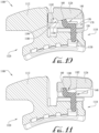
- FIGS. 10-11 are cross-section views of an assembled bracket 1100 illustrated in the closed and open condition, respectively.
- the bracket 1100 includes many of the same features and characteristics of the bracket 10 described with reference to FIGS. 7-8 . Accordingly, many of the features of the bracket 1100 and the door 1126 are not further described herein to avoid repetition, with the understanding that they share the same features as the bracket 10 and door 26 described previously. Accordingly, the following passages focus primarily on how the resilient biasing member 148 interacts with the bracket 1100 and door 1126.
- the resilient biasing member 148 is received in a seat 1150 of the bracket 1100, with the ribs 168 (and any adhesives that may be used) securing the biasing member 148 in position.
- the stem 156 extends generally upright along the lingual-labial direction and the cross member 158 is generally parallel to the gingival-occlusal sliding direction of the sliding door 1126.
- a portion of the stem 156 extends from the seat 1150 into the channel 178, and the entirety of the cross member 158 is positioned within the channel 178.
- the leading edge surface 176 (see FIG. 9B ) is positioned generally perpendicular to the topographic surface of the sliding door 1126 positioned within the channel 178.
- the projection 160 of the resilient biasing member 148 rests against a portion of the ramped guiding surface 1182 (see FIG. 11 ) of the ridge 1180 formed underneath the sliding door 1126.
- the resilient biasing member 148 via the cross member 158 and the projection 160, collectively create a biasing force sufficient to resist backward movement of the sliding door 1126 toward the occlusal side 1118 of the bracket body 1112 and thereby maintain the sliding door 1126 in the closed position.
- the ridge 1180 is positioned behind the first projection 160, with the projection 160 being positioned within a pocket 1192 (see FIG. 10 ) formed adjacent a forward end of the sliding door 1126 between a front wall 1194 on an underside of the sliding door 1126 and the ridge 1180.
- an upper portion of the projection 160 may abut one or both of the front wall 1194 and the ridge 1180 when the projection 160 is in the pocket 1192 in a similar fashion as discussed previously with reference to FIGS. 7-8 .
- the single projection 160 of the resilient biasing member 148 helps maintain the sliding door 1126 in the open position without requiring other contact points between the resilient biasing member 148 and the sliding door 1126.
- the resistive force created by the projection 160 against the ridge 1180 must be overcome.
- the ridge 1180 moves toward the projection 160.
- the cross member 158 is deflected forwardly and downwardly toward the gingival side 1120 in an arcuate path about the stem 156.
- the cross member 158 continues deflecting until the ridge 1180 moves beyond the projection 160, at which point, the cross member 158 deflects along the arcuate path to its original upright and unbiased position (as shown in FIG. 10 ).
- FIGS. 12-13 collectively illustrate features of another embodiment of an orthodontic bracket 100 (illustrated with the sliding door removed for convenience).
- the bracket 100 includes many of the same features as the orthodontic bracket 10 illustrated in FIG. 1 , although the bracket 100 is illustrated another embodiment without a hook on the gingival side (compare to FIG. 1 ). To avoid repetition, such common features of the orthodontic bracket 100 are not further discussed herein, with the understanding that the same or similar features of the orthodontic bracket 10 apply equally to the orthodontic bracket 100 of FIG. 12 .
- the orthodontic bracket 100 includes an archwire slot 102 extending across the bracket body 104 generally in a mesial-distal direction.
- the archwire slot 102 includes a base surface 106 and opposing side walls 108, 110 extending upwardly from the base surface 106 in the labial direction.
- the side walls 108, 110 are perpendicular to the base surface 106 to form a generally rectilinear archwire slot 102 having open ends along the peripheral sides as illustrated.
- the base surface 106 of the archwire slot 102 may further include a pair of recessed regions or channels 112, 114, where one channel 112 is formed between the base surface 106 and a bottom portion of the side wall 108, and the other channel 114 is formed between the base surface 106 and a bottom portion of the side wall 110.
- the channels 112, 114 each extend across the entire archwire slot 102 from the mesial to distal side of the bracket body 104, though in other embodiments, the channels 112, 114 may extend only partway along the length of the archwire slot 102.
- the channels 112, 114 may be formed as having generally curved or radiused profiles as illustrated in FIGS. 12-13 .
- the channels 112, 114 may have differently-shaped profiles, such as a more rectilinear-shaped profile. It should be understood that any suitable channel profile may be substituted without departing from the principles of the disclosed subject matter.
- the channels 112, 114 serve to improve the strength of the orthodontic bracket 100 and to minimize interference for a close fit between the archwire (not shown) and the archwire slot 102.
Landscapes
- Health & Medical Sciences (AREA)
- Oral & Maxillofacial Surgery (AREA)
- Dentistry (AREA)
- Epidemiology (AREA)
- Life Sciences & Earth Sciences (AREA)
- Animal Behavior & Ethology (AREA)
- General Health & Medical Sciences (AREA)
- Public Health (AREA)
- Veterinary Medicine (AREA)
- Dental Tools And Instruments Or Auxiliary Dental Instruments (AREA)
Claims (15)
- Kieferorthopädische Klammer (10, 1100) umfassend:einen Klammerkörper (12, 1112), der an einem Zahn angebracht werden kann, wobei der Klammerkörper einen Bogendrahtschlitz (30, 102) aufweist, der sich von einer ersten Seite des Klammerkörpers zu einer gegenüberliegenden zweiten Seite erstreckt, wobei der Bogendrahtschlitz so bemessen ist, dass er einen Bogendraht darin aufnehmen kann, wobei der Klammerkörper ferner einen Sitz (50, 1150) einschließt, der entlang einer Labialfläche (52) des Klammerkörpers ausgebildet ist;ein Ligaturelement (26, 1126), das an dem Klammerkörper angebracht werden kann und zwischen einer geschlossenen Position und einer offenen Position bewegbar ist, wobei sich mindestens ein Abschnitt des Ligaturelements über den Bogendrahtschlitz erstreckt, um den Bogendraht innerhalb des Bogendrahtschlitzes zu halten, wenn sich das Ligaturelement in der geschlossenen Position befindet, und wobei das Ligaturelement von dem Bogendrahtschlitz versetzt ist, um Zugang zu dem Bogendraht zu bieten, wenn sich das Ligaturelement in der offenen Position befindet, wobei das Ligaturelement einen Schlitz (77), der entlang einer Unterseite davon ausgebildet ist, und einen Steg (80, 1180), der innerhalb des Schlitzes ausgebildet ist, einschließt, wobei der Steg ferner eine geneigte Führungsfläche (82, 1182) einschließt, wobei das Ligaturelement ferner eine Tasche (92, 1192) einschließt, die an der Unterseite des Ligaturelements ausgebildet ist;einen Kanal (78, 178), der zwischen dem Klammerkörper und dem Ligaturelement ausgebildet ist; undein elastisches Vorspannelement (48, 148), das einen unteren Abschnitt umfasst, der in den Sitz eingesetzt und darin gehalten wird, wobei das elastische Vorspannelement ferner einen Schaft (56, 156) umfasst, der sich von dem Sitz und in den Kanal erstreckt, wobei sich der Schaft im Allgemeinen aufrecht entlang einer lingual-labialen Richtung erstreckt und ein Querelement (58, 158) des elastischen Vorspannelements trägt, wobei das Querelement in dem Kanal positioniert ist, wobei das Querelement ferner einen Vorsprung (60, 160) einschließt, der sich von dem Querelement an einem ersten Ende (62, 162) desselben nach oben erstreckt, wobei der Vorsprung in der Tasche positioniert ist, wenn sich das Ligaturelement in der offenen Position befindet, und wobei der Vorsprung an dem Steg entlang eines Abschnitts der geneigten Führungsfläche ruht, um das Ligaturelement in der geschlossenen Position zu halten.
- Kieferorthopädische Klammer nach Anspruch 1, wobei sich das Querelement entlang eines bogenförmigen Pfads um den Schaft als Reaktion auf eine Kraft biegt, die durch das Ligaturelement gegen den Vorsprung ausgeübt wird, wenn das Ligaturelement zwischen der offenen Position und der geschlossenen Position bewegt wird.
- Kieferorthopädische Klammer nach Anspruch 1 oder 2, wobei das elastische Vorspannelement, einschließlich des Schafts, des Querträgers und des Vorsprungs, als ein einheitliches, integrales Bauteil ausgebildet ist.
- Kieferorthopädische Klammer nach Anspruch 3, wobei das elastische Vorspannelement aus einem Flachmaterial gebildet ist, sodass der Schaft und das Querelement jeweils eine erste ebene Fläche (72, 172) und eine gegenüberliegende zweite ebene Fläche (74, 174) einschließen, die durch eine sich dazwischen erstreckende Randfläche (70, 170) getrennt sind.
- Kieferorthopädische Klammer nach einem der vorstehenden Ansprüche, wobei das Querelement ferner einen zweiten Vorsprung (64) einschließt, der gegenüber dem Vorsprung um einen Spalt (90) versetzt ist, und wobei der Steg innerhalb des Spaltes zwischen dem Vorsprung und dem zweiten Vorsprung angeordnet ist, wenn sich das Ligaturelement in der offenen Position befindet.
- Kieferorthopädische Klammer nach einem der vorstehenden Ansprüche, wobei das elastische Vorspannelement ferner eine oder mehrere Rippen (68, 168) aufweist, die entlang eines ersten Abschnitts des Schafts angeordnet sind, wobei die eine oder mehreren Rippen den ersten Abschnitt des Schafts an dem Sitz des Klammerkörpers befestigen.
- Kieferorthopädische Klammer nach Anspruch 6, wobei der Sitz eine Öffnung einschließt, die entlang einer Unterseite des Klammerkörpers ausgebildet ist, und wobei sich der erste Abschnitt des Schafts durch die Öffnung erstreckt.
- Kieferorthopädische Klammer nach Anspruch 7, wobei sich der Sitz entlang der Labialfläche öffnet und sich von der Labialfläche nach unten durch den Klammerkörper zu einer Basisfläche (28) auf einer lingualen Seite (14) des Klammerkörpers erstreckt.
- Kieferorthopädische Klammer nach Anspruch 7 oder 8, wobei der erste Abschnitt des Schafts des elastischen Vorspannelementes mit dem Klammerkörper innerhalb des Sitzes durch Kleben verbunden ist.
- Kieferorthopädische Klammer nach einem der vorstehenden Ansprüche, wobei das elastische Vorspannelement ferner eine erste ebene Fläche (72, 172), eine gegenüberliegende zweite ebene Fläche (74, 174) und eine Randfläche (70, 170) aufweist, die sich zwischen der ersten ebenen Fläche und der zweiten ebenen Fläche erstreckt, wobei die Randfläche im Allgemeinen orthogonal zu einer Gleitrichtung des Ligaturelements angeordnet ist.
- Kieferorthopädische Klammer nach einem der vorstehenden Ansprüche, wobei sich das Ligaturelement in einer Bewegungsrichtung entlang einer ersten Achse zwischen der offenen Position und der geschlossenen Position bewegt, und wobei das Querelement innerhalb des Kanals entlang einer zweiten Achse parallel zur ersten Achse und zur Bewegungsrichtung des Ligaturelements angeordnet ist.
- Kieferorthopädische Klammer nach einem der vorstehenden Ansprüche, wobei der Drahtbogenschlitz eine erste Wand (108), eine gegenüberliegende zweite Wand (110) und eine sich dazwischen erstreckende Bodenfläche (106) einschließt, wobei der Klammerkörper ferner einen ersten Kanal (112), der zwischen der Bodenfläche und der ersten Wand angeordnet ist, und einen zweiten Kanal (114), der zwischen der Bodenfläche und der zweiten Wand angeordnet ist, einschließt.
- Kieferorthopädische Klammer nach Anspruch 12, wobei sich der erste Kanal und der zweite Kanal jeweils entlang des Drahtbogenschlitzes von der ersten Seite zu der gegenüberliegenden zweiten Seite des Klammerkörpers erstrecken.
- Kieferorthopädische Klammer nach einem der vorstehenden Ansprüche, wobei der Steg eine Anschlagfläche (86) einschließt und wobei der Vorsprung des elastischen Vorspannelements an der Anschlagfläche anliegt, um das Ligaturelement in der offenen Position zu halten.
- Kieferorthopädische Klammer nach Anspruch 14, wobei die Tasche zwischen der Anschlagfläche des Stegs und einer vorderen Wand (94, 1194) an der Unterseite des Ligaturelements ausgebildet ist.
Applications Claiming Priority (2)
| Application Number | Priority Date | Filing Date | Title |
|---|---|---|---|
| US201962842461P | 2019-05-02 | 2019-05-02 | |
| PCT/US2020/030864 WO2020223564A1 (en) | 2019-05-02 | 2020-04-30 | Orthodontic bracket with a biased ligating member |
Publications (3)
| Publication Number | Publication Date |
|---|---|
| EP3962403A1 EP3962403A1 (de) | 2022-03-09 |
| EP3962403A4 EP3962403A4 (de) | 2023-05-17 |
| EP3962403B1 true EP3962403B1 (de) | 2025-06-11 |
Family
ID=73016286
Family Applications (1)
| Application Number | Title | Priority Date | Filing Date |
|---|---|---|---|
| EP20799549.9A Active EP3962403B1 (de) | 2019-05-02 | 2020-04-30 | Orthodontische klammer mit vorgespanntem ligationselement |
Country Status (7)
| Country | Link |
|---|---|
| US (2) | US11633263B2 (de) |
| EP (1) | EP3962403B1 (de) |
| JP (1) | JP7611169B2 (de) |
| KR (1) | KR102879412B1 (de) |
| AU (1) | AU2020264490C1 (de) |
| CA (1) | CA3136681A1 (de) |
| WO (1) | WO2020223564A1 (de) |
Families Citing this family (2)
| Publication number | Priority date | Publication date | Assignee | Title |
|---|---|---|---|---|
| EP3962403B1 (de) * | 2019-05-02 | 2025-06-11 | World Class Technology Corporation | Orthodontische klammer mit vorgespanntem ligationselement |
| USD1045090S1 (en) * | 2021-10-29 | 2024-10-01 | Cheng-Hsiang Hung | Orthodontic bracket |
Family Cites Families (47)
| Publication number | Priority date | Publication date | Assignee | Title |
|---|---|---|---|---|
| US3549528A (en) * | 1964-04-23 | 1970-12-22 | Edward T Armstrong | Ozone sterilization process |
| US5015180A (en) | 1989-03-01 | 1991-05-14 | Minnesota Mining And Manufacturing Company | Dental article containing light-curable paste |
| US4978007A (en) | 1989-05-10 | 1990-12-18 | Minnesota Mining And Manufacturing Company | Packaging curable materials |
| US5044945A (en) * | 1990-05-22 | 1991-09-03 | Rmo, Inc. | Slot for orthodontic brackets and method |
| WO1993002631A1 (en) | 1991-08-02 | 1993-02-18 | Minnesota Mining And Manufacturing Company | Packaged dental article |
| US5322435A (en) | 1992-07-23 | 1994-06-21 | Pletcher Erwin Carroll | Orthodontic bracket |
| US5466151A (en) | 1993-04-08 | 1995-11-14 | Damon Family Limited Partnership | Spring-locked orthodontic bracket |
| US5366372A (en) | 1993-11-29 | 1994-11-22 | Minnesota Mining And Manufacturing Company | Method and apparatus for debonding ceramic orthodontic brackets |
| US6071118A (en) | 1998-02-17 | 2000-06-06 | Damon Family Limited Partnership | Self-ligating orthodontic bracket |
| US6183249B1 (en) | 1999-07-29 | 2001-02-06 | 3M Innovative Properties Company | Release substrate for adhesive precoated orthodontic appliances |
| US6582226B2 (en) | 1999-09-27 | 2003-06-24 | 3M Innovative Properties Company | Orthodontic appliance with self-releasing latch |
| US6302688B1 (en) | 1999-09-27 | 2001-10-16 | 3M Innovative Properties Company | Orthodontic appliance with self-releasing latch |
| US6506049B2 (en) | 2000-09-20 | 2003-01-14 | Augusta Developments Inc. | Orthodontic brackets and convertible buccal tubes |
| US6648638B2 (en) | 2001-12-28 | 2003-11-18 | 3M Innovative Properties Company | Orthodontic appliances including polycrystalline alumina-based ceramic material, kits, and methods |
| US7419375B2 (en) | 2002-08-19 | 2008-09-02 | Ormco Corporation | Aesthetic self-ligating orthodontic bracket |
| US7621743B2 (en) | 2002-11-26 | 2009-11-24 | Orthodontic Research And Development, S.L. | Orthodontic bracket |
| US7137812B2 (en) | 2003-10-03 | 2006-11-21 | 3M Innovative Properties Company | Apparatus for indirect bonding of orthodontic appliances and method of making the same |
| US7267545B2 (en) | 2005-01-11 | 2007-09-11 | Ormco Corporation | Self-ligating orthodontic bracket |
| US20090155734A1 (en) | 2006-04-19 | 2009-06-18 | Damon Dwight H | Orthodontic bracket |
| US7704072B2 (en) | 2006-04-19 | 2010-04-27 | Ormco Corporation | Orthodontic bracket |
| DE102006053215B4 (de) * | 2006-11-11 | 2009-10-22 | Bernhard Förster Gmbh | Selbstligierendes Bracket für die Orthodontie |
| US7726470B2 (en) | 2007-05-18 | 2010-06-01 | 3M Innovative Properties Company | Packaged orthodontic appliance and adhesive material |
| JP5215391B2 (ja) | 2007-06-28 | 2013-06-19 | オルムコ コーポレイション | 自己結紮式歯科矯正用ブラケットおよび該ブラケットの設置装置 |
| EP2008611A1 (de) | 2007-06-28 | 2008-12-31 | Ormco Corporation | Orthodontische Handwerkzeuge zur Verwendung mit einer selbstbindenden Zahnspange, Verfahren zur Verwendung derartiger orthodontischer Handwerkzeuge, selbstbindende Zahnspangen und Zahnspangensysteme |
| US8469704B2 (en) | 2007-06-28 | 2013-06-25 | Ormco Corporation | Self-ligating orthodontic bracket and devices for deploying same |
| JP2009164441A (ja) | 2008-01-09 | 2009-07-23 | Panasonic Corp | パターン形成方法 |
| US20090298003A1 (en) | 2008-05-28 | 2009-12-03 | Wei Yu-Chen | Self-Ligating Orthodontic Bracket |
| WO2010014518A2 (en) * | 2008-07-30 | 2010-02-04 | 3M Innovative Properties Company | Low profile self-ligating orthodontic appliance with clip |
| RU2011109216A (ru) | 2008-08-13 | 2012-09-20 | Ормко Корпорейшн (Us) | Эстетический ортодонтический брекет и способ его изоготовления |
| DE102008060820A1 (de) | 2008-12-05 | 2010-06-10 | Bernhard Förster Gmbh | Selbstligierendes Bracket für die Orthodontie |
| US20100285420A1 (en) | 2009-05-07 | 2010-11-11 | Ormco Corporation | Orthodontic bracket having a lingually biased closure member and associated method |
| DE102009049659B4 (de) | 2009-10-09 | 2014-10-30 | Bernhard Förster Gmbh | Selbstligierendes Bracket für die Orthodontie |
| US8029276B1 (en) | 2010-09-23 | 2011-10-04 | Robert Lokar | Self-ligating orthodontic bracket |
| US8998607B2 (en) | 2010-11-24 | 2015-04-07 | Ormco Corporation | Self-ligating orthodontic bracket having undercuts and related methods |
| US9271810B2 (en) | 2010-11-25 | 2016-03-01 | José Enrique Solano Reina | Orthodontic archwire bracket |
| US8568139B2 (en) * | 2011-11-23 | 2013-10-29 | Ronald M Roncone | Orthodontic bracket |
| TWM444154U (zh) | 2012-06-08 | 2013-01-01 | Micro Art Technology Co Ltd | 牙齒矯正器之自鎖定位裝置 |
| WO2014018095A1 (en) | 2012-07-23 | 2014-01-30 | 3M Innovative Properties Company | Self-ligating orthodontic bracket |
| US9364298B2 (en) | 2012-11-08 | 2016-06-14 | Ormco Corporation | Orthodontic bracket having a biased slide member |
| US9089386B2 (en) * | 2012-11-16 | 2015-07-28 | World Class Technology Corporation | Self-ligating bracket with sliding cover |
| US9744044B2 (en) | 2013-03-15 | 2017-08-29 | Mako Surgical Corp. | Unicondylar tibial knee implant |
| EP2783656B1 (de) | 2013-03-15 | 2017-06-28 | American Orthodontics Corporation | Selbstligierende Brackets |
| US9532853B2 (en) | 2013-03-15 | 2017-01-03 | Ormco Corporation | Self-ligating orthodontic bracket and method of using the same |
| US10085824B2 (en) | 2015-10-30 | 2018-10-02 | Ortho Organizers, Inc. | Self ligating orthodontic bracket |
| US10660729B2 (en) * | 2015-11-18 | 2020-05-26 | Alexandre Gallo Lopes | Self-ligating bracket with cantilever locking beam mechanism and other locking elements for ligating sliding members, and methods of making and use thereof |
| KR101693239B1 (ko) | 2016-07-06 | 2017-01-10 | 주식회사 페네시아 | 자가 결찰식 치열 교정용 브라켓 |
| EP3962403B1 (de) * | 2019-05-02 | 2025-06-11 | World Class Technology Corporation | Orthodontische klammer mit vorgespanntem ligationselement |
-
2020
- 2020-04-30 EP EP20799549.9A patent/EP3962403B1/de active Active
- 2020-04-30 CA CA3136681A patent/CA3136681A1/en active Pending
- 2020-04-30 US US16/863,726 patent/US11633263B2/en active Active
- 2020-04-30 WO PCT/US2020/030864 patent/WO2020223564A1/en not_active Ceased
- 2020-04-30 JP JP2021564823A patent/JP7611169B2/ja active Active
- 2020-04-30 AU AU2020264490A patent/AU2020264490C1/en active Active
- 2020-04-30 KR KR1020217036644A patent/KR102879412B1/ko active Active
-
2023
- 2023-04-24 US US18/306,104 patent/US12329604B2/en active Active
Also Published As
| Publication number | Publication date |
|---|---|
| KR20220002947A (ko) | 2022-01-07 |
| EP3962403A1 (de) | 2022-03-09 |
| JP7611169B2 (ja) | 2025-01-09 |
| US20230255730A1 (en) | 2023-08-17 |
| KR102879412B1 (ko) | 2025-10-30 |
| JP2022531340A (ja) | 2022-07-06 |
| WO2020223564A9 (en) | 2021-07-01 |
| EP3962403A4 (de) | 2023-05-17 |
| US11633263B2 (en) | 2023-04-25 |
| WO2020223564A1 (en) | 2020-11-05 |
| AU2020264490C1 (en) | 2025-05-15 |
| AU2020264490A1 (en) | 2021-11-25 |
| AU2020264490B2 (en) | 2025-02-13 |
| US20200345461A1 (en) | 2020-11-05 |
| US12329604B2 (en) | 2025-06-17 |
| CA3136681A1 (en) | 2020-11-05 |
Similar Documents
| Publication | Publication Date | Title |
|---|---|---|
| US10653505B2 (en) | Self-ligating bracket | |
| EP2269537B1 (de) | Orthodontische Spange mit einem lingual vorgespannten Verschlusselement | |
| US9867680B2 (en) | Orthodontic bracket | |
| US12329604B2 (en) | Orthodontic bracket with a biased ligating member | |
| US9585733B2 (en) | Orthodontic bracket with angled, curved shutter | |
| US9498303B2 (en) | Assembly formed by a self-ligating bracket and an elastic clip, for an orthodontic apparatus | |
| US9492246B2 (en) | Self-ligating orthodontic appliance and related methods | |
| US20070224569A1 (en) | Low profile self-ligating orthodontic brackets and methods of using such orthodontic brackets | |
| EP3600133B1 (de) | Selbstligierende spange mit einem ligaturelement | |
| US9393084B2 (en) | Clip-base-bracket assembly having a base for an orthodontic apparatus and orthodontic apparatus comprising same | |
| JP2003503084A (ja) | 自己−結紮する歯列矯正ブラケット | |
| EP2884939A1 (de) | Orthodontische klammer mit arretierblendenerweiterung | |
| CA2099730A1 (en) | Orthodontic bracket | |
| US11376102B2 (en) | Orthodontic bracket |
Legal Events
| Date | Code | Title | Description |
|---|---|---|---|
| STAA | Information on the status of an ep patent application or granted ep patent |
Free format text: STATUS: THE INTERNATIONAL PUBLICATION HAS BEEN MADE |
|
| PUAI | Public reference made under article 153(3) epc to a published international application that has entered the european phase |
Free format text: ORIGINAL CODE: 0009012 |
|
| STAA | Information on the status of an ep patent application or granted ep patent |
Free format text: STATUS: REQUEST FOR EXAMINATION WAS MADE |
|
| 17P | Request for examination filed |
Effective date: 20211022 |
|
| AK | Designated contracting states |
Kind code of ref document: A1 Designated state(s): AL AT BE BG CH CY CZ DE DK EE ES FI FR GB GR HR HU IE IS IT LI LT LU LV MC MK MT NL NO PL PT RO RS SE SI SK SM TR |
|
| DAV | Request for validation of the european patent (deleted) | ||
| DAX | Request for extension of the european patent (deleted) | ||
| A4 | Supplementary search report drawn up and despatched |
Effective date: 20230418 |
|
| RIC1 | Information provided on ipc code assigned before grant |
Ipc: A61C 7/30 20060101ALI20230412BHEP Ipc: A61C 7/28 20060101ALI20230412BHEP Ipc: A61C 7/00 20060101ALI20230412BHEP Ipc: A61C 7/12 20060101AFI20230412BHEP |
|
| GRAP | Despatch of communication of intention to grant a patent |
Free format text: ORIGINAL CODE: EPIDOSNIGR1 |
|
| STAA | Information on the status of an ep patent application or granted ep patent |
Free format text: STATUS: GRANT OF PATENT IS INTENDED |
|
| INTG | Intention to grant announced |
Effective date: 20240814 |
|
| GRAJ | Information related to disapproval of communication of intention to grant by the applicant or resumption of examination proceedings by the epo deleted |
Free format text: ORIGINAL CODE: EPIDOSDIGR1 |
|
| STAA | Information on the status of an ep patent application or granted ep patent |
Free format text: STATUS: REQUEST FOR EXAMINATION WAS MADE |
|
| GRAP | Despatch of communication of intention to grant a patent |
Free format text: ORIGINAL CODE: EPIDOSNIGR1 |
|
| STAA | Information on the status of an ep patent application or granted ep patent |
Free format text: STATUS: GRANT OF PATENT IS INTENDED |
|
| INTG | Intention to grant announced |
Effective date: 20250102 |
|
| GRAS | Grant fee paid |
Free format text: ORIGINAL CODE: EPIDOSNIGR3 |
|
| GRAA | (expected) grant |
Free format text: ORIGINAL CODE: 0009210 |
|
| STAA | Information on the status of an ep patent application or granted ep patent |
Free format text: STATUS: THE PATENT HAS BEEN GRANTED |
|
| AK | Designated contracting states |
Kind code of ref document: B1 Designated state(s): AL AT BE BG CH CY CZ DE DK EE ES FI FR GB GR HR HU IE IS IT LI LT LU LV MC MK MT NL NO PL PT RO RS SE SI SK SM TR |
|
| REG | Reference to a national code |
Ref country code: GB Ref legal event code: FG4D |
|
| REG | Reference to a national code |
Ref country code: CH Ref legal event code: EP |
|
| REG | Reference to a national code |
Ref country code: IE Ref legal event code: FG4D |
|
| REG | Reference to a national code |
Ref country code: DE Ref legal event code: R096 Ref document number: 602020052680 Country of ref document: DE |
|
| PG25 | Lapsed in a contracting state [announced via postgrant information from national office to epo] |
Ref country code: ES Free format text: LAPSE BECAUSE OF FAILURE TO SUBMIT A TRANSLATION OF THE DESCRIPTION OR TO PAY THE FEE WITHIN THE PRESCRIBED TIME-LIMIT Effective date: 20250611 Ref country code: FI Free format text: LAPSE BECAUSE OF FAILURE TO SUBMIT A TRANSLATION OF THE DESCRIPTION OR TO PAY THE FEE WITHIN THE PRESCRIBED TIME-LIMIT Effective date: 20250611 |
|
| REG | Reference to a national code |
Ref country code: LT Ref legal event code: MG9D |
|
| PG25 | Lapsed in a contracting state [announced via postgrant information from national office to epo] |
Ref country code: GR Free format text: LAPSE BECAUSE OF FAILURE TO SUBMIT A TRANSLATION OF THE DESCRIPTION OR TO PAY THE FEE WITHIN THE PRESCRIBED TIME-LIMIT Effective date: 20250912 Ref country code: NO Free format text: LAPSE BECAUSE OF FAILURE TO SUBMIT A TRANSLATION OF THE DESCRIPTION OR TO PAY THE FEE WITHIN THE PRESCRIBED TIME-LIMIT Effective date: 20250911 |
|
| REG | Reference to a national code |
Ref country code: NL Ref legal event code: MP Effective date: 20250611 |
|
| PG25 | Lapsed in a contracting state [announced via postgrant information from national office to epo] |
Ref country code: BG Free format text: LAPSE BECAUSE OF FAILURE TO SUBMIT A TRANSLATION OF THE DESCRIPTION OR TO PAY THE FEE WITHIN THE PRESCRIBED TIME-LIMIT Effective date: 20250611 |
|
| PG25 | Lapsed in a contracting state [announced via postgrant information from national office to epo] |
Ref country code: HR Free format text: LAPSE BECAUSE OF FAILURE TO SUBMIT A TRANSLATION OF THE DESCRIPTION OR TO PAY THE FEE WITHIN THE PRESCRIBED TIME-LIMIT Effective date: 20250611 |
|
| PG25 | Lapsed in a contracting state [announced via postgrant information from national office to epo] |
Ref country code: RS Free format text: LAPSE BECAUSE OF FAILURE TO SUBMIT A TRANSLATION OF THE DESCRIPTION OR TO PAY THE FEE WITHIN THE PRESCRIBED TIME-LIMIT Effective date: 20250911 |
|
| PG25 | Lapsed in a contracting state [announced via postgrant information from national office to epo] |
Ref country code: LV Free format text: LAPSE BECAUSE OF FAILURE TO SUBMIT A TRANSLATION OF THE DESCRIPTION OR TO PAY THE FEE WITHIN THE PRESCRIBED TIME-LIMIT Effective date: 20250611 |
|
| PG25 | Lapsed in a contracting state [announced via postgrant information from national office to epo] |
Ref country code: NL Free format text: LAPSE BECAUSE OF FAILURE TO SUBMIT A TRANSLATION OF THE DESCRIPTION OR TO PAY THE FEE WITHIN THE PRESCRIBED TIME-LIMIT Effective date: 20250611 |
|
| PG25 | Lapsed in a contracting state [announced via postgrant information from national office to epo] |
Ref country code: PT Free format text: LAPSE BECAUSE OF FAILURE TO SUBMIT A TRANSLATION OF THE DESCRIPTION OR TO PAY THE FEE WITHIN THE PRESCRIBED TIME-LIMIT Effective date: 20251013 |
|
| REG | Reference to a national code |
Ref country code: AT Ref legal event code: MK05 Ref document number: 1801790 Country of ref document: AT Kind code of ref document: T Effective date: 20250611 |
|
| PG25 | Lapsed in a contracting state [announced via postgrant information from national office to epo] |
Ref country code: IS Free format text: LAPSE BECAUSE OF FAILURE TO SUBMIT A TRANSLATION OF THE DESCRIPTION OR TO PAY THE FEE WITHIN THE PRESCRIBED TIME-LIMIT Effective date: 20251011 |
|
| PG25 | Lapsed in a contracting state [announced via postgrant information from national office to epo] |
Ref country code: AT Free format text: LAPSE BECAUSE OF FAILURE TO SUBMIT A TRANSLATION OF THE DESCRIPTION OR TO PAY THE FEE WITHIN THE PRESCRIBED TIME-LIMIT Effective date: 20250611 Ref country code: SM Free format text: LAPSE BECAUSE OF FAILURE TO SUBMIT A TRANSLATION OF THE DESCRIPTION OR TO PAY THE FEE WITHIN THE PRESCRIBED TIME-LIMIT Effective date: 20250611 |
|
| PG25 | Lapsed in a contracting state [announced via postgrant information from national office to epo] |
Ref country code: CZ Free format text: LAPSE BECAUSE OF FAILURE TO SUBMIT A TRANSLATION OF THE DESCRIPTION OR TO PAY THE FEE WITHIN THE PRESCRIBED TIME-LIMIT Effective date: 20250611 |
|
| PG25 | Lapsed in a contracting state [announced via postgrant information from national office to epo] |
Ref country code: PL Free format text: LAPSE BECAUSE OF FAILURE TO SUBMIT A TRANSLATION OF THE DESCRIPTION OR TO PAY THE FEE WITHIN THE PRESCRIBED TIME-LIMIT Effective date: 20250611 |
|
| PG25 | Lapsed in a contracting state [announced via postgrant information from national office to epo] |
Ref country code: EE Free format text: LAPSE BECAUSE OF FAILURE TO SUBMIT A TRANSLATION OF THE DESCRIPTION OR TO PAY THE FEE WITHIN THE PRESCRIBED TIME-LIMIT Effective date: 20250611 |
|
| PG25 | Lapsed in a contracting state [announced via postgrant information from national office to epo] |
Ref country code: SK Free format text: LAPSE BECAUSE OF FAILURE TO SUBMIT A TRANSLATION OF THE DESCRIPTION OR TO PAY THE FEE WITHIN THE PRESCRIBED TIME-LIMIT Effective date: 20250611 Ref country code: RO Free format text: LAPSE BECAUSE OF FAILURE TO SUBMIT A TRANSLATION OF THE DESCRIPTION OR TO PAY THE FEE WITHIN THE PRESCRIBED TIME-LIMIT Effective date: 20250611 |
|
| REG | Reference to a national code |
Ref country code: DE Ref legal event code: R097 Ref document number: 602020052680 Country of ref document: DE |
|
| PGFP | Annual fee paid to national office [announced via postgrant information from national office to epo] |
Ref country code: GB Payment date: 20260310 Year of fee payment: 7 |
|
| PG25 | Lapsed in a contracting state [announced via postgrant information from national office to epo] |
Ref country code: DK Free format text: LAPSE BECAUSE OF FAILURE TO SUBMIT A TRANSLATION OF THE DESCRIPTION OR TO PAY THE FEE WITHIN THE PRESCRIBED TIME-LIMIT Effective date: 20250611 |
|
| PGFP | Annual fee paid to national office [announced via postgrant information from national office to epo] |
Ref country code: IE Payment date: 20260310 Year of fee payment: 7 |
|
| PGFP | Annual fee paid to national office [announced via postgrant information from national office to epo] |
Ref country code: IT Payment date: 20260320 Year of fee payment: 7 |
|
| PLBE | No opposition filed within time limit |
Free format text: ORIGINAL CODE: 0009261 |
|
| STAA | Information on the status of an ep patent application or granted ep patent |
Free format text: STATUS: NO OPPOSITION FILED WITHIN TIME LIMIT |
|
| PGFP | Annual fee paid to national office [announced via postgrant information from national office to epo] |
Ref country code: FR Payment date: 20260309 Year of fee payment: 7 |
|
| REG | Reference to a national code |
Ref country code: CH Ref legal event code: L10 Free format text: ST27 STATUS EVENT CODE: U-0-0-L10-L00 (AS PROVIDED BY THE NATIONAL OFFICE) Effective date: 20260423 |
|
| REG | Reference to a national code |
Ref country code: CH Ref legal event code: U11 Free format text: ST27 STATUS EVENT CODE: U-0-0-U10-U11 (AS PROVIDED BY THE NATIONAL OFFICE) Effective date: 20260501 |