EP3962250A1 - Case for electric apparatus and electric equipment device - Google Patents
Case for electric apparatus and electric equipment device Download PDFInfo
- Publication number
- EP3962250A1 EP3962250A1 EP20795316.7A EP20795316A EP3962250A1 EP 3962250 A1 EP3962250 A1 EP 3962250A1 EP 20795316 A EP20795316 A EP 20795316A EP 3962250 A1 EP3962250 A1 EP 3962250A1
- Authority
- EP
- European Patent Office
- Prior art keywords
- case
- wall
- cover
- cover portion
- electric apparatus
- Prior art date
- Legal status (The legal status is an assumption and is not a legal conclusion. Google has not performed a legal analysis and makes no representation as to the accuracy of the status listed.)
- Pending
Links
- 238000005192 partition Methods 0.000 claims description 50
- 238000004891 communication Methods 0.000 claims description 8
- 238000007789 sealing Methods 0.000 claims description 2
- XLYOFNOQVPJJNP-UHFFFAOYSA-N water Substances O XLYOFNOQVPJJNP-UHFFFAOYSA-N 0.000 description 16
- 230000004308 accommodation Effects 0.000 description 15
- 239000000463 material Substances 0.000 description 13
- 238000003860 storage Methods 0.000 description 13
- 238000005452 bending Methods 0.000 description 10
- 238000013461 design Methods 0.000 description 6
- 229910052751 metal Inorganic materials 0.000 description 6
- 239000002184 metal Substances 0.000 description 6
- 238000003466 welding Methods 0.000 description 6
- 238000004519 manufacturing process Methods 0.000 description 5
- 229910000838 Al alloy Inorganic materials 0.000 description 4
- 238000000034 method Methods 0.000 description 4
- 229910000831 Steel Inorganic materials 0.000 description 3
- 230000000052 comparative effect Effects 0.000 description 3
- 239000010935 stainless steel Substances 0.000 description 3
- 229910001220 stainless steel Inorganic materials 0.000 description 3
- 239000010959 steel Substances 0.000 description 3
- 238000006243 chemical reaction Methods 0.000 description 2
- 239000000446 fuel Substances 0.000 description 2
- 238000001746 injection moulding Methods 0.000 description 2
- 239000007788 liquid Substances 0.000 description 2
- 238000012545 processing Methods 0.000 description 2
- 229920003051 synthetic elastomer Polymers 0.000 description 2
- 229920003002 synthetic resin Polymers 0.000 description 2
- 239000000057 synthetic resin Substances 0.000 description 2
- 229920000181 Ethylene propylene rubber Polymers 0.000 description 1
- HBBGRARXTFLTSG-UHFFFAOYSA-N Lithium ion Chemical compound [Li+] HBBGRARXTFLTSG-UHFFFAOYSA-N 0.000 description 1
- 238000005266 casting Methods 0.000 description 1
- 230000006835 compression Effects 0.000 description 1
- 238000007906 compression Methods 0.000 description 1
- 239000013013 elastic material Substances 0.000 description 1
- 229920001971 elastomer Polymers 0.000 description 1
- 239000000806 elastomer Substances 0.000 description 1
- 239000006261 foam material Substances 0.000 description 1
- 239000011810 insulating material Substances 0.000 description 1
- 229910001416 lithium ion Inorganic materials 0.000 description 1
- 238000012423 maintenance Methods 0.000 description 1
- 238000005058 metal casting Methods 0.000 description 1
- 229910052987 metal hydride Inorganic materials 0.000 description 1
- 239000005060 rubber Substances 0.000 description 1
- 239000005061 synthetic rubber Substances 0.000 description 1
- 230000009466 transformation Effects 0.000 description 1
- 238000009423 ventilation Methods 0.000 description 1
Images


Classifications
-
- H—ELECTRICITY
- H02—GENERATION; CONVERSION OR DISTRIBUTION OF ELECTRIC POWER
- H02B—BOARDS, SUBSTATIONS OR SWITCHING ARRANGEMENTS FOR THE SUPPLY OR DISTRIBUTION OF ELECTRIC POWER
- H02B1/00—Frameworks, boards, panels, desks, casings; Details of substations or switching arrangements
- H02B1/26—Casings; Parts thereof or accessories therefor
- H02B1/28—Casings; Parts thereof or accessories therefor dustproof, splashproof, drip-proof, waterproof or flameproof
-
- H—ELECTRICITY
- H01—ELECTRIC ELEMENTS
- H01M—PROCESSES OR MEANS, e.g. BATTERIES, FOR THE DIRECT CONVERSION OF CHEMICAL ENERGY INTO ELECTRICAL ENERGY
- H01M50/00—Constructional details or processes of manufacture of the non-active parts of electrochemical cells other than fuel cells, e.g. hybrid cells
- H01M50/20—Mountings; Secondary casings or frames; Racks, modules or packs; Suspension devices; Shock absorbers; Transport or carrying devices; Holders
- H01M50/233—Mountings; Secondary casings or frames; Racks, modules or packs; Suspension devices; Shock absorbers; Transport or carrying devices; Holders characterised by physical properties of casings or racks, e.g. dimensions
- H01M50/24—Mountings; Secondary casings or frames; Racks, modules or packs; Suspension devices; Shock absorbers; Transport or carrying devices; Holders characterised by physical properties of casings or racks, e.g. dimensions adapted for protecting batteries from their environment, e.g. from corrosion
-
- H—ELECTRICITY
- H01—ELECTRIC ELEMENTS
- H01M—PROCESSES OR MEANS, e.g. BATTERIES, FOR THE DIRECT CONVERSION OF CHEMICAL ENERGY INTO ELECTRICAL ENERGY
- H01M50/00—Constructional details or processes of manufacture of the non-active parts of electrochemical cells other than fuel cells, e.g. hybrid cells
- H01M50/20—Mountings; Secondary casings or frames; Racks, modules or packs; Suspension devices; Shock absorbers; Transport or carrying devices; Holders
- H01M50/202—Casings or frames around the primary casing of a single cell or a single battery
-
- H—ELECTRICITY
- H01—ELECTRIC ELEMENTS
- H01M—PROCESSES OR MEANS, e.g. BATTERIES, FOR THE DIRECT CONVERSION OF CHEMICAL ENERGY INTO ELECTRICAL ENERGY
- H01M50/00—Constructional details or processes of manufacture of the non-active parts of electrochemical cells other than fuel cells, e.g. hybrid cells
- H01M50/20—Mountings; Secondary casings or frames; Racks, modules or packs; Suspension devices; Shock absorbers; Transport or carrying devices; Holders
- H01M50/218—Mountings; Secondary casings or frames; Racks, modules or packs; Suspension devices; Shock absorbers; Transport or carrying devices; Holders characterised by the material
- H01M50/22—Mountings; Secondary casings or frames; Racks, modules or packs; Suspension devices; Shock absorbers; Transport or carrying devices; Holders characterised by the material of the casings or racks
- H01M50/222—Inorganic material
- H01M50/224—Metals
-
- H—ELECTRICITY
- H01—ELECTRIC ELEMENTS
- H01M—PROCESSES OR MEANS, e.g. BATTERIES, FOR THE DIRECT CONVERSION OF CHEMICAL ENERGY INTO ELECTRICAL ENERGY
- H01M50/00—Constructional details or processes of manufacture of the non-active parts of electrochemical cells other than fuel cells, e.g. hybrid cells
- H01M50/20—Mountings; Secondary casings or frames; Racks, modules or packs; Suspension devices; Shock absorbers; Transport or carrying devices; Holders
- H01M50/244—Secondary casings; Racks; Suspension devices; Carrying devices; Holders characterised by their mounting method
-
- H—ELECTRICITY
- H01—ELECTRIC ELEMENTS
- H01M—PROCESSES OR MEANS, e.g. BATTERIES, FOR THE DIRECT CONVERSION OF CHEMICAL ENERGY INTO ELECTRICAL ENERGY
- H01M50/00—Constructional details or processes of manufacture of the non-active parts of electrochemical cells other than fuel cells, e.g. hybrid cells
- H01M50/20—Mountings; Secondary casings or frames; Racks, modules or packs; Suspension devices; Shock absorbers; Transport or carrying devices; Holders
- H01M50/262—Mountings; Secondary casings or frames; Racks, modules or packs; Suspension devices; Shock absorbers; Transport or carrying devices; Holders with fastening means, e.g. locks
- H01M50/264—Mountings; Secondary casings or frames; Racks, modules or packs; Suspension devices; Shock absorbers; Transport or carrying devices; Holders with fastening means, e.g. locks for cells or batteries, e.g. straps, tie rods or peripheral frames
-
- H—ELECTRICITY
- H01—ELECTRIC ELEMENTS
- H01M—PROCESSES OR MEANS, e.g. BATTERIES, FOR THE DIRECT CONVERSION OF CHEMICAL ENERGY INTO ELECTRICAL ENERGY
- H01M50/00—Constructional details or processes of manufacture of the non-active parts of electrochemical cells other than fuel cells, e.g. hybrid cells
- H01M50/20—Mountings; Secondary casings or frames; Racks, modules or packs; Suspension devices; Shock absorbers; Transport or carrying devices; Holders
- H01M50/271—Lids or covers for the racks or secondary casings
- H01M50/273—Lids or covers for the racks or secondary casings characterised by the material
- H01M50/276—Inorganic material
-
- H—ELECTRICITY
- H01—ELECTRIC ELEMENTS
- H01M—PROCESSES OR MEANS, e.g. BATTERIES, FOR THE DIRECT CONVERSION OF CHEMICAL ENERGY INTO ELECTRICAL ENERGY
- H01M50/00—Constructional details or processes of manufacture of the non-active parts of electrochemical cells other than fuel cells, e.g. hybrid cells
- H01M50/20—Mountings; Secondary casings or frames; Racks, modules or packs; Suspension devices; Shock absorbers; Transport or carrying devices; Holders
- H01M50/289—Mountings; Secondary casings or frames; Racks, modules or packs; Suspension devices; Shock absorbers; Transport or carrying devices; Holders characterised by spacing elements or positioning means within frames, racks or packs
-
- H—ELECTRICITY
- H05—ELECTRIC TECHNIQUES NOT OTHERWISE PROVIDED FOR
- H05K—PRINTED CIRCUITS; CASINGS OR CONSTRUCTIONAL DETAILS OF ELECTRIC APPARATUS; MANUFACTURE OF ASSEMBLAGES OF ELECTRICAL COMPONENTS
- H05K5/00—Casings, cabinets or drawers for electric apparatus
- H05K5/06—Hermetically-sealed casings
- H05K5/061—Hermetically-sealed casings sealed by a gasket held between a removable cover and a body, e.g. O-ring, packing
-
- Y—GENERAL TAGGING OF NEW TECHNOLOGICAL DEVELOPMENTS; GENERAL TAGGING OF CROSS-SECTIONAL TECHNOLOGIES SPANNING OVER SEVERAL SECTIONS OF THE IPC; TECHNICAL SUBJECTS COVERED BY FORMER USPC CROSS-REFERENCE ART COLLECTIONS [XRACs] AND DIGESTS
- Y02—TECHNOLOGIES OR APPLICATIONS FOR MITIGATION OR ADAPTATION AGAINST CLIMATE CHANGE
- Y02E—REDUCTION OF GREENHOUSE GAS [GHG] EMISSIONS, RELATED TO ENERGY GENERATION, TRANSMISSION OR DISTRIBUTION
- Y02E60/00—Enabling technologies; Technologies with a potential or indirect contribution to GHG emissions mitigation
- Y02E60/10—Energy storage using batteries
Definitions
- the present disclosure relates to a case for an electric apparatus and an electric apparatus device.
- an electric apparatus device such as a storage battery device, that accommodates an electric apparatus, such as a storage battery, in a case is becoming widely used, notably, in homes, the storage battery including a storage battery body and a control circuit that controls the operation of the storage battery body. Since such an electric apparatus device is often installed outdoors, the case that accommodates the electric apparatus is required to have high waterproofness.
- PTL1 discloses a structure of a case including a body case that has an opening and a front cover that covers the opening of the body case.
- the structure has its waterproofness increased in the following way. That is, by forming the front cover to have a structure in which, in addition to a front-cover front surface that covers the opening of the body case, a front-cover top surface that covers a top surface of the body case is integrally disposed, an upper side of the case is formed with a double structure in which the front-cover top surface and the top surface of the body case are superimposed upon each other.
- a case for an electric apparatus is a case for an electric apparatus that accommodates the electric apparatus.
- the case includes a case body including an opening and a ring-shaped case seal surface that is constituted in a same plane and that surrounds the opening; a cover body including a rectangular flat cover portion and a curved cover portion that is continuous with one side of the flat cover portion, the cover body covering the opening by being mounted on the case body; a waterproof frame including a ring-shaped cover seal surface that is constituted in a same plane and that faces the case seal surface, the waterproof frame being disposed at the cover body and on an inner side of the flat cover portion and the curved cover portion; and a seal member disposed between the case seal surface and the cover seal surface, the seal member sealing a location between the case seal surface and the cover seal surface.
- An electric apparatus device includes any one of the cases for an electric apparatus according to the present disclosure, and an electric apparatus in the case for the electric apparatus.
- An object of the present disclosure is to provide a case for an electric apparatus and an electric apparatus device, each of whose designability is increased while its functionality is ensured.
- an electric apparatus device 1 includes a case 2 for an electric apparatus and an electric apparatus 3 in the case 2 for an electric apparatus.
- the electric apparatus device 1 is constituted as a home storage battery device.
- the electric apparatus 3 schematically shown in Fig. 1 is a storage battery.
- the storage battery includes, for example, a storage battery body and a control circuit that controls the operation of the storage battery body.
- a lithium-ion battery or a nickel-metal hydride battery can be used.
- the electric apparatus device 1 constituted by the storage battery device can be used for, for example, storing electric power produced by, for example, a solar battery by connecting the electric apparatus device 1 to the solar battery, the solar battery being installed on the roof of a house or the like.
- the electric apparatus device 1 can be constituted so that the case 2 for an electric apparatus accommodates, in addition to the electric apparatus 3, a plurality of types of electric apparatuses having different functions or structures, such as a power conversion device, a fuel cell, or a ventilation fan.
- the electric apparatus device 1 can be constituted so that the case 2 for an electric apparatus accommodates, in addition to the electric apparatus 3, for example, a material, such as a heat-insulating material or a cushioning material.
- the electric apparatus 3 that is in the case 2 for an electric apparatus is not limited to the storage battery described above and may be, for example, other electric apparatuses having different functions or structures, such as a fuel battery, a power conversion device, a transformation device, or a device having the function of supplying electric power to a commercial power system.
- the electric apparatus device 1 can be installed outdoors.
- the electric apparatus device 1 is installed at, for example, an outer wall of houses with a mounting fitting, a stand, or the like.
- the place where the electric apparatus device 1 is installed is not limited to inside a building.
- the electric apparatus device 1 may be installed at other places, such as outside a building.
- the case 2 for an electric apparatus that accommodates the electric apparatus 3 includes a case body 10, a cover body 20, a waterproof frame 30, and a seal member 40.
- the case body 10 has a box shape including a first wall 11, a second wall 12, a third wall 13, a fourth wall 14, and a fifth wall 15.
- the case body 10 is formed by, for example, processing one metal plate, such as a steel plate, an aluminum-alloy plate, or a stainless-steel plate. Such a structure makes it possible to manufacture at a low cost the case body 10 having the shape above.
- the case body 10 is not limited to one formed from the metal plate mentioned above, and may be one manufactured by using other materials or manufacturing methods, for example, a metal casting, such as an aluminum alloy casting or a part made by injection molding of a synthetic resin material.
- the case body 10 may be constituted by integrally connecting the first wall 11, the second wall 12, the third wall 13, the fourth wall 14, and the fifth wall 15, which are formed as separated walls, by, for example, welding, bonding, or fastening them.
- the first wall 11 has a first side 11a and a second side 11b that are parallel to each other, and a third side 11c and a fourth side 11d that are orthogonal to the first side 11a and the second side 11b and that are parallel to each other.
- the first wall 11 has a cut portion 11e having a rectangular shape recessed toward the first side 11a along the fourth side 11d from the second side 11b.
- the first wall 11 has an outer shape that is a substantially rectangular plate shape, with the outer shape having the four sides 11a to 11d and having the cut portion 11e in a portion thereof.
- the first wall 11 constitutes a rear surface of the case body 10.
- the second wall 12 has a rectangular plate shape that is more elongated than the shape of the first wall 11, and is continuous with the first side 11a of the first wall 11 at right angles to the first side 11a.
- the third wall 13 has an elongated rectangular plate shape that is similar to the shape of the second wall 12, and is continuous with the second side 11b of the first wall 11 at right angles to the second side 11b and faces the second wall 12.
- the third wall 13 has a rectangular cut portion 13a that is recessed from the second side 11b in a direction away from the first wall 11.
- the second wall 12 and the third wall 13 constitute side surfaces that face each other in a parallel state and that each face sideways with respect to the case body 10.
- the fourth wall 14 has a plate shape that is more elongated than the shape of the first wall 11, and is continuous with the third side 11c of the first wall 11 at right angles to the third side 11c and with upper sides, which are upper sides in Fig. 3 , of the respective second wall 12 and third wall 13 at right angles to the upper sides.
- the fourth wall 14 constitutes a top surface of the case body 10 that faces upward.
- a protruding wall 16 that protrudes with respect to the second wall 12 and the third wall 13 in a direction away from the first wall 11 is integrally disposed with the fourth wall 14.
- the protruding wall 16 has an end surface 16a that is parallel to a surface of the first wall 11 and whose both side end surfaces are curved with a predetermined curvature.
- the fifth wall 15 has an elongated plate shape that is similar to the shape of the fourth wall 14.
- the fifth wall 15 is continuous with the fourth side 11d of the first wall 11 at right angles to the fourth side 11d and with lower sides, which are lower sides in Fig. 3 , of the respective second wall 12 and third wall 13 at right angles to the lower sides; and faces the fourth wall 14.
- the fifth wall 15 constitutes a bottom surface of the case body 10 that faces downward.
- cut portion 11e and the cut portion 13a of the case body 10 are closed from an inner side of the case body 10 by a cover wall 17.
- the inside of the case body 10 is an accommodation space 10a that accommodates the electric apparatus 3.
- a side of the case body 10 opposite to the first wall 11 is an opening 10b.
- the case body 10 has a ring-shaped case seal surface 18 that is constituted in the same plane parallel to the first wall 11, and that surrounds the opening 10b.
- the case seal surface 18 has a first case seal surface 18a, a second case seal surface 18b, a third case seal surface 18c, and a fourth case seal surface 18d.
- the first case seal surface 18a is constituted as an outwardly facing surface of a flange-like portion formed by inwardly bending at right angles a side portion of the second wall 12 on a side of the opening 10b, the outwardly facing surface being parallel to the first wall 11.
- the second case seal surface 18b is constituted as an outwardly facing surface of a flange-like portion formed by inwardly bending at right angles a side portion of the third wall 13 on a side of the opening 10b, the outwardly facing surface being parallel to the first wall 11.
- the third case seal surface 18c is constituted as an outwardly facing surface of a frame material 19 fixed to a lower surface of the protruding wall 16 facing the fifth wall 15, the outwardly facing surface being parallel to the first wall 11.
- the fourth case seal surface 18d is constituted as an outwardly facing surface of a flange-like portion formed by outwardly bending at right angles a side portion of the fifth wall 15 on a side of the opening 10b, the outwardly facing surface being parallel to the first wall 11.
- the case body 10 has the ring-shaped case seal surface 18 surrounding the opening 10b as a result of the first case seal surface 18a, the second case seal surface 18b, the third case seal surface 18c, and the fourth case seal surface 18d being continuous with each other in the form of a ring.
- the cover body 20 which is an external panel, has a U shape (C shape) in cross section including a flat cover portion 21, a first side cover portion 22 that covers the second wall 12 from an outer side thereof, a second side cover portion 23 that covers the third wall 13 from an outer side thereof, a first curved cover portion 24 that is continuous with the flat cover portion 21 and the first side cover portion 22, and a second curved cover portion 25 that is continuous with the flat cover portion 21 and the second side cover portion 23.
- the plate thickness of the cover body 20 can be set to any value, and may be, for example, 0.3 mm to 3.5 mm.
- the cover body 20 can be formed by, for example, bending one metal plate, such as a steel plate, an aluminum-alloy plate, or a stainless-steel plate. Such a structure makes it possible to easily manufacture at a low cost the cover body 20 having the shape above by simple bending.
- the cover body 20 is not limited to one in which the flat cover portion 21, the first side cover portion 22, the second side cover portion 23, the first curved cover portion 24, and the second curved cover portion 25 are integrally formed with each other by bending one metal plate.
- the cover body 20 can be constituted by integrally connecting the flat cover portion 21, the first side cover portion 22, the second side cover portion 23, the first curved cover portion 24, and the second curved cover portion 25, which are formed as separate members, by, for example, welding, bonding, or fastening them.
- the cover body 20 is not limited to one formed of a metal, and may be one formed of other materials, such as a part made by injection molding of a synthetic resin material.
- the flat cover portion 21 has a first side 21a and a second side 21b that are parallel to the first side 11a of the first wall 11 of the case body 10.
- the flat cover portion 21 has a third side 21c and a fourth side 21d that are parallel to the third side 11c of the first wall 11.
- the flat cover portion 21 has an outer shape that is a rectangular plate shape, the outer shape having the four sides 21a to 21d.
- the first curved cover portion 24 is integrated and continuous with the first side 21a of the flat cover portion 21.
- the first curved cover portion 24 is bent toward the first wall 11 from the first side 21a to have an arc shape having a central angle of 90 degrees with an axis parallel to the first side 21a being a central axis.
- the second curved cover portion 25 is integrated and continuous with the second side 21b of the flat cover portion 21.
- the second curved cover portion 25 is bent toward the first wall 11 from the second side 21b to have an arc shape having a central angle of 90 degrees with an axis parallel to the second side 21b being a central axis.
- the radius of the first curved cover portion 24 that is curved in an arc shape and the radius of the second curved cover portion 25 that is curved in an arc shape are substantially equal to the curvatures of the two curved side end surfaces of the protruding wall 16.
- the first side cover portion 22 has a rectangular plate shape that is parallel to the second wall 12, and is integrated and continuous with the first curved cover portion 24.
- the second side cover portion 23 has a rectangular plate shape that is parallel to the third wall 13, and is integrated and continuous with the second curved cover portion 25.
- the first side cover portion 22 and the second side cover portion 23 each have two mount holes 26 (with regard to the first side cover portion 22, only one of the mount holes 26 is shown).
- two threaded holes 50 are disposed at a first-wall-11 side of the second wall 12 of the case body 10 and two threaded holes 50 are disposed at a first-wall-11 side of the third wall 13 of the case body 10, with one of the two threaded holes 50 being disposed toward the fourth wall 14 and the other of the two threaded holes 50 being disposed toward the fifth wall 15.
- the cover body 20 is mounted on the case body 10 by screwing threaded members 51 inserted into the mount holes 26 of the cover body 20 into the corresponding threaded holes 50 of the case body 10.
- the cover body 20 mounted on the case body 10 covers the opening 10b of the case body 10.
- the threaded members 51 rod-tip screws having at their tips rod-like portions whose diameter is smaller than the diameter of the roots of screw threads can be used.
- the waterproof frame 30 is disposed at the cover body 20 and on an inner side of the flat cover portion 21 and the pair of curved cover portions (the first curved cover portion 24 and the second curved cover portion 25).
- the waterproof frame 30 has a box shape including a fixing wall portion 31, a first partition wall portion 32, a second partition wall portion 33, a third partition wall portion 34, and a fourth partition wall portion 35, with a portion of the waterproof frame 30 facing the fixing wall portion 31 being an opening 30a.
- the fixing wall portion 31 has a rectangular plate shape having a size that is the same as or smaller than the size of the flat cover portion 21.
- the first partition wall portion 32 is continuous with a side portion of the fixing wall portion 31 on a side of the first curved cover portion 24.
- the second partition wall portion 33 is continuous with a side portion of the fixing wall portion 31 on a side of the second curved cover portion 25.
- the third partition wall portion 34 is continuous with a side portion of the fixing wall portion 31 on a side of the third side 21c and with the first partition wall portion 32 and the second partition wall portion 33.
- the fourth partition wall portion 35 is continuous with a side portion of the fixing wall portion 31 on a side of the fourth side 21d and with the first partition wall portion 32 and the second partition wall portion 33.
- the waterproof frame 30 is integrated with the cover body 20 by fixing the fixing wall portion 31 to the flat cover portion 21 by, for example, a method such as spot welding or bonding. Portions of the waterproof frame 30 other than the opening 30a are hermetically sealed air-tightly or fluid-tightly.
- the waterproof frame 30 can be constituted without including the fixing wall portion 31 by directly fixing the first partition wall portion 32, the second partition wall portion 33, the third partition wall portion 34, and the fourth partition wall portion 35 to the flat cover portion 21 by a method such as welding.
- an open end on a side opposite to an opening 30a of a ring-shaped frame body portion that is constituted by the first partition wall portion 32, the second partition wall portion 33, the third partition wall portion 34, and the fourth partition wall portion is hermetically sealed air-tightly or fluid-tightly by the flat cover portion 21.
- the first partition wall portion 32 has an elongated flat plate shape extending parallel to the first side 21a of the flat cover portion 21, and extends in a tilted manner toward the first curved cover portion 24 in a direction perpendicular to the flat cover portion 21 from the flat cover portion 21 toward the case seal surface 18 (in a direction away from the flat cover portion 21).
- a side portion of the first partition wall portion 32 opposite to a side portion thereof that is disposed consecutively with the flat cover portion 21 abuts upon the first side cover portion 22, and a first support wall 36 that is integrated and continuous with the side portion is fixed to the first side cover portion 22 by a method, such as spot welding or bonding.
- a first communication portion 60 that is constituted as a space that extends in a direction along the first side 21a of the flat cover portion 21 and opens toward the third partition wall portion 34 and the fourth partition wall portion 35 is disposed between the first partition wall portion 32 and the first curved cover portion 24.
- the second partition wall portion 33 has an elongated flat plate shape extending parallel to the second side 21b of the flat cover portion 21, and extends in a tilted manner toward the second curved cover portion 25 in a direction perpendicular to the flat cover portion 21 from the flat cover portion 21 toward the case seal surface 18 (in a direction away from the flat cover portion 21).
- a side portion of the second partition wall portion 33 opposite to a side portion thereof that is disposed consecutively with the flat cover portion 21 abuts upon the second side cover portion 23, and a second support wall 37 that is integrated and continuous with the side portion is fixed to the second side cover portion 23 by a method, such as spot welding or bonding.
- a second communication portion 61 that is constituted as a space that extends in a direction along the second side 21b of the flat cover portion 21 and opens toward the third partition wall portion 34 and the fourth partition wall portion 35 is disposed between the second partition wall portion 33 and the second curved cover portion 25.
- the third partition wall portion 34 has an elongated flat trapezoidal shape extending parallel to the third side 21c of the flat cover portion 21, and extends in a tilted manner in a direction away from the fourth partition wall portion 35 toward the case seal surface 18 from the flat cover portion 21 (in a direction away from the flat cover portion 21).
- Two side portions of the third partition wall portion 34 are continuous with a corresponding one of the first partition wall portion 32 and the second partition wall portion 33.
- the fourth partition wall portion 35 has an elongated flat trapezoidal shape extending parallel to the fourth side 21d of the flat cover portion 21, and extends perpendicularly to the fixing wall portion 31 toward the case seal surface 18 from the flat cover portion 21 (in a direction away from the flat cover portion 21). Two side portions of the fourth partition wall portion 35 are continuous with a corresponding one of the first partition wall portion 32 and the second partition wall portion 33.
- the waterproof frame 30 has a ring-shaped cover seal surface 38 that is constituted in the same plane parallel to the flat cover portion 21 and that surrounds the opening 30a. As shown in Figs. 7 and 8 , in the state in which the cover body 20 is mounted on the case body 10, the cover seal surface 38 faces the case seal surface 18. Here, the cover seal surface 38 and the case seal surface 18 are parallel to each other.
- the cover seal surface 38 has a first cover seal surface 38a, a second cover seal surface 38b, a third cover seal surface 38c, and a fourth cover seal surface 38d.
- the first cover seal surface 38a is constituted as an outwardly facing surface of a flange-like portion formed by inwardly bending a side portion of the first support wall 36, the outwardly facing surface being parallel to the flat cover portion 21.
- the second cover seal surface 38b is constituted as an outwardly facing surface of a flange-like portion formed by inwardly bending a side portion of the second support wall 37, the outwardly facing surface being parallel to the flat cover portion 21.
- the third cover seal surface 38c is constituted as an outwardly facing surface of a flange-like portion formed by inwardly bending a side portion of the third partition wall portion 34 on a side of the opening 30a, the outwardly facing surface being parallel to the flat cover portion 21.
- the fourth cover seal surface 38d is constituted as an outwardly facing surface of a flange-like portion formed by inwardly bending a side portion of the fourth partition wall portion 35 on the side of the opening 30a, the outwardly facing surface being parallel to the flat cover portion 21.
- the waterproof frame 30 has the ring-shaped cover seal surface 38 that surrounds the opening 30a as a result of the first cover seal surface 38a, the second cover seal surface 38b, the third cover seal surface 38c, and the fourth cover seal surface 38d being continuous with each other in the form of a ring, and that faces the case seal surface 18.
- the cover seal surface 38 is disposed further away than the pair of curved cover portions (the first curved cover portion 24 and the second curved cover portion 25) from the flat cover portion 21. That is, the cover seal surface 38 is, in a direction perpendicular to the flat cover portion 21, disposed further away than a side portion of the first curved cover portion 24 that is continuous with the first side cover portion 22 and a side portion of the second curved cover portion 25 that is continuous with the second side cover portion 23 from the flat cover portion 21. Therefore, the first cover seal surface 38a is disposed adjacent to the first side cover portion 22, and the second cover seal surface 38b is disposed adjacent to the second side cover portion 23.
- the waterproof frame 30 having the structure above can be formed by, for example, processing one metal plate, such as a steel plate, an aluminum-alloy plate, or a stainless-steel plate. Such a structure makes it possible to manufacture at a low cost the waterproof frame 30 having the shape above.
- the seal member 40 is constituted in the form of a ring that is in correspondence with the shape of the case seal surface 18 and the shape of the cover seal surface 38.
- the seal member 40 in the state in which the cover body 20 is mounted on the case body 10, the seal member 40 being elastically deformed by a predetermined proportion in a compression direction is disposed between the case seal surface 18 and the cover seal surface 38.
- the seal member 40 is in contact with the ring-shaped case seal surface 18 and the ring-shaped cover seal surface 38 over the entire peripheries thereof, and seals a location between the case seal surface 18 and the cover seal surface 38 by a degree that does not allow entry of water, such as rainwater. That is, the seal member 40 is constituted to have a waterproof function that seals a location between the case seal surface 18 and the cover seal surface 38 by being disposed between the case seal surface 18 and the cover seal surface 38.
- the seal member 40 can be made of, for example, an elastic material, such synthetic rubber or elastomer.
- the seal member 40 may be formed of rubber sponge, which is an ethylenepropylene rubber foam material. Note that the seal member 40 can have a structure or can be made of a material other than those described above.
- the seal member 40 is constituted to have the shape of one ring by combining four members, that is, a first seal portion 41, a second seal portion 42, a third seal portion 43, and a fourth seal portion 44.
- the first seal portion 41 is primarily disposed between the first case seal surface 18a and the first cover seal surface 38a opposite thereto, and includes a body portion 41a that extends along the first case seal surface 18a and the first cover seal surface 38a and an auxiliary body portion 41c that is disposed consecutively with one end of the body portion 41a through a stepped portion 41b.
- the auxiliary body portion 41c is displaced toward an inner side of the case body 10 by an amount corresponding to the width of the body portion 41a from the body portion 41a.
- the first seal portion 41 On the other end of the body portion 41a, the first seal portion 41 has a protruding portion 41d that protrudes inward from a side portion of the body portion 41a.
- the protruding portion 41d is displaced by an amount corresponding to the width of the fourth seal portion 44 from the other end of the body portion 41a.
- the second seal portion 42 has a shape that is symmetrical to the first seal portion 41.
- the second seal portion 42 is primarily disposed between the second case seal surface 18b and the second cover seal surface 38b opposite thereto, and includes a body portion 42a that extends along the second case seal surface 18b and the second cover seal surface 38b and an auxiliary body portion 42c that is disposed consecutively with one end of the body portion 42a through a stepped portion 42b.
- the auxiliary body portion 42c is displaced toward an inner side of the case body 10 by an amount corresponding to the width of the body portion 42a from the body portion 42a.
- the second seal portion 42 has a protruding portion 42d that protrudes inward from a side portion of the body portion 42a.
- the protruding portion 42d is displaced by an amount corresponding to the width of the fourth seal portion 44 from the other end of the body portion 42a.
- the third seal portion 43 includes a body portion 43a, a first auxiliary body portion 43b, and a second auxiliary body portion 43c.
- the body portion 43a is disposed between the third case seal surface 18c and the third cover seal surface 38c opposite thereto.
- the first auxiliary body portion 43b is continuous with one end of the body portion 43a, extends in a direction perpendicular to the body portion 43a, and is disposed between the first case seal surface 18a and the first cover seal surface 38a.
- the second auxiliary body portion 43c is continuous with the other end of the body portion 43a, extends in a direction perpendicular to the body portion 43a, and is disposed between the second case seal surface 18b and the second cover seal surface 38b.
- a tip of the first auxiliary body portion 43b that faces in a direction opposite to the body portion 43a abuts upon the one end of the body portion 41a of the first seal portion 41 at which the stepped portion 41b is disposed, and a side portion of the first auxiliary body portion 43b abuts upon a side portion of the auxiliary body portion 41c of the first seal portion 41.
- a boundary 45a between the tip of the first auxiliary body portion 43b of the third seal portion 43 and the one end of the body portion 41a of the first seal portion 41 extends in a direction parallel to the fourth wall 14 that constitutes the top wall of the case body 10, and a boundary 45b between the side portion of the first auxiliary body portion 43b and the side portion of the auxiliary body portion 41c of the first seal portion 41 extends toward the fourth wall 14 from the boundary 45a and perpendicularly to the boundary 45a.
- a tip of the second auxiliary body portion 43c that faces in a direction opposite to the body portion 43a abuts upon one end of the body portion 42a of the second seal portion 42 at which the stepped portion 42b is disposed, and a side portion of the second auxiliary body portion 43c abuts upon a side portion of the auxiliary body portion 42c of the second seal portion 42.
- a boundary 46a between the tip of the first auxiliary body portion 43c of the third seal portion 43 and the one end of the body portion 42a of the second seal portion 42 extends in a direction parallel to the fourth wall 14 that constitutes the top wall of the case body 10, and a boundary 46b between the side portion of the second auxiliary body portion 43c and the side portion of the auxiliary body portion 42c of the second seal portion 42 extends toward the fourth wall 14 from the boundary 46a and perpendicularly to the boundary 46a.
- the fourth seal portion 44 is disposed between the fourth case seal surface 18d and the fourth cover seal surface 38d opposite thereto.
- One end of the fourth seal portion 44 abuts upon the body portion 41a of the first seal portion 41 from a side of the body portion 41a, and a side portion of the fourth seal portion 44 on a side of the one end abuts upon the protruding portion 41d of the first seal portion 41.
- a boundary 47a between a tip of the fourth seal portion 44 and the body portion 41a of the first seal portion 41 extends toward the fourth wall 14 that constitutes the top wall of the case body 10, and a boundary 47b between the fourth seal portion 44 and the protruding portion 41d of the first seal portion 41 extends perpendicularly to the boundary 47a.
- a boundary 48a between the other end of the fourth seal portion 44 and the body portion 42a of the second seal portion 42 extends toward the fourth wall 14 that constitutes the top wall of the case body 10, and a boundary 48b between the fourth seal portion 44 and the protruding portion 42d of the second seal portion 42 extends perpendicularly to the boundary 48a.
- the seal member 40 by constituting the seal member 40 to have one ring shape by combining four members, that is, the first seal portion 41, the second seal portion 42, the third seal portion 43, and the fourth seal portion 44, when the seal member 40 is to be manufactured by being punched out from a rectangular sheet material, the first seal portion 41, the second seal portion 42, the third seal portion 43, and the fourth seal portion 44 can be punched out from one sheet material with a good yield than when a ring-shaped seal member is to be punched out from one sheet material. Therefore, a plurality of seal members 40 can be manufactured from one sheet material, and thus manufacturing costs of the seal member 40 can be reduced.
- the pressure of air in the accommodation space 10a changes due to, for example, heat produced by the electric apparatus 3 or a change in the temperature of the environment in which the electric apparatus device 1 is installed. Therefore, when the ring-shaped seal member 40 has a structure in which the seal member 40 is divided into a plurality of portions and the portions are joined to each other, air enters and leaves the boundaries of the corresponding joined portions as the pressure of the air in the accommodation space 10a changes.
- this water when water adheres to outer surfaces of the joined portions of the seal member 40, this water, together with the air, may be sucked into the accommodation space 10a of the case body 10 through the boundaries of the corresponding joined portions, and the waterproofness of the electric apparatus device 1 or the case 2 for an electric apparatus may be reduced.
- the seal member 40 is constituted to have one ring shape by combining four members, that is, the first seal portion 41, the second seal portion 42, the third seal portion 43, and the fourth seal portion 44, these joined portions are constituted to have a corresponding one of the boundaries 45b, 46b, 47a, and 48a, which extend toward the fourth wall 14, or to have a corresponding one of the boundaries 45a, 46a, 47b, and 48b, which extend perpendicularly to the respective boundaries 45b, 46b, 47a, and 48a.
- seal member 40 can have, instead of a divided structure, a structure that is formed to have a ring shape by a member having an integrated structure.
- the cover body 20 includes the first curved cover portion 24 and the second curved cover portion 25. Therefore, with the cover body 20 having a good external appearance in which the corner portions are rounded, compared with when the first curved cover portion 24 and the second curved cover portion 25 are not disposed at the cover body 20, the case 2 for an electric apparatus and the electric apparatus device 1 of the present embodiment that include the cover body 20 having the shape above can have higher designability (design properties).
- the first curved cover portion 24 and the second curved cover portion 25 that are curved in an arc shape may have a radius that is, for example, greater than or equal to 10 mm. Due to such a structure, the shape formed by rounding the corner portions by disposing the first curved cover portion 24 and the second curved cover portion 25 can sufficiently attract the notice of a person who looks at the shape. Therefore, the cover body 20, and the electric apparatus device 1 or the case 2 for an electric apparatus that use the cover body 20 can have higher designability (design properties).
- the first curved cover portion 24 and the second curved cover portion 25 that are curved in an arc shape may have a radius in the range of, for example, 20 to 80 mm. Due to such a structure, the shape formed by rounding the corner portions by disposing the first curved cover portion 24 and the second curved cover portion 25 can moderately attract the notice of a person who looks at the shape. Therefore, the cover body 20 and the electric apparatus device 1 or the case 2 for an electric apparatus that use the cover body 20 can higher designability (design properties).
- the cover body 20 has a U shape in cross section including the flat cover portion 21, the first side cover portion 22, the second side cover portion 23, the first curved cover portion 24, and the second curved cover portion 25. Therefore, the cover body 20 can have a better external appearance in which both corner portions with the flat cover portion 21 inbetween are rounded. Consequently, compared with when curved cover portions are not disposed at the cover body, the cover body 20 having the shape above and the electric apparatus device 1 or the case 2 for an electric apparatus that use the cover body 20 can have higher designability (design properties).
- the second wall 12 and the third wall 13 of the case body 10 are covered by the first side cover portion 22 and the second side cover portion 23, respectively, it is possible to prevent a person from directly touching with his/her hand the second wall 12 and the third wall 13 of the case body 10 heated by heat produced by the electric apparatus 3.
- Fig. 10A schematically shows a cross section of an electric apparatus device of a comparative example.
- Fig. 10B schematically shows a cross section of the electric apparatus device of the present embodiment.
- the electric apparatus device 1 or the case 2 for an electric apparatus can have higher designability (design properties).
- a cover body 120 includes a first curved cover portion 124 and a second curved cover portion 125 but is not provided with a waterproof frame
- a waterproof line L between a case seal surface 118 and a cover seal surface 138 provided by a seal member 140 needs to be provided at a portion of a flat cover portion 121 on an inner side of the first curved cover portion 124 and the second curved cover portion 125. Therefore, the cover body 120 becomes larger than the case body 10 in a width direction by an amount corresponding to the radius of the first curved cover portion 124 and the second curved cover portion 125.
- the cover body 120 includes a first side cover portion 122 and a second side cover portion 123
- the first curved cover portion 24 and the second curved cover portion 25 are formed in a recessed state at the cover body 20 including the first curved cover portion 24 and the second curved cover portion 25, the waterproof frame 30 that is disposed on an inner side of the flat cover portion 21 and the pair of curved cover portions 24 and 25 is disposed, and the cover seal surface 38 is disposed at the waterproof frame 30. Therefore, a waterproof line between the case seal surface 18 and the cover seal surface 38 provided by the seal member 40 can be provided not only at a portion of the flat cover portion 21, but also in a range extending toward the first curved cover portion 24 and the second curved cover portion 25 from the flat cover portion 21.
- the cover body 20 includes the first curved cover portion 24 and the second curved cover portion 25, it is possible to ensure a waterproof structure while suppressing the cover body 20 from increasing in size and the electric apparatus device 1 or the case 2 for an electric apparatus from increasing in size.
- the waterproof line L between the case seal surface 18 and the cover seal surface 38 provided by the seal member 40 can be provided not only at a portion of the flat cover portion 21, but also in an entire range in a width direction on an inner side of the cover body 20 including the first curved cover portion 24 and the second curved cover portion 25. Therefore, even if the cover body 20 includes the first curved cover portion 24 and the second curved cover portion 25, the cover body 20 is formed with a size in correspondence with the size of the case body 10, and a waterproof structure can be ensured while minimizing the size of the electric apparatus device 1 or the case 2 for an electric apparatus.
- the cover body 20 includes the first side cover portion 22 and the second side cover portion 23, it is possible to ensure a waterproof structure while eliminating a gap between the first side cover portion 22 and the second wall 12 and a gap between the second side cover portion 23 and the third wall 13 and minimizing the size of the electric apparatus device 1 or the case 2 for an electric apparatus.
- a boss is disposed on an outer surface of the second wall 12 and on an outer surface of the third wall 13 by a predetermined projection amount and thus the gap between the first side cover portion 22 and the second wall 12 and the gap between the second side cover portion 23 and the third wall 13 are adjusted to be uniform.
- the bosses can be disposed, for example, around the threaded holes 50 in the outer surface of the second wall 12 and the threaded holes 50 in the outer surface of the third wall 13.
- the internal space of the waterproof frame 30 that is disposed at the cover body 20 communicates with the accommodation space 10a of the case body 10 and, together with the accommodation space 10a, constitutes the internal space of the case 2 for an electric apparatus, it is possible to reduce the size of the case body 10 by an amount corresponding to the size of the waterproof frame 30. Therefore, even if the waterproof frame 30 is disposed at the cover body 20, it is possible to suppress the size of the electric apparatus device 1 or the case 2 for an electric apparatus from increasing.
- the case body 10 can include a gutter member 70.
- the gutter member 70 is formed as a rail-like member having a substantially U shape (C shape) in cross section in which an open portion faces the protruding wall 16, and is integrated and continuous with an edge of the third case seal surface 18c facing the opening 10b.
- the gutter member 70 extends in a direction parallel to the fourth wall 14 in the entire range between the second wall 12 and the third wall 13, protrudes toward an outer side of the case body 10 from the opening 10b, and is disposed below the third case seal surface 18c of the case seal surface 18 extending along the third side 21c of the flat cover portion 21.
- the gutter member 70 having the structure above can receive a liquid, such as water, and can discharge the received liquid to the outside from two end portions thereof.
- gutter member 70 can be constituted as a member formed separately from the third case seal surface 18c and fixed to the case body 10.
- water such as rainwater
- water may accumulate on the body portion 43a of the third seal portion 43 of the seal member 40 disposed between the third case seal surface 18c of the case seal surface 18 and the third cover seal surface 38c of the cover seal surface 38.
- the water flows toward the flat cover portion 21 along the third partition wall portion 34 that is tilted to be lower toward the flat cover portion 21, flows from there toward a lower end of the cover body 20 through the first communication portion 60 and the second communication portion 61 that are disposed as drainage channels on respective side portions of the third partition wall portion 34, and is discharged to the outside from a gap between the first curved cover portion 24 and a curved surface of the protruding wall 16 and a gap between the second curved cover portion 25 and a curved surface of the protruding wall 16.
- the water that has accumulated on the body portion 43a of the third seal portion 43 disposed between the third case seal surface 18c and the third cover seal surface 38c may remain on the body portion 43a of the third seal portion 43 without being discharged.
- the cover body 20 is removed from the case body 10 while the water remains on the body portion 43a of the third seal portion 43, the water may enter the accommodation space 10a of the case body 10 and adhere to the electric apparatus 3.
- the case body 10 is provided with the gutter member 70 that is disposed below the third case seal surface 18c, even if the cover body 20 is removed from the case body 10 while water accumulated on the body portion 43a of the third seal portion 43 remains on the body portion 43a of the third seal portion 43 without being discharged, the water can be received by the gutter member 70 and discharged to the outside of the case body 10 from the two ends of the gutter member 70. Therefore, it is possible to prevent the water from unexpectedly entering the accommodation space 10a of the case body 10 and adhering to the electric apparatus 3.
- the cover body 20 includes the first curved cover portion 24 and the second curved cover portion 25, the cover body 20 may include only one curved cover portion.
- the waterproof frame 30 may include only one of the partition wall portions corresponding to the one curved cover portion.
- cover body 20 includes the first side cover portion 22 and the second side cover portion 23
- the cover body 20 may not include the first side cover portion 22 and the second side cover portion 23.
- the cover seal surface 38 may be disposed at a position within a range of the first curved cover portion 24 and the second curved cover portion 25.
- case body 10 is provided with the gutter member 70, the case body 10 may not be provided with the gutter member 70.
- the electric apparatus device 1 is installed in an orientation in which the fourth wall 14 faces upward and the extension direction of the first wall 11 is parallel in a perpendicular direction, the electric apparatus device 1 is not limited thereto and the orientation of the electric apparatus device 1 when the electric apparatus device 1 is installed can be variously changed.
Landscapes
- Chemical & Material Sciences (AREA)
- Chemical Kinetics & Catalysis (AREA)
- Electrochemistry (AREA)
- General Chemical & Material Sciences (AREA)
- Inorganic Chemistry (AREA)
- Engineering & Computer Science (AREA)
- Microelectronics & Electronic Packaging (AREA)
- Power Engineering (AREA)
- Casings For Electric Apparatus (AREA)
- Patch Boards (AREA)
- Battery Mounting, Suspending (AREA)
Abstract
Description
- The present application claims priority to
Japanese Patent Application No. 2019-083326, filed on April 24, 2019 - The present disclosure relates to a case for an electric apparatus and an electric apparatus device.
- For example, an electric apparatus device, such as a storage battery device, that accommodates an electric apparatus, such as a storage battery, in a case is becoming widely used, notably, in homes, the storage battery including a storage battery body and a control circuit that controls the operation of the storage battery body. Since such an electric apparatus device is often installed outdoors, the case that accommodates the electric apparatus is required to have high waterproofness.
- For example, PTL1 discloses a structure of a case including a body case that has an opening and a front cover that covers the opening of the body case. The structure has its waterproofness increased in the following way. That is, by forming the front cover to have a structure in which, in addition to a front-cover front surface that covers the opening of the body case, a front-cover top surface that covers a top surface of the body case is integrally disposed, an upper side of the case is formed with a double structure in which the front-cover top surface and the top surface of the body case are superimposed upon each other.
- PTL 1:
Japanese Unexamined Patent Application Publication No. 2018-60828 - A case for an electric apparatus according to an embodiment of the present disclosure is a case for an electric apparatus that accommodates the electric apparatus. The case includes a case body including an opening and a ring-shaped case seal surface that is constituted in a same plane and that surrounds the opening; a cover body including a rectangular flat cover portion and a curved cover portion that is continuous with one side of the flat cover portion, the cover body covering the opening by being mounted on the case body; a waterproof frame including a ring-shaped cover seal surface that is constituted in a same plane and that faces the case seal surface, the waterproof frame being disposed at the cover body and on an inner side of the flat cover portion and the curved cover portion; and a seal member disposed between the case seal surface and the cover seal surface, the seal member sealing a location between the case seal surface and the cover seal surface.
- An electric apparatus device according to an embodiment of the present disclosure includes any one of the cases for an electric apparatus according to the present disclosure, and an electric apparatus in the case for the electric apparatus.
-
- [
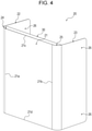
Fig. 1] Fig. 1 is a perspective view of an electric apparatus device according to an embodiment of the present disclosure. - [
Fig. 2] Fig. 2 is a perspective view of the electric apparatus device shown inFig. 1 with a cover body removed from a case body. - [
Fig. 3] Fig. 3 is a perspective view of the case body shown inFig. 2 . - [
Fig. 4] Fig. 4 is a perspective view of the cover body shown inFig. 2 . - [
Fig. 5] Fig. 5 is a perspective view showing a waterproof frame mounted on the cover body. - [
Fig. 6] Fig. 6 is a cross-sectional view of the cover body shown inFig. 4 . - [
Fig. 7] Fig. 7 is a cross-sectional view of the electric apparatus device shown inFig. 1 . - [
Fig. 8] Fig. 8 is a longitudinal sectional view of the electric apparatus device shown inFig. 1 . - [
Fig. 9] Fig. 9 is an explanatory view schematically showing a structure of a seal member. - [
Fig. 10A] Fig. 10A schematically shows a cross section of an electric apparatus device of a comparative example. - [
Fig. 10B] Fig. 10B schematically shows a cross section of the electric apparatus device of the present embodiment. - Hitherto, a case for an electric apparatus device has been required not only to have functionality, such as being waterproof as mentioned above, but also to have higher designability (design properties).
- An object of the present disclosure is to provide a case for an electric apparatus and an electric apparatus device, each of whose designability is increased while its functionality is ensured.
- According to an embodiment of the present disclosure, it is possible to provide a case for an electric apparatus and an electric apparatus device, each of whose designability is increased while its functionality is ensured.
- An embodiment of the present disclosure is exemplified in detail below with reference to the drawings.
- As shown in
Fig. 1 , anelectric apparatus device 1 according to the embodiment includes acase 2 for an electric apparatus and anelectric apparatus 3 in thecase 2 for an electric apparatus. - In the present embodiment, the
electric apparatus device 1 is constituted as a home storage battery device. Theelectric apparatus 3 schematically shown inFig. 1 is a storage battery. The storage battery includes, for example, a storage battery body and a control circuit that controls the operation of the storage battery body. As the storage battery body mentioned above, for example, a lithium-ion battery or a nickel-metal hydride battery can be used. Theelectric apparatus device 1 constituted by the storage battery device can be used for, for example, storing electric power produced by, for example, a solar battery by connecting theelectric apparatus device 1 to the solar battery, the solar battery being installed on the roof of a house or the like. - The
electric apparatus device 1 can be constituted so that thecase 2 for an electric apparatus accommodates, in addition to theelectric apparatus 3, a plurality of types of electric apparatuses having different functions or structures, such as a power conversion device, a fuel cell, or a ventilation fan. Theelectric apparatus device 1 can be constituted so that thecase 2 for an electric apparatus accommodates, in addition to theelectric apparatus 3, for example, a material, such as a heat-insulating material or a cushioning material. - Note that the
electric apparatus 3 that is in thecase 2 for an electric apparatus is not limited to the storage battery described above and may be, for example, other electric apparatuses having different functions or structures, such as a fuel battery, a power conversion device, a transformation device, or a device having the function of supplying electric power to a commercial power system. - The
electric apparatus device 1 can be installed outdoors. In the present embodiment, theelectric apparatus device 1 is installed at, for example, an outer wall of houses with a mounting fitting, a stand, or the like. - Note that the place where the
electric apparatus device 1 is installed is not limited to inside a building. Theelectric apparatus device 1 may be installed at other places, such as outside a building. - As shown in
Fig. 2 , thecase 2 for an electric apparatus that accommodates theelectric apparatus 3 includes acase body 10, acover body 20, awaterproof frame 30, and aseal member 40. - As shown in
Fig. 3 , thecase body 10 has a box shape including afirst wall 11, asecond wall 12, athird wall 13, afourth wall 14, and afifth wall 15. In the present embodiment, thecase body 10 is formed by, for example, processing one metal plate, such as a steel plate, an aluminum-alloy plate, or a stainless-steel plate. Such a structure makes it possible to manufacture at a low cost thecase body 10 having the shape above. - The
case body 10 is not limited to one formed from the metal plate mentioned above, and may be one manufactured by using other materials or manufacturing methods, for example, a metal casting, such as an aluminum alloy casting or a part made by injection molding of a synthetic resin material. Thecase body 10 may be constituted by integrally connecting thefirst wall 11, thesecond wall 12, thethird wall 13, thefourth wall 14, and thefifth wall 15, which are formed as separated walls, by, for example, welding, bonding, or fastening them. - The
first wall 11 has afirst side 11a and asecond side 11b that are parallel to each other, and athird side 11c and afourth side 11d that are orthogonal to thefirst side 11a and thesecond side 11b and that are parallel to each other. Thefirst wall 11 has acut portion 11e having a rectangular shape recessed toward thefirst side 11a along thefourth side 11d from thesecond side 11b. Thus, thefirst wall 11 has an outer shape that is a substantially rectangular plate shape, with the outer shape having the foursides 11a to 11d and having thecut portion 11e in a portion thereof. In the present embodiment, thefirst wall 11 constitutes a rear surface of thecase body 10. - The
second wall 12 has a rectangular plate shape that is more elongated than the shape of thefirst wall 11, and is continuous with thefirst side 11a of thefirst wall 11 at right angles to thefirst side 11a. - The
third wall 13 has an elongated rectangular plate shape that is similar to the shape of thesecond wall 12, and is continuous with thesecond side 11b of thefirst wall 11 at right angles to thesecond side 11b and faces thesecond wall 12. Thethird wall 13 has arectangular cut portion 13a that is recessed from thesecond side 11b in a direction away from thefirst wall 11. - In the present embodiment, the
second wall 12 and thethird wall 13 constitute side surfaces that face each other in a parallel state and that each face sideways with respect to thecase body 10. - The
fourth wall 14 has a plate shape that is more elongated than the shape of thefirst wall 11, and is continuous with thethird side 11c of thefirst wall 11 at right angles to thethird side 11c and with upper sides, which are upper sides inFig. 3 , of the respectivesecond wall 12 andthird wall 13 at right angles to the upper sides. In the present embodiment, thefourth wall 14 constitutes a top surface of thecase body 10 that faces upward. - A protruding
wall 16 that protrudes with respect to thesecond wall 12 and thethird wall 13 in a direction away from thefirst wall 11 is integrally disposed with thefourth wall 14. The protrudingwall 16 has anend surface 16a that is parallel to a surface of thefirst wall 11 and whose both side end surfaces are curved with a predetermined curvature. - The
fifth wall 15 has an elongated plate shape that is similar to the shape of thefourth wall 14. Thefifth wall 15 is continuous with thefourth side 11d of thefirst wall 11 at right angles to thefourth side 11d and with lower sides, which are lower sides inFig. 3 , of the respectivesecond wall 12 andthird wall 13 at right angles to the lower sides; and faces thefourth wall 14. In the present embodiment, thefifth wall 15 constitutes a bottom surface of thecase body 10 that faces downward. - Note that the
cut portion 11e and thecut portion 13a of thecase body 10 are closed from an inner side of thecase body 10 by acover wall 17. - The inside of the
case body 10 is anaccommodation space 10a that accommodates theelectric apparatus 3. A side of thecase body 10 opposite to thefirst wall 11 is anopening 10b. By removing thecover body 20 from thecase body 10 and causing theopening 10b to communicate with the outside, it is possible to dispose theelectric apparatus 3 in theaccommodation space 10a through theopening 10b. - The
case body 10 has a ring-shapedcase seal surface 18 that is constituted in the same plane parallel to thefirst wall 11, and that surrounds theopening 10b. - More specifically, the
case seal surface 18 has a firstcase seal surface 18a, a secondcase seal surface 18b, a thirdcase seal surface 18c, and a fourthcase seal surface 18d. The firstcase seal surface 18a is constituted as an outwardly facing surface of a flange-like portion formed by inwardly bending at right angles a side portion of thesecond wall 12 on a side of theopening 10b, the outwardly facing surface being parallel to thefirst wall 11. The secondcase seal surface 18b is constituted as an outwardly facing surface of a flange-like portion formed by inwardly bending at right angles a side portion of thethird wall 13 on a side of theopening 10b, the outwardly facing surface being parallel to thefirst wall 11. The thirdcase seal surface 18c is constituted as an outwardly facing surface of aframe material 19 fixed to a lower surface of the protrudingwall 16 facing thefifth wall 15, the outwardly facing surface being parallel to thefirst wall 11. The fourthcase seal surface 18d is constituted as an outwardly facing surface of a flange-like portion formed by outwardly bending at right angles a side portion of thefifth wall 15 on a side of theopening 10b, the outwardly facing surface being parallel to thefirst wall 11. One end of the thirdcase seal surface 18c is continuous with one end of the firstcase seal surface 18a, one end of the secondcase seal surface 18b is continuous with the other end of the thirdcase seal surface 18c, one end of the fourthcase seal surface 18d is continuous with the other end of the secondcase seal surface 18b, and the other end of the firstcase seal surface 18a is continuous with the other end of the fourthcase seal surface 18d. In this way, thecase body 10 has the ring-shapedcase seal surface 18 surrounding theopening 10b as a result of the firstcase seal surface 18a, the secondcase seal surface 18b, the thirdcase seal surface 18c, and the fourthcase seal surface 18d being continuous with each other in the form of a ring. - As shown in
Fig. 4 , thecover body 20, which is an external panel, has a U shape (C shape) in cross section including aflat cover portion 21, a firstside cover portion 22 that covers thesecond wall 12 from an outer side thereof, a secondside cover portion 23 that covers thethird wall 13 from an outer side thereof, a firstcurved cover portion 24 that is continuous with theflat cover portion 21 and the firstside cover portion 22, and a secondcurved cover portion 25 that is continuous with theflat cover portion 21 and the secondside cover portion 23. The plate thickness of thecover body 20 can be set to any value, and may be, for example, 0.3 mm to 3.5 mm. - The
cover body 20 can be formed by, for example, bending one metal plate, such as a steel plate, an aluminum-alloy plate, or a stainless-steel plate. Such a structure makes it possible to easily manufacture at a low cost thecover body 20 having the shape above by simple bending. - The
cover body 20 is not limited to one in which theflat cover portion 21, the firstside cover portion 22, the secondside cover portion 23, the firstcurved cover portion 24, and the secondcurved cover portion 25 are integrally formed with each other by bending one metal plate. Thecover body 20 can be constituted by integrally connecting theflat cover portion 21, the firstside cover portion 22, the secondside cover portion 23, the firstcurved cover portion 24, and the secondcurved cover portion 25, which are formed as separate members, by, for example, welding, bonding, or fastening them. Thecover body 20 is not limited to one formed of a metal, and may be one formed of other materials, such as a part made by injection molding of a synthetic resin material. - The
flat cover portion 21 has afirst side 21a and asecond side 21b that are parallel to thefirst side 11a of thefirst wall 11 of thecase body 10. Theflat cover portion 21 has athird side 21c and afourth side 21d that are parallel to thethird side 11c of thefirst wall 11. In this way, theflat cover portion 21 has an outer shape that is a rectangular plate shape, the outer shape having the foursides 21a to 21d. - The first
curved cover portion 24 is integrated and continuous with thefirst side 21a of theflat cover portion 21. The firstcurved cover portion 24 is bent toward thefirst wall 11 from thefirst side 21a to have an arc shape having a central angle of 90 degrees with an axis parallel to thefirst side 21a being a central axis. - The second
curved cover portion 25 is integrated and continuous with thesecond side 21b of theflat cover portion 21. The secondcurved cover portion 25 is bent toward thefirst wall 11 from thesecond side 21b to have an arc shape having a central angle of 90 degrees with an axis parallel to thesecond side 21b being a central axis. - The radius of the first
curved cover portion 24 that is curved in an arc shape and the radius of the secondcurved cover portion 25 that is curved in an arc shape are substantially equal to the curvatures of the two curved side end surfaces of the protrudingwall 16. - The first
side cover portion 22 has a rectangular plate shape that is parallel to thesecond wall 12, and is integrated and continuous with the firstcurved cover portion 24. - The second
side cover portion 23 has a rectangular plate shape that is parallel to thethird wall 13, and is integrated and continuous with the secondcurved cover portion 25. - The first
side cover portion 22 and the secondside cover portion 23 each have two mount holes 26 (with regard to the firstside cover portion 22, only one of the mount holes 26 is shown). On the other hand, as shown inFig. 3 , two threadedholes 50 are disposed at a first-wall-11 side of thesecond wall 12 of thecase body 10 and two threadedholes 50 are disposed at a first-wall-11 side of thethird wall 13 of thecase body 10, with one of the two threadedholes 50 being disposed toward thefourth wall 14 and the other of the two threadedholes 50 being disposed toward thefifth wall 15. - As shown in
Fig. 1 , thecover body 20 is mounted on thecase body 10 by screwing threadedmembers 51 inserted into the mount holes 26 of thecover body 20 into the corresponding threadedholes 50 of thecase body 10. Thecover body 20 mounted on thecase body 10 covers theopening 10b of thecase body 10. Note that, as the threadedmembers 51, rod-tip screws having at their tips rod-like portions whose diameter is smaller than the diameter of the roots of screw threads can be used. - As shown in
Figs. 5 and6 , thewaterproof frame 30 is disposed at thecover body 20 and on an inner side of theflat cover portion 21 and the pair of curved cover portions (the firstcurved cover portion 24 and the second curved cover portion 25). - More specifically, the
waterproof frame 30 has a box shape including a fixingwall portion 31, a firstpartition wall portion 32, a secondpartition wall portion 33, a thirdpartition wall portion 34, and a fourthpartition wall portion 35, with a portion of thewaterproof frame 30 facing the fixingwall portion 31 being anopening 30a. The fixingwall portion 31 has a rectangular plate shape having a size that is the same as or smaller than the size of theflat cover portion 21. The firstpartition wall portion 32 is continuous with a side portion of the fixingwall portion 31 on a side of the firstcurved cover portion 24. The secondpartition wall portion 33 is continuous with a side portion of the fixingwall portion 31 on a side of the secondcurved cover portion 25. The thirdpartition wall portion 34 is continuous with a side portion of the fixingwall portion 31 on a side of thethird side 21c and with the firstpartition wall portion 32 and the secondpartition wall portion 33. The fourthpartition wall portion 35 is continuous with a side portion of the fixingwall portion 31 on a side of thefourth side 21d and with the firstpartition wall portion 32 and the secondpartition wall portion 33. In a state in which thecover body 20 is mounted on thecase body 10, theopening 30a of thewaterproof frame 30 is continuous with theopening 10b of thecase body 10, and an internal space of thewaterproof frame 30 communicates with theaccommodation space 10a of thecase body 10, and, together with theaccommodation space 10a, constitutes an internal space of thecase 2 for an electric apparatus. - The
waterproof frame 30 is integrated with thecover body 20 by fixing the fixingwall portion 31 to theflat cover portion 21 by, for example, a method such as spot welding or bonding. Portions of thewaterproof frame 30 other than theopening 30a are hermetically sealed air-tightly or fluid-tightly. - Note that the
waterproof frame 30 can be constituted without including the fixingwall portion 31 by directly fixing the firstpartition wall portion 32, the secondpartition wall portion 33, the thirdpartition wall portion 34, and the fourthpartition wall portion 35 to theflat cover portion 21 by a method such as welding. In this case, an open end on a side opposite to anopening 30a of a ring-shaped frame body portion that is constituted by the firstpartition wall portion 32, the secondpartition wall portion 33, the thirdpartition wall portion 34, and the fourth partition wall portion is hermetically sealed air-tightly or fluid-tightly by theflat cover portion 21. - Each portion of the
waterproof frame 30 is more specifically described. The firstpartition wall portion 32 has an elongated flat plate shape extending parallel to thefirst side 21a of theflat cover portion 21, and extends in a tilted manner toward the firstcurved cover portion 24 in a direction perpendicular to theflat cover portion 21 from theflat cover portion 21 toward the case seal surface 18 (in a direction away from the flat cover portion 21). A side portion of the firstpartition wall portion 32 opposite to a side portion thereof that is disposed consecutively with theflat cover portion 21 abuts upon the firstside cover portion 22, and afirst support wall 36 that is integrated and continuous with the side portion is fixed to the firstside cover portion 22 by a method, such as spot welding or bonding. Afirst communication portion 60 that is constituted as a space that extends in a direction along thefirst side 21a of theflat cover portion 21 and opens toward the thirdpartition wall portion 34 and the fourthpartition wall portion 35 is disposed between the firstpartition wall portion 32 and the firstcurved cover portion 24. - Similarly, the second
partition wall portion 33 has an elongated flat plate shape extending parallel to thesecond side 21b of theflat cover portion 21, and extends in a tilted manner toward the secondcurved cover portion 25 in a direction perpendicular to theflat cover portion 21 from theflat cover portion 21 toward the case seal surface 18 (in a direction away from the flat cover portion 21). A side portion of the secondpartition wall portion 33 opposite to a side portion thereof that is disposed consecutively with theflat cover portion 21 abuts upon the secondside cover portion 23, and asecond support wall 37 that is integrated and continuous with the side portion is fixed to the secondside cover portion 23 by a method, such as spot welding or bonding. Asecond communication portion 61 that is constituted as a space that extends in a direction along thesecond side 21b of theflat cover portion 21 and opens toward the thirdpartition wall portion 34 and the fourthpartition wall portion 35 is disposed between the secondpartition wall portion 33 and the secondcurved cover portion 25. - The third
partition wall portion 34 has an elongated flat trapezoidal shape extending parallel to thethird side 21c of theflat cover portion 21, and extends in a tilted manner in a direction away from the fourthpartition wall portion 35 toward the case seal surface 18 from the flat cover portion 21 (in a direction away from the flat cover portion 21). Two side portions of the thirdpartition wall portion 34 are continuous with a corresponding one of the firstpartition wall portion 32 and the secondpartition wall portion 33. - The fourth
partition wall portion 35 has an elongated flat trapezoidal shape extending parallel to thefourth side 21d of theflat cover portion 21, and extends perpendicularly to the fixingwall portion 31 toward the case seal surface 18 from the flat cover portion 21 (in a direction away from the flat cover portion 21). Two side portions of the fourthpartition wall portion 35 are continuous with a corresponding one of the firstpartition wall portion 32 and the secondpartition wall portion 33. - The
waterproof frame 30 has a ring-shapedcover seal surface 38 that is constituted in the same plane parallel to theflat cover portion 21 and that surrounds theopening 30a. As shown inFigs. 7 and8 , in the state in which thecover body 20 is mounted on thecase body 10, thecover seal surface 38 faces thecase seal surface 18. Here, thecover seal surface 38 and thecase seal surface 18 are parallel to each other. - More specifically, the
cover seal surface 38 has a firstcover seal surface 38a, a secondcover seal surface 38b, a thirdcover seal surface 38c, and a fourthcover seal surface 38d. The firstcover seal surface 38a is constituted as an outwardly facing surface of a flange-like portion formed by inwardly bending a side portion of thefirst support wall 36, the outwardly facing surface being parallel to theflat cover portion 21. The secondcover seal surface 38b is constituted as an outwardly facing surface of a flange-like portion formed by inwardly bending a side portion of thesecond support wall 37, the outwardly facing surface being parallel to theflat cover portion 21. The thirdcover seal surface 38c is constituted as an outwardly facing surface of a flange-like portion formed by inwardly bending a side portion of the thirdpartition wall portion 34 on a side of theopening 30a, the outwardly facing surface being parallel to theflat cover portion 21. The fourthcover seal surface 38d is constituted as an outwardly facing surface of a flange-like portion formed by inwardly bending a side portion of the fourthpartition wall portion 35 on the side of theopening 30a, the outwardly facing surface being parallel to theflat cover portion 21. One end of the thirdcover seal surface 38c is continuous with one end of the firstcover seal surface 38a, one end of the secondcover seal surface 38b is continuous with the other end of the thirdcover seal surface 38c, one end of the fourthcover seal surface 38d is continuous with the other end of the secondcover seal surface 38b, and the other end of the firstcover seal surface 38a is continuous with the other end of the fourthcover seal surface 38d. In this way, thewaterproof frame 30 has the ring-shapedcover seal surface 38 that surrounds theopening 30a as a result of the firstcover seal surface 38a, the secondcover seal surface 38b, the thirdcover seal surface 38c, and the fourthcover seal surface 38d being continuous with each other in the form of a ring, and that faces thecase seal surface 18. - In the present embodiment, the
cover seal surface 38 is disposed further away than the pair of curved cover portions (the firstcurved cover portion 24 and the second curved cover portion 25) from theflat cover portion 21. That is, thecover seal surface 38 is, in a direction perpendicular to theflat cover portion 21, disposed further away than a side portion of the firstcurved cover portion 24 that is continuous with the firstside cover portion 22 and a side portion of the secondcurved cover portion 25 that is continuous with the secondside cover portion 23 from theflat cover portion 21. Therefore, the firstcover seal surface 38a is disposed adjacent to the firstside cover portion 22, and the secondcover seal surface 38b is disposed adjacent to the secondside cover portion 23. - The
waterproof frame 30 having the structure above can be formed by, for example, processing one metal plate, such as a steel plate, an aluminum-alloy plate, or a stainless-steel plate. Such a structure makes it possible to manufacture at a low cost thewaterproof frame 30 having the shape above. - As shown in
Fig. 9 , theseal member 40 is constituted in the form of a ring that is in correspondence with the shape of thecase seal surface 18 and the shape of thecover seal surface 38. As shown inFigs. 7 and8 , in the state in which thecover body 20 is mounted on thecase body 10, theseal member 40 being elastically deformed by a predetermined proportion in a compression direction is disposed between thecase seal surface 18 and thecover seal surface 38. Theseal member 40 is in contact with the ring-shapedcase seal surface 18 and the ring-shapedcover seal surface 38 over the entire peripheries thereof, and seals a location between thecase seal surface 18 and thecover seal surface 38 by a degree that does not allow entry of water, such as rainwater. That is, theseal member 40 is constituted to have a waterproof function that seals a location between thecase seal surface 18 and thecover seal surface 38 by being disposed between thecase seal surface 18 and thecover seal surface 38. - In this way, by disposing the
seal member 40 between thecase seal surface 18 of thecase body 10 and thecover seal surface 38 of thewaterproof frame 30, disposed at thecover body 20, it is possible to prevent water, such as rainwater, from entering theaccommodation space 10a in thecase body 10 from a location between thecase body 10 and thecover body 20 or thewaterproof frame 30. - The
seal member 40 can be made of, for example, an elastic material, such synthetic rubber or elastomer. Theseal member 40 may be formed of rubber sponge, which is an ethylenepropylene rubber foam material. Note that theseal member 40 can have a structure or can be made of a material other than those described above. - As shown in
Fig. 9 , in the present embodiment, theseal member 40 is constituted to have the shape of one ring by combining four members, that is, afirst seal portion 41, asecond seal portion 42, athird seal portion 43, and afourth seal portion 44. - The
first seal portion 41 is primarily disposed between the firstcase seal surface 18a and the firstcover seal surface 38a opposite thereto, and includes abody portion 41a that extends along the firstcase seal surface 18a and the firstcover seal surface 38a and anauxiliary body portion 41c that is disposed consecutively with one end of thebody portion 41a through a steppedportion 41b. Theauxiliary body portion 41c is displaced toward an inner side of thecase body 10 by an amount corresponding to the width of thebody portion 41a from thebody portion 41a. On the other end of thebody portion 41a, thefirst seal portion 41 has a protrudingportion 41d that protrudes inward from a side portion of thebody portion 41a. The protrudingportion 41d is displaced by an amount corresponding to the width of thefourth seal portion 44 from the other end of thebody portion 41a. - The
second seal portion 42 has a shape that is symmetrical to thefirst seal portion 41. Thesecond seal portion 42 is primarily disposed between the secondcase seal surface 18b and the secondcover seal surface 38b opposite thereto, and includes abody portion 42a that extends along the secondcase seal surface 18b and the secondcover seal surface 38b and anauxiliary body portion 42c that is disposed consecutively with one end of thebody portion 42a through a steppedportion 42b. Theauxiliary body portion 42c is displaced toward an inner side of thecase body 10 by an amount corresponding to the width of thebody portion 42a from thebody portion 42a. On the other end of thebody portion 42a, thesecond seal portion 42 has a protrudingportion 42d that protrudes inward from a side portion of thebody portion 42a. The protrudingportion 42d is displaced by an amount corresponding to the width of thefourth seal portion 44 from the other end of thebody portion 42a. - The
third seal portion 43 includes abody portion 43a, a firstauxiliary body portion 43b, and a secondauxiliary body portion 43c. Thebody portion 43a is disposed between the thirdcase seal surface 18c and the thirdcover seal surface 38c opposite thereto. The firstauxiliary body portion 43b is continuous with one end of thebody portion 43a, extends in a direction perpendicular to thebody portion 43a, and is disposed between the firstcase seal surface 18a and the firstcover seal surface 38a. The secondauxiliary body portion 43c is continuous with the other end of thebody portion 43a, extends in a direction perpendicular to thebody portion 43a, and is disposed between the secondcase seal surface 18b and the secondcover seal surface 38b. - A tip of the first
auxiliary body portion 43b that faces in a direction opposite to thebody portion 43a abuts upon the one end of thebody portion 41a of thefirst seal portion 41 at which the steppedportion 41b is disposed, and a side portion of the firstauxiliary body portion 43b abuts upon a side portion of theauxiliary body portion 41c of thefirst seal portion 41. Aboundary 45a between the tip of the firstauxiliary body portion 43b of thethird seal portion 43 and the one end of thebody portion 41a of thefirst seal portion 41 extends in a direction parallel to thefourth wall 14 that constitutes the top wall of thecase body 10, and aboundary 45b between the side portion of the firstauxiliary body portion 43b and the side portion of theauxiliary body portion 41c of thefirst seal portion 41 extends toward thefourth wall 14 from theboundary 45a and perpendicularly to theboundary 45a. - Similarly, a tip of the second
auxiliary body portion 43c that faces in a direction opposite to thebody portion 43a abuts upon one end of thebody portion 42a of thesecond seal portion 42 at which the steppedportion 42b is disposed, and a side portion of the secondauxiliary body portion 43c abuts upon a side portion of theauxiliary body portion 42c of thesecond seal portion 42. Aboundary 46a between the tip of the firstauxiliary body portion 43c of thethird seal portion 43 and the one end of thebody portion 42a of thesecond seal portion 42 extends in a direction parallel to thefourth wall 14 that constitutes the top wall of thecase body 10, and aboundary 46b between the side portion of the secondauxiliary body portion 43c and the side portion of theauxiliary body portion 42c of thesecond seal portion 42 extends toward thefourth wall 14 from theboundary 46a and perpendicularly to theboundary 46a. - The
fourth seal portion 44 is disposed between the fourthcase seal surface 18d and the fourthcover seal surface 38d opposite thereto. One end of thefourth seal portion 44 abuts upon thebody portion 41a of thefirst seal portion 41 from a side of thebody portion 41a, and a side portion of thefourth seal portion 44 on a side of the one end abuts upon the protrudingportion 41d of thefirst seal portion 41. Aboundary 47a between a tip of thefourth seal portion 44 and thebody portion 41a of thefirst seal portion 41 extends toward thefourth wall 14 that constitutes the top wall of thecase body 10, and aboundary 47b between thefourth seal portion 44 and the protrudingportion 41d of thefirst seal portion 41 extends perpendicularly to theboundary 47a. Similarly, aboundary 48a between the other end of thefourth seal portion 44 and thebody portion 42a of thesecond seal portion 42 extends toward thefourth wall 14 that constitutes the top wall of thecase body 10, and aboundary 48b between thefourth seal portion 44 and the protrudingportion 42d of thesecond seal portion 42 extends perpendicularly to theboundary 48a. - In this way, by constituting the
seal member 40 to have one ring shape by combining four members, that is, thefirst seal portion 41, thesecond seal portion 42, thethird seal portion 43, and thefourth seal portion 44, when theseal member 40 is to be manufactured by being punched out from a rectangular sheet material, thefirst seal portion 41, thesecond seal portion 42, thethird seal portion 43, and thefourth seal portion 44 can be punched out from one sheet material with a good yield than when a ring-shaped seal member is to be punched out from one sheet material. Therefore, a plurality ofseal members 40 can be manufactured from one sheet material, and thus manufacturing costs of theseal member 40 can be reduced. - In the
case 2 for an electric apparatus in a state sealed by theseal member 40, the pressure of air in theaccommodation space 10a changes due to, for example, heat produced by theelectric apparatus 3 or a change in the temperature of the environment in which theelectric apparatus device 1 is installed. Therefore, when the ring-shapedseal member 40 has a structure in which theseal member 40 is divided into a plurality of portions and the portions are joined to each other, air enters and leaves the boundaries of the corresponding joined portions as the pressure of the air in theaccommodation space 10a changes. Here, when water adheres to outer surfaces of the joined portions of theseal member 40, this water, together with the air, may be sucked into theaccommodation space 10a of thecase body 10 through the boundaries of the corresponding joined portions, and the waterproofness of theelectric apparatus device 1 or thecase 2 for an electric apparatus may be reduced. - With regard to such a problem, in the present embodiment, while the
seal member 40 is constituted to have one ring shape by combining four members, that is, thefirst seal portion 41, thesecond seal portion 42, thethird seal portion 43, and thefourth seal portion 44, these joined portions are constituted to have a corresponding one of theboundaries fourth wall 14, or to have a corresponding one of theboundaries respective boundaries seal member 40 is sucked into theaccommodation space 10a of thecase body 10 through the boundaries of the joined portions, it is possible to suppress the water from being sucked into theaccommodation space 10a of thecase body 10 by causing the water to drop due to its own weight at theboundaries fourth wall 14. Consequently, it is possible to increase the waterproofness of theelectric apparatus device 1 or thecase 2 for an electric apparatus. - Note that the
seal member 40 can have, instead of a divided structure, a structure that is formed to have a ring shape by a member having an integrated structure. - In the
electric apparatus device 1 or thecase 2 for an electric apparatus of the present embodiment having the structures above, thecover body 20 includes the firstcurved cover portion 24 and the secondcurved cover portion 25. Therefore, with thecover body 20 having a good external appearance in which the corner portions are rounded, compared with when the firstcurved cover portion 24 and the secondcurved cover portion 25 are not disposed at thecover body 20, thecase 2 for an electric apparatus and theelectric apparatus device 1 of the present embodiment that include thecover body 20 having the shape above can have higher designability (design properties). - In the
electric apparatus device 1 or thecase 2 for an electric apparatus of the present embodiment, the firstcurved cover portion 24 and the secondcurved cover portion 25 that are curved in an arc shape may have a radius that is, for example, greater than or equal to 10 mm. Due to such a structure, the shape formed by rounding the corner portions by disposing the firstcurved cover portion 24 and the secondcurved cover portion 25 can sufficiently attract the notice of a person who looks at the shape. Therefore, thecover body 20, and theelectric apparatus device 1 or thecase 2 for an electric apparatus that use thecover body 20 can have higher designability (design properties). - The first
curved cover portion 24 and the secondcurved cover portion 25 that are curved in an arc shape may have a radius in the range of, for example, 20 to 80 mm. Due to such a structure, the shape formed by rounding the corner portions by disposing the firstcurved cover portion 24 and the secondcurved cover portion 25 can moderately attract the notice of a person who looks at the shape. Therefore, thecover body 20 and theelectric apparatus device 1 or thecase 2 for an electric apparatus that use thecover body 20 can higher designability (design properties). - In the present embodiment, the
cover body 20 has a U shape in cross section including theflat cover portion 21, the firstside cover portion 22, the secondside cover portion 23, the firstcurved cover portion 24, and the secondcurved cover portion 25. Therefore, thecover body 20 can have a better external appearance in which both corner portions with theflat cover portion 21 inbetween are rounded. Consequently, compared with when curved cover portions are not disposed at the cover body, thecover body 20 having the shape above and theelectric apparatus device 1 or thecase 2 for an electric apparatus that use thecover body 20 can have higher designability (design properties). - In the present embodiment, since the
second wall 12 and thethird wall 13 of thecase body 10 are covered by the firstside cover portion 22 and the secondside cover portion 23, respectively, it is possible to prevent a person from directly touching with his/her hand thesecond wall 12 and thethird wall 13 of thecase body 10 heated by heat produced by theelectric apparatus 3. -
Fig. 10A schematically shows a cross section of an electric apparatus device of a comparative example.Fig. 10B schematically shows a cross section of the electric apparatus device of the present embodiment. - As described above, by constituting the
cover body 20 to include the firstcurved cover portion 24 and the secondcurved cover portion 25, theelectric apparatus device 1 or thecase 2 for an electric apparatus can have higher designability (design properties). - However, when, as in the electric apparatus device of the comparative example shown in
Fig. 10A , acover body 120 includes a firstcurved cover portion 124 and a secondcurved cover portion 125 but is not provided with a waterproof frame, a waterproof line L between acase seal surface 118 and acover seal surface 138 provided by aseal member 140 needs to be provided at a portion of aflat cover portion 121 on an inner side of the firstcurved cover portion 124 and the secondcurved cover portion 125. Therefore, thecover body 120 becomes larger than thecase body 10 in a width direction by an amount corresponding to the radius of the firstcurved cover portion 124 and the secondcurved cover portion 125. In particular, when thecover body 120 includes a firstside cover portion 122 and a secondside cover portion 123, a problem that the electric apparatus device becomes large due to the firstside cover portion 122 being disposed away from asecond wall 112 and the secondside cover portion 123 being disposed away from athird wall 113 and wasted space being formed between the firstside cover portion 122 and thesecond wall 112 and wasted space being formed between the secondside cover portion 123 and thethird wall 113. - In contrast, as shown in
Fig. 10B , in theelectric apparatus device 1 of the present embodiment, the firstcurved cover portion 24 and the secondcurved cover portion 25 are formed in a recessed state at thecover body 20 including the firstcurved cover portion 24 and the secondcurved cover portion 25, thewaterproof frame 30 that is disposed on an inner side of theflat cover portion 21 and the pair ofcurved cover portions cover seal surface 38 is disposed at thewaterproof frame 30. Therefore, a waterproof line between thecase seal surface 18 and thecover seal surface 38 provided by theseal member 40 can be provided not only at a portion of theflat cover portion 21, but also in a range extending toward the firstcurved cover portion 24 and the secondcurved cover portion 25 from theflat cover portion 21. - Therefore, even if the
cover body 20 includes the firstcurved cover portion 24 and the secondcurved cover portion 25, it is possible to ensure a waterproof structure while suppressing thecover body 20 from increasing in size and theelectric apparatus device 1 or thecase 2 for an electric apparatus from increasing in size. - In particular, in the present embodiment, since the
cover seal surface 38 is disposed further away than the firstcurved cover portion 24 and the secondcurved cover portion 25 from theflat cover portion 21, the waterproof line L between thecase seal surface 18 and thecover seal surface 38 provided by theseal member 40 can be provided not only at a portion of theflat cover portion 21, but also in an entire range in a width direction on an inner side of thecover body 20 including the firstcurved cover portion 24 and the secondcurved cover portion 25. Therefore, even if thecover body 20 includes the firstcurved cover portion 24 and the secondcurved cover portion 25, thecover body 20 is formed with a size in correspondence with the size of thecase body 10, and a waterproof structure can be ensured while minimizing the size of theelectric apparatus device 1 or thecase 2 for an electric apparatus. - Even if the
cover body 20 includes the firstside cover portion 22 and the secondside cover portion 23, it is possible to ensure a waterproof structure while eliminating a gap between the firstside cover portion 22 and thesecond wall 12 and a gap between the secondside cover portion 23 and thethird wall 13 and minimizing the size of theelectric apparatus device 1 or thecase 2 for an electric apparatus. - In this case, it is possible to provide a structure in which a boss is disposed on an outer surface of the
second wall 12 and on an outer surface of thethird wall 13 by a predetermined projection amount and thus the gap between the firstside cover portion 22 and thesecond wall 12 and the gap between the secondside cover portion 23 and thethird wall 13 are adjusted to be uniform. The bosses can be disposed, for example, around the threadedholes 50 in the outer surface of thesecond wall 12 and the threadedholes 50 in the outer surface of thethird wall 13. - Note that since the internal space of the
waterproof frame 30 that is disposed at thecover body 20 communicates with theaccommodation space 10a of thecase body 10 and, together with theaccommodation space 10a, constitutes the internal space of thecase 2 for an electric apparatus, it is possible to reduce the size of thecase body 10 by an amount corresponding to the size of thewaterproof frame 30. Therefore, even if thewaterproof frame 30 is disposed at thecover body 20, it is possible to suppress the size of theelectric apparatus device 1 or thecase 2 for an electric apparatus from increasing. - As shown in
Figs. 3 and8 , thecase body 10 can include agutter member 70. - The
gutter member 70 is formed as a rail-like member having a substantially U shape (C shape) in cross section in which an open portion faces the protrudingwall 16, and is integrated and continuous with an edge of the thirdcase seal surface 18c facing theopening 10b. Thegutter member 70 extends in a direction parallel to thefourth wall 14 in the entire range between thesecond wall 12 and thethird wall 13, protrudes toward an outer side of thecase body 10 from theopening 10b, and is disposed below the thirdcase seal surface 18c of thecase seal surface 18 extending along thethird side 21c of theflat cover portion 21. - The
gutter member 70 having the structure above can receive a liquid, such as water, and can discharge the received liquid to the outside from two end portions thereof. - Note that the
gutter member 70 can be constituted as a member formed separately from the thirdcase seal surface 18c and fixed to thecase body 10. - When the
electric apparatus device 1 is installed outdoors in an orientation in which thefourth wall 14 faces upward to be the top wall, water, such as rainwater, may accumulate on thebody portion 43a of thethird seal portion 43 of theseal member 40 disposed between the thirdcase seal surface 18c of thecase seal surface 18 and the thirdcover seal surface 38c of thecover seal surface 38. - In this case, the water flows toward the
flat cover portion 21 along the thirdpartition wall portion 34 that is tilted to be lower toward theflat cover portion 21, flows from there toward a lower end of thecover body 20 through thefirst communication portion 60 and thesecond communication portion 61 that are disposed as drainage channels on respective side portions of the thirdpartition wall portion 34, and is discharged to the outside from a gap between the firstcurved cover portion 24 and a curved surface of the protrudingwall 16 and a gap between the secondcurved cover portion 25 and a curved surface of the protrudingwall 16. - However, the water that has accumulated on the
body portion 43a of thethird seal portion 43 disposed between the thirdcase seal surface 18c and the thirdcover seal surface 38c may remain on thebody portion 43a of thethird seal portion 43 without being discharged. In this case, when for, for example, maintenance of theelectric apparatus 3, thecover body 20 is removed from thecase body 10 while the water remains on thebody portion 43a of thethird seal portion 43, the water may enter theaccommodation space 10a of thecase body 10 and adhere to theelectric apparatus 3. - In contrast, in the
electric apparatus device 1 of the present embodiment, since thecase body 10 is provided with thegutter member 70 that is disposed below the thirdcase seal surface 18c, even if thecover body 20 is removed from thecase body 10 while water accumulated on thebody portion 43a of thethird seal portion 43 remains on thebody portion 43a of thethird seal portion 43 without being discharged, the water can be received by thegutter member 70 and discharged to the outside of thecase body 10 from the two ends of thegutter member 70. Therefore, it is possible to prevent the water from unexpectedly entering theaccommodation space 10a of thecase body 10 and adhering to theelectric apparatus 3. - The present disclosure is not limited to the embodiment above, and can be variously changed within a scope that does not depart from the spirit thereof.
- For example, in the present embodiment, although the
cover body 20 includes the firstcurved cover portion 24 and the secondcurved cover portion 25, thecover body 20 may include only one curved cover portion. In this case, thewaterproof frame 30 may include only one of the partition wall portions corresponding to the one curved cover portion. - In the present embodiment, although the
cover body 20 includes the firstside cover portion 22 and the secondside cover portion 23, thecover body 20 may not include the firstside cover portion 22 and the secondside cover portion 23. - Further, in the present embodiment, although, in a direction perpendicular to the
flat cover portion 21, thecover seal surface 38 is disposed further away than the firstcurved cover portion 24 and the secondcurved cover portion 25 from theflat cover portion 21, thecover seal surface 38 may be disposed at a position within a range of the firstcurved cover portion 24 and the secondcurved cover portion 25. - Further, in the present embodiment, although the
case body 10 is provided with thegutter member 70, thecase body 10 may not be provided with thegutter member 70. - Further, in the present embodiment, although the
electric apparatus device 1 is installed in an orientation in which thefourth wall 14 faces upward and the extension direction of thefirst wall 11 is parallel in a perpendicular direction, theelectric apparatus device 1 is not limited thereto and the orientation of theelectric apparatus device 1 when theelectric apparatus device 1 is installed can be variously changed. -
- 1
- electric apparatus device
- 2
- case for electric apparatus
- 3
- electric apparatus
- 10
- case body
- 10a
- accommodation space
- 10b
- opening
- 11
- first wall
- 11a
- first side
- 11b
- second side
- 11c
- third side
- 11d
- fourth side
- 11e
- cut portion
- 12
- second wall
- 13
- third wall
- 13a
- cut portion
- 14
- fourth wall
- 15
- fifth wall
- 16
- protruding wall
- 16a
- end surface
- 17
- cover wall
- 18
- case seal surface
- 18a
- first case seal surface
- 18b
- second case seal surface
- 18c
- third case seal surface
- 18d
- fourth case seal surface
- 19
- frame material
- 20
- cover body
- 21
- flat cover portion
- 21a
- first side
- 21b
- second side
- 21c
- third side
- 21d
- fourth side
- 22
- first side cover portion
- 23
- second side cover portion
- 24
- first curved cover portion
- 25
- second curved cover portion
- 26
- mount hole
- 30
- waterproof frame
- 30a
- opening
- 31
- fixing wall portion
- 32
- first partition wall portion
- 33
- second partition wall portion
- 34
- third partition wall portion
- 35
- fourth partition wall portion
- 36
- first support wall
- 37
- second support wall
- 38
- cover seal surface
- 38a
- first cover seal surface
- 38b
- second cover seal surface
- 38c
- third cover seal surface
- 38d
- fourth cover seal surface
- 40
- seal member
- 41
- first seal portion
- 41a
- body portion
- 41b
- stepped portion
- 41c
- auxiliary body portion
- 41d
- protruding portion
- 42
- second seal portion
- 42a
- body portion
- 42b
- stepped portion
- 42c
- auxiliary body portion
- 42d
- protruding portion
- 43
- third seal portion
- 43a
- body portion
- 43b
- first auxiliary body portion
- 43c
- second auxiliary body portion
- 44
- fourth seal portion
- 45a
- boundary
- 45b
- boundary
- 46a
- boundary
- 46b
- boundary
- 47a
- boundary
- 47b
- boundary
- 48a
- boundary
- 48b
- boundary
- 50
- threaded hole
- 51
- threaded member
- 60
- first communication portion
- 61
- second communication portion
- 120
- cover body
- 121
- flat cover portion
- 124
- first curved cover portion
- 125
- second curved cover portion
- 140
- seal member
- L
- waterproof line
Claims (7)
- A case for an electric apparatus that accommodates the electric apparatus, the case comprising:a case body including an opening and a ring-shaped case seal surface that is constituted in a same plane and that surrounds the opening;a cover body including a rectangular flat cover portion and a curved cover portion that is continuous with one side of the flat cover portion, the cover body covering the opening by being mounted on the case body;a waterproof frame including a ring-shaped cover seal surface that is constituted in a same plane and that faces the case seal surface, the waterproof frame being disposed at the cover body and on an inner side of the flat cover portion and the curved cover portion; anda seal member disposed between the case seal surface and the cover seal surface, the seal member sealing a location between the case seal surface and the cover seal surface.
- The case for an electric apparatus according to claim 1,
wherein the waterproof frame has a box shape including a partition wall portion that extends parallel to the one side of the flat cover portion, extends in a tilted manner toward the curved cover portion from the flat cover portion toward the case seal surface, and forms a communication portion between the curved cover portion and the partition wall portion. - The case for an electric apparatus according to claim 1 or claim 2,
wherein the case body has a box shape including:a first wall;a second wall that is continuous with a first side of the first wall;a third wall that faces the second wall and is continuous with a second side of the first wall;a fourth wall that is continuous with a third side of the first wall and with the second wall and the third wall; anda fifth wall that faces the fourth wall and is continuous with a fourth side of the first wall and with the second wall and the third wall, andwherein the cover body has a U shape in cross section including:the flat cover portion;a first side cover portion that covers the second wall;a second side cover portion that covers the third wall;a first of the curved cover portion that is continuous with the flat cover portion and the first side cover portion; anda second of the curved cover portion that is continuous with the flat cover portion and the second side cover portion. - The case for an electric apparatus according to any one of claims 1 to 3,
wherein the cover seal surface is disposed further away than the curved cover portion from the flat cover portion. - The case for an electric apparatus according to any one of claims 1 to 4,
wherein a gutter member is disposed at the case body, the gutter member extending toward an outer side of the case body from the opening and being disposed below a portion of the cover seal surface extending along another side of the flat cover portion that is orthogonal to the one side. - The case for an electric apparatus according to any one of claims 1 to 5,
wherein the communication portion is a drainage channel extending in an up-down direction. - An electric apparatus device comprising:the case for an electric apparatus according to any one of claims 1 to 6; andan electric apparatus in the case for the electric apparatus.
Applications Claiming Priority (2)
| Application Number | Priority Date | Filing Date | Title |
|---|---|---|---|
| JP2019083326 | 2019-04-24 | ||
| PCT/JP2020/015103 WO2020217912A1 (en) | 2019-04-24 | 2020-04-01 | Case for electric apparatus and electric equipment device |
Publications (2)
| Publication Number | Publication Date |
|---|---|
| EP3962250A1 true EP3962250A1 (en) | 2022-03-02 |
| EP3962250A4 EP3962250A4 (en) | 2023-05-10 |
Family
ID=72942321
Family Applications (1)
| Application Number | Title | Priority Date | Filing Date |
|---|---|---|---|
| EP20795316.7A Pending EP3962250A4 (en) | 2019-04-24 | 2020-04-01 | Case for electric apparatus and electric equipment device |
Country Status (5)
| Country | Link |
|---|---|
| US (1) | US20220181736A1 (en) |
| EP (1) | EP3962250A4 (en) |
| JP (1) | JP6898533B2 (en) |
| CN (1) | CN113711702B (en) |
| WO (1) | WO2020217912A1 (en) |
Families Citing this family (4)
| Publication number | Priority date | Publication date | Assignee | Title |
|---|---|---|---|---|
| JP7056795B1 (en) | 2021-12-03 | 2022-04-19 | Tdk株式会社 | Battery case and storage battery system |
| TWI806567B (en) * | 2022-04-22 | 2023-06-21 | 台達電子工業股份有限公司 | Electrical device |
| JP7363997B1 (en) | 2022-09-05 | 2023-10-18 | Tdk株式会社 | storage battery system |
| JP7364025B1 (en) | 2022-12-27 | 2023-10-18 | Tdk株式会社 | battery case |
Family Cites Families (19)
| Publication number | Priority date | Publication date | Assignee | Title |
|---|---|---|---|---|
| JPS6110405Y2 (en) * | 1980-10-08 | 1986-04-03 | ||
| JPS5838067U (en) * | 1981-09-09 | 1983-03-12 | 富士電機株式会社 | Patsukin device |
| DE8432777U1 (en) * | 1984-11-09 | 1985-04-11 | Rittal-Werk Rudolf Loh Gmbh & Co Kg, 6348 Herborn | Control cabinet with cabinet body and cabinet door |
| US5579936A (en) * | 1994-10-31 | 1996-12-03 | The Clorox Company | Reverse channel bi-directional venting liner |
| US6128861A (en) * | 1995-11-17 | 2000-10-10 | Caterpillar Inc. | Door frame assembly |
| DE19647726C2 (en) * | 1996-11-19 | 1999-11-04 | Loh Kg Rittal Werk | switch cabinet |
| JPH1141720A (en) * | 1997-07-16 | 1999-02-12 | Yaskawa Electric Corp | Packing device for control board |
| DE29716467U1 (en) * | 1997-09-15 | 1998-02-26 | Rittal-Werk Rudolf Loh Gmbh & Co Kg, 35745 Herborn | Housing structure for electrical or electronic installations |
| JP2000232275A (en) * | 1999-02-09 | 2000-08-22 | Toshiba Corp | Vertical waterproof case for watt-hour meter or the like |
| JP4079103B2 (en) * | 2004-03-09 | 2008-04-23 | 松下電器産業株式会社 | Retractable electrical equipment |
| JP5891520B2 (en) * | 2011-12-28 | 2016-03-23 | 日東工業株式会社 | Electrical equipment storage box |
| JP5849866B2 (en) * | 2012-06-20 | 2016-02-03 | 新コスモス電機株式会社 | Water drainage structure for electrical equipment |
| KR101446147B1 (en) * | 2013-04-29 | 2014-10-06 | 주식회사 엘지화학 | Battery module for vehicle's battery pack |
| US20160234953A1 (en) * | 2013-09-16 | 2016-08-11 | Jeffrey S. Ellingson | Self-Draining Gasket for an Enclosure |
| US9461446B1 (en) * | 2015-03-30 | 2016-10-04 | General Electric Company | Electrical enclosure having a breaker cover gasket and method |
| JP2016219536A (en) * | 2015-05-18 | 2016-12-22 | 日東工業株式会社 | Plastic box for housing electrical equipment |
| CN106028730B (en) * | 2016-07-20 | 2019-01-18 | 珠海格力电器股份有限公司 | Two-stage sealed cabinet body and air conditioner adopting same |
| JP6830234B2 (en) * | 2016-09-30 | 2021-02-17 | パナソニックIpマネジメント株式会社 | electrical equipment |
| JP2018117083A (en) * | 2017-01-20 | 2018-07-26 | 三菱電機株式会社 | Housing for electric apparatus and electric apparatus |
-
2020
- 2020-04-01 EP EP20795316.7A patent/EP3962250A4/en active Pending
- 2020-04-01 CN CN202080030381.1A patent/CN113711702B/en active Active
- 2020-04-01 US US17/604,760 patent/US20220181736A1/en active Pending
- 2020-04-01 WO PCT/JP2020/015103 patent/WO2020217912A1/en unknown
- 2020-04-01 JP JP2020543825A patent/JP6898533B2/en active Active
Also Published As
| Publication number | Publication date |
|---|---|
| CN113711702B (en) | 2023-03-24 |
| US20220181736A1 (en) | 2022-06-09 |
| JP6898533B2 (en) | 2021-07-07 |
| CN113711702A (en) | 2021-11-26 |
| WO2020217912A1 (en) | 2020-10-29 |
| EP3962250A4 (en) | 2023-05-10 |
| JPWO2020217912A1 (en) | 2021-05-06 |
Similar Documents
| Publication | Publication Date | Title |
|---|---|---|
| EP3962250A1 (en) | Case for electric apparatus and electric equipment device | |
| CN113170589B (en) | Electric device case and power control device | |
| CN106165146A (en) | Accumulator plant | |
| EP3048865A1 (en) | Cabinet | |
| KR20220056024A (en) | A pack housing with integrated filter mesh applied to venting hole and A batter pack including the same | |
| KR101590688B1 (en) | Portable electronic device, and waterproof cover | |
| CN112889356B (en) | Housing for electrical equipment and power control device | |
| US9935432B2 (en) | Housing, in particular an industrial housing | |
| JP2012057563A (en) | Gasket and electric compressor | |
| CN110299477B (en) | Battery module and method for manufacturing battery module | |
| CN210157533U (en) | Waterproof shell | |
| CN103687431B (en) | For having the erecting device of the equipment of radiating requirements | |
| CN204084751U (en) | Display box structure | |
| CN104279730A (en) | Display box structure | |
| EP3736877A1 (en) | Battery box body and battery box | |
| CN210800968U (en) | Joint formula down lamp power pack | |
| CN220796914U (en) | Energy storage container | |
| CN221176450U (en) | Shell assembly, energy storage device and energy storage system | |
| CN216216488U (en) | Power supply mounting shell | |
| JP7108763B1 (en) | Electronics | |
| CN216563360U (en) | Waterproof battery box | |
| CN219414468U (en) | Hand-held stick lamp | |
| CN210951445U (en) | Range hood's decoration cover and range hood | |
| CN219514416U (en) | Casing sealing element, electric equipment casing and electric equipment | |
| CN218004684U (en) | Device and integrated key structure thereof |
Legal Events
| Date | Code | Title | Description |
|---|---|---|---|
| STAA | Information on the status of an ep patent application or granted ep patent |
Free format text: STATUS: THE INTERNATIONAL PUBLICATION HAS BEEN MADE |
|
| PUAI | Public reference made under article 153(3) epc to a published international application that has entered the european phase |
Free format text: ORIGINAL CODE: 0009012 |
|
| STAA | Information on the status of an ep patent application or granted ep patent |
Free format text: STATUS: REQUEST FOR EXAMINATION WAS MADE |
|
| 17P | Request for examination filed |
Effective date: 20211006 |
|
| AK | Designated contracting states |
Kind code of ref document: A1 Designated state(s): AL AT BE BG CH CY CZ DE DK EE ES FI FR GB GR HR HU IE IS IT LI LT LU LV MC MK MT NL NO PL PT RO RS SE SI SK SM TR |
|
| DAV | Request for validation of the european patent (deleted) | ||
| DAX | Request for extension of the european patent (deleted) | ||
| A4 | Supplementary search report drawn up and despatched |
Effective date: 20230411 |
|
| RIC1 | Information provided on ipc code assigned before grant |
Ipc: H02B 1/28 20060101ALI20230403BHEP Ipc: H05K 5/03 20060101ALI20230403BHEP Ipc: H05K 5/06 20060101AFI20230403BHEP |
|
| P01 | Opt-out of the competence of the unified patent court (upc) registered |
Effective date: 20230505 |