EP3962230B1 - Verfahren und vorrichtung zur datenübertragung sowie netzwerkvorrichtung und endgerät - Google Patents
Verfahren und vorrichtung zur datenübertragung sowie netzwerkvorrichtung und endgerät Download PDFInfo
- Publication number
- EP3962230B1 EP3962230B1 EP19935904.3A EP19935904A EP3962230B1 EP 3962230 B1 EP3962230 B1 EP 3962230B1 EP 19935904 A EP19935904 A EP 19935904A EP 3962230 B1 EP3962230 B1 EP 3962230B1
- Authority
- EP
- European Patent Office
- Prior art keywords
- terminal
- base station
- target base
- sent
- data
- Prior art date
- Legal status (The legal status is an assumption and is not a legal conclusion. Google has not performed a legal analysis and makes no representation as to the accuracy of the status listed.)
- Active
Links
Images


Classifications
-
- H—ELECTRICITY
- H04—ELECTRIC COMMUNICATION TECHNIQUE
- H04W—WIRELESS COMMUNICATION NETWORKS
- H04W74/00—Wireless channel access
- H04W74/08—Non-scheduled access, e.g. ALOHA
- H04W74/0833—Random access procedures, e.g. with 4-step access
- H04W74/0841—Random access procedures, e.g. with 4-step access with collision treatment
-
- H—ELECTRICITY
- H04—ELECTRIC COMMUNICATION TECHNIQUE
- H04L—TRANSMISSION OF DIGITAL INFORMATION, e.g. TELEGRAPHIC COMMUNICATION
- H04L47/00—Traffic control in data switching networks
- H04L47/10—Flow control; Congestion control
- H04L47/30—Flow control; Congestion control in combination with information about buffer occupancy at either end or at transit nodes
-
- H—ELECTRICITY
- H04—ELECTRIC COMMUNICATION TECHNIQUE
- H04W—WIRELESS COMMUNICATION NETWORKS
- H04W28/00—Network traffic management; Network resource management
- H04W28/02—Traffic management, e.g. flow control or congestion control
- H04W28/0278—Traffic management, e.g. flow control or congestion control using buffer status reports
-
- H—ELECTRICITY
- H04—ELECTRIC COMMUNICATION TECHNIQUE
- H04W—WIRELESS COMMUNICATION NETWORKS
- H04W74/00—Wireless channel access
- H04W74/002—Transmission of channel access control information
-
- H—ELECTRICITY
- H04—ELECTRIC COMMUNICATION TECHNIQUE
- H04W—WIRELESS COMMUNICATION NETWORKS
- H04W74/00—Wireless channel access
- H04W74/08—Non-scheduled access, e.g. ALOHA
- H04W74/0833—Random access procedures, e.g. with 4-step access
-
- H—ELECTRICITY
- H04—ELECTRIC COMMUNICATION TECHNIQUE
- H04W—WIRELESS COMMUNICATION NETWORKS
- H04W76/00—Connection management
- H04W76/10—Connection setup
- H04W76/19—Connection re-establishment
-
- H—ELECTRICITY
- H04—ELECTRIC COMMUNICATION TECHNIQUE
- H04W—WIRELESS COMMUNICATION NETWORKS
- H04W80/00—Wireless network protocols or protocol adaptations to wireless operation
- H04W80/02—Data link layer protocols
-
- H—ELECTRICITY
- H04—ELECTRIC COMMUNICATION TECHNIQUE
- H04W—WIRELESS COMMUNICATION NETWORKS
- H04W74/00—Wireless channel access
- H04W74/08—Non-scheduled access, e.g. ALOHA
- H04W74/0833—Random access procedures, e.g. with 4-step access
- H04W74/0836—Random access procedures, e.g. with 4-step access with 2-step access
Definitions
- the embodiments of the disclosure relate to the field of mobile communication technology, and in particular, to data transmission methods and a base station apparatus.
- EDT early data transmission
- small data transmission small data packet transmission
- packet data transmission For uplink packet data transmission, currently, only one packet data transmission is supported, but there may be continuous multiple packet data transmissions in some scenarios. How to achieve continuous transmission of multiple packet data is an important issue.
- Document WO 2019/031427 A1 discloses a communication control method in a mobile communication system, which includes: a step A in which a first wireless communication device transmits, to a second wireless communication device, information on whether to perform early data transmission for transmitting data by using a predetermined message in a random access procedure; and a step B in which, after receiving the information, the second wireless communication device determines whether to perform the early data transmission on the basis of the received information.
- the first wireless communication device is one of a wireless terminal and a base station
- the second wireless communication device is the other of the wireless terminal and the base station.
- the step A is performed prior to a transmission timing of the predetermined message.
- a method for a user equipment (UE) to suspend/resume non-access stratum (NAS) signaling connection in a wireless communication system comprises: a step in which when a NAS layer of the UE receives, from a radio resource control (RRC) layer, an indication that RRC connection is suspended, the UE enters an evolved packet system (EPS) mobility management (EMM)-idle mode involving a suspension indication; and a step in which when a procedure using a first NAS message is triggered, the RRC layer of the UE is requested to resume the RRC connection, wherein the request comprises a cause of RC establishment and a call type, and when the UE is in a narrow band (NB)-S 1 mode, the request may further comprise data volume information of the first NAS message.
- RRC radio resource control
- EMM evolved packet system
- NB narrow band
- GSM global system of mobile communication
- CDMA code division multiple access
- WCDMA wideband code division multiple access
- GPRS general packet radio service
- LTE long term evolution
- FDD frequency division duplex
- TDD time division duplex
- UMTS universal mobile telecommunication system
- WiMAX worldwide interoperability for microwave access
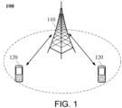
- the communication system 100 may include a network device 110, and the network device 110 may be an apparatus communicating with a terminal 120 (or referred to as a communication terminal or a terminal).
- the network device 110 may provide communication coverage for a specific geographic area and may communicate with a terminal located within the coverage area.
- the network device 110 may be a base station (base transceiver station, BTS) in the GSM system or the CDMA system, may also be a base station (NodeB or NB) in the WCDMA system, and may further be an evolutional base station (evolutional node B, eNB or eNodeB) in the LTE system, or a wireless controller in a cloud radio access network (CRAN).
- BTS base transceiver station
- NodeB or NB base station
- eNodeB evolutional base station
- eNodeB evolutional base station
- LTE long term evolutional base station
- CRAN cloud radio access network
- the network device may be a network device in a mobile switching center, a repeater station, an access point, a vehicle-mounted device, a wearable device, a hub, a switch, a bridge, a router, a network side device in a 5G network, or a public land mobile network (PLMN) that evolves in the future, and so on.
- PLMN public land mobile network
- the communication system 100 also includes at least one terminal 120 located within the coverage area of the network device 110.
- the "terminal" used herein includes, but not limited to, connection via a wired line (e.g., a public switched telephone network (PSTN), a digital subscriber line (DSL), a digital cable, or a direct cable), via another data connection/network, via a wireless interface (e.g., for a cellular network, a wireless local area network (WLAN), a digital television network such as a DVB-H network, a satellite network, or an AM-FM broadcast transmitter), via another terminal that is configured to receive/send a communication signal, and/or via an Internet of Things (IoT) apparatus.
- a wired line e.g., a public switched telephone network (PSTN), a digital subscriber line (DSL), a digital cable, or a direct cable
- PSTN public switched telephone network
- DSL digital subscriber line
- a digital cable e.g., a wireless local area
- a terminal that is configured to communicate through a wireless interface may be referred to as a "wireless communication terminal", a “wireless terminal”, or a “mobile terminal”.
- the mobile terminal include, but not limited to, a satellite or cellular phone; a personal communication system (PCS) terminal that may combine a cellular radio phone with data processing, facsimileing, and data communication capabilities, may include a radio phone, a pager, Internet/Intranet access, a web browser, a notepad, a calendar, and/or a personal digital assistant (PDA) of a global positioning system (GPS) receiver, may include a conventional laptop and/or a handheld receiver, or may include other electronic devices including a radio telephone transceiver.
- GPS global positioning system
- the terminal may refer to an access terminal, user equipment (UE), a user unit, a user station, a mobile station, a mobile platform, a remote station, a remote terminal, a mobile device, a user terminal, a terminal, a wireless communication device, a user agent, or a user device.
- the access terminal may be a cellular phone, a cordless phone, a session initiation protocol (SIP) phone, a wireless local loop (WLL) station, a PDA, a handheld device with wireless communication capabilities, a computing device or other processing devices connected to a wireless modem, a vehicle-mounted device, a wearable device, a terminal in a 5G network, or a terminal in a PLMN that may evolve in the future.
- SIP session initiation protocol
- WLL wireless local loop
- D2D communication may be performed between terminals 120.
- the 5G system or 5G network may also be referred to as a new radio (NR) system or NR network.
- NR new radio
- the communication system 100 may include a plurality of network devices, and the coverage area of each of the network devices may include terminals of other numbers, which is not limited in the embodiments of the disclosure.
- the communication system 100 may also include other network entities such as a network controller, a mobility management entity, etc., which is not limited in the embodiments of the disclosure.
- the communication apparatus may include the network device 110 and the terminals 120 having the communication function.
- the network device 110 and the terminals 120 may be the specific apparatuses described above, and description thereof is thus not repeated herein.
- the communication apparatus may further include other apparatuses in the communication system 100, such as other network entities including a network controller, a mobility management entity, etc., which is not limited in the embodiments of the disclosure.
- system and “network” in the specification are often used interchangeably in the specification.
- the term “and/or” in the specification is only an association relationship describing the associated objects, and it means that there may be three types of relationships. For instance, A and/or B may mean that: A exists alone, A and B exist at the same time, and B exists alone. Further, the character “/" in the specification generally indicates that the associated objects before and after are in an "or” relationship.
- RRC radio resource control
- a new RRC state that is, the RRC inactive (RRC_INACTIVE) state. This state is different from the RRC idle (RRC_IDLE) state and the RRC connected (RRC_CONNECTED) state.
- the three RRC states in the 5G network environment are described as follows.
- the following conditions trigger the UE to return to the idle state: 1) When the CN initial paging message is received; 2) When the RRC resume request is initiated, the timer T319 is started, if the timer expires; 3) MSG4 integrity protection verification fails; 4) When the cell is reselected to another radio access technology (RAT); 5) It enters the state of camping on any cell.
- RAT radio access technology
- the network side may configure the inactive state configuration parameters for the UE through RRC dedicated signaling (e.g., RRC release message), and the main configuration parameters include: 1) Inactive radio network temporary identification (I- RNTI), the I-RNTI is used to identify the UE inactive state context of the UE on the base station side, and the I-RNTI is unique within the base station. 2) RNA, RNA is used to control the area where the UE performs cell selection and reselection in the inactive state, and it is also the paging range area for the initial paging of the RAN.
- I- RNTI Inactive radio network temporary identification
- RNA is used to control the area where the UE performs cell selection and reselection in the inactive state, and it is also the paging range area for the initial paging of the RAN.
- RAN discontinuous reception cycle (RAN DRX cycle), the RAN DRX cycle is used to calculate the paging occasion of the RAN initial paging.
- RAN notification area update period (RNA update periodicity, RNAU periodicity), RNAU periodicity is configured to control the period of the UE to perform periodic RAN location update.
- NCC Next hop chaining counter
- the UE When the UE moves in the RNA area, it does not need to notify the network side and follows the mobility behavior in the idle state, that is, the principle of cell selection and reselection.
- the UE When the UE moves out of the paging area configured by the RAN, the UE may be triggered to resume the RRC connection and reacquire the paging area configured by the RAN.
- the base station that maintains the connection between the RAN and the CN for the UE may trigger all cells in the RAN paging area to send paging messages to the UE, so that the inactive UE may resume the RRC connection and receive data.
- the UE in the inactive state is configured with a RAN paging area, and in order to ensure the reachability of the UE in this area, the UE needs to perform periodic location updates according to the network configured period (based on the RNAU timer). Therefore, the scenarios that trigger the UE to execute RNAU include the timeout of the RNAU timer or the UE moving to an area outside the RNA.
- the anchor base station determines whether to transfer the context of the UE to the target base station side. Therefore, in general, the target base station may carry the cause value carried in the UE initiated RRC connection resume request message in the retrieve UE context message and sends it to the anchor base station, and the anchor base station determines whether to transfer the context of the UE to the target base station side. The following describes the context transfer of the UE in combination with the RNAU process.
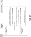
- FIG. 2A is a flow chart of RNAU with context transfer, and the following steps are included.
- FIG. 2B is a flow chart of RNAU without context transfer, and the following steps are included.
- the anchor base station in FIG 2A and FIG 2B refers to the base station that stores the UE context.
- the anchor base station is the base station that serves the UE last time.
- EDT data transmission is introduced in LTE, and during the EDT data transmission process, the UE may always remain in an idle state or a suspend state or an inactive state to complete uplink and/or downlink EDT data transmission.
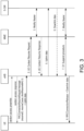
- the user plane transmission scheme may be adopted by EDT data transmission, and as shown in FIG. 3 , the following steps are included.
- the RRCConnectionRelease message carries the following information: releaseCause, releaseID, and NCC.
- LTE is taken as an example for illustration.
- NR is the same as LTE, and the difference therebetween is that for NR, eNB needs to be replaced with gNB, the mobility management entity (MME) needs to be replaced with AMF, and the serving gateway (S-GW) needs to be replaced with the user plane function (UPF) entity.
- MME mobility management entity
- S-GW serving gateway
- the RRC connection resume request message is carried in the MSG3 of the random access process, and the uplink data belongs to user plane data.
- the uplink data is transmitted in a dedicated transmission channel (DTCH)
- the RRC connection resume request message is transmitted in a common control channel (CCCH)
- a medium access control (MAC) service data unit (SDU) i.e., DTCH SDU
- a MAC SDU i.e., CCCH SDU
- PDU MAC protocol data unit
- the downlink is the same as the uplink, the downlink data is transmitted in the DTCH, the RRC connection release message is transmitted in the CCCH, the MAC SDU (i.e., DTCH SDU) corresponding to the downlink data and the MAC SDU (i.e., CCCH SDU) corresponding to the RRC connection release message are multiplexed in the same MAC PDU at the MAC layer.
- the uplink data or the downlink data in FIG. 3 may be packet data.
- the packet data is also referred to as small data, small data packet, or EDT data.
- the terminal For the transmission of the uplink packet data, only one packet data transmission is currently supported. However, in some scenarios, there may be several consecutive packet data transmissions. At this time, the terminal may only enter the connected state, and then after data is transmitted through the dedicated bearer, the terminal enters the idle state or the inactive state again, which increases signaling overhead and UE power consumption.
- the technical solution provided by the embodiments of the disclosure provides a new transmission method of packet data through which continuous transmission of a plurality of packet data is supported, the scenario of packet data transmission is expanded, EDT is widely applied, and signaling overhead and UE power consumption are further reduced.
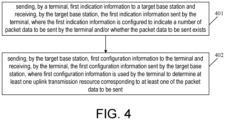
- FIG. 4 is a schematic flow chart of a data transmission method according to the claimed invention. As shown in FIG. 4 , the data transmission method includes the following steps.
- a terminal sends first indication information to a target base station, and the target base station receives the first indication information sent by the terminal.
- the first indication information is configured to indicate a number of packet data to be sent by the terminal and/or whether the packet data to be sent exists.
- the terminal may be any apparatus capable of communicating with the network, such as a mobile phone, a tablet computer, a notebook, a vehicle-mounted terminal, and a wearable apparatus.
- the terminal is a terminal in an inactive state.
- N N is a positive integer
- the terminal when the terminal is in an inactive state, N (N is a positive integer) pieces of packet data are required to be sent, and the terminal initiates a random access process. Specifically, the terminal sends an RRC resume request message to the target base station. During the random access process or after the random access process, the terminal sends the first indication information to the target base station. Through the first indication information, the target base station receives the indication of the number of the packet data to be sent by the terminal (that is, how many pieces of the packet data that the terminal has to send), and/or whether the packet data to be sent exists(that is, whether there is any subsequently packet data to be sent).
- the random access process initiated by the terminal may be a contention-based 2-step random access process (hereinafter referred to as the 2-step random access process), or a contention-based 4-step random access process (hereinafter referred to as the 4 step random access process).
- the 2-step random access process a contention-based 2-step random access process
- the 4 step random access process a contention-based 4-step random access process
- the 4-step random access includes the following steps: (1) The UE sends MSG1 to the base station. (2) The base station sends MSG2 to the UE. (3) The UE sends MSG3 to the base station. (4) The base station sends MSG4 to the UE.
- the MSGA in the 2-step random access process may be obtained
- the MSGB in the 2-step random access process may be obtained. It thus can be seen that the 2-step random access includes the following steps: (1) The UE sends MSGA to the base station. (2) The base station sends MSGB to the UE.
- the implementation of the first indication information is achieved by adopting the following method one or a combination of method one with any multiple methods.
- Method one The terminal sends a first preamble to the target base station on a first physical random access channel (PRACH) resource.
- the target base station receives the first preamble sent by the terminal on the first PRACH resource.
- the first PRACH resource and/or the first preamble have/has an association relationship with the number of the packet data to be sent by the terminal.
- the target base station determines the number of the packet data to be sent by the terminal according to the first PRACH resource and/or the first preamble.
- the association relationship is configured through second configuration information.
- the target base station sends the second configuration information to the terminal, and the terminal receives the second configuration information sent by the target base station.
- the second configuration information is used by the terminal to determine the association relationship between the number of the packet data to be sent and the first PRACH resource and/or the first preamble. Based on the above, the terminal determines (or selects) the first PRACH resource and/or the first preamble based on the second configuration information and the number of the packet data to be sent.
- the second configuration information is configured through a system broadcasting message or dedicated signaling.
- Method two The terminal sends a first message to the target base station, and the target base station receives the first message sent by the terminal.
- the first message carries the first indication information.
- the first message is the MSG3 in the 4-step random access process, or the first message is the MSGA in the 2-step random access process.
- the first indication information is carried in a payload in the MSGA.
- Method three The terminal sends uplink data or uplink signaling to the target base station, and the target base station receives the uplink data or the uplink signaling sent by the terminal.
- the MAC SDU corresponding to the uplink data or the uplink signaling is multiplexed with a first MAC control element (CE) in the same MAC PDU, and the first MAC CE carries the first indication information.
- CE MAC control element
- the first MAC CE is a newly defined uplink MAC CE, and the uplink MAC CE carries the first indication information.
- Method four The terminal sends uplink data or uplink signaling to the target base station, and the target base station receives the uplink data or the uplink signaling sent by the terminal.
- the MAC SDU corresponding to the uplink data or the uplink signaling is multiplexed with a second MAC CE in the same MAC PDU, and the second MAC CE carries a buffer status report (BSR).
- BSR indicates that the packet data to be sent exists and/or the number of the packet data to be sent.
- the second MAC CE is an existing MAC CE called a BSR MAC CE
- the BSR in the BSR MAC CE indicates that the packet data to be sent exitst and/or the number of the packet data to be sent.
- Method five The terminal sends a first data packet to the target base station, and the target base station receives the first data packet sent by the terminal.
- a packet header of the first data packet carries the first indication information.
- the packet header is a packet data convergence protocol (PDCP) packet header or an radio link control (RLC) packet header.
- PDCP packet data convergence protocol
- RLC radio link control
- Method six The terminal sends a control PDU to the target base station, and the target base station receives the control PDU sent by the terminal.
- the control PDU carries the first indication information. Further, the control PDU is a PDCP control PDU or an RLC control PDU.
- the target base station receives an RRC resume request message sent by the terminal.
- the target base station obtains a first terminal identifier (e.g., I-RNTI) from the RRC resume request message, addresses an anchor base station according to the first terminal identifier, and sends a retrieve terminal context request message to the anchor base station.
- a first terminal identifier e.g., I-RNTI
- the anchor base station determines to send the context of the terminal to the target base station
- the target base station resumes the context of the terminal
- the anchor base station determines not to send the context of the terminal to the target base station
- the anchor base station resumes the context of the terminal.
- the RRC resume request message is carried in the MSG3 of the 4-step random access process, or the RRC resume request message is carried in the MSGA of the 2-step random access process.
- the target base station After receiving the RRC resume request message, the target base station decodes the message and obtains the identifier of the UE (i.e., I-RNTI). The target base station addresses the anchor base station according to the I-RNTI, and sends a RETRIEVE UE CONTEXT REQUEST message to the anchor base station. 2) The anchor base station determines whether to relocate the UE context, and if it determines to relocate the UE context, the anchor base station replies to the RETRIEVE UE CONTEXT RESPONSE message sent by the target base station and transfers the UE context to the target base station.
- I-RNTI the identifier of the UE
- the anchor base station replies to the target base station with a RETRIEVE UE CONTEXT FAILURE message. 3) If the UE context is relocated, the target base station resumes the UE context (such as resuming security, resuming a data radio bearer (DRB) configuration, resuming an Signaling Radio Bearer (SRB) configuration, etc.) after receiving the UE context sent by the anchor base station. If the UE context is not relocated, the anchor base station resumes the UE context (such as resuming security, resuming the DRB configuration, resuming the SRB configuration, etc.).
- DRB data radio bearer
- SRB Signaling Radio Bearer
- the target base station sends first configuration information to the terminal, and the terminal receives the first configuration information sent by the target base station.
- the first configuration information is used by the terminal to determine at least one uplink transmission resource corresponding to at least one of the packet data to be sent.
- implementation of the first configuration information may be achieved by adopting any one of the following methods.
- the target base station sends a static configuration instruction to the terminal, and the terminal receives the static configuration instruction sent by the target base station.
- the static configuration instruction carries the first configuration information.
- the static configuration instruction is an RRC message, the RRC message is the MSG4 in the 4-step random access process, or the RRC message is the MSGB in the 2-step random access process.
- the target base station uses a pre-configuration method to configure one or more uplink transmission resources (i.e., uplink grant) for the terminal.
- one or more uplink transmission resources i.e., uplink grant
- the target base station sends a dynamic scheduling instruction to the terminal, and the terminal receives the dynamic scheduling instruction sent by the target base station.
- the dynamic scheduling instruction carries the first configuration information. Further, the dynamic scheduling instruction is downlink control information (DCI).
- DCI downlink control information
- the target base station uses a dynamic scheduling method to schedule one or more UL grants for the terminal.
- method I) and method II) in step 402 may be implemented in any combination with method one to method six in step 401.
- the UL grant may be scheduled by adopting method I) or method II).
- the UL grant may be scheduled by adopting method II).
- the uplink transmission resource refers to a physical uplink shared channel (PUSCH) resource.
- the target base station may configure a corresponding relationship between a preamble and the PUSCH, and the corresponding relationship may be one preamble corresponding to one or more PUSCHs. In this way, if there are multiple pieces of the packet data to be sent by the terminal, multiple PUSCH resources may be selected to send the packet data.
- the terminal in the embodiments of the disclosure is in an inactive state when sending the packet data, that is, the UL grant scheduled by the target base station is used by the terminal in the inactive state to send the packet data.
- the UL grant and packet data transmission are described as follows in combination with FIG. 5A and FIG. 5B .
- the target base station sends a retrieve UE context request message to the anchor base station.
- the anchor base station determines to relocate the UE context and replies to the target base station with a retrieve UE context response message.
- the target base station resumes the UE context and initiates a path conversion process to the AMF.
- the target base station sends a UL grant to the UE, and the UE sends uplink data based on the UL grant.
- the uplink data refers to packet data.
- the target base station may send the UL grant to the UE multiple times, so that the UE may continuously send multiple uplink data. 6.
- the target base station sends an RRC connection release message to the UE.
- the following process flow is included. 1.
- the target base station sends a retrieve UE context request message to the anchor base station. 3.
- the anchor base station determines to relocate the UE context and replies to the target base station with a retrieve UE context response message. 4.
- the target base station resumes the UE context and initiates a path conversion process to the AMF. 5.
- the target base station sends an RRC connection release message to the UE. 6.
- the target base station sends a UL grant to the UE, and the UE sends uplink data based on the UL grant.
- the uplink data refers to packet data.
- the target base station may send the UL grant to the UE multiple times, so that the UE may continuously send multiple uplink data.
- the target base station dynamically schedules the UL grant to the terminal multiple times.
- the embodiments of the disclosure are not limited thereto, and the target base station may also schedule multiple UL grants to the terminal at a time, that is, the target base station configures one or more UL grants for the terminal at a time in a pre-configuration manner.
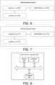
- FIG. 6 is a first schematic view of a structure forming a data transmission apparatus according to the claimed invention, and as shown in FIG. 6 , the data transmission apparatus includes a receiving circuit 601 and a sending circuit 602.
- the receiving circuit 601 is configured to receive first indication information sent by a terminal.
- the first indication information is configured to indicate a number of the packet data to be sent by the terminal and/or whether the packet data to be sent exists.
- the sending circuit 602 is configured to send first configuration information to the terminal.
- the first configuration information is used by the terminal to determine at least one uplink transmission resource corresponding to at least one of the packet data to be sent.
- the receiving circuit 601 is configured to receive a first preamble sent by the terminal on a first PRACH resource, and the first PRACH resource and/or the first preamble have/has an association relationship with the number of the packet data to be sent by the terminal.
- the device further includes a determination circuit 603 configured to determine the number of the packet data to be sent by the terminal according to the first PRACH resource and/or the first preamble.
- the sending circuit 602 is configured to send second configuration information to the terminal, and the second configuration information is used by the terminal to determine the association relationship between the number of the packet data to be sent and the first PRACH resource and/or the first preamble.
- the second configuration information is configured through a system broadcasting message or dedicated signaling.
- the receiving circuit 601 is configured to receive a first message sent by the terminal, and the first message carries the first indication information.
- the first message is the MSG3 in the 4-step random access process, or the first message is the MSGA in the 2-step random access process.
- the receiving circuit 601 is configured to receive uplink data or uplink signaling sent by the terminal, and a MAC SDU corresponding to the uplink data or the uplink signaling is multiplexed with a first MAC CE in a same MAC PDU, and the first MAC CE carries the first indication information.
- the receiving circuit 601 is configured to receive uplink data or uplink signaling sent by the terminal, a MAC SDU corresponding to the uplink data or the uplink signaling is multiplexed with a second MAC CE in a same MAC PDU, and the second MAC CE carries a BSR, and The BSR indicates that the packet data to be sent exits and/or the number of the packet data to be sent.
- the receiving circuit 601 is configured to receive a first data packet sent by the terminal, and a packet header of the first data packet carries the first indication information.
- the packet header is a PDCP packet header or an RLC packet header.
- the receiving circuit 601 is configured to receive a control PDU sent by the terminal, and the control PDU carries the first indication information.
- control PDU is a PDCP control PDU or an RLC control PDU.
- the sending circuit 602 is configured to send a static configuration instruction to the terminal, and the static configuration instruction carries the first configuration information.
- the static configuration instruction is an RRC message
- the RRC message is the MSG4 in the 4-step random access process
- the RRC message is the MSGB in the 2-step random access process.
- the sending circuit 602 is configured to send a dynamic scheduling instruction to the terminal, and the dynamic scheduling instruction carries the first configuration information.
- the dynamic scheduling instruction is DCI.
- the receiving circuit 601 is configured to receive an RRC resume request message sent by the terminal.
- the receiving circuit 601 is configured to obtain a first terminal identifier from the RRC resume request message, address an anchor base station according to the first terminal identifier, and send a retrieve terminal context request message to the anchor base station.
- the anchor base station determines to send the context of the terminal to a target base station, the target base station resumes the context of the terminal, and if the anchor base station determines not to send the context of the terminal to the target base station, the anchor base station resumes the context of the terminal.
- the RRC resume request message is carried in the MSG3 of the 4-step random access process, or the RRC resume request message is carried in the MSGA of the 2-step random access process.
- FIG. 7 is a second schematic view of a structure forming a data transmission apparatus provided by an embodiment of the disclosure, and as shown in FIG. 7 , the data transmission apparatus includes a receiving circuit 701 and a sending circuit 702.
- the sending circuit 701 is configured to send first indication information to a target base station.
- the first indication information is configured to indicate a number of the packet data to be sent by the terminal and/or whether the packet data to be sent exists.
- the receiving circuit 602 is configured to receive first configuration information sent by the target base station.
- the first configuration information is used by the terminal to determine at least one uplink transmission resource corresponding to at least one packet data to be sent.
- the sending circuit 701 is configured to send a first preamble to the target base station on a first PRACH resource, and the first PRACH resource and/or the first preamble have/has an association relationship with the number of the packet data to be sent by the terminal.
- the receiving circuit 702 is configured to receive second configuration information sent by the target base station, and the second configuration information is used by the terminal to determine the association relationship between the number of the packet data to be sent and the first PRACH resource and/or the first preamble.
- the device further includes a determination circuit 703 configured to determine the first PRACH resource and/or the first preamble based on the second configuration information and the number of the packet data to be sent.
- the second configuration information is configured through a system broadcasting message or dedicated signaling.
- the sending circuit 701 is configured to send a first message to the target base station, and the first message carries the first indication information.
- the first message is the MSG3 in the 4-step random access process, or the first message is the MSGA in the 2-step random access process.
- the sending circuit 701 is configured to send uplink data or uplink signaling to the target base station, a MAC SDU corresponding to the uplink data or the uplink signaling is multiplexed with a first MAC CE in a same MAC PDU, and the first MAC CE carries the first indication information.
- the sending circuit 701 is configured to send uplink data or uplink signaling to the target base station, a MAC SDU corresponding to the uplink data or the uplink signaling is multiplexed with a second MAC CE in a same MAC PDU, and the second MAC CE carries a BSR, and the BSR indicates that the packet data to be sent exists and/or the number of the packet data to be sent.
- the sending circuit 701 is configured to send a first data packet to the target base station, and a packet header of the first data packet carries the first indication information.
- the packet header is a PDCP packet header or an RLC packet header.
- the sending circuit 701 is configured to send a control PDU to the target base station, and the control PDU carries the first indication information.
- control PDU is a PDCP control PDU or an RLC control PDU.
- the receiving circuit 702 is configured to receive a static configuration instruction sent by the target base station, and the static configuration instruction carries the first configuration information.
- the static configuration instruction is an RRC message
- the RRC message is the MSG4 in the 4-step random access process
- the RRC message is the MSGB in the 2-step random access process.
- the receiving circuit 702 is configured to receive a dynamic scheduling instruction sent by the target base station, and the dynamic scheduling instruction carries the first configuration information.
- the dynamic scheduling instruction is DCI.
- FIG. 8 is a schematic view of a structure of a communication apparatus 800 provided by an embodiment of the disclosure.
- the communication apparatus may be a terminal or a network device (e.g., a base station).
- the communication apparatus 800 shown in FIG. 8 includes a processor 810, and the processor 810 may call and run a computer program from a memory to implement the method in the embodiments of the disclosure.
- the communication apparatus 800 may further include a memory 820.
- the processor 810 may call and run a computer program from the memory 820 to implement the method in the embodiments of the disclosure.
- the memory 820 may be a separate device independent of the processor 810 or may be integrated in the processor 810.
- the communication apparatus 800 may further include a transceiver 830, and the processor 810 may control the transceiver 830 to communicate with other apparatuses. Specifically, it can send information or data to other apparatuses, or receive information or data sent by other apparatuses.
- the transceiver 830 may include a transmitter and a receiver.
- the transceiver 830 may further include an antenna, and a number of antennas may be one or more.
- the communication apparatus 800 may specifically be a network device in the embodiments of the disclosure, and the communication apparatus 800 may implement the corresponding process flows implemented by the network device in the various methods in the embodiments of the disclosure.
- the communication apparatus 800 may implement the corresponding process flows implemented by the network device in the various methods in the embodiments of the disclosure.
- description thereof is not repeated herein.
- the communication apparatus 800 may specifically be a mobile terminal/terminal in the embodiments of the disclosure, and the communication apparatus 800 may implement the corresponding process flows implemented by the mobile terminal/terminal in the various methods in the embodiments of the disclosure.
- description thereof is not repeated herein.
- FIG. 9 is a schematic view of a structure of a chip provided by an embodiment of the disclosure.
- a chip 900 shown in FIG. 9 includes a processor 910, and the processor 910 may call and run a computer program from a memory to implement the method in the embodiments of the disclosure.
- the chip 900 may further include a memory 920.
- the processor 910 may call and run a computer program from the memory 920 to implement the method in the embodiments of the disclosure.
- the memory 920 may be a separate device independent of the processor 910 or may be integrated in the processor 910.
- the chip 900 may further include an input interface 930.
- the processor 910 may control the input interface 930 to communicate with other apparatuses or chips, and specifically, may obtain information or data sent by other apparatuses or chips.
- the chip 900 may further include an output interface 940.
- the processor 910 may control the output interface 940 to communicate with other apparatuses or chips, and specifically, may output information or data to other apparatuses or chips.
- the chip may be applied to the network device in the embodiments of the disclosure, and the chip may implement the corresponding process flows implemented by the network device in the various methods in the embodiments of the disclosure.
- description thereof is not repeated herein.
- the chip may be applied to the mobile terminal/terminal in the embodiments of the disclosure, and the chip may implement the corresponding process flows implemented by the mobile terminal/terminal in the various methods in the embodiments of the disclosure.
- description thereof is not repeated herein.
- the chip mentioned in the embodiments of the disclosure may also be referred to as a system-level chip or a system on a chip.
- FIG. 10 is a schematic block view of a communication system 1000 provided by an embodiment of the disclosure. As shown in FIG. 10 , the communication system 1000 includes a terminal 1010 and a network device 1020.
- the terminal 1010 may be used to implement the corresponding functions implemented by the terminal in the foregoing method
- the network device 1020 may be used to implement the corresponding functions implemented by the network device in the foregoing method.
- description thereof is not repeated herein.
- the processor of the embodiments of the disclosure may be an integrated circuit chip with signal processing capability.
- the steps of the foregoing method in the embodiments may be completed by an integrated logic circuit of hardware or an instruction in the form of software in the processor.
- the processor may be a general-purpose processor, a digital signal processor (DSP), an application specific integrated circuit (ASIC), a field programmable gate array (FPGA), or other components such as a programmable logic device, a discrete gate, a transistor logic device, and a discrete hardware component.
- the processor may implement or execute various methods, steps, and logical block diagrams disclosed in the embodiments of the disclosure.
- the general-purpose processor may be a microprocessor, or the processor may be any conventional processor and the like.
- the steps of the method disclosed in the embodiments of the disclosure may be directly implemented as being executed and completed by a hardware decoding processor, or may be executed and completed by a combination of hardware and software modules in a decoding processor.
- the software module may be located in a mature storage medium in the art, such as a random access memory, a flash memory, a read-only memory, a programmable read-only memory, an electrically erasable programmable memory, or a register.
- the storage medium is located in the memory, and the processor reads the information in the memory and completes the steps of the foregoing method in combination with its hardware.
- the memory in the embodiments of the disclosure may be a volatile memory or a non-volatile memory or may include both the volatile memory and the non-volatile memory.
- the non-volatile memory may be a ready-only memory (ROM), a programmable ROM (PROM), an erasable PROM (EPROM), an electrically EPROM (EEPROM), or a flash memory.
- the volatile memory may be a random access memory (RAM) used as an external cache.
- RAM random access memory
- DRAM dynamic RAM
- SDRAM synchronous DRAM
- DDR SDRAM double data rate SDRAM
- ESDRAM enhanced SDRAM
- SLDRAM synchlink DRAM
- DRRAM direct rambus RAM
- the memory in the embodiments of the disclosure may also be a static RAM (SRAM), a dynamic RAM (DRAM), a synchronous DRAM (SDRAM), a double data rate SDRAM (DDR SDRAM), an enhanced SDRAM (ESDRAM), a synch link DRAM (SLDRAM), and a direct rambus RAM (DRRAM) and the like. That is, the memory in the embodiments of the disclosure is intended to include, but not limited to, these and any other suitable types of memory.
- SRAM static RAM
- DRAM dynamic RAM
- SDRAM synchronous DRAM
- DDR SDRAM double data rate SDRAM
- ESDRAM enhanced SDRAM
- SLDRAM synch link DRAM
- DRRAM direct rambus RAM
- the embodiments of the disclosure further provides a computer-readable storage medium configured for storing a computer program.
- the computer-readable storage medium may be applied to the network device in the embodiments of the disclosure, and the computer program causes a computer to execute the corresponding process flows implemented by the network device in the various methods of the embodiments of the disclosure.
- description thereof is not repeated herein.
- the computer-readable storage medium may be applied to the mobile terminal/terminal in the embodiments of the disclosure, and the computer program causes a computer to execute the corresponding process flows implemented by the mobile terminal/terminal in the various methods of the embodiments of the disclosure.
- description thereof is not repeated herein.
- the embodiments of the disclosure further provides a computer program product including a computer program instruction.
- the computer program product may be applied to the network device in the embodiments of the disclosure, and the computer program instruction causes the computer to execute the corresponding process flows implemented by the network device in the various methods of the embodiments of the disclosure.
- description thereof is not repeated herein.
- the computer program product may be applied to the mobile terminal/terminal in the embodiments of the disclosure, and the computer program instruction causes a computer to execute the corresponding process flows implemented by the mobile terminal/terminal in the various methods of the embodiments of the disclosure.
- description thereof is not repeated herein.
- the embodiments of the disclosure further provides a computer program.
- the computer program may be applied to the network device in the embodiments of the disclosure, and when running on a computer, the computer program causes the computer to execute the corresponding process flows implemented by the network device in the various methods of the embodiments of the disclosure.
- the computer program causes the computer to execute the corresponding process flows implemented by the network device in the various methods of the embodiments of the disclosure.
- description thereof is not repeated herein.
- the computer program may be applied to the mobile terminal/terminal in the embodiments of the disclosure, and when running on a computer, the computer program causes the computer to execute the corresponding process flows implemented by the mobile terminal/terminal in the various methods of the embodiments of the disclosure.
- the computer program may be applied to the mobile terminal/terminal in the embodiments of the disclosure, and when running on a computer, the computer program causes the computer to execute the corresponding process flows implemented by the mobile terminal/terminal in the various methods of the embodiments of the disclosure.
- description thereof is not repeated herein.
- the disclosed system, device, and method may be implemented in other ways.
- the device embodiments described above are only illustrative.
- the division of the unit is only a logical function division, and there may be other division methods in actual implementation.
- multiple units or components may be combined or integrated into another system, or some features may be omitted or may not be implemented.
- the displayed or discussed mutual coupling or direct coupling or communication connection may be implemented through some interfaces, and the indirect coupling or communication connection of the device or unit may be in electrical, mechanical, or other forms.
- the units described as separate components may or may not be physically separated, and the components displayed as units may or may not be physical units, that is, they may be located in one place, or they may be distributed on multiple network units. Some or all of the units may be selected according to actual needs to achieve the objectives of the solutions of the embodiments.
- each functional unit may be integrated into one processing unit, or each unit may exist alone physically, or two or more units may be integrated into one unit.
- the function is implemented in the form of a software functional unit and sold or used as an independent product, it may be stored in a computer-readable storage medium.
- the computer software product is stored in a storage medium and includes a number of instructions to enable a computer apparatus (which may be a personal computer, a server, or a network device and the like) to execute all or part of the steps of the method described in the various embodiments of the disclosure.
- the aforementioned storage medium includes a U disk, a mobile hard disk, a read-only memory (ROM), a random access memory (RAM), a magnetic disk, an optical disk, or other media that may store program codes.
Landscapes
- Engineering & Computer Science (AREA)
- Computer Networks & Wireless Communication (AREA)
- Signal Processing (AREA)
- Mobile Radio Communication Systems (AREA)
Claims (13)
- Datenübertragungsverfahren, umfassend:Empfangen (401), durch eine Ziel-Basisstation, einer ersten Anzeigeinformation von einem Endgerät, wobei die erste Anzeigeinformation dafür ausgelegt ist, eine Anzahl von durch das Endgerät zu sendenden Paketdaten anzuzeigen und/oder anzuzeigen, ob die zu sendenden Paketdaten existieren; undSenden (402), durch die Ziel-Basisstation, einer ersten Konfigurationsinformation an das Endgerät, wobei die erste Konfigurationsinformation durch das Endgerät verwendet wird, um mindestens eine Uplink-Übertragungsressource zu bestimmen, die mindestens einem der zu sendenden Paketdaten entspricht,wobei der Schritt des Empfangens, durch die Ziel-Basisstation, der ersten Anzeigeinformation vom Endgerät Folgendes umfasst:Empfangen, durch die Ziel-Basisstation, einer ersten Präambel vom Endgerät auf einer ersten PRACH(Physical Random Access Channel, physikalischer Direktzugriffskanal)-Ressource, wobei die erste PRACH-Ressource und/oder die erste Präambel eine Assoziationsbeziehung mit der Anzahl der vom Endgerät zu empfangenden Paketdaten hat/haben; undBestimmen, durch die Ziel-Basisstation, der Anzahl der vom Endgerät zu empfangenden Paketdaten gemäß der ersten PRACH-Ressource und/oder der ersten Präambel;wobei das Verfahren ferner Folgendes umfasst:Senden, durch die Ziel-Basisstation, einer zweiten Anzeigeinformation an das Endgerät, wobei die zweite Konfigurationsinformation durch das Endgerät verwendet wird, um die Assoziationsbeziehung zwischen der Anzahl der an die Ziel-Basisstation zu sendenden Paketdaten und der ersten PRACH-Ressource und/oder der ersten Präambel zu bestimmen;wobei die zweite Konfigurationsinformation durch eine System-Rundrufnachricht oder dedizierte Signalisierung konfiguriert wird.
- Verfahren gemäß Anspruch 1, wobei der Schritt des Empfangens, durch die Ziel-Basisstation, der ersten durch das Endgerät gesendeten Anzeigeinformation ferner Folgendes umfasst:Empfangen, durch die Ziel-Basisstation, einer ersten durch das Endgerät gesendeten Nachricht, wobei die erste Nachricht die erste Anzeigeinformation enthält;wobei die erste Nachricht MSG3 in einem 4-schrittigen Direktzugriffsverfahren ist oder die erste Nachricht MSGA in einem 2-schrittigen Direktzugriffsverfahren ist.
- Verfahren gemäß Anspruch 1, wobei der Schritt des Empfangens, durch die Ziel-Basisstation, der ersten durch das Endgerät gesendeten Anzeigeinformation ferner Folgendes umfasst:
Empfangen, durch die Ziel-Basisstation, der durch das Endgerät gesendeten Uplink-Daten oder Uplink-Signalisierung, wobei eine MAC(Media Access Control, Medienzugriffssteuerung)-Dienstdateneinheit (SDU, Service Data Unit), die den Uplink-Daten oder der Uplink-Signalisierung entspricht, mit einem ersten MAC-Steuerelement (CE, Control Element) in einer gleichen MAC-Protokolldateneinheit (PDU, Protocol Data Unit) gemultiplext wird und das erste MAC-CE die erste Anzeigeinformation enthält. - Verfahren gemäß Anspruch 1, wobei der Schritt des Empfangens, durch die Ziel-Basisstation, der ersten durch das Endgerät gesendeten Anzeigeinformation ferner Folgendes umfasst:
Empfangen, durch die Ziel-Basisstation, der durch das Endgerät gesendeten Uplink-Daten oder Uplink-Signalisierung, wobei eine MAC-SDU, die den Uplink-Daten oder der Uplink-Signalisierung entspricht, mit einem zweiten MAC-CE in einer gleichen MAC-PDU gemultiplext wird, das zweite MAC-CE einen Pufferstatusbericht (BSR, Buffer Status Report) enthält und der BSR anzeigt, dass die zu sendenden Paketdaten existieren, und/oder die Anzahl der zu sendenden Paketdaten anzeigt. - Verfahren gemäß Anspruch 1, wobei der Schritt des Empfangens, durch die Ziel-Basisstation, der ersten durch das Endgerät gesendeten Anzeigeinformation ferner Folgendes umfasst:Empfangen, durch die Ziel-Basisstation, eines ersten durch das Endgerät gesendeten Datenpakets, wobei ein Paketkopf des ersten Datenpakets die erste Anzeigeinformation enthält;wobei der Paketkopf ein PDCP(Packet Data Convergence Protocol, Paketdatenkonvergenzprotokoll)-Paketkopf oder ein RLC(Radio Link Control, Funkverbindungssteuerung)-Paketkopf ist.
- Verfahren gemäß Anspruch 1, wobei der Schritt des Empfangens, durch die Ziel-Basisstation, der ersten durch das Endgerät gesendeten Anzeigeinformation Folgendes umfasst:Empfangen, durch die Ziel-Basisstation, einer durch das Endgerät gesendeten Steuer-PDU, wobei die Steuer-PDU die erste Anzeigeinformation enthält;wobei die Steuer-PDU eine PDCP-Steuer-PDU oder eine RLC-Steuer-PDU ist.
- Datenübertragungsverfahren, umfassend:Senden (401), durch ein Endgerät, einer ersten Anzeigeinformation an eine Ziel-Basisstation, wobei die erste Anzeigeinformation dafür ausgelegt ist, eine Anzahl von durch das Endgerät zu sendenden Paketdaten anzuzeigen und/oder anzuzeigen, ob die zu sendenden Paketdaten existieren; undEmpfangen (402), durch das Endgerät, einer ersten Konfigurationsinformation von der Ziel-Basisstation, wobei die erste Konfigurationsinformation durch das Endgerät verwendet wird, um mindestens eine Uplink-Übertragungsressource zu bestimmen, die mindestens einem der zu sendenden Paketdaten entspricht,wobei der Schritt des Sendens, durch das Endgerät, der ersten Anzeigeinformation an die Ziel-Basisstation Folgendes umfasst:Senden, durch das Endgerät, einer ersten Präambel an die Ziel-Basisstation auf einer ersten PRACH(Physical Random Access Channel, physikalischer Direktzugriffskanal)-Ressource, wobei die erste PRACH-Ressource und/oder die erste Präambel eine Assoziationsbeziehung mit der Anzahl der durch das Endgerät zu sendenden Paketdaten hat/haben; undwobei das Verfahren ferner Folgendes umfasst:Empfangen, durch das Endgerät, einer zweiten Konfigurationsinformation von der Ziel-Basisstation,wobei die zweite Konfigurationsinformation durch das Endgerät verwendet wird, um die Assoziationsbeziehung zwischen der Anzahl der zu sendenden Paketdaten und der ersten PRACH-Ressource und/oder der ersten Präambel zu bestimmen; undBestimmen, durch das Endgerät, der ersten PRACH-Ressource und/oder der ersten Präambel basierend auf der zweiten Konfigurationsinformation und der Anzahl der an die Ziel-Basisstation zu sendenden Paketdaten;wobei die zweite Konfigurationsinformation durch eine System-Rundrufnachricht oder dedizierte Signalisierung konfiguriert wird.
- Verfahren gemäß Anspruch 7, wobei der Schritt des Sendens der ersten Anzeigeinformation an die Ziel-Basisstation durch das Endgerät ferner Folgendes umfasst:Senden, durch das Endgerät, einer ersten Nachricht an die Ziel-Basisstation, wobei die erste Nachricht die erste Anzeigeinformation enthält;wobei die erste Nachricht MSG3 in einem 4-schrittigen Direktzugriffsverfahren ist oder die erste Nachricht MSGA in einem 2-schrittigen Direktzugriffsverfahren ist.
- Verfahren gemäß Anspruch 7, wobei der Schritt des Sendens, durch das Endgerät, der ersten Anzeigeinformation an die Ziel-Basisstation ferner Folgendes umfasst:
Senden, durch das Endgerät, von Uplink-Daten oder Uplink-Signalisierung an die Ziel-Basisstation, wobei eine MAC(Media Access Control, Medienzugriffssteuerung)-Dienstdateneinheit (SDU, Service Data Unit), die den Uplink-Daten oder der Uplink-Signalisierung entspricht, mit einem ersten MAC-Steuerelement (CE, Control Element) in einer gleichen MAC-Protokolldateneinheit (PDU, Protocol Data Unit) gemultiplext wird und das erste MAC-CE die erste Anzeigeinformation enthält. - Verfahren gemäß Anspruch 7, wobei der Schritt des Sendens, durch das Endgerät, der ersten Anzeigeinformation an die Ziel-Basisstation ferner Folgendes umfasst:
Senden, durch das Endgerät, von Uplink-Daten oder Uplink-Signalisierung an die Ziel-Basisstation, wobei eine MAC-SDU, die den Uplink-Daten oder der Uplink-Signalisierung entspricht, mit einem zweiten MAC-CE in einer gleichen MAC-PDU gemultiplext wird, das zweite MAC-CE einen Pufferstatusbericht (BSR, Buffer Status Report) enthält und der BSR anzeigt, dass die zu sendenden Paketdaten existieren, und/oder die Anzahl der zu sendenden Paketdaten anzeigt. - Verfahren gemäß Anspruch 8, wobei der Schritt des Sendens, durch das Endgerät, der ersten Anzeigeinformation an die Ziel-Basisstation ferner Folgendes umfasst:Senden, durch das Endgerät, eines ersten Datenpakets an die Ziel-Basisstation, wobei ein Paketkopf des ersten Datenpakets die erste Anzeigeinformation enthält;wobei der Paketkopf ein PDCP(Packet Data Convergence Protocol, Paketdatenkonvergenzprotokoll)-Paketkopf oder ein RLC(Radio Link Control, Funkverbindungssteuerung)-Paketkopf ist.
- Verfahren gemäß Anspruch 8, wobei der Schritt des Sendens, durch das Endgerät, der ersten Anzeigeinformation an die Ziel-Basisstation ferner Folgendes umfasst:Senden, durch das Endgerät, einer Steuer-PDU an die Ziel-Basisstation, wobei die Steuer-PDU die erste Anzeigeinformation enthält;wobei die Steuer-PDU eine PDCP-Steuer-PDU oder eine RLC-Steuer-PDU ist.
- Basisstationseinrichtung, umfassend:eine Empfangsschaltung (601), die dafür ausgelegt ist, eine erste Anzeigeinformation von einem Endgerät zu empfangen, wobei die erste Anzeigeinformation dafür ausgelegt ist, eine Anzahl von zu empfangenden Paketdaten vom Endgerät anzuzeigen und/oder anzuzeigen, ob die zu sendenden Paketdaten existieren; undeine Sendeschaltung (602), die dafür ausgelegt ist, die erste Konfigurationsinformation an das Endgerät zu senden, wobei die erste Konfigurationsinformation durch das Endgerät verwendet wird, um mindestens eine Uplink-Übertragungsressource zu bestimmen, die mindestens einem der zu sendenden Paketdaten entspricht,wobei die Empfangsschaltung (601) Folgendes durchführt:Empfangen einer ersten Präambel vom Endgerät auf einer ersten PRACH(Physical Random Access Channel,physikalischer Direktzugriffskanal)-Ressource, wobei die erste PRACH-Ressource und/oder die erste Präambel eine Assoziationsbeziehung mit der Anzahl der durch das Endgerät zu sendenden Paketdaten hat/haben; undBestimmen der Anzahl der vom Endgerät zu empfangenden Datenpakete gemäß der ersten PRACH-Ressource und/oder der ersten Präambel;wobei die Sendeschaltung (602) ferner folgendes durchführt:Senden einer zweiten Konfigurationsinformation an das Endgerät, wobei die zweite Konfigurationsinformation durch das Endgerät verwendet wird, um die Assoziationsbeziehung zwischen der Anzahl der an die Ziel-Basisstation zu sendenden Paketdaten und der ersten PRACH-Ressource und/oder der ersten Präambel zu bestimmen;wobei die zweite Konfigurationsinformation durch eine System-Rundrufnachricht oder dedizierte Signalisierung konfiguriert wird.
Applications Claiming Priority (1)
| Application Number | Priority Date | Filing Date | Title |
|---|---|---|---|
| PCT/CN2019/094714 WO2021000320A1 (zh) | 2019-07-04 | 2019-07-04 | 一种数据传输方法及装置、网络设备、终端 |
Publications (3)
| Publication Number | Publication Date |
|---|---|
| EP3962230A1 EP3962230A1 (de) | 2022-03-02 |
| EP3962230A4 EP3962230A4 (de) | 2022-04-27 |
| EP3962230B1 true EP3962230B1 (de) | 2024-08-28 |
Family
ID=74100133
Family Applications (1)
| Application Number | Title | Priority Date | Filing Date |
|---|---|---|---|
| EP19935904.3A Active EP3962230B1 (de) | 2019-07-04 | 2019-07-04 | Verfahren und vorrichtung zur datenübertragung sowie netzwerkvorrichtung und endgerät |
Country Status (4)
| Country | Link |
|---|---|
| US (1) | US20220070945A1 (de) |
| EP (1) | EP3962230B1 (de) |
| CN (2) | CN115767783B (de) |
| WO (1) | WO2021000320A1 (de) |
Families Citing this family (6)
| Publication number | Priority date | Publication date | Assignee | Title |
|---|---|---|---|---|
| CN113518476B (zh) * | 2020-04-10 | 2025-06-27 | 华为技术有限公司 | 通信方法及装置 |
| CN115777234B (zh) | 2020-05-14 | 2024-08-16 | 皇家飞利浦有限公司 | 小数据传输 |
| CN113891345B (zh) * | 2020-07-03 | 2024-04-19 | 大唐移动通信设备有限公司 | 数据传输方法、指示方法及设备 |
| CN114828158B (zh) * | 2021-01-22 | 2024-04-05 | 大唐移动通信设备有限公司 | 信息传输方法、装置、基站及介质 |
| BR112023017395A2 (pt) * | 2021-04-01 | 2023-10-10 | Google Llc | Gerenciamento de comunicação de dados antes e depois de uma transição de estado |
| CN120456341A (zh) * | 2024-02-07 | 2025-08-08 | 华为技术有限公司 | 数据传输方法和通信装置 |
Family Cites Families (24)
| Publication number | Priority date | Publication date | Assignee | Title |
|---|---|---|---|---|
| KR101158279B1 (ko) * | 2008-12-11 | 2012-06-19 | 한국전자통신연구원 | 캐리어 집적 기반 이동 통신 시스템의 단말 장치 및 그것의버퍼 상태 보고 방법 |
| WO2013043007A2 (ko) * | 2011-09-23 | 2013-03-28 | 엘지전자 주식회사 | 무선 통신 시스템에서 랜덤 액세스 방법 및 장치 |
| WO2013131231A1 (en) * | 2012-03-05 | 2013-09-12 | Qualcomm Incorporated | Low power idle signaling for gigabit media independent interfaces operating in legacy modes |
| CN104767595A (zh) * | 2014-01-07 | 2015-07-08 | 中兴通讯股份有限公司 | Harq-ack反馈信息的传输方法、系统及终端和基站 |
| US20160285775A1 (en) * | 2015-03-24 | 2016-09-29 | Qualcomm Incorporated | Wireless resource allocation and buffer status reporting based on packet size |
| WO2017119738A1 (en) * | 2016-01-06 | 2017-07-13 | Lg Electronics Inc. | Method for transmitting an amount of data in wireless communication system and a device therefor |
| CN107241764B (zh) * | 2016-03-29 | 2020-11-06 | 电信科学技术研究院 | 一种上行、下行小数据传输方法及装置 |
| WO2017188758A1 (ko) * | 2016-04-28 | 2017-11-02 | 엘지전자(주) | 무선 통신 시스템에서 nas 시그널링 유보/재개를 수행하기 위한 방법 및 이를 위한 장치 |
| WO2017193260A1 (zh) * | 2016-05-09 | 2017-11-16 | 华为技术有限公司 | 一种数据传输的方法及装置 |
| BR112019001471A2 (pt) * | 2016-09-28 | 2019-05-07 | Sony Corporation | unidade de transmissão/recepção sem fio, e, método de transmissão de dados |
| EP3902368B1 (de) * | 2016-09-30 | 2023-05-03 | Samsung Electronics Co., Ltd. | Verfahren und vorrichtung zur einrichtung von dualer konnektivität zur übertragung von daten in einer new-radio-funkkommunikationsarchitektur |
| KR102582554B1 (ko) * | 2017-01-03 | 2023-09-25 | 삼성전자 주식회사 | 차세대 이동 통신 시스템에서 light connection을 지원하는 방법 및 장치 |
| US10624150B2 (en) * | 2017-01-30 | 2020-04-14 | FG Innovation Company Limited | Radio resource control connection resume method of wireless communication system |
| KR102262269B1 (ko) * | 2017-04-26 | 2021-06-08 | 삼성전자 주식회사 | 차세대 이동 통신 시스템에서 rlc 상태 보고 방법 및 장치 |
| CN109863783B (zh) * | 2017-04-28 | 2022-05-31 | Lg 电子株式会社 | 根据edt发送数据的方法 |
| EP4236400A3 (de) * | 2017-08-10 | 2023-09-13 | Kyocera Corporation | Kommunikationssteuerungsverfahren |
| US10779333B2 (en) * | 2017-09-28 | 2020-09-15 | Apple Inc. | Early data transmission in wireless communication system |
| US10849164B2 (en) * | 2017-09-29 | 2020-11-24 | Mediatek Inc. | High reliability and early data transmission |
| CN116033603B (zh) * | 2017-11-16 | 2025-11-07 | 中兴通讯股份有限公司 | 连接控制、业务处理方法及装置 |
| CN110167110B (zh) * | 2018-02-13 | 2021-05-18 | 华为技术有限公司 | 通信方法和装置 |
| WO2019214731A1 (en) * | 2018-05-11 | 2019-11-14 | FG Innovation Company Limited | Method and apparatus for receiving system information |
| WO2020060281A1 (ko) * | 2018-09-21 | 2020-03-26 | 엘지전자 주식회사 | 하향링크 데이터를 송수신하는 방법 및 이를 위한 장치 |
| EP3681240A1 (de) * | 2019-01-10 | 2020-07-15 | Comcast Cable Communications, LLC | Zugangsverfahren in drahtlosen kommunikationen |
| EP4311328B1 (de) * | 2019-05-02 | 2025-11-26 | Samsung Electronics Co., Ltd. | Ressourcenzuweisungsverfahren und -vorrichtung in einem drahtloskommunikationssystem |
-
2019
- 2019-07-04 EP EP19935904.3A patent/EP3962230B1/de active Active
- 2019-07-04 CN CN202211521559.XA patent/CN115767783B/zh active Active
- 2019-07-04 WO PCT/CN2019/094714 patent/WO2021000320A1/zh not_active Ceased
- 2019-07-04 CN CN201980096075.5A patent/CN113785663A/zh active Pending
-
2021
- 2021-11-08 US US17/521,824 patent/US20220070945A1/en active Pending
Also Published As
| Publication number | Publication date |
|---|---|
| EP3962230A4 (de) | 2022-04-27 |
| EP3962230A1 (de) | 2022-03-02 |
| CN113785663A (zh) | 2021-12-10 |
| CN115767783B (zh) | 2025-06-10 |
| WO2021000320A1 (zh) | 2021-01-07 |
| US20220070945A1 (en) | 2022-03-03 |
| CN115767783A (zh) | 2023-03-07 |
Similar Documents
| Publication | Publication Date | Title |
|---|---|---|
| EP3962230B1 (de) | Verfahren und vorrichtung zur datenübertragung sowie netzwerkvorrichtung und endgerät | |
| US12167489B2 (en) | Data transmission method and apparatus, and communication device | |
| US20230020533A1 (en) | Data transmission method, terminal device, and non-transitory computer-readable storage medium | |
| EP3731552B1 (de) | Informationsübertragungsverfahren und vorrichtung und kommunikationsvorrichtung | |
| US10536918B2 (en) | Method and apparatus for managing dual registration with multiple networks in one or more radio communication systems | |
| US12452949B2 (en) | Method and device for transmitting and receiving data in inactive state, and user equipment | |
| US20260089707A1 (en) | Small data transmission method and apparatus, and terminal device | |
| US12063697B2 (en) | Data transmission method and apparatus, and terminal | |
| CN113068271A (zh) | 一种随机接入方法及装置、网络设备、终端 | |
| CN112715038B (zh) | 一种参数配置方法及装置、网络设备 | |
| US20240080785A1 (en) | Method and apparatus for configuring timers and performing data transmission in a sdt procedure | |
| EP4120735B1 (de) | Datenübertragungsverfahren, ziel-basisstation und anker-basisstation | |
| WO2020164025A1 (zh) | 状态转移的方法和设备 | |
| EP4480248B1 (de) | Energieeffiziente und rrc-zustandsbewusste funkressourcenzuweisung | |
| CN116326177A (zh) | 功率控制的方法、终端设备和网络设备 | |
| WO2022027638A1 (zh) | 一种数据传输方法、电子设备及存储介质 |
Legal Events
| Date | Code | Title | Description |
|---|---|---|---|
| STAA | Information on the status of an ep patent application or granted ep patent |
Free format text: STATUS: THE INTERNATIONAL PUBLICATION HAS BEEN MADE |
|
| PUAI | Public reference made under article 153(3) epc to a published international application that has entered the european phase |
Free format text: ORIGINAL CODE: 0009012 |
|
| STAA | Information on the status of an ep patent application or granted ep patent |
Free format text: STATUS: REQUEST FOR EXAMINATION WAS MADE |
|
| 17P | Request for examination filed |
Effective date: 20211126 |
|
| AK | Designated contracting states |
Kind code of ref document: A1 Designated state(s): AL AT BE BG CH CY CZ DE DK EE ES FI FR GB GR HR HU IE IS IT LI LT LU LV MC MK MT NL NO PL PT RO RS SE SI SK SM TR |
|
| A4 | Supplementary search report drawn up and despatched |
Effective date: 20220330 |
|
| RIC1 | Information provided on ipc code assigned before grant |
Ipc: H04W 74/00 20090101ALN20220324BHEP Ipc: H04W 28/02 20090101ALI20220324BHEP Ipc: H04L 47/30 20220101ALI20220324BHEP Ipc: H04W 72/12 20090101ALI20220324BHEP Ipc: H04W 74/08 20090101AFI20220324BHEP |
|
| DAV | Request for validation of the european patent (deleted) | ||
| DAX | Request for extension of the european patent (deleted) | ||
| REG | Reference to a national code |
Ref country code: DE Ref legal event code: R079 Free format text: PREVIOUS MAIN CLASS: H04W0076270000 Ipc: H04W0074083300 Ref document number: 602019058126 Country of ref document: DE |
|
| GRAP | Despatch of communication of intention to grant a patent |
Free format text: ORIGINAL CODE: EPIDOSNIGR1 |
|
| STAA | Information on the status of an ep patent application or granted ep patent |
Free format text: STATUS: GRANT OF PATENT IS INTENDED |
|
| RIC1 | Information provided on ipc code assigned before grant |
Ipc: H04W 74/00 20090101ALN20240305BHEP Ipc: H04W 28/02 20090101ALI20240305BHEP Ipc: H04L 47/30 20220101ALI20240305BHEP Ipc: H04W 74/0833 20240101AFI20240305BHEP |
|
| INTG | Intention to grant announced |
Effective date: 20240321 |
|
| GRAS | Grant fee paid |
Free format text: ORIGINAL CODE: EPIDOSNIGR3 |
|
| GRAA | (expected) grant |
Free format text: ORIGINAL CODE: 0009210 |
|
| STAA | Information on the status of an ep patent application or granted ep patent |
Free format text: STATUS: THE PATENT HAS BEEN GRANTED |
|
| AK | Designated contracting states |
Kind code of ref document: B1 Designated state(s): AL AT BE BG CH CY CZ DE DK EE ES FI FR GB GR HR HU IE IS IT LI LT LU LV MC MK MT NL NO PL PT RO RS SE SI SK SM TR |
|
| REG | Reference to a national code |
Ref country code: CH Ref legal event code: EP |
|
| REG | Reference to a national code |
Ref country code: DE Ref legal event code: R096 Ref document number: 602019058126 Country of ref document: DE |
|
| REG | Reference to a national code |
Ref country code: IE Ref legal event code: FG4D |
|
| REG | Reference to a national code |
Ref country code: LT Ref legal event code: MG9D |
|
| PG25 | Lapsed in a contracting state [announced via postgrant information from national office to epo] |
Ref country code: NO Free format text: LAPSE BECAUSE OF FAILURE TO SUBMIT A TRANSLATION OF THE DESCRIPTION OR TO PAY THE FEE WITHIN THE PRESCRIBED TIME-LIMIT Effective date: 20241128 |
|
| REG | Reference to a national code |
Ref country code: AT Ref legal event code: MK05 Ref document number: 1719293 Country of ref document: AT Kind code of ref document: T Effective date: 20240828 |
|
| PG25 | Lapsed in a contracting state [announced via postgrant information from national office to epo] |
Ref country code: NL Free format text: LAPSE BECAUSE OF FAILURE TO SUBMIT A TRANSLATION OF THE DESCRIPTION OR TO PAY THE FEE WITHIN THE PRESCRIBED TIME-LIMIT Effective date: 20240828 Ref country code: PL Free format text: LAPSE BECAUSE OF FAILURE TO SUBMIT A TRANSLATION OF THE DESCRIPTION OR TO PAY THE FEE WITHIN THE PRESCRIBED TIME-LIMIT Effective date: 20240828 Ref country code: GR Free format text: LAPSE BECAUSE OF FAILURE TO SUBMIT A TRANSLATION OF THE DESCRIPTION OR TO PAY THE FEE WITHIN THE PRESCRIBED TIME-LIMIT Effective date: 20241129 Ref country code: FI Free format text: LAPSE BECAUSE OF FAILURE TO SUBMIT A TRANSLATION OF THE DESCRIPTION OR TO PAY THE FEE WITHIN THE PRESCRIBED TIME-LIMIT Effective date: 20240828 Ref country code: PT Free format text: LAPSE BECAUSE OF FAILURE TO SUBMIT A TRANSLATION OF THE DESCRIPTION OR TO PAY THE FEE WITHIN THE PRESCRIBED TIME-LIMIT Effective date: 20241230 |
|
| PG25 | Lapsed in a contracting state [announced via postgrant information from national office to epo] |
Ref country code: BG Free format text: LAPSE BECAUSE OF FAILURE TO SUBMIT A TRANSLATION OF THE DESCRIPTION OR TO PAY THE FEE WITHIN THE PRESCRIBED TIME-LIMIT Effective date: 20240828 |
|
| PG25 | Lapsed in a contracting state [announced via postgrant information from national office to epo] |
Ref country code: LV Free format text: LAPSE BECAUSE OF FAILURE TO SUBMIT A TRANSLATION OF THE DESCRIPTION OR TO PAY THE FEE WITHIN THE PRESCRIBED TIME-LIMIT Effective date: 20240828 |
|
| REG | Reference to a national code |
Ref country code: NL Ref legal event code: MP Effective date: 20240828 |
|
| PG25 | Lapsed in a contracting state [announced via postgrant information from national office to epo] |
Ref country code: AT Free format text: LAPSE BECAUSE OF FAILURE TO SUBMIT A TRANSLATION OF THE DESCRIPTION OR TO PAY THE FEE WITHIN THE PRESCRIBED TIME-LIMIT Effective date: 20240828 Ref country code: IS Free format text: LAPSE BECAUSE OF FAILURE TO SUBMIT A TRANSLATION OF THE DESCRIPTION OR TO PAY THE FEE WITHIN THE PRESCRIBED TIME-LIMIT Effective date: 20241228 |
|
| PG25 | Lapsed in a contracting state [announced via postgrant information from national office to epo] |
Ref country code: HR Free format text: LAPSE BECAUSE OF FAILURE TO SUBMIT A TRANSLATION OF THE DESCRIPTION OR TO PAY THE FEE WITHIN THE PRESCRIBED TIME-LIMIT Effective date: 20240828 |
|
| PG25 | Lapsed in a contracting state [announced via postgrant information from national office to epo] |
Ref country code: RS Free format text: LAPSE BECAUSE OF FAILURE TO SUBMIT A TRANSLATION OF THE DESCRIPTION OR TO PAY THE FEE WITHIN THE PRESCRIBED TIME-LIMIT Effective date: 20241128 Ref country code: ES Free format text: LAPSE BECAUSE OF FAILURE TO SUBMIT A TRANSLATION OF THE DESCRIPTION OR TO PAY THE FEE WITHIN THE PRESCRIBED TIME-LIMIT Effective date: 20240828 |
|
| PG25 | Lapsed in a contracting state [announced via postgrant information from national office to epo] |
Ref country code: RS Free format text: LAPSE BECAUSE OF FAILURE TO SUBMIT A TRANSLATION OF THE DESCRIPTION OR TO PAY THE FEE WITHIN THE PRESCRIBED TIME-LIMIT Effective date: 20241128 Ref country code: PT Free format text: LAPSE BECAUSE OF FAILURE TO SUBMIT A TRANSLATION OF THE DESCRIPTION OR TO PAY THE FEE WITHIN THE PRESCRIBED TIME-LIMIT Effective date: 20241230 Ref country code: PL Free format text: LAPSE BECAUSE OF FAILURE TO SUBMIT A TRANSLATION OF THE DESCRIPTION OR TO PAY THE FEE WITHIN THE PRESCRIBED TIME-LIMIT Effective date: 20240828 Ref country code: NO Free format text: LAPSE BECAUSE OF FAILURE TO SUBMIT A TRANSLATION OF THE DESCRIPTION OR TO PAY THE FEE WITHIN THE PRESCRIBED TIME-LIMIT Effective date: 20241128 Ref country code: NL Free format text: LAPSE BECAUSE OF FAILURE TO SUBMIT A TRANSLATION OF THE DESCRIPTION OR TO PAY THE FEE WITHIN THE PRESCRIBED TIME-LIMIT Effective date: 20240828 Ref country code: LV Free format text: LAPSE BECAUSE OF FAILURE TO SUBMIT A TRANSLATION OF THE DESCRIPTION OR TO PAY THE FEE WITHIN THE PRESCRIBED TIME-LIMIT Effective date: 20240828 Ref country code: IS Free format text: LAPSE BECAUSE OF FAILURE TO SUBMIT A TRANSLATION OF THE DESCRIPTION OR TO PAY THE FEE WITHIN THE PRESCRIBED TIME-LIMIT Effective date: 20241228 Ref country code: HR Free format text: LAPSE BECAUSE OF FAILURE TO SUBMIT A TRANSLATION OF THE DESCRIPTION OR TO PAY THE FEE WITHIN THE PRESCRIBED TIME-LIMIT Effective date: 20240828 Ref country code: GR Free format text: LAPSE BECAUSE OF FAILURE TO SUBMIT A TRANSLATION OF THE DESCRIPTION OR TO PAY THE FEE WITHIN THE PRESCRIBED TIME-LIMIT Effective date: 20241129 Ref country code: FI Free format text: LAPSE BECAUSE OF FAILURE TO SUBMIT A TRANSLATION OF THE DESCRIPTION OR TO PAY THE FEE WITHIN THE PRESCRIBED TIME-LIMIT Effective date: 20240828 Ref country code: ES Free format text: LAPSE BECAUSE OF FAILURE TO SUBMIT A TRANSLATION OF THE DESCRIPTION OR TO PAY THE FEE WITHIN THE PRESCRIBED TIME-LIMIT Effective date: 20240828 Ref country code: BG Free format text: LAPSE BECAUSE OF FAILURE TO SUBMIT A TRANSLATION OF THE DESCRIPTION OR TO PAY THE FEE WITHIN THE PRESCRIBED TIME-LIMIT Effective date: 20240828 Ref country code: AT Free format text: LAPSE BECAUSE OF FAILURE TO SUBMIT A TRANSLATION OF THE DESCRIPTION OR TO PAY THE FEE WITHIN THE PRESCRIBED TIME-LIMIT Effective date: 20240828 |
|
| P01 | Opt-out of the competence of the unified patent court (upc) registered |
Free format text: CASE NUMBER: APP_9741/2025 Effective date: 20250226 |
|
| PG25 | Lapsed in a contracting state [announced via postgrant information from national office to epo] |
Ref country code: SM Free format text: LAPSE BECAUSE OF FAILURE TO SUBMIT A TRANSLATION OF THE DESCRIPTION OR TO PAY THE FEE WITHIN THE PRESCRIBED TIME-LIMIT Effective date: 20240828 Ref country code: DK Free format text: LAPSE BECAUSE OF FAILURE TO SUBMIT A TRANSLATION OF THE DESCRIPTION OR TO PAY THE FEE WITHIN THE PRESCRIBED TIME-LIMIT Effective date: 20240828 Ref country code: RO Free format text: LAPSE BECAUSE OF FAILURE TO SUBMIT A TRANSLATION OF THE DESCRIPTION OR TO PAY THE FEE WITHIN THE PRESCRIBED TIME-LIMIT Effective date: 20240828 |
|
| PG25 | Lapsed in a contracting state [announced via postgrant information from national office to epo] |
Ref country code: EE Free format text: LAPSE BECAUSE OF FAILURE TO SUBMIT A TRANSLATION OF THE DESCRIPTION OR TO PAY THE FEE WITHIN THE PRESCRIBED TIME-LIMIT Effective date: 20240828 |
|
| PG25 | Lapsed in a contracting state [announced via postgrant information from national office to epo] |
Ref country code: CZ Free format text: LAPSE BECAUSE OF FAILURE TO SUBMIT A TRANSLATION OF THE DESCRIPTION OR TO PAY THE FEE WITHIN THE PRESCRIBED TIME-LIMIT Effective date: 20240828 |
|
| PG25 | Lapsed in a contracting state [announced via postgrant information from national office to epo] |
Ref country code: IT Free format text: LAPSE BECAUSE OF FAILURE TO SUBMIT A TRANSLATION OF THE DESCRIPTION OR TO PAY THE FEE WITHIN THE PRESCRIBED TIME-LIMIT Effective date: 20240828 Ref country code: SK Free format text: LAPSE BECAUSE OF FAILURE TO SUBMIT A TRANSLATION OF THE DESCRIPTION OR TO PAY THE FEE WITHIN THE PRESCRIBED TIME-LIMIT Effective date: 20240828 |
|
| REG | Reference to a national code |
Ref country code: DE Ref legal event code: R097 Ref document number: 602019058126 Country of ref document: DE |
|
| PLBE | No opposition filed within time limit |
Free format text: ORIGINAL CODE: 0009261 |
|
| STAA | Information on the status of an ep patent application or granted ep patent |
Free format text: STATUS: NO OPPOSITION FILED WITHIN TIME LIMIT |
|
| 26N | No opposition filed |
Effective date: 20250530 |
|
| PG25 | Lapsed in a contracting state [announced via postgrant information from national office to epo] |
Ref country code: SE Free format text: LAPSE BECAUSE OF FAILURE TO SUBMIT A TRANSLATION OF THE DESCRIPTION OR TO PAY THE FEE WITHIN THE PRESCRIBED TIME-LIMIT Effective date: 20240828 |
|
| PGFP | Annual fee paid to national office [announced via postgrant information from national office to epo] |
Ref country code: GB Payment date: 20250724 Year of fee payment: 7 |
|
| REG | Reference to a national code |
Ref country code: DE Ref legal event code: R119 Ref document number: 602019058126 Country of ref document: DE |
|
| REG | Reference to a national code |
Ref country code: CH Ref legal event code: H13 Free format text: ST27 STATUS EVENT CODE: U-0-0-H10-H13 (AS PROVIDED BY THE NATIONAL OFFICE) Effective date: 20260224 |
|
| PG25 | Lapsed in a contracting state [announced via postgrant information from national office to epo] |
Ref country code: LU Free format text: LAPSE BECAUSE OF NON-PAYMENT OF DUE FEES Effective date: 20250704 |