EP3962185A1 - Power headroom report method and apparatus - Google Patents
Power headroom report method and apparatus Download PDFInfo
- Publication number
- EP3962185A1 EP3962185A1 EP21203507.5A EP21203507A EP3962185A1 EP 3962185 A1 EP3962185 A1 EP 3962185A1 EP 21203507 A EP21203507 A EP 21203507A EP 3962185 A1 EP3962185 A1 EP 3962185A1
- Authority
- EP
- European Patent Office
- Prior art keywords
- phr
- serving cell
- pusch
- type
- timeslot
- Prior art date
- Legal status (The legal status is an assumption and is not a legal conclusion. Google has not performed a legal analysis and makes no representation as to the accuracy of the status listed.)
- Pending
Links
- 238000000034 method Methods 0.000 title claims abstract description 73
- 230000005540 biological transmission Effects 0.000 claims abstract description 92
- 230000011664 signaling Effects 0.000 claims abstract description 56
- 238000004891 communication Methods 0.000 claims abstract description 41
- 101150071746 Pbsn gene Proteins 0.000 claims 2
- 238000010586 diagram Methods 0.000 description 25
- 230000000737 periodic effect Effects 0.000 description 15
- 238000004364 calculation method Methods 0.000 description 5
- 230000006870 function Effects 0.000 description 5
- 239000000969 carrier Substances 0.000 description 4
- 238000012545 processing Methods 0.000 description 4
- 230000003213 activating effect Effects 0.000 description 3
- 230000008859 change Effects 0.000 description 3
- 238000005516 engineering process Methods 0.000 description 3
- 230000007774 longterm Effects 0.000 description 3
- 230000004044 response Effects 0.000 description 3
- 230000006872 improvement Effects 0.000 description 2
- 230000002776 aggregation Effects 0.000 description 1
- 238000004220 aggregation Methods 0.000 description 1
- 230000001413 cellular effect Effects 0.000 description 1
- 125000004122 cyclic group Chemical group 0.000 description 1
- 238000011161 development Methods 0.000 description 1
- 230000000694 effects Effects 0.000 description 1
- 230000007246 mechanism Effects 0.000 description 1
- 238000010295 mobile communication Methods 0.000 description 1
- 230000004048 modification Effects 0.000 description 1
- 238000012986 modification Methods 0.000 description 1
- 230000008569 process Effects 0.000 description 1
- 238000006467 substitution reaction Methods 0.000 description 1
- 230000001960 triggered effect Effects 0.000 description 1
Images


Classifications
-
- H—ELECTRICITY
- H04—ELECTRIC COMMUNICATION TECHNIQUE
- H04W—WIRELESS COMMUNICATION NETWORKS
- H04W52/00—Power management, e.g. TPC [Transmission Power Control], power saving or power classes
- H04W52/04—TPC
- H04W52/18—TPC being performed according to specific parameters
- H04W52/24—TPC being performed according to specific parameters using SIR [Signal to Interference Ratio] or other wireless path parameters
- H04W52/242—TPC being performed according to specific parameters using SIR [Signal to Interference Ratio] or other wireless path parameters taking into account path loss
-
- H—ELECTRICITY
- H04—ELECTRIC COMMUNICATION TECHNIQUE
- H04W—WIRELESS COMMUNICATION NETWORKS
- H04W24/00—Supervisory, monitoring or testing arrangements
- H04W24/10—Scheduling measurement reports ; Arrangements for measurement reports
-
- H—ELECTRICITY
- H04—ELECTRIC COMMUNICATION TECHNIQUE
- H04W—WIRELESS COMMUNICATION NETWORKS
- H04W52/00—Power management, e.g. TPC [Transmission Power Control], power saving or power classes
- H04W52/04—TPC
- H04W52/30—TPC using constraints in the total amount of available transmission power
- H04W52/34—TPC management, i.e. sharing limited amount of power among users or channels or data types, e.g. cell loading
-
- H—ELECTRICITY
- H04—ELECTRIC COMMUNICATION TECHNIQUE
- H04W—WIRELESS COMMUNICATION NETWORKS
- H04W52/00—Power management, e.g. TPC [Transmission Power Control], power saving or power classes
- H04W52/04—TPC
- H04W52/30—TPC using constraints in the total amount of available transmission power
- H04W52/36—TPC using constraints in the total amount of available transmission power with a discrete range or set of values, e.g. step size, ramping or offsets
- H04W52/365—Power headroom reporting
-
- H—ELECTRICITY
- H04—ELECTRIC COMMUNICATION TECHNIQUE
- H04W—WIRELESS COMMUNICATION NETWORKS
- H04W52/00—Power management, e.g. TPC [Transmission Power Control], power saving or power classes
- H04W52/04—TPC
- H04W52/30—TPC using constraints in the total amount of available transmission power
- H04W52/36—TPC using constraints in the total amount of available transmission power with a discrete range or set of values, e.g. step size, ramping or offsets
- H04W52/367—Power values between minimum and maximum limits, e.g. dynamic range
-
- H—ELECTRICITY
- H04—ELECTRIC COMMUNICATION TECHNIQUE
- H04W—WIRELESS COMMUNICATION NETWORKS
- H04W72/00—Local resource management
- H04W72/04—Wireless resource allocation
- H04W72/044—Wireless resource allocation based on the type of the allocated resource
- H04W72/0446—Resources in time domain, e.g. slots or frames
-
- H—ELECTRICITY
- H04—ELECTRIC COMMUNICATION TECHNIQUE
- H04W—WIRELESS COMMUNICATION NETWORKS
- H04W72/00—Local resource management
- H04W72/04—Wireless resource allocation
- H04W72/044—Wireless resource allocation based on the type of the allocated resource
- H04W72/0473—Wireless resource allocation based on the type of the allocated resource the resource being transmission power
-
- H—ELECTRICITY
- H04—ELECTRIC COMMUNICATION TECHNIQUE
- H04W—WIRELESS COMMUNICATION NETWORKS
- H04W72/00—Local resource management
- H04W72/12—Wireless traffic scheduling
-
- H—ELECTRICITY
- H04—ELECTRIC COMMUNICATION TECHNIQUE
- H04W—WIRELESS COMMUNICATION NETWORKS
- H04W72/00—Local resource management
- H04W72/12—Wireless traffic scheduling
- H04W72/1263—Mapping of traffic onto schedule, e.g. scheduled allocation or multiplexing of flows
- H04W72/1268—Mapping of traffic onto schedule, e.g. scheduled allocation or multiplexing of flows of uplink data flows
-
- H—ELECTRICITY
- H04—ELECTRIC COMMUNICATION TECHNIQUE
- H04W—WIRELESS COMMUNICATION NETWORKS
- H04W72/00—Local resource management
- H04W72/20—Control channels or signalling for resource management
-
- H—ELECTRICITY
- H04—ELECTRIC COMMUNICATION TECHNIQUE
- H04W—WIRELESS COMMUNICATION NETWORKS
- H04W72/00—Local resource management
- H04W72/20—Control channels or signalling for resource management
- H04W72/23—Control channels or signalling for resource management in the downlink direction of a wireless link, i.e. towards a terminal
Definitions
- the present application relates to mobile communications, and particularly, to a power headroom report (PHR) method and apparatus.
- PHR power headroom report
- the 5G or pre-5G communication system is also called a 'Beyond 4G Network' or a 'Post Long Term Evolution (LTE) System'.
- the 5G communication system is considered to be implemented in higher frequency (mmWave) bands, e.g., 28GHz or 60GHz bands, so as to accomplish higher data rates.
- mmWave e.g., 28GHz or 60GHz bands
- MIMO massive multiple-input multiple-output
- FD-MIMO Full Dimensional MIMO
- array antenna an analog beam forming, large scale antenna techniques are discussed in 5G communication systems.
- RANs Cloud Radio Access Networks
- D2D device-to-device
- wireless backhaul moving network
- cooperative communication Coordinated Multi-Points (CoMP), reception-end interference cancellation and the like.
- CoMP Coordinated Multi-Points
- FSK Hybrid frequency shift keying
- FQAM quadrature amplitude modulation
- SWSC sliding window superposition coding
- ACM advanced coding modulation
- FBMC filter bank multi carrier
- NOMA non-orthogonal multiple access
- SCMA sparse code multiple access
- LTE Long Term Evolution
- TDD Frequency Division Duplexing
- UE user equipment
- TDD Time Division Duplexing
- uplink transmission and downlink transmission are performed on the same carrier at different time.
- FDD Frequency Division Duplexing
- FDD Frequency Division Duplexing
- TDD Time Division Duplexing
- FDD Frequency Division Duplexing
- FDD Frequency Division Duplexing
- TDD Time Division Duplexing
- TDD Time Division Duplexing
- uplink transmission and downlink transmission are performed on the same carrier at different time.
- FDD uplink transmission and downlink transmission are performed on different carriers.
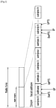
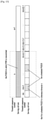
- FIG.1 is a schematic diagram illustrating a frame structure in an LTE TDD system. Each radio frame is 10ms, and is subdivided uniformly into two half-frames of 5ms.
- Each half-frame includes 8 time slots of 0.5ms and 3 special fields of 1ms, i.e. downlink pilot time slot (DwPTS), guard period (GP) and uplink pilot time slot (UpPTS).
- DwPTS downlink pilot time slot
- GP guard period
- UpPTS uplink pilot time slot
- Each subframe is composed of two consecutive time slots. According to the frame structure as shown in FIG.1 , in every 10ms, there are 10 subframes shared by uplink transmission and downlink transmission. Each subframe may be assigned for uplink transmission or downlink transmission.
- a subframe assigned for uplink transmission is referred to as an uplink subframe
- a subframe assigned for downlink transmission is referred to as a downlink subframe.
- TDD systems support 7 types of uplink/downlink (UL/DL) configurations as shown in Table 1, where D stands for downlink subframe, U stands for uplink subframe, S stands for special subframes in the 3 special fields.
- Table 1 LTE TDD UL/DL configuration Configuration serial number Switch-point periodicity Subframe index 0 1 2 3 4 5 6 7 8 9 0 5 ms D S U U U D S U U U 1 5 ms D S U U D D S U U D 2 5 ms D S U D D D S U D D D 3 10 ms D S U U U D D D D D D 4 10 ms D S U U D D D D D D D 5 10 ms D S U D D D D D D D D D D 6 10 ms D S U U U U U D S U U U D S U U U D S U U D
- Downlink data is transmitted through Physical Downlink Shared Channels (PDSCH).
- Hybrid Automatic Retransmission Request-acknowledgement may be transmitted through Physical Uplink Shared Channels (PUSCH) or Physical Uplink Control Channels (PUCCH).
- Uplink data is transmitted through Physical Uplink Shared Channels (PUSCH).
- CC component carriers
- CA carrier aggregation
- Each CC is also referred to as a serving cell.
- the aggregated carriers constitute downlink and uplink links in the communication system, therefore larger transmission rates can be achieved.
- Pcell primary cell
- Scell secondary cells
- PUSCH may be transmitted in any uplink CC
- PUCCH may be transmitted in the Pcell or in a specified uplink Scell.
- P CMAX,c ( i ) is the maximum transmitting power configured for the UE in a serving cell c;
- h n CQI n HARQ n SR n HARQ + n SR + n CQI ⁇ 1 3 .
- P CMAX,c ( i ) is the maximum transmitting power configured for the UE in subframe i in a serving cell c;
- A-CSI Aperiodic CSI
- BPRE O CQI / N RE
- ⁇ offset PUSCH ⁇ offset CQI .
- K r is the number of bits of the r'th CB
- N RE is the total number of resource elements (RE) in a PUSCH.
- a UE may report in a power headroom report (PHR) the power headroom that is left under specific scheduling scheme.
- PHR power headroom report
- the UE may determine whether to report only the PHR of type 1 or report both the PHR of type 1 and the PHR of type 2 according to configurations of the UE as to whether the UE is allowed to transmit a PUSCH and a PUCCH within the same subframe.
- the UE may determine to simultaneously report the PHR of type 1 and the PHR of type 2 to a serving cell that receives reported PUCCH; if the UE is configured not to transmit a PUSCH and a PUCCH within the same subframe, the UE may determine to report only the PHR of type 1 to the serving cell that receives reported PUCCH.
- the following are the methods of calculating the PHR of type 1 and the PHR of type 2.
- definitions of M PUSCH,c ( i ), P O_PUSCH,c ( j ), ⁇ c ( j ), PL c , ⁇ TF, c ( i ) and ⁇ c ( i ) can be found in 3rd Generation Partnership Project (3GPP) 36.213 v10.9.0 Section 5.1.1.1.
- P ⁇ CMAX, c ( i ) is the maximum transmitting power of PUSCH calculated when it is assumed that the UE only transmits PUSCH in the subframe i of the serving cell c.
- definitions of M PUSCH,c ( i ), P O_PUSCH,c ( j ), ⁇ c ( j ), PL c , ⁇ TF, c ( i ) and ⁇ c ( i ) can be found in 3GPP 36.213 v10.9.0 Section 5.1.1.1
- definitions of P O_PUCCH , PL c , h ( n CQI , n HARQ , n SR ) , ⁇ F_PUCCH ( F ), ⁇ TxD ( F' ) and g ( i ) can be found in 3GPP 36.213 v10.9.0 Section 5.1.2.1.
- definitions of M PUSCH,c ( i ), P O - _PUSCH,c ( j ), ⁇ c ( j ), PL c , ⁇ TF, c ( i ) and ⁇ c ( i ) can be found in 3GPP 36.213 v10.9.0 Section 5.1.1.1
- definitions of P O_PUSCH , PL c , and g ( i ) can be found in 3GPP 36.213 v10.9.0 Section 5.1.2.1.
- definitions of P O_PUSCH,c (1), ⁇ c (1), PL c and ⁇ c ( i ) can be found in 3GPP 36.213 v10.9.0 Section 5.1.1.1, and definitions of P O _PUCCH , PL c , h ( n CQI , n HARQ , n SR ), ⁇ F_PUCCH ( F ), and g ( i ) can be found in 3GPP 36.213 v10.9.0 Section 5.1.2.1.
- definitions of P O_PUSCH,c (1), ⁇ c (1), PL c and ⁇ c ( i ) can be found in 3GPP 36.213 v10.9.0 Section 5.1.1.1, and definitions of P O_PUCCH , PL c , and g ( i ) can be found in 3GPP 36.213 v10.9.0 Section 5.1.2.1.
- the eNB may determine the time of transmitting the PHR by configuring two timers and downlink path loss change (dl-PathlossChange) via higher layer signaling.
- the two timers include a periodic PHR timer (PeriodicPHR-Timer) and a prohibit PHR timer (ProhibitPHR-Timer).
- the following codes are the two timers and the dl-PathlossChange configured via higher layer signaling. Configuration of the PeriodicPHR-Timer and the ProhibitPHR-Timer is in unit of subframe of 1ms.
- PHR is to be transmitted when the UE has PUSCH resources for initial transmission data and allocated PUSCH resources can bear PHR MAC control element and subheader.
- extended PHR is configured, a CA system is always configured with extended PHR, and the UE has to report the PHR of all of active serving cells.
- a PHR is generated for each active serving cell, and PHRs of all of active serving cells are transmitted on PUSCH resources of one serving cell.
- extended PHR is not configured, i.e., in a non-CA system, UE has to report the PHR of a serving cell.
- the UE may start or re-start the PeriodicPHR-Timer and the ProhibitPHR-Timer, and cancel all PHR trigger.
- the present application provides a PHR method to enable a UE to report PHR
- the present application also provides a PHR apparatus to implement the method of a UE reports PHR
- the present application provides the following technical schemes.
- a PHR method may include:
- a PHR apparatus comprising: a determining unit, a calculating unit and a transmitting unit,
- the method and apparatus of embodiments of the present disclosure enables a UE to proactively determine the PHR reporting manner, calculate PHR and report the PHR, thus implements PHR reporting process at the UE.
- Various embodiments of the present disclosure provide an improved system performance.
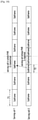
- various embodiments provide a PHR method. As shown in FIG. 2 , the method may include the following procedures.
- a UE determines a PHR reporting manner according to a structure of an uplink subframe in an active serving cell.
- step 202 the UE calculates PHR according to the PHR reporting manner, and transmits the PHR to a base station.
- This embodiment introduces a configuration method and a usage method of a PeriodicPHR-Timer and a ProhibitPHR-Timer of PHR There are the following situations.
- FIG. 3 is a schematic diagram illustrating subframe length in different time periods in a serving cell of a UE in accordance with embodiment one of the present disclosure.
- subframes in some time periods have a length of T1 ms, (e.g., T1 may be 1ms); subframes in some time periods have a length of T2 ms, (e.g., T2 may be 0.5ms).
- FIG. 4 is a schematic diagram illustrating subframe length in different frequency bands within the same time period in a serving cell of a UE in accordance with embodiment one of the present disclosure.
- subframes in some frequency bands have a length of T1 ms, (e.g., T1 may be 1ms); subframes in some frequency bands have a length of T2 ms, (e.g., T2 may be 0.5ms).
- a UE is configured with a plurality of serving cells, i.e., the UE is configured with a plurality of carriers.
- Subframes may have different lengths in different serving cells within the same time period, and the subframe length may be configured by higher layer signaling or pre-defined in a protocol or indicated by physical layer signaling.
- FIG. 5 is a schematic diagram illustrating subframe length in a plurality of serving cells of a UE within the same time period in accordance with embodiment one of the present disclosure. As shown in FIG.
- subframes in some serving cells have a length of T1 ms, (e.g., T1 may be 1ms); subframes in some serving cells have a length of T2 ms, (e.g., T2 may be 0.5ms).
- the UE may use the following method to determine configurations of the PeriodicPHR-Timer and the ProhibitPHR-Timer in PHR, and determine the time of reporting the PHR according to the PeriodicPHR-Timer and the ProhibitPHR-Timer in PHR
- T is configured by higher layer signaling or pre-defined in a protocol, and is referred to as reference time unit.
- T may be configured by higher layer signaling or defined by a protocol as 1ms, after the value of T is determined, the PeriodicPHR-Timer and the ProhibitPHR-Timer may be determined according to configurations as shown below.
- the UE may identify the PeriodicPHR-Timer and the ProhibitPHR-Timer, and determine the time of reporting the PHR according to the two timers.
- T is taken as the unit for numbering all of subframes.
- T is counted by milli-seconds, e.g., the value of T may be 0.5 ms, all of subframes are numbered and the serial number of a subframe is t, t is a natural number.
- the state values of the PeriodicPHR-Timer and the ProhibitPHR-Timer are calculated according to the serial number t of the subframes.
- FIG. 6 is a schematic diagram illustrating example one of PeriodicPHR-Timer and ProhibitPHR-Timer in PHR determined by a UE in accordance with embodiment one of the present disclosure.
- FIG. 7 is a schematic diagram illustrating example two of PeriodicPHR-Timer and ProhibitPHR-Timer in PHR determined by a UE in accordance with embodiment one of the present disclosure.
- another method of determining PeriodicPHR-Timer and ProhibitPHR-Timer includes activating PHR in each of different serving cells or different serving cell sets configured for the UE using an individual PeriodicPHR-Timer and/or ProhibitPHR-Timer.
- Activating PHR using an individual PeriodicPHR-Timer and/or ProhibitPHR-Timer refers to each of different serving cells or different serving cell sets configured for the UE uses the time unit and value of an individual PeriodicPHR-Timer and/or ProhibitPHR-Timer, and PHR of each of different serving cells or PHRs of each of different serving cell sets configured for the UE are activated by respective PeriodicPHR-Timer and/or ProhibitPHR-Timer and reported separately.
- the UE determines the time unit and the value of the PeriodicPHR-Timer and/or ProhibitPHR-Timer corresponding to each serving cell configured for the UE from received higher layer signaling.
- a UE is configured with 3 serving cells, i.e., serving cell 1, serving cell 2 and serving cell 3, and is configured with 2 pairs of PeriodicPHR-Timer and ProhibitPHR-Timer for PHR report, one is PeriodicPHR-Timer-1 and ProhibitPHR-Timer-1, the other is PeriodicPHR-Timer-2 and ProhibitPHR-Timer-2.
- Serving cell 1 and serving cell 2 form a serving cell set whose PHR is activated by PeriodicPHR-Timer-1 and ProhibitPHR-Timer-1 before the PHR of serving cell 1 and PHR of serving cell 2 are reported together.
- PHR of serving cell 3 is activated by PeriodicPHR-Timer-2 and ProhibitPHR-Timer-2 and then reported.
- the method can use a simple processing manner given that different serving cells have different timeslot lengths.
- different serving cells may have very different path losses. Some serving cells may have small changes in path loss, e.g., serving cells operating at low frequency bands may have small changes in path loss. Some other serving cells may have great changes in path loss, e.g., serving cells operating at high frequency bands may have great changes in path loss.
- the PHR report may consume too much physical uplink resources.
- the method of activating PHR using individual PeriodicPHR-Timer and ProhibitPHR-Timer can report only the PHR of serving cells operating at high frequency bands, thus can avoid the consumption of too much physical resources by PHR report.
- subframes of at least one active serving cell When the UE is configured with at least two serving cells, and at least two of the serving cells are activated, subframes of at least one active serving cell have different subframe lengths in different time periods, as shown in FIG. 3 . In another example, when the UE is configured with at least two serving cells, and at least two of the serving cells are activated, subframes of at least one active serving cell have different subframe lengths in different frequency bands within the same time period, as shown in FIG. 4 .
- the UE may determine the subframe length according to the following methods.
- parameters for power control may be different.
- the length of a subframe for transmitting regular service may be 1ms, and the code error rate requirement may be 1%; and the length of a subframe for transmitting high-reliable low-delay service may be 0.25, and the code error rate requirement may be 10e-5.
- the UE needs to report PHR
- two types of services may have different power control parameters, and two types of PHR may be reported, referred to as first type PHR and second type PHR That is because each PUSCH transmission may have corresponding type of PHR reported when different PUSCH transmissions adopt different power control parameters.
- type-1 services are regular services
- type-2 services are services requiring low delay and high reliability.
- waveforms for PUSCH transmission e.g., a type of waveform for PUSCH transmission is cyclic prefix-OFDM (CP-OFDM), another type of waveform for PUSCH transmission is single carrier-OFDM (SC-OFDM), and the two types of waveforms also need to report respective PHRs.
- CP-OFDM cyclic prefix-OFDM
- SC-OFDM single carrier-OFDM
- sub-carrier spaces for PUSCH transmission there are different sub-carrier spaces for PUSCH transmission, e.g., a type of sub-carrier space for PUSCH transmission is 15kHz, another type of sub-carrier space for PUSCH transmission is 60kHz, and the two types of sub-carrier spaces also need to report respective PHRs.
- beams for PUSCH transmission may be in different directions, and respective PHRs of the beams may be reported.
- a UE may identify the number of individual PHRs to be reported and characteristics of the PHRs using received configurations from higher layer signaling or physical signaling.
- Characteristics of each PHR include factors of PUSCH transmission for calculating the PHR, including waveform, sub-carrier space, service, beam, etc.
- the method may be extended to be applied to situations where more than two PHRs are reported, and the reported PHRs have at least one characteristic, e.g., waveform, sub-carrier space, service, beam, different from each other.
- some serving cells may have the same subframe length in different time periods and different frequency bands, and only one type of service is transmitted.
- a set of power control parameters are defined. For example, only one type of PHR is reported to a serving cell which only transmits regular services or only transmits high reliability low-delay services.
- the UE may determine whether to report one type of PHR or two types of PHR for each serving cell configured for the UE.
- the two types of PHR are reported in a time division multiplexing manner, and for each serving cell, only one of the first type PHR and the second type PHR is reported each time.
- the UE may determine whether to report the first type PHR or the second type PHR according to the following manners.
- a UE may identify which subframes are used by the UE for reporting the first type PHR and which subframes are used for reporting the second type PHR, thus the UE and the base station may not mistake the type of reported PHR
- the UE may report a type of PHR corresponding to the subframe as configured by higher layer signaling.
- This method requires the subframes in which the UE transmits different services in the serving cell are also configured by higher layer signaling. Subframes configured for transmitting one type of service cannot be changed dynamically to be subframes for transmitting another type of service, and this may affect timely transmission of high-reliability low-delay services.
- the UE may determine whether to report the first type PHR or the second type PHR in a subframe according to content transmitted in the subframe in a specific serving cell. Specifically, when the subframe transmits PUSCH of category-1 service only, the UE may report the first-type PHR; when the subframe transmits PUSCH of category-2 service only, the UE may report the second type PHR.
- the higher layer signaling configures which subframes are used for reporting the first type PHR by the UE and which subframes are used for reporting the second type PHR
- PHR may be reported according to a default type of PHR determined according to a protocol, e.g., the second type PHR is reported in such situation.
- This method may result in mistaking the type of PHR
- a base station schedules category-1 service which means the UE should report the first type PHR, but the UE does not receive scheduling signaling from the serving cell, the UE may report the second type PHR according to rules, thus the UE and the base station may mistake the type of the PHR reported.
- the UE may distinguish the category-1 service and the category-2 service by different DCI formats or by a bit indicator in DCI or by an RNTI for scrambling the DCI.
- the UE may determine whether to report the first type PHR or the second type PHR in a subframe according to scheduling information of the subframe in a specific serving cell. Specifically, when only PUSCH of category-1 service is transmitted in the subframe, the UE may report the first type PHR. When only PUSCH of category-2 service transmitted in the subframe, the UE may report the second type PHR.
- the type of PHR to be reported by the UE may be determined according to higher layer signaling which configures which subframes are for reporting the first type PHR and which subframes are for reporting the second type PHR
- the type of PHR to be reported may be determined according to a default type of PHR defined in a protocol, e.g., in the above situation, a protocol may define the second type PHR is reported because the category-2 service has higher requirements for reliability and low delay, thus the second type PHR may have priority to be reported.
- a type indicator indicating the type of reported PHR may be added to MAC signaling for reporting the PHR That is, the UE may not only report the PHR, but also specify the type of the PHR
- the type indicator may be a one-bit indicator indicating the PHR type. As such, the UE and the base station will not mistake the type of the reported PHR
- the two types of PHR are reported simultaneously. There are the following manners of simultaneously reporting the first type PHR and the second type PHR
- the calculations may be performed for the following situations.
- the P CMAX, c ,1 ( i ) is the maximum transmitting power in subframe i in the serving cell c of the UE when it is assumed the serving cell c only transmits PUSCH of category-1 service; and all the other parameters are power control parameters of the PUSCH for transmission of the category-1 service.
- M PUSCH, c ,1, ( i ) is the number of physical resource blocks (PRBs) occupied by the PUSCH.
- P 0 _ PUSCH , c ,1 ( j ) is a power offset configured by higher layer signaling.
- ⁇ c, 1 ( j ) is for controlling path loss compensating rate.
- SPS Semi-persistent scheduling
- f c ,1 ( i ) is an accumulative sum of close-loop power control.
- BPRE O CQI / N RE
- ⁇ offset PUSCH ⁇ offset CQI .
- K r is the number of bits of the r'th CB
- N RE is the total number of resource elements (RE) in a PUSCH.
- the P ⁇ CMAX, c ,2 ( i ) is the maximum transmitting power in subframe i in the serving cell c of the UE when it is assumed the serving cell c does not transmit PUSCH of any service. All of the other parameters are power control parameters of the PUSCH for transmission of the category-2 service.
- P 0_PUSCH , c ,2 (1) is a power offset configured by higher layer signaling;
- PL C ,2 is path loss;
- ⁇ c ,2 (1) is for controlling path loss compensating rate;
- f c ,2 ( i ) is an accumulative sum of close-loop power control.
- PH c,2 ( i ) is a virtual PHR
- the P CMAX, c ,2 ( i ) is the maximum transmitting power in subframe i in the serving cell c of the UE when it is assumed the serving cell c only transmits PUSCH of category-2 service; M PUSCH, c ,2, ( i ) is the number of PRBs occupied by the PUSCH.
- P 0_PUSCH,c, 2 ( j ) is a power offset configured by higher layer signaling.
- PL C ,2 is path loss.
- ⁇ c ,2 ( j ) is for controlling path loss compensating rate.
- f c ,2 ( i ) is an accumulative sum of close-loop power control; ⁇ TF, c,2 ( i ) is a parameter in connection with a MCS of uplink transmission.
- PH c,2 ( i ) is a virtual PHR
- All of the other parameters are power control parameters of the PUSCH for transmission of the category-2 service.
- the P ⁇ CMAX, c ,1 ( i ) is the maximum transmitting power in subframe i in the serving cell c of the UE when it is assumed the serving cell c does not transmit PUSCH of any service. and all the other parameters are power control parameters of the PUSCH for transmission of the category-1 service.
- P 0 _ PUSCH,c, 1 (1) is a power offset configured by higher layer signaling.
- PL C ,1 is path loss.
- ⁇ c ,1 (1) is for controlling path loss compensating rate;
- f c ,1 ( i ) is an accumulative sum of close-loop power control.
- PH c ,1 ( i ) is a virtual PHR
- the P ⁇ CMAX,c,1 ( i ) is the maximum transmitting power in subframe i in the serving cell c of the UE when it is assumed the serving cell c does not transmit PUSCH of any service. All of the other parameters are power control parameters of the PUSCH for transmission of the category-1 service.
- P 0 _ PUSCH,c, 1 (1) is a power offset configured by higher layer signaling.
- PL C ,1 is path loss.
- ⁇ c ,1 (1) is for controlling path loss compensating rate.
- f c ,1 ( i ) is an accumulative sum of close-loop power control.
- PH c,1 ( i ) is a pre-set virtual PHR
- the P ⁇ CMAX,c,2 ( i ) is the maximum transmitting power in subframe i in the serving cell c of the UE when it is assumed the serving cell c does not transmit PUSCH of any service. All of the other parameters are power control parameters of the PUSCH for transmission of the category-2 service.
- P 0 _ PUSCH,c, 2 ( j ) is a power offset configured by higher layer signaling.
- PL C ,2 is path loss;
- ⁇ c ,2 ( j ) is for controlling path loss compensating rate.
- f c ,2 ( i ) is an accumulative sum of close-loop power control. Since category-2 service is not transmitted in the serving cell c, PH c,2 ( i ) is a virtual PHR
- the P CMAX, c ,1 ( i ) is the maximum transmitting power in subframe i in the serving cell c of the UE when it is assumed the serving cell c only transmits PUSCH of category-1 service. All of the other parameters are power control parameters of the PUSCH for transmission of the category-1 service.
- M PUSCH, c ,1, ( i ) is the number of physical resource blocks (PRBs) occupied by the PUSCH.
- P 0_PUSCH , c ,1 ( j ) is a power offset configured by higher layer signaling.
- PL C, 1 is path loss.
- ⁇ c, 1 ( j ) is for controlling path loss compensating rate.
- f c, 1 ( i) is an accumulative sum of close-loop power control.
- ⁇ TF , c ,1 ( i ) is a parameter in connection with a MSC of uplink transmission
- PH c,1 ( i ) is a preset virtual PHR
- the P CMAX, c ,2 ( i ) is the maximum transmitting power in subframe i in the serving cell c of the UE when it is assumed the serving cell c only transmits PUSCH of category-2 service. All of the other parameters are power control parameters of the PUSCH for transmission of the category-2 service.
- M PUSCH, c ,2, ( i ) is the number of PRBs occupied by the PUSCH.
- P 0 _ PUSCH , c ,2 ( j ) is a power offset configured by higher layer signaling.
- PL C ,2 is path loss.
- ⁇ c ,2 ( j ) is for controlling path loss compensating rate.
- f c ,2 ( i ) is an accumulative sum of close-loop power control.
- ⁇ TF , c ,2 ( i ) is a parameter in connection with a MSC of uplink transmission
- PH c ,2 ( i ) is a preset virtual PHR
- the two types of PHR are reported simultaneously. There are the following manners of simultaneously reporting the first type PHR and the second type PHR
- FIG. 8 is a schematic diagram illustrating a subframe length one of a plurality of serving cells of a UE of method three in accordance with embodiment two of the present disclosure.
- PHR of serving cell 2 is transmitted in PUSCH of serving cell 1
- the subframe of serving cell 1 for transmitting the PHR has the same subframe length with the subframe of serving cell 2 for calculating the PHR
- FIG. 9 when a serving cell for which PHR is selected to be transmitted by the UE has the same subframe length with that of a serving cell to which the PHR is reported, the situation is as shown in FIG. 9.
- FIG. 9 is a schematic diagram illustrating a subframe length one of a plurality of serving cells of a UE of method three in accordance with embodiment two of the present disclosure.
- FIG. 9 is a schematic diagram illustrating a subframe length two of a plurality of serving cells of a UE of method three in accordance with embodiment two of the present disclosure.
- PHR of serving cell 1 is transmitted in PUSCH of serving cell 2, and the subframe of serving cell 2 for transmitting the PHR has the same subframe length with the subframe of serving cell 1 for calculating the PHR
- the UE since the serving cell having the longer subframe length has a longer time interval from receiving an instruction of scheduling PUSCH to sending the PUSCH than the serving cell having the shorter subframe length, the UE has enough time after receiving the scheduling instruction to calculate the PHR of the serving cell having the shorter subframe length and then transmits the PHR, the UE may use the following method to report the two types of PHR
- the P CMAX, c ,1 ( i ) is the maximum transmitting power in subframe i in the serving cell c of the UE when it is assumed the serving cell c only transmits PUSCH of category-1 service. All of the other parameters are power control parameters of the PUSCH for transmission of the category-1 service.
- M PUSCH, c ,1, ( i ) is the number of PRBs occupied by the PUSCH.
- P 0_PUSCH , c ,1 ( j ) is a power offset configured by higher layer signaling.
- PL C ,1 is path loss.
- ⁇ c ,1 ( j ) is for controlling path loss compensating rate.
- f c ,1 ( i ) is an accumulative sum of close-loop power control.
- ⁇ TF,c, 1 ( i ) is a parameter in connection with a MSC of uplink transmission
- PH c,1 ( i ) is a preset virtual PHR
- the P ⁇ CMAX,c,2 ( i ) is the maximum transmitting power in subframe i in the serving cell c of the UE when it is assumed the serving cell c does not transmit PUSCH of any service. All of the other parameters are power control parameters of the PUSCH for transmission of the category-2 service.
- PH c,2 ( i ) is a virtual PHR
- P 0 _ PUSCH , c ,2 (1) is a power offset configured by higher layer signaling.
- PL C ,2 is path loss.
- ⁇ c ,2 (1) is for controlling path loss compensating rate;
- f c ,2 ( i ) is an accumulative sum of close-loop power control.
- PH c,2 ( i ) is a pre-set virtual PHR
- the P CMAX, c ,2 ( i ) is the maximum transmitting power in subframe i in the serving cell c of the UE when it is assumed the serving cell c only transmits PUSCH of category-2 service. All of the other parameters are power control parameters of the PUSCH for transmission of the category-2 service.
- M PUSCH, c ,2, ( i ) is the number of PRBs occupied by the PUSCH.
- P 0 _ PUSCH , c ,2 ( j ) is a power offset configured by higher layer signaling.
- PL C ,2 is path loss.
- ⁇ c ,2 ( j ) is for controlling path loss compensating rate.
- f c ,2 ( i ) is an accumulative sum of close-loop power control.
- ⁇ TF , c ,2 ( i ) is a parameter in connection with a MCS of uplink transmission.
- PH c,2 ( i ) is a virtual PHR
- the P ⁇ CMAX, c ,1 ( i ) is the maximum transmitting power in subframe i in the serving cell c of the UE when it is assumed the serving cell c does not transmit PUSCH of any service. All of the other parameters are power control parameters of the PUSCH for transmission of the category-1 service.
- PH c,1 ( i ) is a virtual PHR
- P 0 _ PUSCH,c, 1 (1) is a power offset configured by higher layer signaling.
- PL C ,1 is path loss.
- ⁇ c ,1 (1) is for controlling path loss compensating rate;
- f c ,1 ( i ) is an accumulative sum of close-loop power control.
- PH c,1 ( i ) is a pre-set virtual PHR
- the P ⁇ CMAX,c,2 ( i ) is the maximum transmitting power in subframe i in the serving cell c of the UE when it is assumed the serving cell c does not transmit PUSCH of any service. All of the other parameters are power control parameters of the PUSCH for transmission of the category-2 service.
- PH c,2 ( i ) is a virtual PHR
- P 0 _ PUSCH , c ,2 ( j ) is a power offset configured by higher layer signaling.
- PL C ,2 is path loss.
- ⁇ c ,2 ( j ) is for controlling path loss compensating rate.
- f c ,2 ( i ) is an accumulative sum of close-loop power control; and
- PH c,2 ( i ) is a virtual PHR
- the P CMAX, c ,1 ( i ) is the maximum transmitting power in subframe i in the serving cell c of the UE when it is assumed the serving cell c only transmits PUSCH of category-1 service. All of the other parameters are power control parameters of the PUSCH for transmission of the category-1 service.
- M PUSCH, c ,1 ,( i ) is the number of PRBs occupied by the PUSCH.
- P 0-_PUSCH , c ,1 ( j ) is a power offset configured by higher layer signaling.
- PL C ,1 is path loss.
- ⁇ c ,1 ( j ) is for controlling path loss compensating rate.
- f c ,1 ( i ) is an accumulative sum of close-loop power control.
- ⁇ TF,c ,1 ( i ) is a parameter in connection with a MSC of uplink transmission
- PH c,1 ( i ) is a preset virtual PHR
- the P CMAX, c ,2 ( i ) is the maximum transmitting power in subframe i in the serving cell c of the UE when it is assumed the serving cell c only transmits PUSCH of category-2 service. All of the other parameters are power control parameters of the PUSCH for transmission of the category-2 service.
- M PUSCH, c ,2, ( i ) is the number of PRBs occupied by the PUSCH.
- P 0 _ PUSCH , c ,2 ( j ) is a power offset configured by higher layer signaling.
- PL C ,2 is path loss.
- ⁇ c ,2 ( j ) is for controlling path loss compensating rate.
- f c ,2 ( i ) is an accumulative sum of close-loop power control.
- ⁇ TF , c ,2 ( i ) is a parameter in connection with a MSC of uplink transmission
- PH c,2 ( i ) is a preset virtual PHR
- FIG. 10 is a schematic diagram illustrating a subframe length three of a plurality of serving cells of a UE of method three in accordance with embodiment two of the present disclosure.
- the PHR of serving cell 2 is transmitted in PUSCH of serving cell 1, and the subframe of serving cell 1 for transmitting the PHR has a larger subframe length than the subframe of serving cell 1 for calculating the PHR
- the UE since the serving cell having the longer subframe length has a longer time interval from receiving an instruction of scheduling PUSCH to sending the PUSCH than the serving cell having the shorter subframe length, the UE may have not enough time after receiving the scheduling instruction from the serving cell having the shorter subframe length to calculate the PHR according to the scheduling condition of the shorter subframe and then transmits the PHR in the serving cell having the longer subframe length because operations such as coding or the like for the serving cell having longer subframes are more time-consuming.
- the above method may be used, i.e., the method of calculating the two types of PHR when the serving cell for which PHR is selected to be transmitted by the UE has the same subframe length with that of a serving cell to which the PHR is reported. If the UE does not have enough time to calculate PHR according to scheduling condition of the shorter subframe after receiving a scheduling command from the serving cell having the shorter subframe and transmits the PHR in the serving cell having the longer subframe, the UE may report the two types of PHR according to the following method.
- P ⁇ CMAX, c ,1 ( i ) is the maximum transmission power on subframe i in the serving cell c of the UE when it is assumed the serving cell c does not transmit PUSCH of any service, and P 0 _ PUSCH , c ,1 (1) is a power offset configured by higher layer signaling.
- PL C ,1 is path loss.
- ⁇ c ,1 (1) is for controlling path loss compensating rate;
- f c,1 ( i ) is an accumulative sum of close-loop power control.
- PH c,1 ( i ) is a pre-set virtual PHR
- P ⁇ CMAX,c,2 ( i ) is the maximum transmission power on subframe i in the serving cell c of the UE when it is assumed the serving cell c does not transmit PUSCH of any service, and P 0 _ PUSCH , c ,2 ( j ) is a power offset configured by higher layer signaling.
- PL C ,2 is path loss.
- ⁇ c ,2 ( j ) is for controlling path loss compensating rate.
- f c ,2 ( i ) is an accumulative sum of close-loop power control; and PH c,2 ( i ) is a virtual PHR
- This embodiment provides a method of transmitting PHR for plural serving cells configured for a UE.
- at least two of the serving cells have different timeslot lengths, or different frequency bands or different time have different timeslot lengths within a serving cell.
- a UE is configured with two serving cells, among which serving cell 1 has a timeslot length T and serving cell 2 has a timeslot length of T/m, T is the length of the reference timeslot for reporting PHR
- the UE may calculate PHR according to information of PUSCH in the serving cell within timeslot n when the UE is to report PHR in reference timeslot n.
- the UE When the serving cell has a shorter timeslot length than that of the reference timeslot, i.e., when reporting PHR in reference timeslot n, the UE reports PHR in plural timeslots of the serving cell.
- the serving cell may have m timeslots, including timeslots m ⁇ n, m ⁇ n+1, «, m ⁇ n+m-1, within reference timeslot n.
- the m timeslots may have different PUSCH scheduling conditions, and the UE may select PUSCH transmission information of one of the timeslots for the PHR.
- the following are some of methods of selecting PUSCH transmission information of one of the timeslots for calculating PHR, in which the value of m is obtained by the UE through an explicit manner or an inexplicit manner.
- the selected timeslot for PHR calculation is the first timeslot in which PUSCH is scheduled in the timeslots of the serving cell within the reference timeslot, and the UE has enough time to calculate the PHR using information of the scheduled PUSCH after receiving the scheduling command.
- virtual PHR may be used.
- the virtual PHR refers to PHR calculated for no PUSCH transmission.
- the virtual PHR may be used.
- a UE is configured with two serving cells, in which serving cell one has the same timeslot length T with the reference timeslot and serving cell two has a timeslot length of T/m.
- the serving cell two has a total of m timeslots, i.e., timeslots m ⁇ n, m ⁇ n+1, «, m ⁇ n+m-1, in reference timeslot n.
- the first scheduled PUSCH is in timeslot m ⁇ n+1.
- the UE When PHR is transmitted in PUSCH in timeslot m ⁇ n+1 of serving cell two, the UE has enough time to calculate the PHR according to information of the PUSCH scheduled in the timeslot m ⁇ n+1, thus the UE calculates the PHR according to information of the PUSCH scheduled in the timeslot m ⁇ n+1, as shown in FIG. 12 .
- the UE may not have enough time to calculate PHR according to information of the PUSCH scheduled in timeslot m ⁇ n+1 of serving cell two because the PUSCH for transmitting the PHR starts early, thus the PHR of the serving cell two is the virtual PHR calculated according to there is no PUSCH transmission in serving cell two, as shown in FIG. 13 .
- the selected timeslot for calculating PHR is the last timeslot in which PUSCH is scheduled among timeslots of the serving cell that fall within the reference timeslot and which satisfies that the UE has enough time to calculate the PHR according to information of the scheduled PUSCH after receiving the scheduling command.
- virtual PHR may be used when the UE does not have enough time to calculate the PHR using information of the scheduled PUSCH after receiving the scheduling command.
- the virtual PHR refers to PHR calculated for no PUSCH transmission.
- the virtual PHR may be used when there is no PUSCH transmission in all of the timeslots in the reference timeslots for reporting PHR.
- a UE is configured with two serving cells, in which serving cell one has the same timeslot length T with the reference timeslot and serving cell two has a timeslot length of T/m.
- the serving cell two has timeslots m ⁇ n, m ⁇ n+1, «, m ⁇ n+m-1 that fall within reference timeslot n.
- the first scheduled PUSCH is in timeslot m ⁇ n+1.
- the UE When PHR is transmitted in PUSCH in timeslot m ⁇ n+1 of serving cell two, the UE has enough time to calculate the PHR according to information of the PUSCH scheduled in the timeslot m ⁇ n+1, thus the UE calculates the PHR according to information of the PUSCH scheduled in the timeslot m ⁇ n+1, as shown in FIG. 12 .
- the UE may not have enough time to calculate PHR according to information of the PUSCH scheduled in timeslot m ⁇ n+1 of serving cell two because the PUSCH for transmitting the PHR starts early, thus the PHR of the serving cell two is the virtual PHR calculated according to there is no PUSCH transmission in serving cell two, as shown in FIG. 13 .
- the selected timeslot for calculating PHR is the first timeslot among timeslots of the serving cell that fall within the reference timeslot.
- the UE transmits PUSCH in the first timeslot of the serving cell and the UE has enough time to calculate the PHR using information of the scheduled PUSCH after receiving the scheduling command, the UE calculates the PHR using information of PUSCH transmission in the first timeslot of the serving cell; otherwise, virtual PHR may be used.
- a UE is configured with two serving cells, in which serving cell one has the same timeslot length T with the reference timeslot and serving cell two has a timeslot length of T/m.
- the serving cell two has timeslots m ⁇ n, m ⁇ n+1, «, m ⁇ n+m-1 that fall within reference timeslot n.
- the UE When PUSCH is transmitted in the first timeslot m ⁇ n of serving cell two and the UE transmits PHR in the PUSCH which is transmitted in timeslot m ⁇ n of serving cell two, the UE has enough time to calculate the PHR according to information of the PUSCH scheduled in the timeslot m ⁇ n, thus the UE calculates the PHR according to information of the PUSCH scheduled in the timeslot m ⁇ n.
- the UE may not have enough time to calculate PHR according to information of the PUSCH scheduled in timeslot m ⁇ n of serving cell two, or the UE does not transmit PUSCH in the timeslot m ⁇ n of serving cell two, the PHR of the serving cell two is the virtual PHR calculated according to there is no PUSCH transmission in serving cell two.
- the selected timeslot for calculating PHR is the last timeslot among timeslots of the serving cell that fall within the reference timeslot.
- the UE transmits PUSCH in the last timeslot of the serving cell and the UE has enough time to calculate the PHR using information of the scheduled PUSCH after receiving the scheduling command, the UE calculates the PHR using information of PUSCH transmission in the last timeslot of the serving cell; otherwise, virtual PHR may be used.
- a UE is configured with two serving cells, in which serving cell one has the same timeslot length T with the reference timeslot and serving cell two has a timeslot length of T/m.
- the serving cell two has timeslots m ⁇ n, m ⁇ n+1, «, m ⁇ n+m-1 that fall within reference timeslot n.
- the UE When PUSCH is transmitted in the last timeslot m ⁇ n+m-1 of serving cell two and the UE transmits PHR in the PUSCH which is transmitted in the timeslot m ⁇ n+m-1 of serving cell two, the UE has enough time to calculate the PHR according to information of the PUSCH scheduled in the timeslot m ⁇ n+m-1, thus the UE calculates the PHR according to information of the PUSCH scheduled in the timeslot m ⁇ n+m-1.
- the UE may not have enough time to calculate PHR according to information of the PUSCH scheduled in timeslot m ⁇ n+m-1 of serving cell two, or the UE does not transmit PUSCH in the timeslot m ⁇ n+m-1 of serving cell two, the PHR of the serving cell two is the virtual PHR calculated according to there is no PUSCH transmission in serving cell two.
- the selected timeslot for calculating PHR is a timeslot determined according to an implementation manner among timeslots of the serving cell that fall within the reference timeslot for reporting PHR PUSCHs in different timeslots may schedule different numbers of physical resource blocks (PRBs), thus the number of PRBs assumed by the UE and the base station to be scheduled may be different when calculating the PHR, and the base station and the UE may have different understanding about the remaining power.
- the UE may calculate PHR according to the number of PRBs obtained from configurations received from higher layer signaling or according to a number of PRBs pre-defined in a protocol instead of according to the number of PRBs actually scheduled by the UE.
- the UE and the base station will not have different numbers of PRBs assumed to be scheduled in PHR calculation.
- the base station may calculate the remaining power according to the PHR For example, when the UE schedules 2 PRBs for PUSCH transmission in timeslot 1, and schedules 3 PRBs for PUSCH transmission in timeslot 2, the UE may calculates the PHR by using 1 PRB which is the pre-defined number of scheduled PRBs.
- the PHR of the serving cell is virtual PHR
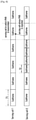
- FIG. 14 is a schematic diagram illustrating modules of PHR apparatus in accordance with embodiments of the present disclosure.
- the apparatus may include: a determining unit, a calculating unit and a transmitting unit.
- the determining unit is for determining a PHR reporting manner according to a structure of an uplink subframe in an active serving cell
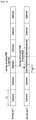
- FIG. 15 is a schematic diagram illustrating an example configuration of a terminal in a wireless communication system according to an exemplary embodiment of the disclosure.
- FIG. 15 illustrates an example of a configuration of the terminal.
- the term "unit” or the term ending with the suffix "-er” or “-or” refer to a unit for processing at least one function or operation and these terms may be implemented by using hardware or software or a combination of hardware and software.
- the terminal includes a communication interface 1510, a storage 1520, and a controller 1530.
- the communication interface 1510 performs functions for transmitting and receiving signals via a radio channel. For example, the communication interface 1510 performs a function of converting between a baseband signal and a bit string according to a physical layer standard of a system. For example, when transmitting data, the communication interface 1510 generates complex symbols by encoding and modulating a transmission bit string. In addition, when receiving data, the communication interface 1510 restores a reception bit string by demodulating and decoding a baseband signal. In addition, the communication interface 1510 up-converts a baseband signal into an RF band signal and then transmit the RF band signal through an antenna, and down-converts an RF band signal received through the antenna into a baseband signal.
- the communication interface 1510 may include a transmission filter, a reception filter, an amplifier, a mixer, an oscillator, a DAC, an ADC, or the like.
- the communication interface 1510 may include a plurality of transmission/reception paths.
- the communication interface 1510 may include at least one antenna array configured by a plurality of antenna elements.
- the communication interface 1510 may be configured by a digital circuitry and an analog circuitry (e.g., radio frequency integrated circuit (RFIC)).
- RFIC radio frequency integrated circuit
- the digital circuitry and analog circuitry may be implemented as one package.
- the communication interface 1510 may include a plurality of RF chain.
- the communication interface 1510 may perform beamforming.
- the wireless communication interface 1510 transmits and receives signals as described above. Accordingly, the communication interface 1510 may be referred to as a transmission interface, a reception interface, a transmission and reception interface, a transmitter, a receiver or a transceiver. In addition, in the following description, transmitting and receiving performed through a radio channel may include processing by the communication interface 1510 as described above.
- the storage 1520 stores data such as a basic program for the operation of the terminal, an application program, setting information, or the like.
- the storage 1510 may be configured by a volatile memory, a nonvolatile memory, or a combination of a volatile memory and a nonvolatile memory.
- the storage 1520 provides stored data in response to a request of the controller 330.
- the controller 1530 controls overall operations of the terminal. For example, the controller 1530 transmits and receives signals through the communication interface 1510. In addition, the controller 1530 records and reads data on and from the storage 1520.
- the controller 1530 may perform functions of a protocol stack which the communication standard requires. To achieve this, the controller 1530 may include at least one processor or microprocessor or may be a part of the processor. In addition, a part of the communication interface 1510 and the controller 1530 may be referred to as a communication processor (CP).
- CP communication processor
- the controller 1530 may determine a PHR reporting manner according to a structure of an uplink subframe in an active serving cell, determine PHR according to the PHR reporting manner, and transmit the PHR to a base station.
- the controller 330 may control the terminal to perform operations according to the exemplary embodiments of the present disclosure.
Landscapes
- Engineering & Computer Science (AREA)
- Computer Networks & Wireless Communication (AREA)
- Signal Processing (AREA)
- Mobile Radio Communication Systems (AREA)
Abstract
Description
- The present application relates to mobile communications, and particularly, to a power headroom report (PHR) method and apparatus.
- To meet the demand for wireless data traffic having increased since deployment of 4th generation (4G) communication systems, efforts have been made to develop an improved 5th generation (5G) or pre-5G communication system. Therefore, the 5G or pre-5G communication system is also called a 'Beyond 4G Network' or a 'Post Long Term Evolution (LTE) System'.
- The 5G communication system is considered to be implemented in higher frequency (mmWave) bands, e.g., 28GHz or 60GHz bands, so as to accomplish higher data rates. To decrease propagation loss of the radio waves and increase the transmission distance, the beamforming, massive multiple-input multiple-output (MIMO), Full Dimensional MIMO (FD-MIMO), array antenna, an analog beam forming, large scale antenna techniques are discussed in 5G communication systems.
- In addition, in 5G communication systems, development for system network improvement is under way based on advanced small cells, cloud Radio Access Networks (RANs), ultra-dense networks, device-to-device (D2D) communication, wireless backhaul, moving network, cooperative communication, Coordinated Multi-Points (CoMP), reception-end interference cancellation and the like.
- In the 5G system, Hybrid frequency shift keying (FSK) and quadrature amplitude modulation (FQAM) and sliding window superposition coding (SWSC) as an advanced coding modulation (ACM), and filter bank multi carrier (FBMC), non-orthogonal multiple access (NOMA), and sparse code multiple access (SCMA) as an advanced access technology have been developed.
- The Long Term Evolution (LTE) systems support two duplexing modes, i.e. Frequency Division Duplexing (FDD) and Time Division Duplexing (TDD). Transmission in an LTE system includes downlink transmission which is from a base station (e.g., eNB) to a user equipment (UE) and uplink transmission which is from a UE to a base station. In a TDD system, uplink transmission and downlink transmission are performed on the same carrier at different time. In an FDD system, uplink transmission and downlink transmission are performed on different carriers.
FIG.1 is a schematic diagram illustrating a frame structure in an LTE TDD system. Each radio frame is 10ms, and is subdivided uniformly into two half-frames of 5ms. Each half-frame includes 8 time slots of 0.5ms and 3 special fields of 1ms, i.e. downlink pilot time slot (DwPTS), guard period (GP) and uplink pilot time slot (UpPTS). Each subframe is composed of two consecutive time slots. According to the frame structure as shown inFIG.1 , in every 10ms, there are 10 subframes shared by uplink transmission and downlink transmission. Each subframe may be assigned for uplink transmission or downlink transmission. A subframe assigned for uplink transmission is referred to as an uplink subframe, and a subframe assigned for downlink transmission is referred to as a downlink subframe. TDD systems support 7 types of uplink/downlink (UL/DL) configurations as shown in Table 1, where D stands for downlink subframe, U stands for uplink subframe, S stands for special subframes in the 3 special fields. Table 1: LTE TDD UL/DL configurationConfiguration serial number Switch-point periodicity Subframe index 0 1 2 3 4 5 6 7 8 9 0 5 ms D S U U U D S U U U 1 5 ms D S U U D D S U U D 2 5 ms D S U D D D S U D D 3 10 ms D S U U U D D D D D 4 10 ms D S U U D D D D D D 5 10 ms D S U D D D D D D D 6 10 ms D S U U U D S U U D - Downlink data is transmitted through Physical Downlink Shared Channels (PDSCH). Hybrid Automatic Retransmission Request-acknowledgement (HARQ-ACK) may be transmitted through Physical Uplink Shared Channels (PUSCH) or Physical Uplink Control Channels (PUCCH). Uplink data is transmitted through Physical Uplink Shared Channels (PUSCH).
- In an LTE system, multiple component carriers (CC) are aggregated to obtain larger working bandwidth, i.e., carrier aggregation (CA). Each CC is also referred to as a serving cell. The aggregated carriers constitute downlink and uplink links in the communication system, therefore larger transmission rates can be achieved. When a UE is configured to be in a CA mode, one of cells is a primary cell (Pcell), and other cells are referred to as secondary cells (Scell). According to LTE, PUSCH may be transmitted in any uplink CC, and PUCCH may be transmitted in the Pcell or in a specified uplink Scell.
- Under current LTE provisions, the transmitting power of a PUCCH in subframe i of a serving cell c is determined according to the below formula:

- Definitions of parameters in the above formula can be found in 3rd Generation Partnership Project (3GPP) 36.213 v10.9.0 Section 5.1.2.1. The following is a brief introduction to the parameters.
- P CMAX,c(i) is the maximum transmitting power configured for the UE in a serving cell c;
- ΔF_PUCCH(F) is a power offset from a reference format (which is PUCCH format 1a in LTE);
- Δ TxD (F') is a parameter related with the PUCCH format and whether transmitter diversity is used;
- PLc is path loss;
- P O_PUCCH is power offset configured by higher layer signaling;
- g(i) is an accumulative sum of closed-loop power control;
- h(nCQI , nHARQ , nSR ) is power offset in connection with PUCCH format, is also related with the number of bits of uplink control information (UCI) to be fed back, nCQI is the number of bits of channel state information (CSI) to be fed back in subframe i, nSR is the number of bits of scheduling request (SR) to be fed back in subframe i, the value of nSR is 0 or 1, and nHARQ is the number of bits of HARQ-ACK that are actually to be fed back in subframe i.
- For example, for
PUCCH format 3, when CSI is to be fed back,
- According to current LTE provisions, the transmitting power of a PUSCH in subframe i of a serving cell c is determined according to the below formula:

- Definitions of parameters in the above formula can be found in 3rd Generation Partnership Project (3GPP) 36.213 v10.9.0 Section 5.1.1.1. The following is a brief introduction to the parameters.
- P CMAX,c(i) is the maximum transmitting power configured for the UE in subframe i in a serving cell c;
- M PUSCH,c(i) is the number of physical resource blocks (PRB) occupied by the PUSCH;
- P O_PUSCH,c(j) is a power offset configured by higher layer signaling;
- PLc is path loss;
- αc (j) is for controlling the path loss compensating rate; j=0 for PUSCH or PUSCH re-transmission in Semi-persistent scheduling (SPS); j=1 for PUSCH or PUSCH re-transmission in dynamic scheduling; j=2 for PUSCH or PUSCH re-transmission in random access response (RAR) scheduling.
- ƒc (i) is an accumulative value of closed-loop power control;
Δ TF,c(i) is a parameter related with modulation and coding scheme (MCS) of uplink transmission. Specifically, when KS equals 1.25,


- In order to provide reference to a base station for scheduling uplink resources, a UE may report in a power headroom report (PHR) the power headroom that is left under specific scheduling scheme. The UE may determine whether to report only the PHR of
type 1 or report both the PHR oftype 1 and the PHR oftype 2 according to configurations of the UE as to whether the UE is allowed to transmit a PUSCH and a PUCCH within the same subframe. That is, if the UE is configured to transmit a PUSCH and a PUCCH within the same subframe, the UE may determine to simultaneously report the PHR oftype 1 and the PHR oftype 2 to a serving cell that receives reported PUCCH; if the UE is configured not to transmit a PUSCH and a PUCCH within the same subframe, the UE may determine to report only the PHR oftype 1 to the serving cell that receives reported PUCCH. The following are the methods of calculating the PHR oftype 1 and the PHR oftype 2. - If the UE transmits a PUSCH without transmitting a PUCCH in a subframe i of serving cell d, the may be calculated according to the following formula:

- Definitions of parameters in the above formula can be found in 3rd Generation Partnership Project (3GPP) 36.213 v10.9.0 Section 5.1.1.1.
- If the UE transmits a PUSCH and a PUCCH both in a subframe i of serving cell c, the type-1 PHR may be calculated according to the following formula:

- In the formula, definitions of M PUSCH,c(i), P O_PUSCH,c(j), αc (j), PLc , ΔTF,c (i) and ƒc (i) can be found in 3rd Generation Partnership Project (3GPP) 36.213 v10.9.0 Section 5.1.1.1.
- P̃ CMAX,c (i) is the maximum transmitting power of PUSCH calculated when it is assumed that the UE only transmits PUSCH in the subframe i of the serving cell c.
- If the UE does not transmit a PUSCH in a subframe i of serving cell c, the type-1 PHR may be calculated according to the following formula:

- Definitions of parameters in the above formula can be found in 3rd Generation Partnership Project (3GPP) 36.213 v10.9.0 Section 5.1.1.1.
- If the UE transmits both a PUSCH and a PUCCH in a subframe i of serving cell c, the type-2 PHR may be calculated according to the following formula:

- In the formula, definitions of M PUSCH,c(i), P O_PUSCH,c(j), αc (j), PLc , ΔTF,c (i) and ƒc (i) can be found in 3GPP 36.213 v10.9.0 Section 5.1.1.1, definitions of P O_PUCCH, PLc , h(nCQI ,nHARQ ,nSR ) , ΔF_PUCCH(F), Δ TxD (F') and g(i) can be found in 3GPP 36.213 v10.9.0 Section 5.1.2.1.
- If the UE transmits a PUSCH without transmitting a PUCCH in a subframe i of serving cell c, the type-2 PHR may be calculated according to the following formula:

- In the formula, definitions of M PUSCH,c(i), P O-_PUSCH,c(j), αc (j), PLc , ΔTF,c (i) and ƒc (i) can be found in 3GPP 36.213 v10.9.0 Section 5.1.1.1, definitions of P O_PUSCH, PLc , and g(i) can be found in 3GPP 36.213 v10.9.0 Section 5.1.2.1.
- If the UE transmits a PUSCH without transmitting a PUCCH in a subframe i of serving cell c, the type-2 PHR may be calculated according to the following formula:

- In the formula, definitions of P O_PUSCH,c(1), αc (1), PLc and ƒc (i) can be found in 3GPP 36.213 v10.9.0 Section 5.1.1.1, and definitions of P O_PUCCH, PLc , h(nCQI ,nHARQ ,nSR ), ΔF_PUCCH(F), and g(i) can be found in 3GPP 36.213 v10.9.0 Section 5.1.2.1.
- If the UE does not transmit a PUSCH nor a PUCCH in a subframe i of serving cell c, the type-2 PHR may be calculated according to the following formula:

- In the formula, definitions of P O_PUSCH,c(1), αc (1), PLc and ƒc (i) can be found in 3GPP 36.213 v10.9.0 Section 5.1.1.1, and definitions of P O_PUCCH, PLc , and g(i) can be found in 3GPP 36.213 v10.9.0 Section 5.1.2.1.
- The eNB may determine the time of transmitting the PHR by configuring two timers and downlink path loss change (dl-PathlossChange) via higher layer signaling. The two timers include a periodic PHR timer (PeriodicPHR-Timer) and a prohibit PHR timer (ProhibitPHR-Timer). The following codes are the two timers and the dl-PathlossChange configured via higher layer signaling. Configuration of the PeriodicPHR-Timer and the ProhibitPHR-Timer is in unit of subframe of 1ms.
   phr-Config CHOICE {
   release NULL,
   setup SEQUENCE {
   periodicPHR-Timer ENUMERATED {sf10, sf20, sf50, sf100, sf200,
                                                           sf500,
                                                           sf1000, infinity},
   prohibitPHR-Timer ENUMERATED {sf0, sf10, sf20, sf50, sf100,
                                                           sf200, sf500,
                                                           sf1000},
   dl-PathlossChange ENUMERATED {dB1, dB3, dB6, infinity}
   } }
   Any one of the following events may trigger the PHR
- 1. the ProhibitPHR-Timer ends or has ended and the change in path loss of any serving cell exceeds a pre-determined range of path loss change;
- 2. the PeriodicPHR-Timer ends;
- 3. functions of PHR is configured or re-configured;
- 4. a serving cell configured with uplink transmission is activated.
- determining, by a UE, a PHR reporting manner according to a structure of an uplink subframe in an active serving cell; and
- calculating, by the UE, PHR according to the PHR reporting manner, and transmitting the PHR to a base station.
- the determining unit is for determining a PHR reporting manner according to a structure of an uplink subframe in an active serving cell;
- the calculating module is for calculating the PHR according to the PHR reporting manner; and
- the transmitting unit is for transmitting the calculated PHR to a base station.
-
FIG. 1 is a schematic diagram illustrating a conventional frame structure in an LTE TDD system. -
FIG. 2 is a flowchart illustrating a PHR method in accordance with embodiments of the present disclosure; -
FIG. 3 is a schematic diagram illustrating subframe lengths in different time periods of a serving cell of a UE in accordance with embodiment one of the present disclosure; -
FIG. 4 is a schematic diagram illustrating subframe lengths in different frequency bands within the same time period of a serving cell of a UE in accordance with embodiment one of the present disclosure; -
FIG. 5 is a schematic diagram illustrating subframe lengths in the same time period of different serving cells of a UE in accordance with embodiment one of the present disclosure; -
FIG. 6 is a schematic diagram illustrating a first example of PeriodicPHR-Timer and ProhibitPHR-Timer determined by a UE in PHR in accordance with embodiment one of the present disclosure; -
FIG. 7 is a schematic diagram illustrating a second example of PeriodicPHR-Timer and ProhibitPHR-Timer determined by a UE in PHR in accordance with embodiment one of the present disclosure; -
FIG. 8 is a schematic diagram illustrating a subframe length one of a plurality of serving cells of a UE of method three in accordance with embodiment two of the present disclosure; -
FIG. 9 is a schematic diagram illustrating a subframe length two of a plurality of serving cells of a UE of method three in accordance with embodiment two of the present disclosure; -
FIG. 10 is a schematic diagram illustrating a subframe length three of a plurality of serving cells of a UE of method three in accordance with embodiment two of the present disclosure; and -
FIG. 11 is a schematic diagram illustrating timeslots with timeslot length one of plural serving cells of a UE in accordance with method three of embodiment three of the present disclosure; -
FIG. 12 is a schematic diagram illustrating timeslots with timeslot length one of plural serving cells of a UE in accordance with method one of embodiment three of the present disclosure; -
FIG. 13 is a schematic diagram illustrating timeslots with timeslot length two of plural serving cells of a UE in accordance with method one of embodiment three of the present disclosure; -
FIG. 14 is a schematic diagram illustrating modules of PHR apparatus in accordance with embodiments of the present disclosure; and -
FIG. 15 is a schematic diagram illustrating an example configuration of a terminal in a wireless communication system according to an exemplary embodiment of the disclosure.
   phr-Config CHOICE {
   release NULL,
   setup SEQUENCE {
   periodicPHR-Timer ENUMERATED {10T, 20T, 50T, 100T,
   200T,500T, 1000T, infinity},
   prohibitPHR-Timer ENUMERATED {0T, 10T, 20T, 50T, 100T,
      200T, 500T, 1000T },
             }
- 1) The UE may determine the subframe length according to received higher layer signaling.
- 2) The UE may determine the subframe length according to received public physical layer signaling.
- 3) The UE may determine the subframe length according to received UE-specific physical layer signaling, e.g., the length of a subframe which transmits a PUSCH may be identified using uplink (UL) downlink control information (DCI) which schedules the PUSCH.
the first type PHR may be calculated as:


the second type PHR may be calculated as:

the first type PHR may be calculated as:
the first type PHR may be calculated as:


the first type PHR may be calculated as:


the first type PHR may be calculated as:
the first type PHR may be calculated as:


the first type PHR may be calculated as:
- the calculating module is for calculating the PHR according to the PHR reporting manner; and
- the transmitting unit is for transmitting the calculated PHR to a base station.
-
Clause 1. A method for operating a terminal in a wireless communication system, the method comprising: determining a power headroom report (PHR) reporting manner according to a structure of an uplink subframe in an active serving cell; determining PHR according to the PHR reporting manner; and transmitting the PHR to a base station. -
Clause 2. The method ofclause 1, wherein if there is one active serving cell, uplink subframes in two different time periods have different lengths, or uplink subframes in different frequency bands within the same time period have different lengths; or if there are a plurality of active serving cells, uplink subframes of two different active serving cells in the same time period have different lengths; wherein determining the PHR reporting manner comprises: determining a PHR feedback periodicity according to a subframe length, and determining a time of reporting the PHR according to the periodicity. -
Clause 3. The method of clause 2, wherein determining the time of reporting the PHR comprises: numbering all of subframes according to a current subframe length in the active serving cell; if the subframe length of the active serving cell is T, calculating a state value of a periodic PHR timer and of a prohibit PHR timer according to a serial number t of a subframe, and determining the time of reporting the PHR according to the state value of the periodic PHR timer and of the prohibit PHR timer; or if the subframe length T1 of the active serving cell is smaller than T, calculating a state value of a periodic PHR timer and of a prohibit PHR timer according to a serial number t of a subframe using the following formula: floor(t/(T/T1)) where floor() represents a rounding down operation, and determining the time of reporting the PHR according to the state value of the periodic PHR timer and of the prohibit PHR timer; or if the subframe length T1 of the active serving cell is larger than T, calculating a state value of a periodic PHR timer and of a prohibit PHR timer according to a serial number t of a subframe using the following formula: t1∗(T1/T), and determining the time of reporting the PHR according to the state value of the periodic PHR timer and the prohibit PHR timer; wherein the periodic PHR timer and the prohibit PHR timer in the PHR use a subframe length of T. -
Clause 4. The method ofclause 1, wherein if there are at least two active serving cells and at least two active serving cells are in an activated state, if uplink subframes of at least one serving cell in the activated state have the same subframe length in two different time periods or have the same subframe length in two different frequency bands within the same time period, determining the PHR reporting manner comprises: determining to report a PHR of areporting type 1. -
Clause 5. The method ofclause 1, wherein if there are at least two active serving cells and at least two active serving cells are in an activated state, if uplink subframes in at least one serving cell in the activated state have different subframe lengths in two different time periods, or if there are at least two active serving cells and at least two serving cells are in an activated state, if uplink subframes in at least one serving cell in the activated state have different subframe lengths in two different frequency bands within the same time period, determining the PHR reporting manner comprises: determining to report a PHR of a first type and a PHR of a pre-defined second type. -
Clause 6. The method ofclause -
Clause 7. The method ofclause 5, wherein determining to report a PHR of a first type and a PHR of a pre-defined second type comprises: reporting the PHR of the first type and the PHR of the second type in a time division multiplexing manner; wherein reporting the PHR of the first type and the PHR of the second type in a time division multiplexing manner comprises: determining a category-1 subframe for reporting the PHR of the first type and a category-2 subframe for reporting the PHR of the second type according to higher layer signaling, transmitting the PHR of the first type in the category-1 subframe, and transmitting the PHR of the second type in the category-2 subframe; or determining a category-1 subframe for reporting the PHR of the first type and a category-2 subframe for reporting the PHR of the second type according to subframe scheduling information in the active serving cell, transmitting the PHR of the first type in the category-1 subframe, and transmitting the PHR of the second type in the category-2 subframe. -
Clause 8. An apparatus for a terminal in a wireless communication system, the apparatus comprising: a transceiver; and at least one processor operatively coupled with the transceiver, wherein the at least one processor is configured to control to: determine a power headroom report (PHR) reporting manner according to a structure of an uplink subframe in an active serving cell, determine the PHR according to the PHR reporting manner, and transmit the calculated PHR to a base station. -
Clause 9. The apparatus ofclause 8, wherein, if there is one active serving cell, uplink subframes in two different time periods have different lengths, or uplink subframes in different frequency bands within the same time period have different lengths, or if there are a plurality of active serving cells, uplink subframes of two different active serving cells in the same time period have different lengths, wherein the at least one processor is configured to control to determine a PHR feedback periodicity according to a subframe length, and determining a time of reporting the PHR according to the periodicity. -
Clause 10. The apparatus of clause 9, wherein the at least one processor is configured to control to numbering all of subframes according to a current subframe length in the active serving cell, if the subframe length of the active serving cell is T, calculate a state value of a periodic PHR timer and of a prohibit PHR timer according to a serial number t of a subframe, and determine the time of reporting the PHR according to the state value of the periodic PHR timer and of the prohibit PHR timer, or if the subframe length T1 of the active serving cell is smaller than T, calculate a state value of a periodic PHR timer and of a prohibit PHR timer according to a serial number t of a subframe using the following formula: floor(t/(T/T1)) where floor() represents a rounding down operation, and determine the time of reporting the PHR according to the state value of the periodic PHR timer and of the prohibit PHR timer, or if the subframe length T1 of the active serving cell is larger than T, calculate a state value of a periodic PHR timer and of a prohibit PHR timer according to a serial number t of a subframe using the following formula: t1∗(T1/T), and determine the time of reporting the PHR according to the state value of the periodic PHR timer and the prohibit PHR timer, and wherein the periodic PHR timer and the prohibit PHR timer in the PHR use a subframe length of T. -
Clause 11. The apparatus ofclause 8, wherein, if there are at least two active serving cells and at least two active serving cells are in an activated state, if uplink subframes of at least one serving cell in the activated state have the same subframe length in two different time periods or have the same subframe length in two different frequency bands within the same time period, the at least one processor is configured to control to determine to report a PHR of areporting type 1. - Clause 12. The apparatus of
clause 8, wherein, if there are at least two active serving cells and at least two active serving cells are in an activated state, if uplink subframes in at least one serving cell in the activated state have different subframe lengths in two different time periods, or if there are at least two active serving cells and at least two serving cells are in an activated state, if uplink subframes in at least one serving cell in the activated state have different subframe lengths in two different frequency bands within the same time period, the at least one processor is configured to control to determine to report a PHR of a first type and a PHR of a pre-defined second type. - Clause 13. The apparatus of
clause 11 or 12, wherein subframe length of the serving cell is determined according to: higher layer signaling received by the terminal, public physical layer signaling received by the terminal, and terminal-specific physical layer signaling received by the terminal. - Clause 14. The apparatus of clause 12, wherein the at least one processor is configured to control to report the PHR of the first type and the PHR of the second type in a time division multiplexing manner, and wherein the at least one processor is configured to control to: determine a category-1 subframe for reporting the PHR of the first type and a category-2 subframe for reporting the PHR of the second type according to higher layer signaling, transmitting the PHR of the first type in the category-1 subframe, and transmitting the PHR of the second type in the category-2 subframe or determine a category-1 subframe for reporting the PHR of the first type and a category-2 subframe for reporting the PHR of the second type according to subframe scheduling information in the active serving cell, transmitting the PHR of the first type in the category-1 subframe, and transmitting the PHR of the second type in the category-2 subframe.
Claims (12)
- A method performed by a terminal in a wireless communication system, the method comprising:determining whether to report a first type power headroom report, PHR, or a second type PHR, based on a scheduling signaling for a physical uplink shared channel, PUSCH, transmission;in case that the scheduling singling for the PUSCH transmission is received, transmitting, to a base station, transmitting, to a base station, the first type PHR; andin case that the scheduling singling for the PUSCH transmission is not received, transmitting, to the base station, the second type PHR,wherein the first type PHR comprises a power headroom, PH, calculated based on the scheduling signaling for the PUSCH transmission, andwherein the second type PHR comprises a PH calculated based on a default configuration.
- The method of claim 1, wherein the scheduling signaling comprises downlink control information, DCI, scheduling the PUSCH transmission.
- The method of claim 1,wherein, in case of the first type PHR, the PH is determined based on:a maximum transmitting power,a power offset,a compensating rate,a path loss set,an accumulative value for power control, anda number of physical resource blocks, PRBs, for the PUSCH transmission, andwherein, in case of the second type PHR, the PH is determined based on:a maximum transmitting power set by the default configuration,a power offset set by the default configuration,a compensating rate set by the default configuration, anda path loss set by the default configuration, andan accumulative value for power control set by the default configuration.
- The method of claim 1, wherein transmitting the first type PHR or the second type PHR comprises:if the terminal is configured with at least two serving cells including a first serving cell and a second serving cell that have different slot lengths, transmitting, on a timeslot of the first serving cell, a PHR for a timeslot of the second serving cell, andwherein the timeslot of the second serving cell is a first of a plurality of time slots of the second serving cell that fully overlaps with one timeslot of the first serving cell.
- The method of claim 4,wherein a length of the timeslot of the first serving cell is determined by a first configuration according to a higher layer signaling,wherein a length of the timeslot of the second serving cell is determined by a second configuration according to a higher signaling, andwherein the length of the timeslot of the second serving cell is shorter than the length of the timeslot of the first serving cell.
- A method performed by a base station in a wireless communication system, the method comprising:receive, from a terminal, a first type power headroom report, PHR, or a second type PHR, a power headroom report, PHR,wherein, in case that the scheduling singling for a physical uplink shared channel, PUSCH, transmission is transmitted to the terminal, the first type PHR is received,wherein, in case that the scheduling singling for the PUSCH transmission is not transmitted to the terminal, the second type PHR is received,wherein the first type PHR comprises a power headroom, PH, calculated based on the scheduling signaling for the PUSCH transmission, andwherein the second type PHR comprises a PH calculated based on a default configuration.
- The method of claim 6, wherein the scheduling signaling comprises downlink control information, DCI, scheduling the PUSCH transmission.
- The method of claim 6,wherein, in case of the first type PHR, the PH is determined based on:a maximum transmitting power,a power offset,a compensating rate,a path loss set,an accumulative value for power control, anda number of physical resource blocks, PRBs, for the PUSCH transmission, andwherein, in case of the second type PHR, the PH is determined based on:a maximum transmitting power set by the default configuration,a power offset set by the default configuration,a compensating rate set by the default configuration, anda path loss set by the default configuration, andan accumulative value for power control set by the default configuration.
- The method of claim 6, wherein receiving the first type PHR or the second type PHR comprises:if the terminal is configured with at least two serving cells including a first serving cell and a second serving cell that have different slot lengths, receiving, on a timeslot of the first serving cell, a PHR for a timeslot of the second serving cell, andwherein the timeslot of the second serving cell is a first of a plurality of time slots of the second serving cell that fully overlaps with one timeslot of the first serving cell.
- The method of claim 9,wherein a length of the timeslot of the first serving cell is determined by a first configuration according to a higher layer signaling,wherein a length of the timeslot of the second serving cell is determined by a second configuration according to a higher signaling, andwherein the length of the timeslot of the second serving cell is shorter than the length of the timeslot of the first serving cell.
- A terminal in a wireless communication system comprising:a transceiver; andat least one processor operatively coupled with the transceiver,wherein the at least one processor is configured to implement one of claims 1 to
- A base station, BS, in a wireless communication system, comprising:a transceiver; andat least one processor operatively coupled with the transceiver,wherein the at least one processor is configured to implement one of claims 6 to
Applications Claiming Priority (6)
| Application Number | Priority Date | Filing Date | Title |
|---|---|---|---|
| CN201610697340 | 2016-08-19 | ||
| CN201710178670 | 2017-03-23 | ||
| CN201710451999 | 2017-06-15 | ||
| CN201710623798.9A CN107770855B (en) | 2016-08-19 | 2017-07-27 | Method and device for space reporting on power head |
| PCT/KR2017/009029 WO2018034541A1 (en) | 2016-08-19 | 2017-08-18 | Power headroom report method and apparatus |
| EP17841723.4A EP3501213B1 (en) | 2016-08-19 | 2017-08-18 | Power headroom report |
Related Parent Applications (1)
| Application Number | Title | Priority Date | Filing Date |
|---|---|---|---|
| EP17841723.4A Division EP3501213B1 (en) | 2016-08-19 | 2017-08-18 | Power headroom report |
Publications (1)
| Publication Number | Publication Date |
|---|---|
| EP3962185A1 true EP3962185A1 (en) | 2022-03-02 |
Family
ID=61264971
Family Applications (2)
| Application Number | Title | Priority Date | Filing Date |
|---|---|---|---|
| EP17841723.4A Active EP3501213B1 (en) | 2016-08-19 | 2017-08-18 | Power headroom report |
| EP21203507.5A Pending EP3962185A1 (en) | 2016-08-19 | 2017-08-18 | Power headroom report method and apparatus |
Family Applications Before (1)
| Application Number | Title | Priority Date | Filing Date |
|---|---|---|---|
| EP17841723.4A Active EP3501213B1 (en) | 2016-08-19 | 2017-08-18 | Power headroom report |
Country Status (5)
| Country | Link |
|---|---|
| US (2) | US11558826B2 (en) |
| EP (2) | EP3501213B1 (en) |
| JP (1) | JP7058640B2 (en) |
| KR (1) | KR102372185B1 (en) |
| CN (3) | CN116981035A (en) |
Families Citing this family (4)
| Publication number | Priority date | Publication date | Assignee | Title |
|---|---|---|---|---|
| US10375719B2 (en) * | 2017-03-21 | 2019-08-06 | Motorola Mobility Llc | Method and apparatus for power headroom reporting procedure for new radio carrier aggregation |
| EP3864901A4 (en) * | 2018-10-12 | 2022-07-06 | Telefonaktiebolaget Lm Ericsson (Publ) | Methods and apparatuses for cell-free massive mimo communication |
| CN110536402A (en) * | 2019-02-15 | 2019-12-03 | 中兴通讯股份有限公司 | Virtual PHR, power determining method, device, terminal and storage medium are sent |
| WO2023279364A1 (en) * | 2021-07-09 | 2023-01-12 | Qualcomm Incorporated | Beam-specific virtual power headroom reporting |
Citations (3)
| Publication number | Priority date | Publication date | Assignee | Title |
|---|---|---|---|---|
| WO2012060660A2 (en) * | 2010-11-05 | 2012-05-10 | Samsung Electronics Co., Ltd. | Method and apparatus for calculating power headroom in carrier aggregation mobile communication system |
| WO2015005325A1 (en) * | 2013-07-09 | 2015-01-15 | シャープ株式会社 | Terminal apparatus, base station apparatus, communication method, and integrated circuit |
| US20150350944A1 (en) * | 2014-06-03 | 2015-12-03 | Qualcomm Incorporated | Techniques for reporting power headroom in multiple connectivity wireless communications |
Family Cites Families (24)
| Publication number | Priority date | Publication date | Assignee | Title |
|---|---|---|---|---|
| TWI455630B (en) * | 2008-12-03 | 2014-10-01 | Interdigital Patent Holdings | Uplink power headroom reporting for carrier aggregation |
| KR101672285B1 (en) | 2010-04-01 | 2016-11-03 | 엘지전자 주식회사 | Method and apparatus for controlling uplink power in a wireless access system |
| US9386470B2 (en) * | 2010-05-04 | 2016-07-05 | Telefonaktiebolaget Lm Ericsson (Publ) | Power headroom reporting for carrier aggregation |
| US8954106B2 (en) | 2010-08-10 | 2015-02-10 | Samsung Electronics Co., Ltd. | Method and apparatus for configuring power headroom information in mobile communication system supporting carrier aggregation |
| CN102123437B (en) * | 2011-03-03 | 2016-02-17 | 电信科学技术研究院 | Power headroom reporting and the scheduling method of subframe, system and equipment |
| WO2013051855A1 (en) | 2011-10-04 | 2013-04-11 | 엘지전자 주식회사 | Method for transmitting power headroom report, and apparatus for same |
| KR20130124079A (en) | 2012-05-04 | 2013-11-13 | 주식회사 팬택 | Apparatus and method for reporting power headroom in multiple component carrier system |
| MX359726B (en) * | 2013-09-04 | 2018-10-08 | Lg Electronics Inc | Method and apparatus for controlling uplink power in wireless communication system. |
| CN105264850B (en) * | 2013-09-11 | 2019-05-10 | 华为技术有限公司 | Trigger method, terminal and the system of power headroom reporting (PHR) |
| WO2015047184A1 (en) * | 2013-09-27 | 2015-04-02 | Telefonaktiebolaget L M Ericsson (Publ) | Method and arrangement for power control handling |
| EP2861025B8 (en) | 2013-10-09 | 2023-05-17 | Innovative Sonic Corporation | Method and apparatus for power headroom reporting in a wireless communication system |
| CN105379339B (en) * | 2014-06-10 | 2019-04-19 | 华为技术有限公司 | Processing method and processing device, the system of power headroom reporting (PHR) |
| KR20160018287A (en) * | 2014-08-08 | 2016-02-17 | 주식회사 아이티엘 | Method and apparatus for power headroom reporting in wireless communication system |
| JP6468851B2 (en) | 2015-01-15 | 2019-02-13 | Ntn株式会社 | Electric linear actuator and electric brake device |
| EP3691391A1 (en) * | 2015-02-20 | 2020-08-05 | Ntt Docomo, Inc. | Terminal and communication control method |
| US9749970B2 (en) * | 2015-02-27 | 2017-08-29 | Qualcomm Incorporated | Power control and power headroom for component carrier |
| CN105407524B (en) * | 2015-10-30 | 2020-07-24 | 上海华为技术有限公司 | PHR sending method and user terminal |
| EP4021120A1 (en) * | 2016-03-30 | 2022-06-29 | InterDigital Patent Holdings, Inc. | Reducing latency in physical channels in an lte network |
| US10750533B2 (en) * | 2016-04-01 | 2020-08-18 | Lg Electronics Inc. | Method for transmitting or receiving uplink control information in wireless communication system, and device therefor |
| US10542503B2 (en) * | 2016-04-01 | 2020-01-21 | Motorola Mobility Llc | Method and apparatus for scheduling uplink transmissions with reduced latency |
| US10728860B2 (en) * | 2016-07-29 | 2020-07-28 | Acer Incorporated | Device and method of handling power headroom report for multiple time intervals |
| CN107682923B (en) * | 2016-08-01 | 2023-05-12 | 北京三星通信技术研究有限公司 | Method for reporting power headroom and corresponding user equipment |
| US10985966B2 (en) * | 2016-08-09 | 2021-04-20 | Panasonic Intellectual Property Corporation Of America | Terminal and communication method |
| CN107734622B (en) * | 2016-08-12 | 2020-12-11 | 中兴通讯股份有限公司 | Uplink power control method and device |
-
2017
- 2017-07-27 CN CN202310834868.0A patent/CN116981035A/en active Pending
- 2017-07-27 CN CN202211058061.4A patent/CN115348655A/en active Pending
- 2017-07-27 CN CN201710623798.9A patent/CN107770855B/en active Active
- 2017-08-18 US US16/326,530 patent/US11558826B2/en active Active
- 2017-08-18 EP EP17841723.4A patent/EP3501213B1/en active Active
- 2017-08-18 KR KR1020197007957A patent/KR102372185B1/en active IP Right Grant
- 2017-08-18 EP EP21203507.5A patent/EP3962185A1/en active Pending
- 2017-08-18 JP JP2019510291A patent/JP7058640B2/en active Active
-
2023
- 2023-01-03 US US18/149,388 patent/US11917557B2/en active Active
Patent Citations (4)
| Publication number | Priority date | Publication date | Assignee | Title |
|---|---|---|---|---|
| WO2012060660A2 (en) * | 2010-11-05 | 2012-05-10 | Samsung Electronics Co., Ltd. | Method and apparatus for calculating power headroom in carrier aggregation mobile communication system |
| WO2015005325A1 (en) * | 2013-07-09 | 2015-01-15 | シャープ株式会社 | Terminal apparatus, base station apparatus, communication method, and integrated circuit |
| US20180160379A1 (en) * | 2013-07-09 | 2018-06-07 | Sharp Kabushiki Kaisha | Terminal apparatus, base station apparatus, communication method and integrated circuit |
| US20150350944A1 (en) * | 2014-06-03 | 2015-12-03 | Qualcomm Incorporated | Techniques for reporting power headroom in multiple connectivity wireless communications |
Also Published As
| Publication number | Publication date |
|---|---|
| EP3501213A4 (en) | 2019-10-23 |
| EP3501213B1 (en) | 2021-10-20 |
| US11558826B2 (en) | 2023-01-17 |
| US11917557B2 (en) | 2024-02-27 |
| JP7058640B2 (en) | 2022-04-22 |
| CN107770855B (en) | 2023-08-04 |
| EP3501213A1 (en) | 2019-06-26 |
| CN115348655A (en) | 2022-11-15 |
| JP2019525666A (en) | 2019-09-05 |
| KR20190033646A (en) | 2019-03-29 |
| US20230141880A1 (en) | 2023-05-11 |
| KR102372185B1 (en) | 2022-03-08 |
| CN107770855A (en) | 2018-03-06 |
| CN116981035A (en) | 2023-10-31 |
| US20210289451A1 (en) | 2021-09-16 |
Similar Documents
| Publication | Publication Date | Title |
|---|---|---|
| CN111656842B (en) | Method and apparatus with power control for unlicensed uplink transmission | |
| US20200267715A1 (en) | Method and device for communicating device-to-device | |
| US11917557B2 (en) | Power headroom report method and apparatus | |
| US10595279B2 (en) | Power control method and device | |
| EP3270532B1 (en) | Method for reporting channel state in wireless communication system and apparatus therefor | |
| US10932198B2 (en) | Method for transmitting or receiving signal in wireless communication system and apparatus therefor | |
| US10848999B2 (en) | Method and apparatus for reporting channel state information | |
| US9591583B2 (en) | Method for controlling transmission power of sounding reference signal in wireless communication system and apparatus for same | |
| EP3016301B1 (en) | Method for controlling transmission power of sounding reference signal in wireless communication system and apparatus for same | |
| RU2517366C2 (en) | Methods and devices in mobile telecommunication network | |
| EP2579489B1 (en) | Method and apparatus for transceiving control information for uplink multi-antenna transmission | |
| CN102083189B (en) | The Poewr control method of a kind of Physical Uplink Control Channel and device | |
| CN102316526A (en) | Transmission method and device | |
| CN104170492A (en) | Method and device for distributing resources | |
| WO2012087066A2 (en) | Method for transmitting control information and device therefor | |
| EP2690798B1 (en) | Method for reporting channel state information in a multi-cell cooperative wireless communication system, and apparatus therefor | |
| CN111656841B (en) | Method and apparatus with power control for unlicensed uplink transmission | |
| US20230047985A1 (en) | Uplink power control method and apparatus | |
| WO2023009419A1 (en) | Methods and apparatuses for reporting power headroom for multiple uplink shared channel repetitions | |
| KR20190088815A (en) | Method and apparatus for controlling transmission power of a terminal in a communication system |
Legal Events
| Date | Code | Title | Description |
|---|---|---|---|
| PUAI | Public reference made under article 153(3) epc to a published international application that has entered the european phase |
Free format text: ORIGINAL CODE: 0009012 |
|
| STAA | Information on the status of an ep patent application or granted ep patent |
Free format text: STATUS: THE APPLICATION HAS BEEN PUBLISHED |
|
| AC | Divisional application: reference to earlier application |
Ref document number: 3501213 Country of ref document: EP Kind code of ref document: P |
|
| AK | Designated contracting states |
Kind code of ref document: A1 Designated state(s): AL AT BE BG CH CY CZ DE DK EE ES FI FR GB GR HR HU IE IS IT LI LT LU LV MC MK MT NL NO PL PT RO RS SE SI SK SM TR |
|
| STAA | Information on the status of an ep patent application or granted ep patent |
Free format text: STATUS: REQUEST FOR EXAMINATION WAS MADE |
|
| 17P | Request for examination filed |
Effective date: 20220603 |
|
| RBV | Designated contracting states (corrected) |
Designated state(s): AL AT BE BG CH CY CZ DE DK EE ES FI FR GB GR HR HU IE IS IT LI LT LU LV MC MK MT NL NO PL PT RO RS SE SI SK SM TR |
|
| STAA | Information on the status of an ep patent application or granted ep patent |
Free format text: STATUS: EXAMINATION IS IN PROGRESS |
|
| 17Q | First examination report despatched |
Effective date: 20220817 |