EP3962146A1 - Communication device, method for controlling same, and computer program - Google Patents
Communication device, method for controlling same, and computer program Download PDFInfo
- Publication number
- EP3962146A1 EP3962146A1 EP20795162.5A EP20795162A EP3962146A1 EP 3962146 A1 EP3962146 A1 EP 3962146A1 EP 20795162 A EP20795162 A EP 20795162A EP 3962146 A1 EP3962146 A1 EP 3962146A1
- Authority
- EP
- European Patent Office
- Prior art keywords
- frame
- eht
- communication device
- synchronization
- ltf
- Prior art date
- Legal status (The legal status is an assumption and is not a legal conclusion. Google has not performed a legal analysis and makes no representation as to the accuracy of the status listed.)
- Pending
Links
Images


Classifications
-
- H—ELECTRICITY
- H04—ELECTRIC COMMUNICATION TECHNIQUE
- H04B—TRANSMISSION
- H04B7/00—Radio transmission systems, i.e. using radiation field
- H04B7/02—Diversity systems; Multi-antenna system, i.e. transmission or reception using multiple antennas
- H04B7/022—Site diversity; Macro-diversity
- H04B7/024—Co-operative use of antennas of several sites, e.g. in co-ordinated multipoint or co-operative multiple-input multiple-output [MIMO] systems
-
- H—ELECTRICITY
- H04—ELECTRIC COMMUNICATION TECHNIQUE
- H04B—TRANSMISSION
- H04B7/00—Radio transmission systems, i.e. using radiation field
- H04B7/02—Diversity systems; Multi-antenna system, i.e. transmission or reception using multiple antennas
- H04B7/04—Diversity systems; Multi-antenna system, i.e. transmission or reception using multiple antennas using two or more spaced independent antennas
- H04B7/0413—MIMO systems
-
- H—ELECTRICITY
- H04—ELECTRIC COMMUNICATION TECHNIQUE
- H04B—TRANSMISSION
- H04B7/00—Radio transmission systems, i.e. using radiation field
- H04B7/24—Radio transmission systems, i.e. using radiation field for communication between two or more posts
- H04B7/26—Radio transmission systems, i.e. using radiation field for communication between two or more posts at least one of which is mobile
- H04B7/2643—Radio transmission systems, i.e. using radiation field for communication between two or more posts at least one of which is mobile using time-division multiple access [TDMA]
- H04B7/2656—Radio transmission systems, i.e. using radiation field for communication between two or more posts at least one of which is mobile using time-division multiple access [TDMA] for structure of frame, burst
-
- H—ELECTRICITY
- H04—ELECTRIC COMMUNICATION TECHNIQUE
- H04B—TRANSMISSION
- H04B7/00—Radio transmission systems, i.e. using radiation field
- H04B7/24—Radio transmission systems, i.e. using radiation field for communication between two or more posts
- H04B7/26—Radio transmission systems, i.e. using radiation field for communication between two or more posts at least one of which is mobile
- H04B7/2662—Arrangements for Wireless System Synchronisation
- H04B7/2671—Arrangements for Wireless Time-Division Multiple Access [TDMA] System Synchronisation
- H04B7/2678—Time synchronisation
- H04B7/2687—Inter base stations synchronisation
-
- H—ELECTRICITY
- H04—ELECTRIC COMMUNICATION TECHNIQUE
- H04L—TRANSMISSION OF DIGITAL INFORMATION, e.g. TELEGRAPHIC COMMUNICATION
- H04L5/00—Arrangements affording multiple use of the transmission path
- H04L5/003—Arrangements for allocating sub-channels of the transmission path
- H04L5/0048—Allocation of pilot signals, i.e. of signals known to the receiver
-
- H—ELECTRICITY
- H04—ELECTRIC COMMUNICATION TECHNIQUE
- H04W—WIRELESS COMMUNICATION NETWORKS
- H04W16/00—Network planning, e.g. coverage or traffic planning tools; Network deployment, e.g. resource partitioning or cells structures
- H04W16/24—Cell structures
- H04W16/28—Cell structures using beam steering
-
- H—ELECTRICITY
- H04—ELECTRIC COMMUNICATION TECHNIQUE
- H04W—WIRELESS COMMUNICATION NETWORKS
- H04W28/00—Network traffic management; Network resource management
- H04W28/16—Central resource management; Negotiation of resources or communication parameters, e.g. negotiating bandwidth or QoS [Quality of Service]
-
- H—ELECTRICITY
- H04—ELECTRIC COMMUNICATION TECHNIQUE
- H04W—WIRELESS COMMUNICATION NETWORKS
- H04W56/00—Synchronisation arrangements
- H04W56/001—Synchronization between nodes
- H04W56/0015—Synchronization between nodes one node acting as a reference for the others
-
- H—ELECTRICITY
- H04—ELECTRIC COMMUNICATION TECHNIQUE
- H04W—WIRELESS COMMUNICATION NETWORKS
- H04W84/00—Network topologies
- H04W84/02—Hierarchically pre-organised networks, e.g. paging networks, cellular networks, WLAN [Wireless Local Area Network] or WLL [Wireless Local Loop]
- H04W84/10—Small scale networks; Flat hierarchical networks
- H04W84/12—WLAN [Wireless Local Area Networks]
-
- Y—GENERAL TAGGING OF NEW TECHNOLOGICAL DEVELOPMENTS; GENERAL TAGGING OF CROSS-SECTIONAL TECHNOLOGIES SPANNING OVER SEVERAL SECTIONS OF THE IPC; TECHNICAL SUBJECTS COVERED BY FORMER USPC CROSS-REFERENCE ART COLLECTIONS [XRACs] AND DIGESTS
- Y02—TECHNOLOGIES OR APPLICATIONS FOR MITIGATION OR ADAPTATION AGAINST CLIMATE CHANGE
- Y02D—CLIMATE CHANGE MITIGATION TECHNOLOGIES IN INFORMATION AND COMMUNICATION TECHNOLOGIES [ICT], I.E. INFORMATION AND COMMUNICATION TECHNOLOGIES AIMING AT THE REDUCTION OF THEIR OWN ENERGY USE
- Y02D30/00—Reducing energy consumption in communication networks
- Y02D30/70—Reducing energy consumption in communication networks in wireless communication networks
Definitions
- the present invention relates to a communication device and a method for controlling the same, and a computer program.
- wireless local area network wireless local area network
- IEEE 802.11 implements a high peak throughput of up to 9.6 gigabits per second (Gbps) and additionally improves the communication speed under a congestion situation using OFDMA (Orthogonal Frequency-Division Multiple Access) (PTL 1).
- OFDMA Orthogonal Frequency-Division Multiple Access
- IEEE 802.11 EHT Extremely High Throughput
- Distributed MIMO is being considered as one measure for improving throughput which EHT aims to achieve.
- a characteristic of Distributed MIMO is in that a plurality of APs perform collaborative operation, and improvement in communication speed can be expected with an increase in the number of usable antennas.
- a method of synchronizing a plurality of APs using frames called slave triggers is being proposed as a method of implementing Distributed MIMO. In this method, a slave-AP detects frequency differences with respect to a slave trigger transmitted from a master-AP, and performs frequency correction so as to synchronize with the master-AP.
- synchronization between APs becomes necessary for a plurality of APs to perform collaborative operation.
- a slave-AP detects frequency differences with respect to a slave trigger transmitted from a master-AP, and performs frequency correction so as to synchronize with the master-AP.
- This frequency correction processing is performed using a preamble signal included in a slave trigger.
- synchronization precision between APs would decrease by occurrence of residual frequency differences due to thermal noise and the like, thereby decreasing communication performance.
- the present invention has been made in consideration of the above problem, and provides a technique capable of increasing synchronization precision between APs in Distributed MIMO than ever before.
- a communication device of the present invention comprises the following configuration, for example.
- the following configuration for example.
- synchronization precision between APs in Distributed MIMO can be increased to be higher than ever before.
- FIG. 1 illustrates an example of a network configuration according to a first embodiment.
- a wireless communication system of FIG. 1 is a wireless network equipped with a plurality of APs (base stations; Access Points) 103 and 104 and a plurality of STAs (Stations) 105 and 106.
- APs base stations; Access Points
- STAs Stations
- the APs 103 and 104 and the STAs 105 and 106 perform communication in accordance with a wireless communication method of the IEEE 802.11 EHT standard.
- a range that signals that the AP 103 transmits reach is indicated in a circle 101
- a range that signals that the AP 104 transmits reach is indicated in a circle 102.
- the APs 103 and 104 can both communicate with the STAs 105 and 106.
- the AP 103 and the AP 104 can similarly communicate.
- the AP 103 and the AP 104 can execute Distributed MIMO (hereinafter referred to as D-MIMO) communication.
- D-MIMO Distributed MIMO
- the AP 103 and the AP 104 can communicate with the STAs 105 and 106 by performing collaborative operation.
- the APs 103 and 104 are connected by a backhaul line so as to be able to communicate with each other for collaborative operation, and are controlled by an AP control device 107.
- any one AP of a plurality of APs may have its function.
- the AP control device 107 may set it in advance or the setting may be performed by an operation of a switch (not shown) arranged on each AP.
- the configuration of the wireless communication network shown in FIG. 1 is merely an example for illustrative purposes, and, for example, a network including a large number of EHT devices and legacy devices (communication devices that comply with an IEEE 802.11a/b/g/n/ax standard) in a wider area may be configured.
- the arrangement of the communication devices is not limited to that shown in FIG. 1 , and the following argument is applicable to various positional relationships of the communication devices as well.
- EHT may be understood as an abbreviation of Extreme High Throughput.
- FIG. 2 is a functional block diagram of the APs 103 and 104.
- the APs 103 and 104 has, as an example of the functional configuration thereof, a wireless LAN control unit 201, a frame generating unit 202, a frame control unit 203, and a UI (user interface) control unit 204.
- the wireless LAN control unit 201 may be configured to include one or more antennas 205 for performing transmission/reception of wireless signals (radio frames) to and from another wireless LAN devices and a circuit, and a program for controlling these.
- the wireless LAN control unit 201 executes communication control of a wireless LAN based on frames generated by the frame generating unit 202 in accordance with the standard of the IEEE802.11 series.
- the frame generating unit 202 generates frames to be transmitted by the wireless LAN control unit 201 based on instructions of the frame control unit 203.
- the frame control unit 203 of the AP 103 which is the master, in a case where a frame to be transmitted is a slave trigger for D-MIMO, performs the following settings for the frame generating unit 202.
- the frame generating unit 202 generates a slave trigger for D-MIMO in accordance with this instruction.
- the frame generating unit 202 may create frames independently of instructions of the frame control unit 203.
- the UI control unit 204 accepts operations with respect to an input unit 304 ( FIG. 3 ) by a user (not shown) of the APs 103 and 104, and performs control for delivering, to each configuration element, control signals corresponding to these operations or output (including display and the like) control with respect to an output unit 305 ( FIG. 3 ).
- FIG. 3 illustrates hardware configurations of the APs 103 and 104 in the present embodiment.
- the APs 103 and 104 has, as an example of the hardware configuration thereof, a storage unit 301, a control unit 302, a functional unit 303, the input unit 304, the output unit 305, and a communication unit 306, and one or more antennas 205.
- the storage unit 301 is configured by both or either one of a ROM and a RAM, and stores various kinds of information such as programs for performing various operations to be described later and communication parameters for wireless communication.
- a storage medium such as a flexible disk, a hard disk, an optical disk, a magnetooptical disk, a CD-ROM, a CD-R, a magnetic tape, a nonvolatile memory card, or a DVD may be used as the storage unit 301.
- the control unit 302 is configured by, for example, a processor such as a CPU or an MPU, an ASIC (application-specific integrated circuit), a DSP (digital signal processor), an FPGA (field-programmable gate array), or the like.
- CPU is an acronym for a Central Processing Unit
- MPU is an acronym for a Micro Processing Unit.
- the control unit 302 controls the entire the APs 103 and 104 by executing the programs stored in the storage unit 301. Note that the control unit 302 may control the entire the APs 103 and 104 by cooperation of the programs stored in the storage unit 301 and the OS (Operating System).
- control unit 302 executes predetermined processing such as image capturing, printing, and projection by controlling the functional unit 303.
- the functional unit 303 is hardware for the APs 103 and 104 for executing predetermined processing.
- the functional unit 303 is an image capturing unit and performs image capturing processing.
- the functional unit 303 is a printing unit and performs printing processing.
- the functional unit 303 is a projection unit and performs projection processing.
- Data to be processed by the functional unit 303 may be data stored in the storage unit 301, or may be data communicated from an STA or another AP via the communication unit 306 to be described later.
- the input unit 304 performs acceptance of various operations from the user.
- the output unit 305 performs various outputs to the user.
- outputs by the output unit 305 include at least one of displaying on a screen, audio output by a loudspeaker, vibration output, and the like.
- both the input unit 304 and the output unit 305 may be implemented by one module, like a touch panel.
- the communication unit 306 performs control (includes modulation and encoding processing) of wireless communication complying with the IEEE 802.11 EHT standard, control of wireless communication complying with Wi-Fi, and control of IP (Internet Protocol) communication. Also, the communication unit 306 performs transmission/reception of radio signals for wireless communication by controlling the one or more antennas 205. In that case, MIMO (Multi Input Multi Output) communication that uses spatial streams becomes possible.
- the APs 103 and 104 communicate content such as image data, document data, and video data with another communication device via the communication unit 306. Note that the functions of each configuration element illustrated in FIG. 3 may be implemented partially by software.
- each of the STAs 105 and 106 may be configured to include, as a functional configuration, the wireless LAN control unit 201, the frame generating unit 202, the frame control unit 203, and the UI control unit 204, and include, as a hardware configuration, the storage unit 301, the control unit 302, the functional unit 303, the input unit 304, the output unit 305, the communication unit 306, and the one or more antennas 205.
- FIG. 4 and FIG. 5 illustrate a flowchart indicating processing to be executed by the APs 103 and 104.
- the flowcharts illustrated in FIG. 4 and FIG. 5 may be realized by the control unit 302 of each of the APs 103 and 104 executing calculation and processing of information and control of each piece of hardware by executing control programs stored in the storage unit 301.
- FIG. 6 illustrates a sequence chart of processing to be executed in the wireless communication system.
- the APs 103 and 104 perform D-MIMO transmission of a data frame.
- the AP 104 which is the slave-AP, has to synchronize with the AP 103, which is the master-AP.
- the AP 103 transmits a slave trigger to the AP 104 prior to data frame transmission.
- slave triggers are transmitted based on trigger frames of the IEEE 802.11ax standard, the present invention is not limited to this.
- CSI Channel State Information
- the AP 103 which is the master, transmits a slave trigger to the AP 104 (step S 401; F601).
- the AP 104 which is the slave, detects a frequency difference from the received slave trigger and corrects the frequency to synchronize with the AP 103 (step S501).
- FIG. 7 is a block diagram illustrating an example of a configuration of a frequency difference detection unit 701.
- the frequency difference detection unit 701 is included in the wireless LAN control unit 201.
- the frequency difference detection unit 701 detects frequency differences using a repetition signal section included in a received signal.
- STF Short Training Field
- LTF Long Training Field
- the communication unit 306 of the AP 104 generates an in-phase wave detection axis signal (hereinafter, I signal) and a quadrature wave detection axis signal (hereinafter, Q signal) by performing orthogonal demodulation of a wireless signal received via the antenna 205 and generates a signal P(t) to be supplied to the frequency difference detection unit 701.
- I signal in-phase wave detection axis signal
- Q signal quadrature wave detection axis signal
- the frequency difference detection unit 701 supplies the inputted signal P(t) to a multiplying unit 702 and a delay unit 703.
- P(t) can be expressed in the following Expression (1).
- P t I t + j ⁇ Q t ⁇ exp j ⁇ 2 ⁇ ⁇ ⁇ f ⁇ ⁇ f ⁇ t
- the delay unit 703 generates a delay signal P(t-T) which is the inputted signal P(t) delayed by a repetition signal period T and outputs it to a complex conjugating unit 704.
- the complex conjugating unit 704 generates a complex conjugate signal P*(t-T) of the delay signal P(t-T) and outputs it to the multiplying unit 702.
- the multiplying unit 702 performs complex multiplication of the input signal P(t) and the complex conjugate signal P*(t-T) and outputs the multiplication result to a frequency error calculating unit 705.
- the multiplication result is expressed by Expression (3).
- the frequency error calculating unit 705 calculates this ⁇ by performing an ARCTAN calculation on the inputted multiplication result and obtains a frequency difference ⁇ f.
- the communication unit 306 corrects a frequency in the transmission/reception processing thereafter based on ⁇ f obtained in the frequency difference detection unit 701.
- This frequency correction method can be realized by multiplying exp(j ⁇ 2 ⁇ f ⁇ t) with the I signal and the Q signal.
- configuration may be taken such that an oscillation source is configured by a variable control oscillator, and ⁇ f correction is performed to the frequency thereof.
- the obtained frequency difference ⁇ f has a noise component due to thermal noise and the like. For suppression of this noise component, averaging processing is effective.
- a noise component can be suppressed by obtaining an average within a range of the repetition signal period T. Also, it is possible to further suppress a noise component by increasing a repetition number of repetition signals and obtaining an average of a plurality of repetition signals. As described later, in the present embodiment, in slave trigger for D-MIMO transmission, in which high-precision synchronization is required, synchronization precision is improved by increasing the number of LTFs.
- step S402, S502, and F602 Description will return to that of FIG. 6 , and the AP 103 and the AP 104 perform D-MIMO transmission of a data frame to the STA 105 at a synchronized timing (steps S402, S502, and F602).
- FIG. 8 and FIG. 9 An example of a structure of a PHY (physical) frame of a PPDU specified by the IEEE 802.11 EHT standard transmitted by the above-described sequence is illustrated in FIG. 8 and FIG. 9 .
- PPDU is an abbreviation of Physical Layer (PHY) Protocol Data Unit.
- PHY Physical Layer
- FIG. 8 illustrates an example of a structure of a PHY frame of an EHT SU PPDU, which is a PPDU for single-user (SU) communication (between an AP and a single AP/STA).
- FIG. 9 illustrates an example of a structure of a PHY frame of an EHT ER PPDU, which is a PPDU for communication in an extended range (communication range).
- EHT ER PPDUs are used for communication between an AP and a single AP/STA.
- STF Short Training Field
- LTF Long Term Field
- SIG Synignal Field
- PPDUs include in both FIG. 8 and FIG. 9 .
- L(Legacy)-STF 801, L-LTF 802, and L-SIG 803, which are backward compatible with the IEEE 802.11a/b/g/n/ax standards are included in the head portion of the PPDU.
- EHT-SIG-A 805, EHT-STF 806, and EHT-LTF 807 for the EHT standard are included commonly in each PPDU.
- the L-STF 801 is used for PHY frame signal detection, automatic gain control (AGC), and timing detection, and the like.
- the L-LTF 802 arranged immediately after the L-STF 801 is used for high-precision frequency/time synchronization, CSI acquisition, and the like.
- the L-SIG 803 arranged immediately after the L-LTF 802 is used for transmission of control information, which includes information of data transmission rate and PHY frame length.
- a legacy device complying with the IEEE 802.11 a/b/g/n/ax standards can decode data of the above various legacy fields (L-STF 801, L-LTF 802, and L-SIG 803).
- the various legacy fields are similarly included in the PPDU illustrated in FIG. 9 .
- the frame of the EHT SU PPDU illustrated in FIG. 8 includes RL-SIG 804, the EHT-SIG-A 805, the EHT-STF 806, the EHT-LTF 807, a data field 808, a Packet extention 809 subsequently to the above L-STF 801, L-LTF 802, and L-SIG 803. Out of these, the RL-SIG 804 may be omitted.
- the EHT-SIG-A 805 is arranged after the L-SIG 803, the EHT-STF 806 is arranged immediately after the EHT-SIG-A 805, and the EHT-LTF 807 is arranged immediately after the EHT-STF 806.
- the fields from the L-STF 801, the L-LTF 802, the L-SIG 803, the RL-SIG 804, the EHT-SIG-A 805, the EHT-STF 806, and up to the EHT-LTF 807 are called a "preamble".
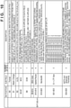
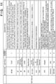
- EHT-SIG-A 1 and EHT-SIG-A 2 necessary for reception of PPDUs are included in the EHT-SIG-A 805.
- a group of subfields constituting the EHT-SIG-A 1 included in the EHT-SIG-A 805 and a group of subfields constituting the EHT-SIG-A 2 are illustrated in FIG. 10 and FIG. 11 , respectively.
- the EHT-STF 806 subsequent to the EHT-SIG-A 805 is an abbreviation of an EHT Short Training Field, and the main objective is to improve automatic gain control in MIMO transmission.
- the EHT-LTF 807 is an abbreviation of an EHT Long Training Field, and is used for the above-described frequency difference correction as well as propagation channel estimation.
- the data field 808 includes various kinds of data modulated in accordance with the modulation method indicated in the above-described EHT-SIG-A 1.
- the present embodiment it is possible to set a repetition number for EHT-LTF in a GI+LTF Size subfield of the EHT-SIG-A 1 ( FIG. 10 ) and set a repetition number that is larger than 4 ⁇ EHT-LTF.
- the repetition number for EHT-LTF is set to a number exceeding 4 in order to improve synchronization precision in transmission of slave triggers via noise suppression by averaging.
- the EHT ER PPDU illustrated in FIG. 9 is a PPDU used for when it is desired to extend the communication range, and is used for communication between an AP and a single AP/STA.
- the EHT ER PPDU includes L-STF 901, L-LTF 902, L-SIG 903, RL-SIG 904, EHT-SIG-A 905, EHT-STF 906, EHT-LTF 907, a data field 908, and a Packet extention 909. Out of these, the RL-SIG 904 is not necessary.
- the L-LTF 902 is arranged immediately after the L-STF 901, the L-SIG 903 is arranged immediately after the L-LTF 902, the EHT-SIG-A 905 is arranged after the L-SIG 903, the EHT-STF 906 is arranged immediately after the EHT-SIG-A 905, and the EHT-LTF 907 is arranged immediately after the EHT-STF 906.
- the fields from the L-STF 901, the L-LTF 902, the L-SIG 903, the RL-SIG 904, the EHT-SIG-A 905, the EHT-STF 906, and up to the EHT-LTF 907 are called a "preamble".
- EHT-SIG-A 905 it is possible, similarly to the ETH SU PPDU of FIG. 8 , to set a repetition number that is larger than 4 ⁇ EHT-LTF for GI+LTF Size in the EHT-SIG-A 1. Also, an EHT-LTF of the set number will be included in the EHT-LTF 907.
- the frame structures of the EHT SU PPDU and the EHT ER PPDU, which are PPDUs used in the IEEE 802.11 EHT standard, indicated in the present embodiment is used, it is possible to transmit EHT LTF at a repetition number exceeding 4. In other words, it is possible to increase synchronization precision by setting a large repetition number for EHT LTF at the time of transmission of a slave trigger, thereby improving communication performance in D-MIMO transmission.
- FIG. 8 and FIG. 9 illustrate frame structures that are backward compatible with the IEEE 802.11 a/b/g/n/ax standards, in a case where there is no need to ensure backward compatibility, L-STF and L-LTG fields may be omitted. EHT-STF and EHT-LTF may be inserted in place of these.
- configuration may be taken so as to increase a repetition number in any frame. For example, since transmission errors due to frequency differences are more likely to occur in higher order modulation such as 1048 QAM, configuration may be taken so as to set a repetition number of EHT LTF of a higher order modulation data frame.
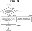
- FIG. 12 illustrates a processing procedure of the AP 103 (of the control unit 302), which is the master in this case. Description will be given below with reference to this figure.
- step S1201 the control unit 302 determines whether or not the D-MIMO slave trigger is to be transmitted. In a case where the determination in step S1201 is Yes, the control unit 302 advances the processing to step S1202, and generates a slave trigger in which the repetition number for LTF is a number exceeding 4 (may be 6 or 8). Also, in a case where the determination in step S1201 is No (the frame to be transmitted is other than a slave trigger), the control unit 302 advance the processing to step S1203, and generates a frame in which the repetition number for LTF is set to any number that can be set in the GI+LTF Size subfield. Then, in step S1204, the control unit 32 transmits the generated frame by controlling the communication unit 306.
- the repetition number for LTF of a slave trigger may be set to a value that is larger than other frames. For example, while the repetition number for LTF of a slave trigger is set to 6, the repetition number for LTF of other frames that do not need synchronization precision is set to 2. Accordingly, the repetition number for LTF of each frame may be set flexibly in accordance with necessary synchronization precision.
- the present invention can be implemented by processing of supplying a program for implementing one or more functions of the above-described embodiments to a system or apparatus via a network or storage medium, and causing one or more processors in the computer of the system or apparatus to read out and execute the program.
- the present invention can also be implemented by a circuit (for example, an ASIC) for implementing one or more functions.
Landscapes
- Engineering & Computer Science (AREA)
- Signal Processing (AREA)
- Computer Networks & Wireless Communication (AREA)
- Quality & Reliability (AREA)
- Mobile Radio Communication Systems (AREA)
- Radio Transmission System (AREA)
Abstract
Description
- The present invention relates to a communication device and a method for controlling the same, and a computer program.
- In recent years, Internet usage has been increasing year by year together with the development of information communication technologies, and various communication techniques are being developed in response to the increase in demand. In particular, wireless local area network (wireless LAN) techniques realize throughput improvement in Internet communications for packet data, audio, video, and the like by wireless LAN terminals, and various technological development is still being conducted actively.
- In the development of wireless LAN techniques, a lot of standardization work by the IEEE (Institute of Electrical and Electronics Engineers) 802, which is a standardization institution for wireless LAN techniques, plays an important role. The standards of wireless LAN communication are known as the IEEE 802.11 standards, and there are standards such as IEEE 802.11n/a/b/g/ac and IEEE 802.11ax. For example, IEEE 802.11ax implements a high peak throughput of up to 9.6 gigabits per second (Gbps) and additionally improves the communication speed under a congestion situation using OFDMA (Orthogonal Frequency-Division Multiple Access) (PTL 1).
- Recently, in order to further improve throughput, a study group called IEEE 802.11 EHT (Extremely High Throughput) has been formed as a subsequent standard of IEEE 802.11ax. Distributed MIMO is being considered as one measure for improving throughput which EHT aims to achieve. A characteristic of Distributed MIMO is in that a plurality of APs perform collaborative operation, and improvement in communication speed can be expected with an increase in the number of usable antennas. A method of synchronizing a plurality of APs using frames called slave triggers is being proposed as a method of implementing Distributed MIMO. In this method, a slave-AP detects frequency differences with respect to a slave trigger transmitted from a master-AP, and performs frequency correction so as to synchronize with the master-AP.
- [PTL 1] Japanese Patent Laid-Open No. 2018-50133
- In the above-described Distributed MIMO, synchronization between APs becomes necessary for a plurality of APs to perform collaborative operation. In a method in which slave triggers are used, a slave-AP detects frequency differences with respect to a slave trigger transmitted from a master-AP, and performs frequency correction so as to synchronize with the master-AP. This frequency correction processing is performed using a preamble signal included in a slave trigger. However, there was a problem that synchronization precision between APs would decrease by occurrence of residual frequency differences due to thermal noise and the like, thereby decreasing communication performance.
- The present invention has been made in consideration of the above problem, and provides a technique capable of increasing synchronization precision between APs in Distributed MIMO than ever before.
- In order to solve this problem, a communication device of the present invention comprises the following configuration, for example. In other words,
- a communication device that constitutes a wireless network by cooperating with another communication device,
- wherein the communication device has a transmission unit that transmits a frame for synchronization to the other communication device in order to cooperate with the other communication device, and
- the transmission unit includes:
- a setting unit that sets a value exceeding 4 as a repetition number for an EHT Long Training Field (EHT-LTF) in a preset position of an EHT Signal Field (EHT-SIG-A) of a frame for synchronization; and
- a generation unit that generates a frame for synchronization, the frame including EHT-LTFs whose quantity is the set repetition number,
- wherein the transmission unit transmits the generated frame for synchronization to the other communication device.
- According to the present invention, synchronization precision between APs in Distributed MIMO can be increased to be higher than ever before.
- Other features and advantages of the present invention will be apparent from the following description taken in conjunction with the accompanying drawings. Note that the same reference numerals denote the same or like components throughout the accompanying drawings.
- The accompanying drawings, which are incorporated in and constitute a part of the specification, illustrate embodiments of the invention and, together with the description, serve to explain principles of the invention.
- [
FIG. 1 ] A view illustrating an example of a network configuration. - [
FIG. 2 ] A view illustrating an example of a functional configuration of an AP. - [
FIG. 3 ] A view illustrating an example of a hardware configuration of the AP. - [
FIG. 4 ] A flowchart illustrating processing to be executed by a master-AP. - [
FIG. 5 ] A flowchart illustrating processing to be executed by a slave-AP. - [
FIG. 6 ] A sequence chart illustrating processing to be executed in a wireless communication network. - [
FIG. 7 ] A view illustrating an example of a configuration of a frequency difference detection unit. - [
FIG. 8 ] A view illustrating an example of a PHY frame structure of EHT SU PPDU. - [
FIG. 9 ] A view illustrating an example of a PHY frame structure of EHT ER PPDU. - [
FIG. 10 ] A table indicating a bit position and meaning of a subfield of EHT-SIG-A 1 within a frame. - [
FIG. 11 ] A table indicating a bit position and meaning of a subfield of EHT-SIG-A 2 within a frame. - [
FIG. 12 ] A flowchart illustrating an example of processing of the master-AP. - Hereinafter, embodiments will be described in detail with reference to the attached drawings. Note that the following embodiments are merely specific examples of the embodiments of the present invention, and do not limit the present invention. Although a plurality of features are described in the embodiments, not all of the plurality of features are essential to the present invention, and the plurality of features may be arbitrarily combined. Furthermore, in the accompanying drawings, the same reference numerals are assigned to the same or similar components, and a repetitive description thereof is omitted.
-
FIG. 1 illustrates an example of a network configuration according to a first embodiment. A wireless communication system ofFIG. 1 is a wireless network equipped with a plurality of APs (base stations; Access Points) 103 and 104 and a plurality of STAs (Stations) 105 and 106. - The
APs STAs circle 101, and a range that signals that the AP 104 transmits reach is indicated in acircle 102. Also, as illustrated, theAPs STAs APs control device 107. Regarding theAP control device 107, any one AP of a plurality of APs may have its function. Note that although in the present embodiment, it is assumed that the AP 103 will operate as the master-AP and theAP 104 will operate as the slave-AP, the method for setting which AP will operate as the master-AP does not particularly matter, and theAP control device 107 may set it in advance or the setting may be performed by an operation of a switch (not shown) arranged on each AP. - It should be noted that the configuration of the wireless communication network shown in
FIG. 1 is merely an example for illustrative purposes, and, for example, a network including a large number of EHT devices and legacy devices (communication devices that comply with an IEEE 802.11a/b/g/n/ax standard) in a wider area may be configured. Also, the arrangement of the communication devices is not limited to that shown inFIG. 1 , and the following argument is applicable to various positional relationships of the communication devices as well. Also, EHT may be understood as an abbreviation of Extreme High Throughput. -
FIG. 2 is a functional block diagram of theAPs APs LAN control unit 201, aframe generating unit 202, aframe control unit 203, and a UI (user interface)control unit 204. - The wireless
LAN control unit 201 may be configured to include one ormore antennas 205 for performing transmission/reception of wireless signals (radio frames) to and from another wireless LAN devices and a circuit, and a program for controlling these. The wirelessLAN control unit 201 executes communication control of a wireless LAN based on frames generated by theframe generating unit 202 in accordance with the standard of the IEEE802.11 series. - The
frame generating unit 202 generates frames to be transmitted by the wirelessLAN control unit 201 based on instructions of theframe control unit 203. Although details will be made clear from descriptions to be given later, theframe control unit 203 of theAP 103, which is the master, in a case where a frame to be transmitted is a slave trigger for D-MIMO, performs the following settings for theframe generating unit 202. - Set a value exceeding 4 as a repetition number for an EHT Long Training Field (EHT-LTF) in a preset position (refer to
FIGS. 9 and10 ) of an EHT Signal Field (EHT-SIG-A) of a frame. - Perform an instruction for generating EHT-LTFs whose quantity is the set repetition number.
- The
frame generating unit 202 generates a slave trigger for D-MIMO in accordance with this instruction. - Note that the
frame generating unit 202 may create frames independently of instructions of theframe control unit 203. - The
UI control unit 204 accepts operations with respect to an input unit 304 (FIG. 3 ) by a user (not shown) of theAPs FIG. 3 ). -
FIG. 3 illustrates hardware configurations of theAPs APs storage unit 301, acontrol unit 302, afunctional unit 303, theinput unit 304, theoutput unit 305, and acommunication unit 306, and one ormore antennas 205. - The
storage unit 301 is configured by both or either one of a ROM and a RAM, and stores various kinds of information such as programs for performing various operations to be described later and communication parameters for wireless communication. Note that other than the memories such as a ROM and a RAM, a storage medium such as a flexible disk, a hard disk, an optical disk, a magnetooptical disk, a CD-ROM, a CD-R, a magnetic tape, a nonvolatile memory card, or a DVD may be used as thestorage unit 301. - The
control unit 302 is configured by, for example, a processor such as a CPU or an MPU, an ASIC (application-specific integrated circuit), a DSP (digital signal processor), an FPGA (field-programmable gate array), or the like. Here, CPU is an acronym for a Central Processing Unit, and MPU is an acronym for a Micro Processing Unit. Thecontrol unit 302 controls the entire theAPs storage unit 301. Note that thecontrol unit 302 may control the entire theAPs storage unit 301 and the OS (Operating System). - Also, the
control unit 302 executes predetermined processing such as image capturing, printing, and projection by controlling thefunctional unit 303. Thefunctional unit 303 is hardware for theAPs APs functional unit 303 is an image capturing unit and performs image capturing processing. Also, for example, in a case where theAPs functional unit 303 is a printing unit and performs printing processing. Also, for example, in a case where theAPs functional unit 303 is a projection unit and performs projection processing. Data to be processed by thefunctional unit 303 may be data stored in thestorage unit 301, or may be data communicated from an STA or another AP via thecommunication unit 306 to be described later. - The
input unit 304 performs acceptance of various operations from the user. Theoutput unit 305 performs various outputs to the user. Here, outputs by theoutput unit 305 include at least one of displaying on a screen, audio output by a loudspeaker, vibration output, and the like. Note that both theinput unit 304 and theoutput unit 305 may be implemented by one module, like a touch panel. - The
communication unit 306 performs control (includes modulation and encoding processing) of wireless communication complying with the IEEE 802.11 EHT standard, control of wireless communication complying with Wi-Fi, and control of IP (Internet Protocol) communication. Also, thecommunication unit 306 performs transmission/reception of radio signals for wireless communication by controlling the one ormore antennas 205. In that case, MIMO (Multi Input Multi Output) communication that uses spatial streams becomes possible. TheAPs communication unit 306. Note that the functions of each configuration element illustrated inFIG. 3 may be implemented partially by software. - The functional configurations and the hardware configurations of the
STAs FIG. 2 ) and the hardware configurations (FIG. 3 ) of theAPs STAs LAN control unit 201, theframe generating unit 202, theframe control unit 203, and theUI control unit 204, and include, as a hardware configuration, thestorage unit 301, thecontrol unit 302, thefunctional unit 303, theinput unit 304, theoutput unit 305, thecommunication unit 306, and the one ormore antennas 205. - Next, a flow of processing to be executed by the
AP 103 configured as described above and a sequence of processing to be executed by the wireless communication system illustrated inFIG. 1 will be described with reference toFIG. 4 to FIG. 6 . Here, description will be given for an example of operation in which theAPs STA 105 by collaborative operation. Each ofFIG. 4 andFIG. 5 illustrate a flowchart indicating processing to be executed by theAPs FIG. 4 andFIG. 5 may be realized by thecontrol unit 302 of each of theAPs storage unit 301. Also,FIG. 6 illustrates a sequence chart of processing to be executed in the wireless communication system. - In the sequence chart of
FIG. 6 , theAPs AP 104, which is the slave-AP, has to synchronize with theAP 103, which is the master-AP. For this synchronization processing, theAP 103 transmits a slave trigger to theAP 104 prior to data frame transmission. Although in the present embodiment, it is assumed that slave triggers are transmitted based on trigger frames of the IEEE 802.11ax standard, the present invention is not limited to this. Note that it is assumed that CSI (Channel State Information) for theAPs STA 105 are acquired in advance. - The
AP 103, which is the master, transmits a slave trigger to the AP 104 (stepS 401; F601). TheAP 104, which is the slave, detects a frequency difference from the received slave trigger and corrects the frequency to synchronize with the AP 103 (step S501). - Here, frequency correction processing will be described with reference to
FIG. 7. FIG. 7 is a block diagram illustrating an example of a configuration of a frequencydifference detection unit 701. The frequencydifference detection unit 701 is included in the wirelessLAN control unit 201. - The frequency
difference detection unit 701 detects frequency differences using a repetition signal section included in a received signal. In the IEEE 802.11 standard, STF (Short Training Field) and LTF (Long Training Field) are specified as repetition signals. - The
communication unit 306 of theAP 104 generates an in-phase wave detection axis signal (hereinafter, I signal) and a quadrature wave detection axis signal (hereinafter, Q signal) by performing orthogonal demodulation of a wireless signal received via theantenna 205 and generates a signal P(t) to be supplied to the frequencydifference detection unit 701. - The frequency
difference detection unit 701 supplies the inputted signal P(t) to a multiplyingunit 702 and adelay unit 703. Here, if a frequency difference between theAP 103 and theAP 104 is set as Δf, P(t) can be expressed in the following Expression (1).
- The
delay unit 703 generates a delay signal P(t-T) which is the inputted signal P(t) delayed by a repetition signal period T and outputs it to acomplex conjugating unit 704. - STF and LTF are designed such that T=n/f. Accordingly, the delay signal P(t-T) can be expressed in the following Equation (2) and will be a signal in which the phase of the input signal P(t) is advanced by Δθ=2×π×Δf×T.

- The
complex conjugating unit 704 generates a complex conjugate signal P*(t-T) of the delay signal P(t-T) and outputs it to the multiplyingunit 702. - The multiplying
unit 702 performs complex multiplication of the input signal P(t) and the complex conjugate signal P*(t-T) and outputs the multiplication result to a frequencyerror calculating unit 705. The multiplication result is expressed by Expression (3).
- The frequency
error calculating unit 705 calculates this Δθ by performing an ARCTAN calculation on the inputted multiplication result and obtains a frequency difference Δf. Thecommunication unit 306 corrects a frequency in the transmission/reception processing thereafter based on Δf obtained in the frequencydifference detection unit 701. This frequency correction method can be realized by multiplying exp(j×2×π×Δf×t) with the I signal and the Q signal. Alternative, configuration may be taken such that an oscillation source is configured by a variable control oscillator, and Δf correction is performed to the frequency thereof. Note that the obtained frequency difference Δf has a noise component due to thermal noise and the like. For suppression of this noise component, averaging processing is effective. For example, a noise component can be suppressed by obtaining an average within a range of the repetition signal period T. Also, it is possible to further suppress a noise component by increasing a repetition number of repetition signals and obtaining an average of a plurality of repetition signals. As described later, in the present embodiment, in slave trigger for D-MIMO transmission, in which high-precision synchronization is required, synchronization precision is improved by increasing the number of LTFs. - Description will return to that of
FIG. 6 , and theAP 103 and theAP 104 perform D-MIMO transmission of a data frame to theSTA 105 at a synchronized timing (steps S402, S502, and F602). - An example of a structure of a PHY (physical) frame of a PPDU specified by the IEEE 802.11 EHT standard transmitted by the above-described sequence is illustrated in
FIG. 8 andFIG. 9 . Note that PPDU is an abbreviation of Physical Layer (PHY) Protocol Data Unit. Although it is assumed that slave triggers are transmitted by either of the PHY frames illustrated inFIG. 8 andFIG. 9 , configuration may be taken so as to separately specify a PHY frame for slave triggers. -
FIG. 8 illustrates an example of a structure of a PHY frame of an EHT SU PPDU, which is a PPDU for single-user (SU) communication (between an AP and a single AP/STA).FIG. 9 illustrates an example of a structure of a PHY frame of an EHT ER PPDU, which is a PPDU for communication in an extended range (communication range). EHT ER PPDUs are used for communication between an AP and a single AP/STA. - There are STF (Short Training Field), LTF (Long Term Field), and SIG (Signal Field) as information that PPDUs include in both
FIG. 8 andFIG. 9 . Using the example ofFIG. 8 , L(Legacy)-STF 801, L-LTF 802, and L-SIG 803, which are backward compatible with the IEEE 802.11a/b/g/n/ax standards are included in the head portion of the PPDU. Also, EHT-SIG-A 805, EHT-STF 806, and EHT-LTF 807 for the EHT standard are included commonly in each PPDU. - The L-
STF 801 is used for PHY frame signal detection, automatic gain control (AGC), and timing detection, and the like. The L-LTF 802 arranged immediately after the L-STF 801 is used for high-precision frequency/time synchronization, CSI acquisition, and the like. The L-SIG 803 arranged immediately after the L-LTF 802 is used for transmission of control information, which includes information of data transmission rate and PHY frame length. A legacy device complying with the IEEE 802.11 a/b/g/n/ax standards can decode data of the above various legacy fields (L-STF 801, L-LTF 802, and L-SIG 803). The various legacy fields are similarly included in the PPDU illustrated inFIG. 9 . - The frame of the EHT SU PPDU illustrated in
FIG. 8 includes RL-SIG 804, the EHT-SIG-A 805, the EHT-STF 806, the EHT-LTF 807, adata field 808, aPacket extention 809 subsequently to the above L-STF 801, L-LTF 802, and L-SIG 803. Out of these, the RL-SIG 804 may be omitted. The EHT-SIG-A 805 is arranged after the L-SIG 803, the EHT-STF 806 is arranged immediately after the EHT-SIG-A 805, and the EHT-LTF 807 is arranged immediately after the EHT-STF 806. Note that the fields from the L-STF 801, the L-LTF 802, the L-SIG 803, the RL-SIG 804, the EHT-SIG-A 805, the EHT-STF 806, and up to the EHT-LTF 807 are called a "preamble". - Information such as EHT-SIG-
A 1 and EHT-SIG-A 2 necessary for reception of PPDUs are included in the EHT-SIG-A 805. A group of subfields constituting the EHT-SIG-A 1 included in the EHT-SIG-A 805 and a group of subfields constituting the EHT-SIG-A 2 are illustrated inFIG. 10 andFIG. 11 , respectively. - The EHT-
STF 806 subsequent to the EHT-SIG-A 805 is an abbreviation of an EHT Short Training Field, and the main objective is to improve automatic gain control in MIMO transmission. The EHT-LTF 807 is an abbreviation of an EHT Long Training Field, and is used for the above-described frequency difference correction as well as propagation channel estimation. Thedata field 808 includes various kinds of data modulated in accordance with the modulation method indicated in the above-described EHT-SIG-A 1. - In the present embodiment, it is possible to set a repetition number for EHT-LTF in a GI+LTF Size subfield of the EHT-SIG-A 1 (
FIG. 10 ) and set a repetition number that is larger than 4×EHT-LTF. Note that although it is assumed that it is possible to set 6×EHT-LTF or 8×EHT-LTF inFIG. 10 , the present invention is not limited to this, and configuration may be taken so as to be able to set 5×EHT-LTF and 16×EHT-LTF. In the present embodiment, the repetition number for EHT-LTF is set to a number exceeding 4 in order to improve synchronization precision in transmission of slave triggers via noise suppression by averaging. - The EHT ER PPDU illustrated in
FIG. 9 , as described above, is a PPDU used for when it is desired to extend the communication range, and is used for communication between an AP and a single AP/STA. The EHT ER PPDU includes L-STF 901, L-LTF 902, L-SIG 903, RL-SIG 904, EHT-SIG-A 905, EHT-STF 906, EHT-LTF 907, adata field 908, and aPacket extention 909. Out of these, the RL-SIG 904 is not necessary. The L-LTF 902 is arranged immediately after the L-STF 901, the L-SIG 903 is arranged immediately after the L-LTF 902, the EHT-SIG-A 905 is arranged after the L-SIG 903, the EHT-STF 906 is arranged immediately after the EHT-SIG-A 905, and the EHT-LTF 907 is arranged immediately after the EHT-STF 906. Note that the fields from the L-STF 901, the L-LTF 902, the L-SIG 903, the RL-SIG 904, the EHT-SIG-A 905, the EHT-STF 906, and up to the EHT-LTF 907 are called a "preamble". Description will be omitted for information included in each field as they are of the same content as the EHT SU PPDU illustrated inFIG. 8 . Note that in the EHT-SIG-A 905, it is possible, similarly to the ETH SU PPDU ofFIG. 8 , to set a repetition number that is larger than 4×EHT-LTF for GI+LTF Size in the EHT-SIG-A 1. Also, an EHT-LTF of the set number will be included in the EHT-LTF 907. - As described above, if the frame structures of the EHT SU PPDU and the EHT ER PPDU, which are PPDUs used in the IEEE 802.11 EHT standard, indicated in the present embodiment is used, it is possible to transmit EHT LTF at a repetition number exceeding 4. In other words, it is possible to increase synchronization precision by setting a large repetition number for EHT LTF at the time of transmission of a slave trigger, thereby improving communication performance in D-MIMO transmission.
- Note that although
FIG. 8 andFIG. 9 illustrate frame structures that are backward compatible with the IEEE 802.11 a/b/g/n/ax standards, in a case where there is no need to ensure backward compatibility, L-STF and L-LTG fields may be omitted. EHT-STF and EHT-LTF may be inserted in place of these. - Also, although in the present embodiment, it is assumed that a repetition number for EHT LTF of a slave trigger is increased, the present invention is not limited to this, and in a transmission mode in which high-precision synchronization is required, configuration may be taken so as to increase a repetition number in any frame. For example, since transmission errors due to frequency differences are more likely to occur in higher order modulation such as 1048 QAM, configuration may be taken so as to set a repetition number of EHT LTF of a higher order modulation data frame.
- Also, configuration may also be taken such that when the
AP 103, which is the master, transmits a slave trigger, it is determined whether or not that is a D-MIMO slave trigger and a repetition number for LTF is decided thereupon.FIG. 12 illustrates a processing procedure of the AP 103 (of the control unit 302), which is the master in this case. Description will be given below with reference to this figure. - In step S1201, the
control unit 302 determines whether or not the D-MIMO slave trigger is to be transmitted. In a case where the determination in step S1201 is Yes, thecontrol unit 302 advances the processing to step S1202, and generates a slave trigger in which the repetition number for LTF is a number exceeding 4 (may be 6 or 8). Also, in a case where the determination in step S1201 is No (the frame to be transmitted is other than a slave trigger), thecontrol unit 302 advance the processing to step S1203, and generates a frame in which the repetition number for LTF is set to any number that can be set in the GI+LTF Size subfield. Then, in step S1204, the control unit 32 transmits the generated frame by controlling thecommunication unit 306. Note that in the processing of steps S1202 and S1203, the repetition number for LTF of a slave trigger may be set to a value that is larger than other frames. For example, while the repetition number for LTF of a slave trigger is set to 6, the repetition number for LTF of other frames that do not need synchronization precision is set to 2. Accordingly, the repetition number for LTF of each frame may be set flexibly in accordance with necessary synchronization precision. - The present invention can be implemented by processing of supplying a program for implementing one or more functions of the above-described embodiments to a system or apparatus via a network or storage medium, and causing one or more processors in the computer of the system or apparatus to read out and execute the program. The present invention can also be implemented by a circuit (for example, an ASIC) for implementing one or more functions.
- The present invention is not limited to the above embodiments and various changes and modifications can be made within the spirit and scope of the present invention. Therefore, to apprise the public of the scope of the present invention, the following claims are made.
- This application claims priority based on
Japanese Patent Application No. 2019-085799 filed April 26, 2019
Claims (9)
- A communication device characterized by constituting a wireless network by cooperating with another communication device,wherein the communication device has a transmission unit that transmits a frame for synchronization to the other communication device in order to cooperate with the other communication device, andthe transmission unit includes:a setting unit that sets a value exceeding 4 as a repetition number for an EHT Long Training Field (EHT-LTF) in a preset position of an EHT Signal Field (EHT-SIG-A) of a frame for synchronization; anda generation unit that generates a frame for synchronization, the frame including EHT-LTFs whose quantity is the set repetition number,wherein the transmission unit transmits the generated frame for synchronization to the other communication device.
- The communication device according to claim 1, characterized in that the transmission unit transmits a frame for synchronization for performing communication by Distributed MIMO.
- The communication device according to claim 1 or 2, characterized in that the transmission unit includes:a determination unit that determines whether or not a frame for synchronization to be transmitted is a frame for performing communication by Distributed MIMO,wherein the setting unit, in a case where it is determined by the determination unit that it is a frame for performing communication by Distributed MIMO, sets the repetition number for the EHT-LTF to be larger than in a case of another frame.
- The communication device according to any one of claims 1 to 3, characterized in thatthe frame is a physical (PHY) frame having a preamble and a data field,wherein the preamble includes:a Legacy Short Training Field (L-STF);a Legacy Long Training Field (L-LTF) arranged immediately after the L-STF in a frame;a Legacy Signal Field (L-SIG) arranged immediately after the L-LTF in the frame;an EHT Signal Field (EHT-SIG-A) arranged after the L-SIG in the frame;an EHT Short Training Field (EHT-STF) arranged after immediately after the EHT-SIG-A in the frame;an EHT Long Training Field (EHT-LTF) arranged immediately after the EHT-STF in the frame,wherein the EHT-SIG-A includes a field in which a value exceeding 4 can be set as a repetition number for an EHT-LTF, andthe frame includes an EHT-LTF for the repetition number indicated by the field.
- A method for controlling a communication device characterized by constituting a wireless network by cooperating with another communication device, the method comprising:transmitting a frame for synchronization to the other communication device in order to cooperate with the other communication device, andthe transmittingsets a value exceeding 4 as a repetition number for an EHT Long Training Field (EHT-LTF) in a preset position of an EHT Signal Field (EHT-SIG-A) of a frame for synchronization; andgenerates a frame for synchronization, the frame including EHT-LTFs whose quantity is the set repetition number,wherein the transmitting transmits the generated frame for synchronization to the other communication device.
- A communication device characterized by constituting a wireless network by cooperating with another communication device,wherein the communication device has a transmission unit that transmits a frame for synchronization to the other communication device in order to cooperate with the other communication device, andthe transmission unit includes:a generation unit that generates a frame whose repetition number for an EHT Long Training Field (EHT-LTF) is larger when transmitting a synchronization frame for performing communication by Distributed MIMO than in a case of transmitting a frame other than that,wherein the transmission unit transmits the generated frame to the other communication device.
- A method for controlling a communication device characterized by constituting a wireless network by cooperating with another communication device, the method comprising:transmitting a frame for synchronization to the other communication device in order to cooperate with the other communication device, andthe transmission includes:generating a frame whose repetition number for an EHT Long Training Field (EHT-LTF) is larger when transmitting a synchronization frame for performing communication by Distributed MIMO than in a case of transmitting a frame other than that, andthe transmitting transmits the generated frame to the other communication device.
- A computer program that is read and executed by a processor in a communication device that constitutes a wireless network by cooperating with another communication device, characterized in that the program causes the communication device to execute:transmitting a frame for synchronization to the other communication device in order to cooperate with the other communication device, andwherein for the transmitting:a value exceeding 4 is set as a repetition number for an EHT Long Training Field (EHT-LTF) in a preset position of an EHT Signal Field (EHT-SIG-A) of a frame for synchronization; anda frame for synchronization is generated, the frame including EHT-LTFs whose quantity is the set repetition number,wherein the transmitting transmits the generated frame for synchronization to the other communication device.
- A computer program that is read and executed by a processor in a communication device that constitutes a wireless network by cooperating with another communication device, characterized in that the program causes the communication device to execute:transmitting a frame for synchronization to the other communication device in order to cooperate with the other communication device, andwherein the transmitting:includes generating a frame whose repetition number for an EHT Long Training Field (EHT-LTF) is larger when transmitting a synchronization frame for performing communication by Distributed MIMO than in a case of transmitting a frame other than that, andthe transmission transmits the frame that was generated to the other communication device
Applications Claiming Priority (2)
| Application Number | Priority Date | Filing Date | Title |
|---|---|---|---|
| JP2019085799A JP7292091B2 (en) | 2019-04-26 | 2019-04-26 | Communication device and its control method and program |
| PCT/JP2020/007316 WO2020217691A1 (en) | 2019-04-26 | 2020-02-25 | Communication device, method for controlling same, and computer program |
Publications (2)
| Publication Number | Publication Date |
|---|---|
| EP3962146A1 true EP3962146A1 (en) | 2022-03-02 |
| EP3962146A4 EP3962146A4 (en) | 2023-01-18 |
Family
ID=72942413
Family Applications (1)
| Application Number | Title | Priority Date | Filing Date |
|---|---|---|---|
| EP20795162.5A Pending EP3962146A4 (en) | 2019-04-26 | 2020-02-25 | COMMUNICATION DEVICE, CORRESPONDING CONTROL METHOD AND COMPUTER PROGRAM |
Country Status (5)
| Country | Link |
|---|---|
| US (2) | US12184359B2 (en) |
| EP (1) | EP3962146A4 (en) |
| JP (2) | JP7292091B2 (en) |
| CN (2) | CN113748702A (en) |
| WO (1) | WO2020217691A1 (en) |
Family Cites Families (13)
| Publication number | Priority date | Publication date | Assignee | Title |
|---|---|---|---|---|
| KR20110082685A (en) * | 2010-01-12 | 2011-07-20 | 삼성전자주식회사 | A preamble generation method of a multi-user multi-input / output system, a data transmission device and a terminal employing the method |
| US9326158B2 (en) * | 2011-08-20 | 2016-04-26 | Qualcomm Incorporated | Method and apparatus for communicating with extended range in a wireless network |
| KR101874124B1 (en) * | 2011-11-09 | 2018-07-03 | 한국전자통신연구원 | Apparatus and method for transmitting/receiving data in communication system |
| WO2013122377A1 (en) * | 2012-02-14 | 2013-08-22 | 엘지전자 주식회사 | Method for transmitting data units in wireless lan systems and apparatus for supporting same |
| US9439161B2 (en) * | 2013-07-17 | 2016-09-06 | Qualcomm Incorporated | Physical layer design for uplink (UL) multiuser multiple-input, multiple-output (MU-MIMO) in wireless local area network (WLAN) systems |
| US9826532B1 (en) * | 2015-02-09 | 2017-11-21 | Marvell International Ltd. | Orthogonal frequency division multiple access resource request |
| JP6624194B2 (en) * | 2015-02-27 | 2019-12-25 | ソニー株式会社 | Information processing equipment |
| CN105120520B (en) * | 2015-07-17 | 2019-04-19 | 魅族科技(中国)有限公司 | The method and apparatus that data are transmitted in Wireless LAN |
| JP2018050133A (en) | 2016-09-20 | 2018-03-29 | キヤノン株式会社 | Communication device, control method, and program |
| WO2019045708A1 (en) * | 2017-08-30 | 2019-03-07 | Intel IP Corporation | Methods and systems for next generation wifi |
| JP6878249B2 (en) | 2017-11-09 | 2021-05-26 | 洋 千田 | Panel material and panel material manufacturing method |
| US11363549B2 (en) * | 2018-08-29 | 2022-06-14 | Avago Technologies International Sales Pte. Limited | Frame formats for distributed MIMO |
| WO2020149717A1 (en) * | 2019-01-18 | 2020-07-23 | 엘지전자 주식회사 | Signal transmission using plurality of aps in wireless lan system |
-
2019
- 2019-04-26 JP JP2019085799A patent/JP7292091B2/en active Active
-
2020
- 2020-02-25 WO PCT/JP2020/007316 patent/WO2020217691A1/en not_active Ceased
- 2020-02-25 EP EP20795162.5A patent/EP3962146A4/en active Pending
- 2020-02-25 CN CN202080031279.3A patent/CN113748702A/en active Pending
- 2020-02-25 CN CN202510106549.7A patent/CN119922562A/en not_active Withdrawn
-
2021
- 2021-10-22 US US17/508,777 patent/US12184359B2/en active Active
-
2023
- 2023-06-05 JP JP2023092678A patent/JP7493654B2/en active Active
-
2024
- 2024-11-22 US US18/957,455 patent/US20250088222A1/en active Pending
Also Published As
| Publication number | Publication date |
|---|---|
| JP2020182181A (en) | 2020-11-05 |
| US12184359B2 (en) | 2024-12-31 |
| CN119922562A (en) | 2025-05-02 |
| WO2020217691A1 (en) | 2020-10-29 |
| CN113748702A (en) | 2021-12-03 |
| US20250088222A1 (en) | 2025-03-13 |
| JP2023105051A (en) | 2023-07-28 |
| EP3962146A4 (en) | 2023-01-18 |
| US20220045724A1 (en) | 2022-02-10 |
| JP7292091B2 (en) | 2023-06-16 |
| JP7493654B2 (en) | 2024-05-31 |
Similar Documents
| Publication | Publication Date | Title |
|---|---|---|
| EP3729755B1 (en) | Method and device for transmitting ofdm signal, and method and device for receiving ofdm signal | |
| JP7522894B2 (en) | COMMUNICATION DEVICE, INFORMATION PROCESSING DEVICE, AND CONTROL METHOD AND PROGRAM THEREOF | |
| JP7695318B2 (en) | COMMUNICATION DEVICE, COMMUNICATION METHOD, AND PROGRAM | |
| CN113491147B (en) | Communication device, communication method and storage medium | |
| CN113519181B (en) | Communication device, communication method, and computer-readable storage medium | |
| WO2021090733A1 (en) | Communication device, communication method, and program | |
| JP2023053119A (en) | Communication device, communication method, and program | |
| CN113615243A (en) | Communication apparatus, control method, and program | |
| US8493907B2 (en) | Frequency offset estimation scheme in scheduled based wireless system | |
| EP3689051B1 (en) | Device and method for use in wireless communications | |
| EP3962146A1 (en) | Communication device, method for controlling same, and computer program | |
| US10892916B2 (en) | Channel estimation method and circuit | |
| JP2020141308A (en) | Communication device and its communication method, information processing device and its control method, and program | |
| WO2024014256A1 (en) | Communication device, communication method, and program |
Legal Events
| Date | Code | Title | Description |
|---|---|---|---|
| STAA | Information on the status of an ep patent application or granted ep patent |
Free format text: STATUS: THE INTERNATIONAL PUBLICATION HAS BEEN MADE |
|
| PUAI | Public reference made under article 153(3) epc to a published international application that has entered the european phase |
Free format text: ORIGINAL CODE: 0009012 |
|
| STAA | Information on the status of an ep patent application or granted ep patent |
Free format text: STATUS: REQUEST FOR EXAMINATION WAS MADE |
|
| 17P | Request for examination filed |
Effective date: 20211126 |
|
| AK | Designated contracting states |
Kind code of ref document: A1 Designated state(s): AL AT BE BG CH CY CZ DE DK EE ES FI FR GB GR HR HU IE IS IT LI LT LU LV MC MK MT NL NO PL PT RO RS SE SI SK SM TR |
|
| DAV | Request for validation of the european patent (deleted) | ||
| DAX | Request for extension of the european patent (deleted) | ||
| REG | Reference to a national code |
Ref country code: DE Ref legal event code: R079 Free format text: PREVIOUS MAIN CLASS: H04W0016280000 Ipc: H04B0007260000 |
|
| A4 | Supplementary search report drawn up and despatched |
Effective date: 20221215 |
|
| RIC1 | Information provided on ipc code assigned before grant |
Ipc: H04B 7/0413 20170101ALI20221209BHEP Ipc: H04B 7/024 20170101ALI20221209BHEP Ipc: H04W 84/12 20090101ALI20221209BHEP Ipc: H04W 28/16 20090101ALI20221209BHEP Ipc: H04W 16/28 20090101ALI20221209BHEP Ipc: H04W 56/00 20090101ALI20221209BHEP Ipc: H04B 7/26 20060101AFI20221209BHEP |
|
| STAA | Information on the status of an ep patent application or granted ep patent |
Free format text: STATUS: EXAMINATION IS IN PROGRESS |
|
| 17Q | First examination report despatched |
Effective date: 20251128 |
|
| STAA | Information on the status of an ep patent application or granted ep patent |
Free format text: STATUS: THE APPLICATION HAS BEEN WITHDRAWN |