EP3689051B1 - Device and method for use in wireless communications - Google Patents
Device and method for use in wireless communications Download PDFInfo
- Publication number
- EP3689051B1 EP3689051B1 EP17825860.4A EP17825860A EP3689051B1 EP 3689051 B1 EP3689051 B1 EP 3689051B1 EP 17825860 A EP17825860 A EP 17825860A EP 3689051 B1 EP3689051 B1 EP 3689051B1
- Authority
- EP
- European Patent Office
- Prior art keywords
- ofdm
- transmission
- wlan
- ofdm signal
- signals
- Prior art date
- Legal status (The legal status is an assumption and is not a legal conclusion. Google has not performed a legal analysis and makes no representation as to the accuracy of the status listed.)
- Active
Links
- 238000000034 method Methods 0.000 title claims description 34
- 238000004891 communication Methods 0.000 title description 24
- 230000005540 biological transmission Effects 0.000 claims description 82
- 230000001360 synchronised effect Effects 0.000 claims description 27
- 125000004122 cyclic group Chemical group 0.000 claims description 16
- 238000004590 computer program Methods 0.000 claims description 7
- 239000000969 carrier Substances 0.000 claims 3
- 238000012545 processing Methods 0.000 description 17
- 238000010586 diagram Methods 0.000 description 15
- 230000006870 function Effects 0.000 description 8
- 230000002452 interceptive effect Effects 0.000 description 6
- 230000000116 mitigating effect Effects 0.000 description 5
- 230000001052 transient effect Effects 0.000 description 5
- 230000009467 reduction Effects 0.000 description 4
- 230000008901 benefit Effects 0.000 description 3
- 150000001875 compounds Chemical class 0.000 description 3
- 238000005516 engineering process Methods 0.000 description 3
- 239000000463 material Substances 0.000 description 3
- 108700026140 MAC combination Proteins 0.000 description 2
- 238000003491 array Methods 0.000 description 2
- 230000001413 cellular effect Effects 0.000 description 2
- 238000012937 correction Methods 0.000 description 2
- 238000013500 data storage Methods 0.000 description 2
- 230000001419 dependent effect Effects 0.000 description 2
- 239000000796 flavoring agent Substances 0.000 description 2
- 235000019634 flavors Nutrition 0.000 description 2
- 239000007787 solid Substances 0.000 description 2
- 238000012549 training Methods 0.000 description 2
- 239000004606 Fillers/Extenders Substances 0.000 description 1
- 238000010276 construction Methods 0.000 description 1
- 230000001934 delay Effects 0.000 description 1
- 230000007613 environmental effect Effects 0.000 description 1
- 230000006872 improvement Effects 0.000 description 1
- 238000010348 incorporation Methods 0.000 description 1
- 230000007774 longterm Effects 0.000 description 1
- 239000003550 marker Substances 0.000 description 1
- 238000005259 measurement Methods 0.000 description 1
- 239000000203 mixture Substances 0.000 description 1
- 238000012986 modification Methods 0.000 description 1
- 230000004048 modification Effects 0.000 description 1
- 230000003287 optical effect Effects 0.000 description 1
- 238000005457 optimization Methods 0.000 description 1
- 230000002093 peripheral effect Effects 0.000 description 1
- 230000008569 process Effects 0.000 description 1
- 230000004044 response Effects 0.000 description 1
- 230000002441 reversible effect Effects 0.000 description 1
- 239000004065 semiconductor Substances 0.000 description 1
- 238000012360 testing method Methods 0.000 description 1
Images


Classifications
-
- H—ELECTRICITY
- H04—ELECTRIC COMMUNICATION TECHNIQUE
- H04W—WIRELESS COMMUNICATION NETWORKS
- H04W56/00—Synchronisation arrangements
- H04W56/0005—Synchronisation arrangements synchronizing of arrival of multiple uplinks
-
- H—ELECTRICITY
- H04—ELECTRIC COMMUNICATION TECHNIQUE
- H04W—WIRELESS COMMUNICATION NETWORKS
- H04W56/00—Synchronisation arrangements
- H04W56/001—Synchronization between nodes
-
- H—ELECTRICITY
- H04—ELECTRIC COMMUNICATION TECHNIQUE
- H04W—WIRELESS COMMUNICATION NETWORKS
- H04W56/00—Synchronisation arrangements
- H04W56/001—Synchronization between nodes
- H04W56/0015—Synchronization between nodes one node acting as a reference for the others
-
- H—ELECTRICITY
- H04—ELECTRIC COMMUNICATION TECHNIQUE
- H04W—WIRELESS COMMUNICATION NETWORKS
- H04W56/00—Synchronisation arrangements
- H04W56/004—Synchronisation arrangements compensating for timing error of reception due to propagation delay
- H04W56/0045—Synchronisation arrangements compensating for timing error of reception due to propagation delay compensating for timing error by altering transmission time
-
- H—ELECTRICITY
- H04—ELECTRIC COMMUNICATION TECHNIQUE
- H04W—WIRELESS COMMUNICATION NETWORKS
- H04W84/00—Network topologies
- H04W84/02—Hierarchically pre-organised networks, e.g. paging networks, cellular networks, WLAN [Wireless Local Area Network] or WLL [Wireless Local Loop]
- H04W84/10—Small scale networks; Flat hierarchical networks
- H04W84/12—WLAN [Wireless Local Area Networks]
Definitions
- the present invention in some embodiments thereof, relates to a device, method and program product for use in wireless communications, more specifically in some embodiments, in one or more Wireless Local Area Networks (WLANs) in which a plurality of WLAN frames are to be respectively transmitted from different transmission addresses to different reception addresses.
- WLANs Wireless Local Area Networks
- WLANs there may be one or more WLANs, each of which, or which collectively, service two or more WLAN devices, having different addresses that receive a respective two or more WLAN frames.
- the WLAN frames may be transmitted by WLAN devices that are each at different addresses.
- mutual interference when such transmissions overlap in time, especially in cases where the transmitting and/or receiving WLAN devices are in relatively close proximity to each other.
- Wi-Fi protocols (defined by the IEEE 802.11 suite of standards, herein referred to as 802.11) are popularly employed by many modern devices for WLAN communication.
- Wi-Fi protocols are becoming used in increasingly dense environments, there has been an effort to establish flavors of the protocol, e.g. 802.11ax, that operate well in such environments.
- 802.11ax the protocol that operate well in such environments.
- transmissions being needed in increasingly dense environments, there remains a need for new ways of providing for spatial reuse.
- US 2014/153421 A1 describes a method for optimization of branch synchronization node determination in a peer-to-peer network.
- US 20157327291 A1 describes a method for increasing reuse in wireless communications.
- the present invention is defined by the appended claims and limited by the scope of the claims. Embodiments referred to in this description and not fully falling within the scope of the appended claims are examples suitable for understanding the present invention.
- the present invention in some embodiments thereof, relates to a device, method and program product for use in wireless communications, more specifically in some embodiments, in one or more WLANs in which a plurality of WLAN frames are to be respectively transmitted from different transmission addresses to different reception addresses.
- the present inventors understand that previously in wireless local area network communications, when different devices (for example, but not necessarily) access points transmit WLAN frames addressed to different receivers, there is no synchronization in the transmissions of the WLAN frames.
- Each transmitting device operates the transmission independently of the other transmitting device, and this can lead to interference at any one of the receivers if they are in relatively close proximity to each other whereby the receivers receives both WLAN frames.
- They present inventors have recognized that this mitigated can be solved by synchronizing transmission of the WLAN frames.
- synchronization information is determined for each of a plurality of OFDM signals in a respective plurality of WLAN frames.
- the WLAN frames are respectively transmitted from different transmission addresses, for example by different access points, and respectively define different reception addresses to be processed by different receivers, for example different end-user devices.
- a transmitted message or messages comprising the synchronization information configures a first device to transmit a first OFDM signal of said plurality of OFDM signals synchronously with a transmission, by a second device, of a second OFDM signal of said plurality of OFDM signals.
- the device When the device has access to the transmission medium it sends the synchronization data to one or more other devices, including the first device, so that a the second OFDM signal, which is transmitted or received by the device, is "protected” from interference.
- the second OFDM signal is protected in the sense that, because of the synchronization, there can be mitigation of interference from any interfering OFDM signals transmitted from respective ones of the other devices.
- the transmitting devices are in a common WLAN network. However, in other embodiments, they are in different WLAN networks. In any either case, in some embodiments the transmission of the synchronization data is a wireless transmission, such as in WLAN frame.
- MVDR Minimum Variance Distortion-less Response
- the components of the interfering signal may be summed and treated as coming from and be treated as having come from a single spatial direction, thus making the null compensation much easier to implement, as only one direction needs to be nulled.
- interference mitigation may be implemented in the case of a single interferer, there is a benefit is even more pronounced in the case of multiple interferers.
- FIG. 1A illustrates an exemplary wireless communications environment 100, having of a plurality of WLAN devices 102, 104, 112, 114, 122, 124 configured to operate the exemplary embodiments of the present invention that are described herein.
- Each of the WLAN devices may be any WLAN-enabled computing device that may both transmit and receive information using a WLAN protocol, e.g. a Wi-Fi protocol.
- the WLAN devices may be any electronic device that includes hardware, and any associated software, for administering communication via the protocol(s).
- the WLAN devices may be user equipment, a mobile station, a fixed or mobile subscriber unit, a pager, an access point, an LAN extender/repeater, a cellular telephone, a personal digital assistant, a smartphone, a laptop, a netbook, a personal computer, a tablet, a camera or consumer electronics, and the like.
- each of the WLAN devices 102, 112, 122 on the left side of the page include, or are, a WLAN Access Point (AP), and therefore will hereinafter be referred to as APs.
- AP WLAN Access Point
- Each of the WLAN devices 104, 114, 124 on the right side of the page include, or are, a WLAN non-access point stations (STAs), and therefore will hereinafter be referred to as non-AP STAs.
- STAs WLAN non-access point stations
- APs 102, 114, 124 have different addresses, for example, different Media Access Control (MAC) addresses, from which respective WLAN frames 103, 113, 123 are transmitted.
- WLAN frames 103, 113, 123 include a receiver address field which defines different addresses, e.g. a MAC address, of respective non-AP STAs 104, 114, 124 for which the relevant WLAN frame is intended to be received, via a corresponding path 105, 115, 125 shown by solid arrows in FIG, 1 .
- Each of the WLAN devices 102, 104, 112, 114, 122, 124 may be in a common WLAN network.
- each the WLAN frames 103, 113, 123 are communicated over different WLAN networks, which may optionally operate different WLAN protocols, e.g. different 802.11 flavors.
- each of the APs 102, 112 and 122 can communicate with each of the other APs 102, 112, 122 using a common WLAN protocol, via paths 106, 107, 108 indicated by dashed lines in FIG. 1A .
- WLAN frames 103, 113, 123 follow not only the intended paths 105, 115 and 125, but also non-intended paths 109(a-f) indicated by dotted lines in FIG.1 , to the non-APs 104, 114, 124 for which the WLAN frame is not addressed, and therefore has a potential to interfere with the WLAN frame intended for the non-AP STA.
- some embodiments described herein address the problem that WLAN frame 113 and/or 123 may arrive at non-AP STA 104, even though they are not addressed to it, and their arrival may interfere with the reception of the frame 103 that is addressed to non-AP STA 104.
- Each of the non-AP STAs has N antennas operates an MVDR to estimate the direction of the path to interferer APs and place a null on signals coming from that direction.
- the transmissions of the WLAN frames 103, 113, 123 are synchronized, and this enables each receiver (non-AP STA), equipped with N antennas, to create up to N-1 nulls to thereby mitigate N-1 interferers.
- Such an MVDR technique is known in the art for mitigating multi-path interference from a single AP, whereby the multi-path signals can be mitigated provided they each arrive at the receiver within a cyclic prefix of an OFDM signal in the WLAN frame.
- the some embodiments of the present invention synchronize WLAN transmissions from different APs so that the OFDM signals of respective interfering WLAN frames arrive within the cyclic prefix, and can this be mitigated using the same MVDR processing.
- FIG. IB An exemplary WLAN frame format 150 that may be used for each of WLAN frames 103, 113. 123 to synchronize each of the WLAN frames in accordance with embodiments of the present invention is illustrated in FIG. IB.
- the frame format includes an OFDM signal 152 comprised of multiple OFDM symbols 154.
- all of the OFDM symbols are marked as being data symbols, but in other embodiments an part of the OFDM signal, comprised of one or more of the OFDM symbols, is a part of the preamble.
- Each of the OFDM symbols have a common duration 156, and are separated by a cyclic prefix 155, each cyclic prefix having the same guard interval length (cyclic prefix duration) 18.
- each of the WLAN frames is fronted by a WLAN preamble 160 have a preamble length 162, which may for example, be or include a WLAN legacy pre-amble that consists of Wi-Fi fields L-STF (legacy short training field), L-LTF (legacy long training field) and L-SIG (legacy signal field).
- a WLAN legacy pre-amble that consists of Wi-Fi fields L-STF (legacy short training field), L-LTF (legacy long training field) and L-SIG (legacy signal field).
- FIG. 2 An exemplary architecture of a device 200 for performing an embodiment of one or more aspects of the present invention is illustrated in FIG. 2 .
- the illustrated architecture of device 200 can be used for either or both of node devices 102, 104.
- the exemplary architecture is depicted as block diagram illustrating principal conceptual components of an exemplary device 200, and principal connections between those components, to aid a person skilled in the art in performing the invention. Components and connections that are not included in the illustration may therefore nonetheless be understood to be present by the person skilled in the art.
- the device 200 may include any necessary computer hardware that would be understood by the person skilled in the art to needed to perform the functions of the above listed any other possible types of computing nodes.
- the device 200 has a processing system 204 having one or more processors / execution devices.
- the processing system 204 communicates data with at least one computer readable storage medium in the form of memory 207, via a communication bus 209.
- the memory 207 has a system memory 208, a volatile memory 210 and a tangible, non-transient memory 212.
- the system memory may have a read only memory (ROM) that stores a basic input/output system (BIOS).
- the volatile memory may have a random access memory (RAM), such as dynamic random access memory (DRAM).
- DRAM dynamic random access memory
- the non-transient memory 212 may have a hard disk drive(s), a solid state drive(s), and/or a flash memory device(s) and the like, and may store an operating system (e.g. Microsoft Windows, Apple OSX, Unix, and Linux) and/or other program products for running for operating device 200.
- the computer readable storage medium for providing the non-transient memory 212 may be, for example, but is not limited to, an electronic storage device, a magnetic storage device, an optical storage device, an electromagnetic storage device, a semiconductor storage device, or any suitable combination of the foregoing.
- the processing system 204 includes a microprocessor 206 that performs tasks by executing software in the form of instructions and data stored on, and read from, the system, volatile, and/or non-transitory memory 208, 210, and 212.
- the tasks performed by the microprocessor can be some or all of the tasks that form various aspects of the present invention.
- the instructions are, at least upon powering up the device 200, stored in the non-transient memory 212 or an external data storage device accessed by the computer processing system 202 via an I/O interface 214.
- the software may be provided to computer processing system 202 via a wired or wireless communication over a communications interface 218, which provides a network interface.
- computer readable program instructions described herein may be downloaded to respective computing/processing devices from a computer readable storage medium or to an external computer or external storage device via a network, for example, a wireless local area network (e.g. Wi-Fi), a wide area network (e.g. the Internet), and/or a cellular network, e.g. Long-Term Evolution (LTE).
- the communications interface 218, in any case has a WLAN communications interface (such as WLAN transceiver), and may have additional communications connections, including but not limited to, BlueTooth, ZigBee, and 3G etc.
- Each of the communications connections may be via a transceiver front end 220 that drives antenna module has a series of antennas for providing beamforming and/or MVDR nulling.
- the transceiver front end 220 includes analog components and mixed analog and digital signal components.
- the mixed analog and signal components include a digital to analog converter (DAC) 222 that generates RF signals from one or more instructions from the processing system 204.
- the one or more instructions include one or more binary data streams to be converted to an analog signal by the DAC 222.
- the microcontroller 240 may, in some embodiments (not shown), also include one or more control signals to further instruct the transceiver front end 220, e.g. to be control the DAC, the duplexer 228 or an amplifier module (not shown). For example the FDD support of duplexer 228 may be switched off when FDD is not in operation.
- the mixed analog and signal components include an analog to digital converter (ADC) 224 for converting received RF signals to digital form which are then processed by the processing system 204.
- ADC analog to digital converter
- the processing of the analog signal components are handled by an RF front end that includes an interference reduction module 226 that acts to minimize interference between the outbound signal from the DAC and the inbound signal to the ADC and a duplexer 228 for simultaneously sending and receiving signals to the antenna module 221 to support FDD on an antenna module 221 that is commonly employed for both transmitting and receiving RF signals.
- there is no duplexer 228 and FDD is supported by having different antenna modules can be used for transmitting and receiving signals.
- Processing system 204 also includes a processor 230 that may be adapted to perform an embodiment of one or more aspects of the present invention.
- the processor 230 is adapted to perform a method of the some embodiments of the present invention, for example by executing one or more tasks.
- the tasks are provided in instructions stored in the non-transient memory 212.
- the processor 230 may comprise electronic circuitry including, for example, programmable logic circuitry, field-programmable gate arrays (FPGA), or programmable logic arrays (PLA) that execute a computer readable program instructions by utilizing state information of the computer readable program instructions to personalize the electronic circuitry, in order to perform one or more aspects of the present invention.
- FPGA field-programmable gate arrays
- PLA programmable logic arrays
- the processor 230 generates digital instructions that it forwards to the transceiver front end, and the processor 230 receives the digital signal generated received by the transceiver front end 220. It is therefore convenient to herein refer to the processor 230 to as a transceiver back-end.
- the processor operates digital aspects of the physical layer (PHY) of the OSI model, via digital PHY transmit module 232 and PHY receive module 234, operates the data link layer via data link transmit module 236 and data link receive module 238.
- the microcontroller 240 communicates with microprocessor 206 via a communications interface, such as SPI, SDIO, I 2 C, UART or GPIO. In some embodiments, at least a portion of the data link layer functions are performed by a microcontroller 240.
- the processor 230 can include a RAM to enable data storage by the microcontroller 240, the transmit link modules 236, and the receive data link modules 238.
- Non-transient memory can also be included in the microcontroller 240 to configure the microcontroller's operation.
- the processor 230 adapted to perform an aspect of the present invention is an application-specific integrated circuit (ASIC) chip.
- ASIC application-specific integrated circuit
- processor 230 may be integrated into microprocessor 206. It will therefore be appreciated by a person skilled in the art that the processor 230 may be a processing component of a larger processing chip / integrated circuit, or may be a stand-alone processing chip. Further, as will be appreciated by a person skilled in the art that the processor 230 may alternatively be distributed amongst multiple chips.
- FIG. 3 illustrates an exemplary embodiment of a processor 330, which is an exemplary embodiment of processor 230 in which the processor 230 is adapted as the back-end (i.e. digital end) of a WLAN transceiver.
- the features of processor 330 may be incorporated into the processor 230 to provide the processor 230 with its WLAN functionality.
- processor 230 respectively correspond to features 332, 334, 336, 338, 340, 342, of processor 330.
- processor 330 more specifically has a MAC transmit module 336 and MAC receive module 338 in place of the data link layer transmit and receive modules, respectively.
- a logical link control sublayer of the data link layer is included in microcontroller 330.
- the digital components of the PHY layer are provided by IEEE 802.11 compliant transmit and receive components 332 and 334, respectively.
- the MAC transmit module 336 generates a MAC layer protocol data unit (MDPU) that includes an aggregated MAC layer data unit in the form of aggregated MAC service data unit (A-MSDU), the A-MSDU having been generated in and received from the logical link control sublayer.
- MDPU MAC layer protocol data unit
- A-MSDU aggregated MAC service data unit
- the MAC transmit module forwards the MPDU to the PHY transmit component 332.
- the MAC transmit module 336 generates an aggregated MAC layer data unit in the form of an aggregated MAC protocol data unit (A-MPDU), which the MAC transmit module 336 then forwards to the digital PHY transmit component 332.
- A-MPDU can include one or more A-MSDUs.
- the aggregated MAC layer data unit may be an A-MSDU or A-MPDU (including, but not limited to, A-MPDUs that incorporate an A-MSDU), but in exemplary embodiments described hereinafter is an A-MPDU.
- the A-MPDU or optionally a non-aggregated MAC protocol data unit (MPDU), is provided to the digital PHY transmit component 332.
- the PHY transmit component may be any OFDM based PHY component, and thus may be an IEEE 802.11 PHY component, such a PHY component of 802.11a, 802.11g, 802.1 In, 802.11ac, 802.11ax or future 802.11 technologies.
- the digital PHY transmit component 332 receives a relevant data unit from the MAC transmit module 336, the received data unit being a PHY service data unit (PSDU). From the PSDU, the digital PHY transmit component 332 generates a PHY protocol data unit (PPDU) that includes a data component generated by a PHY data generator and a header generated by a PHY preamble generator.
- PPDU PHY protocol data unit
- a modulation and coding scheme is applied to each of a plurality of OFDM subcarriers having a defined bandwidth and being spread at difference frequencies that collectively span a total bandwidth of the PHY layer.
- the total number of OFDM tones/subcarriers may, for example, be selected to be a set of 26, 52, 106, 242, 484 or 996 OFDM tones/subcarriers.
- each subcarrier has a bandwidth of 78.125 kHz.
- all of the subcarriers are be used to transmit to an OFDM signal in a given WLAN frame.
- only a portion of the subcarriers are used to transmit the OFDM signal, such a portion being known in that art a resource unit (RU).
- RU resource unit
- the PHY data generator converts the coded and translated aggregated MAC layer data unit to the time domain by calculating an inverse Fast Fourier Transform (IFFT).
- IFFT inverse Fast Fourier Transform
- the calculated signal is forwarded as a payload, with a PHY preamble, to the transceiver front end 220, which converts the calculated signal to an analog signal and drives transmission of the analog signal, as a frame, from antenna 221.
- the PHY preamble is generated by the PHY preamble generator.
- the preamble (PA) of the MPDU/A-MPDU payload is fronted by a legacy WLAN preamble, e.g. a Wi-Fi legacy preamble consisting of L-STF, L-LTF and L-SIG, with the L-SIG field defining a transmission time (duration) of the frame, and includes any protocol-dependent fields needed by the protocol.
- a legacy WLAN preamble e.g. a Wi-Fi legacy preamble consisting of L-STF, L-LTF and L-SIG, with the L-SIG field defining a transmission time (duration) of the frame, and includes any protocol-dependent fields needed by the protocol.
- the transceiver front end 220 Upon receiving a frame from another device, on antenna 221, the transceiver front end 220 filters the signal, performs interference reduction, including MVDR based interference reduction (or another interference reduction scheme) via module 226 and converts the signal to digital form via ADC 224 for processing by processor 330.
- the 802.11 digital PHY receiving component 334 performs an FFT, demodulates and decodes the received data, and performs forward error correction, before finally forwarding the data to the MAC receiving module 338 for higher level processing.
- the processor 330 operates according to IEEE 802.11ax, which may be as defined in IEEE standard Draft P802.11ax-D2.0, October 2017,.
- the microcontroller 340 will instruct transmission of a frame, based on parameters in the trigger frame.
- the trigger frame may be in accordance with the trigger frame defined in US patent application publication 2016/0165589 A1 (US'589), .
- other trigger frame implementations may be employed.
- the device 200 is for each of APs 102, 112, 122, whereby its transmitted signal is a downlink signal and its received signal is an uplink signal.
- the non-AP STAs 104, 114, 124 may have the same architecture, but its transmitted signal to the AP is via an uplink transmission.
- the device 200 may have a variety of other hardware elements.
- I/O interface 214 may include one or more of a speaker, microphone, keypad, display/touchscreen etc., which may be integrally incorporated into the device.
- the device may include a peripherals interface 215 to connect with one or more ancillary devices such as a mouse, keyboard, monitor, scanner, projector, digital camera etc.
- An environmental sensing system 217 may also be included to provide for example, temperature sensing, or a global positioning system or to measure any other condition of the device's environment.
- the device may also include an internal power source 219, such as a battery, which may be a rechargeable battery.
- a first one of APs e.g. AP 112 and a second one of the APs (e.g. AP 122) receive synchronize data for synchronizing frames 113, 123.
- the synchronization data also, in some embodiments, ensures that frames 113 and 123 are synchronized with a frame communicated with non-AP STA 104, e.g. frame 103.
- the synchronization data is transmitted in a frame addressed to both APs 112 and 122, via paths 106 and 107, respectively.
- different synchronization frames may be transmitted to APs 112, 122, each being addressed to a corresponding one of the APs.
- the synchronization data to a given AP 112, 122 may be included in a single message (frame) or may be distributed amongst a plurality of messages.
- FIG. 4 illustrates an example of a communication 400 in which the synchronization data may be transmitted to APs 112, 112, in accordance with one or more embodiments of the present invention.
- the communication consists of series of frames 402, 404, 406 transmitted during a portion 408 of transmission opportunity period (TxOP) 400, such as a TxOP as defined in 802.11ax.
- TxOP transmission opportunity period
- Each of the frames are spaced by a short interframe spacing (SIFS) defined by the WLAN protocol with which it is communicated.
- SIFS short interframe spacing
- the communication data is included in a synchronization control frame 402.
- the synchronization data provides information to APs 112 and 114 to ensure that OFDM signals in frames respectively transmitted from those APs is synchronized with an OFDM signal in an uplink frame 406 that is to be transmitted by non-AP STA 104.
- an SIFS after transmitting the synchronization control frame the AP 102 transmits a downlink frame 103 with which frames 113 and 123 are to be synchronized.
- the AP 102 does not transmit a frame to which transmission of frames 113 and 123 are synchronized, but instead, AP 102 receives a frame transmission to which transmission of frames 113 and 123 are synchronized.
- an SIFS after transmitting the synchronization control frame the AP 102 transmits a trigger frame to non-AP STA 104 to configure the non-AP STA to transmit the uplink frame 406 at a specific time corresponding with timing information included in the synchronization data, and using OFDM symbols of a specific duration and separated by a specific cyclic prefix.
- the uplink frame 406 may thus have a format matching the format of WLAN frame 150.
- the OFDM signal of the uplink WLAN frame commences after a preamble portion of the frame.
- the non-AP STA 104 is transmitting rather than receiving, when frames 113 and 123 are being transmitted, the synchronization of the frames 406, 113, 123, still enables interference mitigation in the same manner at non-AP STA 104.
- the uplink frame 406 arrives at AP 102, there is potential for frames 113 and 123 to interfere with the reception of frame 406 at the AP 102.
- the synchronization may additionally or alternatively be for interference mitigation at AP 102.
- the trigger frame and synchronization data is addressed to each of non-AP STAs 104, 114, 124, and uplink frames from non-AP STAs 114 and 124 are the synchronized according to uplink frame 406.
- the phase synchronization of the transmissions can be configured to produce zero phase difference at the transmitter or receiver of the frame 406, but in some embodiments is configured to produce zero phase difference at the receiver of the uplink frame 406, i.e. at AP 102.
- synchronization data 502 may joined to an end (or other part) of a trigger frame 504 to form a synchronization and trigger frame 505.
- an uplink frame 506 follows the synchronization and trigger frame 505 by an SIFS.
- the preamble duration, OFDM symbol duration and cyclic prefix duration are included in the synchronization data. These durations may be defined in the synchronization data in any unit of measurement(s) from which time may be extrapolated, for example, as an actual amount of time, or as a number of bits at a known bit rate.
- the synchronization data may also include a size of the WLAN frame.
- the preamble duration, OFDM symbol duration, and/or cyclic prefix duration may be fixed and the same for all protocols used by the APs to communication with their corresponding non-AP STAs.
- the fixed one or more of the preamble duration, OFDM symbol duration and cyclic prefix duration need not be included in the synchronization control frame.
- a device addressed by the synchronization data determines synchronization parameters from the synchronization data.
- the synchronization parameters include transmission timing details.
- frequency, phase, and/or frame format details are variable, then any such variable parameters are also derived from the synchronization data. The following description assumes that each of these parameters is derived from the synchronization data.
- the synchronization data includes transmission timing that indicates the common time with an error sufficiently small to synchronize the transmission of the OFDM signals within a cyclic prefix used by each of the OFDM signals.
- the error is negligible (e.g. in some embodiment less than 10%; in some embodiment less than 5%; in some embodiments less than 1%; in some embodiments less than 0.5%) compared with the cyclic prefix so that it can maintain full effectiveness in its usual function, which is to minimize inter-symbol interference arising from multi-path signals from a given source.
- the transmission timing is firstly determined by the AP 102 before it is transmitted.
- the transmission timing can be determined by scheduling commencement of transmitting each of the plurality of OFDM signals as a relative time with respect to a transmission trigger.
- the transmission timing comprises a transmission trigger, which for example can be a part of certain field or signal in a synchronization control frame.
- the time of the trigger event (the appearance of the trigger) is perceived differently by the device 102 that transmits the trigger and the devices 112, 114 that receive the trigger, for example due to a time of flight delay and any other delays.
- the transmitting timing also includes a timing offset representing a difference between (i) a time associated with the transmission trigger, as perceived by the device 102, and (ii) the time associated with the transmission trigger, as perceived by the device 112. If the time will be perceived differently by device 122, then the timing offset defines that difference, as well. While the trigger event may be a common marker for each device, the nominal timing (prior to adjustment by the timing offset) may be some defined delay after the trigger event. For example, the device may send a trigger and identify (or it may be predefined) that the device 112 is to transmit its next frame 10 milliseconds after receiving the trigger, but each of devices 102, 112 and 122 experiences (e.g.
- a further offset may be used to remove any phase difference(s) between the interfering signal(s) and the desired signal transmitted or received by device 102, at the location of the desired signal's transmitter or receiver (whichever is location at which the interference is to be mitigated).
- the synchronization data includes an actual time for commencing the transmitting each of the plurality of OFDM signals.
- An indication of the common time is provided and comprises a reference to the actual time with respect to a remote clock, such as a GPS clock.
- offset timing is also included in this case too, so that each device can correct for differences in interpretation of the time from the remote clock. Although depending on the implementation there may be no need for correction.
- the synchronization data may, for example, include a parameter that defines a previously determined difference in the respective oscillator frequencies from which the OFDM subcarriers are generated at the first device 112 and second device 102 or 104.
- synchronization data may include a data for enabling the second device to determine, in conjunction with other data and using a known technique, a difference in the respective oscillator frequencies from which the OFDM subcarriers are generated at the first and second devices.
- the OFDM symbols of the first OFDM signal are synchronized in phase with OFDM symbols of the second OFDM signal.
- the transmission of the signals is phase synchronized so that there is a zero phase angle between the corresponding OFDM subcarriers that carrier the OFDM symbols in the first and second OFDM signals, respectively, at a selected one of the transmitter or receiver of the second OFDM signal.
- the phase synchronization is based on phase synchronization data included in the synchronization data transmitted to the first device 112.
- the phase synchronization data may for example, represent a previously determined phase offset, using any one of a plurality of known techniques for determining phase difference between two transmitters and a receiver.
- phase difference can be determined from known joint transmission techniques in which the multiple sources transmit the same data to be received at the single receiver which require synchronization, e.g. using Coordinated Multi-Point (CoMP) technology.
- phase synchronization data represents information which may be used by the first device 112, in conjunction with other data, to determine the phase difference using a known technique.
- the synchronization data also includes format data identifying a duration of a preamble, a duration of each OFDM symbol in the OFDM signal, and duration of a cyclic prefix, each of which are common to the WLAN frames that are to be synchronized.
- a WLAN device that receives this frame format data as part of synchronization data will format the next WLAN frame according to the frame format data, thus synchronization at the start of the WLAN frame is maintained for entirety of the WLAN frame.
- the duration of the WLAN frames can also be set in the synchronization data, so that the synchronization can be maintained for any subsequent frames that occur a short interframe spacing after a first synchronized frame.
- FIG. 6 is depicted as a swim lane diagram.
- processor 330 of control device 102 determines synchronization information (data), as described above, for a future frame transmission.
- the processor 330 of control device 102 instructs transmission of the synchronization information, e.g. using a synchronization control frame, or trigger and synchronization frame, as previously described herein.
- the synchronization data is included in a synchronization control frame 402.
- a first synchronization control frame is transmitted at time.
- the synchronization control frame arrives at AP 112, at a first address, at time 608.
- control device 102 instructs transmission of a trigger frame 404, which is transmitted by control device 102 at time 610 and arrives at non-AP STA 104, at a second address, at time 612.
- the AP 112 Upon receiving synchronization control frame, at step 614, the AP 112 determines timing, frequency and phase parameters for synchronous transmission of its next frame transmission, which is to be addressed to non-AP STA 114 at a third address.
- the processor of non-AP STA 104 Upon receiving the trigger frame, at step 624, at step 626 the processor of non-AP STA 104 instructs transmission, from the non-AP STA 104, of an uplink frame 406 to the control device 102, the uplink transmission commencing a short interframe spacing after complete receipt of the trigger frame.
- the processor of AP 112 instructs its transceiver front-end to transmit the frame 113 on subcarriers at frequencies dependent on the frequency parameters at a time depending on the timing parameter(s) to be at the same time the transmission of the uplink frame by the non-AP STA 104.
- the respective transmissions being at precisely the same time of commencement of the transmission of the frame 113 is offset according to the phase parameters such that an OFDM signal in frame 113, although addressed to non-AP STA 114 and not control device 102, will nonetheless arrive at the control device 102 at the same time as an OFDM signal in frame 406, with the respective OFDM signals being in phase at control device 102.
- the control device addresses and transmits a trigger and synchronization frame 506 to non-AP STAs 104 and 114.
- the non-AP STA 104 behaves in the same way as the embodiment in which is receives a trigger frame.
- non-AP STA 114 is configured by the trigger and synchronization frame 506 to transmit an uplink frame to AP 112 synchronously with the transmission of an uplink frame 506 by non-AP STA 104.
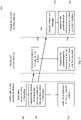
- FIG. 7 is depicted as another swim lane diagram.
- the controlling AP device 102 determines synchronization information at step 702, in the same manner as step 602.
- the processing system 330 of control device 102 instructs transmission of a synchronization control frame to device 112 at a first address.
- the AP 112 receives the synchronization data and instructs transmission of a frame 113 to a third address (corresponding to non-AP STA 114), according to timing, frequency and phase parameters based on the synchronization data.
- control device 102 instructs transmission of a frame 103 to a fourth address (corresponding to non-AP STA 104).
- AP 122 at another address also receives a synchronization control frame from the AP 112, at step 724 and instructs transmission of a frame 123 to a further address (a sixth address, corresponding to non-AP STA 124), according to timing, frequency and phase parameters based on the synchronization data.
- Each of frames 113 and 123 are transmitted to be synchronous in time, frequency and phase with the transmission of frame 103, whereby the frames 113 and 123 arrive at non-AP STA 104 at the same, time and frequency, and with their respective subcarriers in phase, with respect to the receipt of frame 103 at non-AP STA 104.
- Embodiments of the present invention may be implemented as a system, a process, and/or a computer program product.
- the computer program product may include a computer readable storage medium (or media) having computer readable program instructions thereon for causing a processor to carry out aspects of the present invention.
- each block in the flowchart or block diagrams may represent a module, segment, or portion of instructions, which comprises one or more executable instructions for implementing the specified logical function(s).
- the functions noted in the block may occur out of the order noted in the figures.
- two blocks shown in succession may, in fact, be executed substantially concurrently, or the blocks may sometimes be executed in the reverse order, depending upon the functionality involved.
- a compound or “at least one compound” may include a plurality of compounds, including mixtures thereof.
Description
- The present invention, in some embodiments thereof, relates to a device, method and program product for use in wireless communications, more specifically in some embodiments, in one or more Wireless Local Area Networks (WLANs) in which a plurality of WLAN frames are to be respectively transmitted from different transmission addresses to different reception addresses.
- In some wireless communication environments there may be one or more WLANs, each of which, or which collectively, service two or more WLAN devices, having different addresses that receive a respective two or more WLAN frames. The WLAN frames may be transmitted by WLAN devices that are each at different addresses. However, in many environments there may be mutual interference when such transmissions overlap in time, especially in cases where the transmitting and/or receiving WLAN devices are in relatively close proximity to each other.
- Wi-Fi protocols (defined by the IEEE 802.11 suite of standards, herein referred to as 802.11) are popularly employed by many modern devices for WLAN communication. As Wi-Fi protocols are becoming used in increasingly dense environments, there has been an effort to establish flavors of the protocol, e.g. 802.11ax, that operate well in such environments. However, with transmissions being needed in increasingly dense environments, there remains a need for new ways of providing for spatial reuse.
-
US 2014/153421 A1 describes a method for optimization of branch synchronization node determination in a peer-to-peer network. -
US 20157327291 A1 describes a method for increasing reuse in wireless communications. - It is an object of the present invention to provide an apparatus, a computer program product, and a method for communicating in environments in which a plurality of WLAN frames are to be respectively transmitted from different transmission addresses to different reception addresses. The present invention is defined by the appended claims and limited by the scope of the claims. Embodiments referred to in this description and not fully falling within the scope of the appended claims are examples suitable for understanding the present invention.
- Unless otherwise defined, all technical and/or scientific terms used herein have the same meaning as commonly understood by one of ordinary skill in the art to which the invention pertains. Although methods and materials similar to those described herein can be used in the practice or testing of embodiments of the invention, exemplary methods and/or materials are described below. In case of conflict, the patent specification, including definitions, will control. In addition, the materials, methods, and examples are illustrative only and are not intended to be necessarily limiting.
- Some embodiments of the invention are herein described, by way of example only, with reference to the accompanying drawings. With specific reference now to the drawings in detail, it is stressed that the particulars shown are by way of example and for purposes of illustrative discussion of embodiments of the invention. In this regard, the description taken with the drawings makes apparent to those skilled in the art how embodiments of the invention may be practiced.
- In the drawings:
-
FIG. 1A is a conceptual diagram of an exemplary wireless communications environment having of a plurality of WLAN devices configured to operate a method in accordance with an aspect of the present invention; -
FIG. 1B depicts a frame format of an exemplary WLAN frame communicated in the method; -
FIG. 2 is a conceptual block diagram that is depicting an exemplary architecture of a device configured to operate the method; -
FIG. 3 is a conceptual block diagram of an exemplary processor that may be included in the device and is in accordance with an aspect of the invention; -
FIG. 4 depicts an exemplary communication in which synchronization data in accordance with some embodiments of the present invention is transmitted; -
FIG. 5 is depicts another exemplary communication in which synchronization data in accordance with some embodiments of the present invention is transmitted; -
FIG. 6 is a swim lane diagram depicting an exemplary method in accordance with an aspect of the present invention; and -
FIG. 7 is a swim lane diagram depicting another exemplary method in accordance with an aspect of the present invention. - The present invention, in some embodiments thereof, relates to a device, method and program product for use in wireless communications, more specifically in some embodiments, in one or more WLANs in which a plurality of WLAN frames are to be respectively transmitted from different transmission addresses to different reception addresses.
- The present inventors understand that previously in wireless local area network communications, when different devices (for example, but not necessarily) access points transmit WLAN frames addressed to different receivers, there is no synchronization in the transmissions of the WLAN frames. Each transmitting device operates the transmission independently of the other transmitting device, and this can lead to interference at any one of the receivers if they are in relatively close proximity to each other whereby the receivers receives both WLAN frames. They present inventors, however, have recognized that this mitigated can be solved by synchronizing transmission of the WLAN frames.
- Thus, in general, non-limiting terms, synchronization information is determined for each of a plurality of OFDM signals in a respective plurality of WLAN frames. The WLAN frames are respectively transmitted from different transmission addresses, for example by different access points, and respectively define different reception addresses to be processed by different receivers, for example different end-user devices. A transmitted message or messages comprising the synchronization information configures a first device to transmit a first OFDM signal of said plurality of OFDM signals synchronously with a transmission, by a second device, of a second OFDM signal of said plurality of OFDM signals.
- When the device has access to the transmission medium it sends the synchronization data to one or more other devices, including the first device, so that a the second OFDM signal, which is transmitted or received by the device, is "protected" from interference. The second OFDM signal is protected in the sense that, because of the synchronization, there can be mitigation of interference from any interfering OFDM signals transmitted from respective ones of the other devices.
- In some embodiments the transmitting devices are in a common WLAN network. However, in other embodiments, they are in different WLAN networks. In any either case, in some embodiments the transmission of the synchronization data is a wireless transmission, such as in WLAN frame.
- One potential advantageous of having synchronous transmission of the first and second OFDM signals, most beneficially where synchronization is in time, frequency and phase, is that synchronous transmission can potentially reduce interference between the two OFDM signals and therefore improve capacity for spatial reuse. This is because when a given one of the receivers receives both OFDM signals (i.e. the OFDM signal addressed to that receiver, and the OFDM addressed to the other receiver), signal components in the same frequencies may be summed and compensated for by the receiving device. For example, Minimum Variance Distortion-less Response (MVDR) can be used to estimate the spatial properties (direction) of the interferer (the transmitting device the transmitting the interfering signal) and to place a null on the signal coming from that direction.
- Further, in the case of multiple interfering signals, the components of the interfering signal may be summed and treated as coming from and be treated as having come from a single spatial direction, thus making the null compensation much easier to implement, as only one direction needs to be nulled. Thus, while interference mitigation may be implemented in the case of a single interferer, there is a benefit is even more pronounced in the case of multiple interferers.
- Referring now to the drawings,
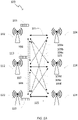
FIG. 1A illustrates an exemplarywireless communications environment 100, having of a plurality ofWLAN devices FIG. 1A , each of theWLAN devices WLAN devices -
APs respective WLAN frames WLAN frames non-AP STAs corresponding path FIG, 1 . Each of theWLAN devices WLAN frames APs other APs paths FIG. 1A . - Transmission of the WLAN frames 103, 113, 123 follow not only the intended
paths FIG.1 , to the non-APs 104, 114, 124 for which the WLAN frame is not addressed, and therefore has a potential to interfere with the WLAN frame intended for the non-AP STA. For example, some embodiments described herein address the problem thatWLAN frame 113 and/or 123 may arrive atnon-AP STA 104, even though they are not addressed to it, and their arrival may interfere with the reception of theframe 103 that is addressed tonon-AP STA 104. Each of the non-AP STAs has N antennas operates an MVDR to estimate the direction of the path to interferer APs and place a null on signals coming from that direction. However, the transmissions of the WLAN frames 103, 113, 123 are synchronized, and this enables each receiver (non-AP STA), equipped with N antennas, to create up to N-1 nulls to thereby mitigate N-1 interferers. Such an MVDR technique is known in the art for mitigating multi-path interference from a single AP, whereby the multi-path signals can be mitigated provided they each arrive at the receiver within a cyclic prefix of an OFDM signal in the WLAN frame. However, the some embodiments of the present invention synchronize WLAN transmissions from different APs so that the OFDM signals of respective interfering WLAN frames arrive within the cyclic prefix, and can this be mitigated using the same MVDR processing. - An exemplary
WLAN frame format 150 that may be used for each of WLAN frames 103, 113. 123 to synchronize each of the WLAN frames in accordance with embodiments of the present invention is illustrated in FIG. IB. In this example, the frame format includes anOFDM signal 152 comprised ofmultiple OFDM symbols 154. In the example illustrated inFIG. 1B , all of the OFDM symbols are marked as being data symbols, but in other embodiments an part of the OFDM signal, comprised of one or more of the OFDM symbols, is a part of the preamble. Each of the OFDM symbols have acommon duration 156, and are separated by acyclic prefix 155, each cyclic prefix having the same guard interval length (cyclic prefix duration) 18. In addition to including an OFDM signal, each of the WLAN frames is fronted by aWLAN preamble 160 have apreamble length 162, which may for example, be or include a WLAN legacy pre-amble that consists of Wi-Fi fields L-STF (legacy short training field), L-LTF (legacy long training field) and L-SIG (legacy signal field). - An exemplary architecture of a
device 200 for performing an embodiment of one or more aspects of the present invention is illustrated inFIG. 2 . The illustrated architecture ofdevice 200 can be used for either or both ofnode devices exemplary device 200, and principal connections between those components, to aid a person skilled in the art in performing the invention. Components and connections that are not included in the illustration may therefore nonetheless be understood to be present by the person skilled in the art. - As has been discussed, the
device 200 may include any necessary computer hardware that would be understood by the person skilled in the art to needed to perform the functions of the above listed any other possible types of computing nodes. In the illustrated embodiment, thedevice 200 has aprocessing system 204 having one or more processors / execution devices. Theprocessing system 204 communicates data with at least one computer readable storage medium in the form ofmemory 207, via acommunication bus 209. Thememory 207 has asystem memory 208, avolatile memory 210 and a tangible,non-transient memory 212. The system memory may have a read only memory (ROM) that stores a basic input/output system (BIOS). The volatile memory may have a random access memory (RAM), such as dynamic random access memory (DRAM). Thenon-transient memory 212 may have a hard disk drive(s), a solid state drive(s), and/or a flash memory device(s) and the like, and may store an operating system (e.g. Microsoft Windows, Apple OSX, Unix, and Linux) and/or other program products for running for operatingdevice 200. The computer readable storage medium for providing thenon-transient memory 212 may be, for example, but is not limited to, an electronic storage device, a magnetic storage device, an optical storage device, an electromagnetic storage device, a semiconductor storage device, or any suitable combination of the foregoing. - The
processing system 204 includes a microprocessor 206 that performs tasks by executing software in the form of instructions and data stored on, and read from, the system, volatile, and/ornon-transitory memory device 200, stored in thenon-transient memory 212 or an external data storage device accessed by the computer processing system 202 via an I/O interface 214. In some embodiments, the software may be provided to computer processing system 202 via a wired or wireless communication over acommunications interface 218, which provides a network interface. Thus as will be appreciated, computer readable program instructions described herein may be downloaded to respective computing/processing devices from a computer readable storage medium or to an external computer or external storage device via a network, for example, a wireless local area network (e.g. Wi-Fi), a wide area network (e.g. the Internet), and/or a cellular network, e.g. Long-Term Evolution (LTE). Thecommunications interface 218, in any case has a WLAN communications interface (such as WLAN transceiver), and may have additional communications connections, including but not limited to, BlueTooth, ZigBee, and 3G etc. Each of the communications connections may be via a transceiverfront end 220 that drives antenna module has a series of antennas for providing beamforming and/or MVDR nulling. - The transceiver
front end 220 includes analog components and mixed analog and digital signal components. The mixed analog and signal components include a digital to analog converter (DAC) 222 that generates RF signals from one or more instructions from theprocessing system 204. In some embodiments, the one or more instructions include one or more binary data streams to be converted to an analog signal by theDAC 222. Themicrocontroller 240 may, in some embodiments (not shown), also include one or more control signals to further instruct the transceiverfront end 220, e.g. to be control the DAC, theduplexer 228 or an amplifier module (not shown). For example the FDD support ofduplexer 228 may be switched off when FDD is not in operation. - The mixed analog and signal components include an analog to digital converter (ADC) 224 for converting received RF signals to digital form which are then processed by the
processing system 204. The processing of the analog signal components are handled by an RF front end that includes aninterference reduction module 226 that acts to minimize interference between the outbound signal from the DAC and the inbound signal to the ADC and aduplexer 228 for simultaneously sending and receiving signals to theantenna module 221 to support FDD on anantenna module 221 that is commonly employed for both transmitting and receiving RF signals. In other embodiments there is noduplexer 228 and FDD is supported by having different antenna modules can be used for transmitting and receiving signals. -
Processing system 204 also includes aprocessor 230 that may be adapted to perform an embodiment of one or more aspects of the present invention. For example, in some embodiments theprocessor 230 is adapted to perform a method of the some embodiments of the present invention, for example by executing one or more tasks. In some embodiments, the tasks are provided in instructions stored in thenon-transient memory 212. Thus, in some embodiments, theprocessor 230 may comprise electronic circuitry including, for example, programmable logic circuitry, field-programmable gate arrays (FPGA), or programmable logic arrays (PLA) that execute a computer readable program instructions by utilizing state information of the computer readable program instructions to personalize the electronic circuitry, in order to perform one or more aspects of the present invention. - The
processor 230 generates digital instructions that it forwards to the transceiver front end, and theprocessor 230 receives the digital signal generated received by the transceiverfront end 220. It is therefore convenient to herein refer to theprocessor 230 to as a transceiver back-end. In the context of the Open Systems Interconnection (OSI) of a telecommunication system, the processor operates digital aspects of the physical layer (PHY) of the OSI model, via digital PHY transmitmodule 232 and PHY receivemodule 234, operates the data link layer via data link transmitmodule 236 and data link receivemodule 238. In any case, in some embodiments themicrocontroller 240 communicates with microprocessor 206 via a communications interface, such as SPI, SDIO, I2C, UART or GPIO. In some embodiments, at least a portion of the data link layer functions are performed by amicrocontroller 240. - The
processor 230 can include a RAM to enable data storage by themicrocontroller 240, the transmitlink modules 236, and the receivedata link modules 238. Non-transient memory can also be included in themicrocontroller 240 to configure the microcontroller's operation. In other embodiments theprocessor 230 adapted to perform an aspect of the present invention is an application-specific integrated circuit (ASIC) chip. - In other embodiments some or all of the functions of
processor 230 may be integrated into microprocessor 206. It will therefore be appreciated by a person skilled in the art that theprocessor 230 may be a processing component of a larger processing chip / integrated circuit, or may be a stand-alone processing chip. Further, as will be appreciated by a person skilled in the art that theprocessor 230 may alternatively be distributed amongst multiple chips. -
FIG. 3 illustrates an exemplary embodiment of aprocessor 330, which is an exemplary embodiment ofprocessor 230 in which theprocessor 230 is adapted as the back-end (i.e. digital end) of a WLAN transceiver. Alternatively, the features ofprocessor 330 may be incorporated into theprocessor 230 to provide theprocessor 230 with its WLAN functionality. -
Features processor 230 respectively correspond tofeatures processor 330. However, inprocessor 330 more specifically has a MAC transmitmodule 336 and MAC receivemodule 338 in place of the data link layer transmit and receive modules, respectively. A logical link control sublayer of the data link layer is included inmicrocontroller 330. The digital components of the PHY layer are provided by IEEE 802.11 compliant transmit and receivecomponents - In some embodiments, the MAC transmit
module 336 generates a MAC layer protocol data unit (MDPU) that includes an aggregated MAC layer data unit in the form of aggregated MAC service data unit (A-MSDU), the A-MSDU having been generated in and received from the logical link control sublayer. The MAC transmit module forwards the MPDU to the PHY transmitcomponent 332. - In other embodiments, the MAC transmit
module 336 generates an aggregated MAC layer data unit in the form of an aggregated MAC protocol data unit (A-MPDU), which the MAC transmitmodule 336 then forwards to the digital PHY transmitcomponent 332. Optionally, the A-MPDU can include one or more A-MSDUs. - The aggregated MAC layer data unit may be an A-MSDU or A-MPDU (including, but not limited to, A-MPDUs that incorporate an A-MSDU), but in exemplary embodiments described hereinafter is an A-MPDU.
- The A-MPDU), or optionally a non-aggregated MAC protocol data unit (MPDU), is provided to the digital PHY transmit
component 332. For exemplary embodiments illustrated hereinafter the PHY transmit component may be any OFDM based PHY component, and thus may be an IEEE 802.11 PHY component, such a PHY component of 802.11a, 802.11g, 802.1 In, 802.11ac, 802.11ax or future 802.11 technologies. - The digital PHY transmit
component 332 receives a relevant data unit from the MAC transmitmodule 336, the received data unit being a PHY service data unit (PSDU). From the PSDU, the digital PHY transmitcomponent 332 generates a PHY protocol data unit (PPDU) that includes a data component generated by a PHY data generator and a header generated by a PHY preamble generator. - A modulation and coding scheme is applied to each of a plurality of OFDM subcarriers having a defined bandwidth and being spread at difference frequencies that collectively span a total bandwidth of the PHY layer.
- The total number of OFDM tones/subcarriers may, for example, be selected to be a set of 26, 52, 106, 242, 484 or 996 OFDM tones/subcarriers. In some embodiments, each subcarrier has a bandwidth of 78.125 kHz. In some embodiments, all of the subcarriers are be used to transmit to an OFDM signal in a given WLAN frame. In other embodiments only a portion of the subcarriers are used to transmit the OFDM signal, such a portion being known in that art a resource unit (RU).
- The PHY data generator converts the coded and translated aggregated MAC layer data unit to the time domain by calculating an inverse Fast Fourier Transform (IFFT). The calculated signal is forwarded as a payload, with a PHY preamble, to the transceiver
front end 220, which converts the calculated signal to an analog signal and drives transmission of the analog signal, as a frame, fromantenna 221. - The PHY preamble is generated by the PHY preamble generator. In some embodiments, the preamble (PA) of the MPDU/A-MPDU payload is fronted by a legacy WLAN preamble, e.g. a Wi-Fi legacy preamble consisting of L-STF, L-LTF and L-SIG, with the L-SIG field defining a transmission time (duration) of the frame, and includes any protocol-dependent fields needed by the protocol.
- Upon receiving a frame from another device, on
antenna 221, the transceiverfront end 220 filters the signal, performs interference reduction, including MVDR based interference reduction (or another interference reduction scheme) viamodule 226 and converts the signal to digital form viaADC 224 for processing byprocessor 330. The 802.11 digitalPHY receiving component 334 performs an FFT, demodulates and decodes the received data, and performs forward error correction, before finally forwarding the data to theMAC receiving module 338 for higher level processing. In some embodiments theprocessor 330 operates according to IEEE 802.11ax, which may be as defined in IEEE standard Draft P802.11ax-D2.0, October 2017,. In accordance with IEEE 802.11ax, if a certain type of frame, called a "trigger frame" is received, themicrocontroller 340 will instruct transmission of a frame, based on parameters in the trigger frame. In other embodiments, the trigger frame may be in accordance with the trigger frame defined inUS patent application publication 2016/0165589 A1 (US'589), . In other embodiments, other trigger frame implementations may be employed. - In some embodiments the
device 200 is for each ofAPs - The
non-AP STAs - In addition to the functions described above, the
device 200 may have a variety of other hardware elements. For example, in some embodiments it may be any network-enabled computing device (e.g. a laptop, router etc., as has been described). For example I/O interface 214 may include one or more of a speaker, microphone, keypad, display/touchscreen etc., which may be integrally incorporated into the device. Additionally the device may include aperipherals interface 215 to connect with one or more ancillary devices such as a mouse, keyboard, monitor, scanner, projector, digital camera etc. An environmental sensing system 217 may also be included to provide for example, temperature sensing, or a global positioning system or to measure any other condition of the device's environment. The device may also include an internal power source 219, such as a battery, which may be a rechargeable battery. - During operation a first one of APs (e.g. AP 112) and a second one of the APs (e.g. AP 122) receive synchronize data for synchronizing
frames frames non-AP STA 104,e.g. frame 103. The synchronization data is transmitted in a frame addressed to bothAPs paths APs AP -
FIG. 4 illustrates an example of acommunication 400 in which the synchronization data may be transmitted toAPs frames portion 408 of transmission opportunity period (TxOP) 400, such as a TxOP as defined in 802.11ax. Each of the frames are spaced by a short interframe spacing (SIFS) defined by the WLAN protocol with which it is communicated. The communication data is included in asynchronization control frame 402. The synchronization data provides information toAPs uplink frame 406 that is to be transmitted bynon-AP STA 104. In some embodiments, an SIFS after transmitting the synchronization control frame theAP 102 transmits adownlink frame 103 with which frames 113 and 123 are to be synchronized. However, in other embodiments, theAP 102 does not transmit a frame to which transmission offrames AP 102 receives a frame transmission to which transmission offrames - In the embodiment shown in
FIG. 4 , an SIFS after transmitting the synchronization control frame theAP 102 transmits a trigger frame tonon-AP STA 104 to configure the non-AP STA to transmit theuplink frame 406 at a specific time corresponding with timing information included in the synchronization data, and using OFDM symbols of a specific duration and separated by a specific cyclic prefix. Theuplink frame 406 may thus have a format matching the format ofWLAN frame 150. Thus, the OFDM signal of the uplink WLAN frame commences after a preamble portion of the frame. Although thenon-AP STA 104 is transmitting rather than receiving, when frames 113 and 123 are being transmitted, the synchronization of theframes non-AP STA 104. Also, when theuplink frame 406 arrives atAP 102, there is potential forframes frame 406 at theAP 102. Thus the synchronization may additionally or alternatively be for interference mitigation atAP 102. In yet other embodiments the trigger frame and synchronization data is addressed to each ofnon-AP STAs non-AP STAs uplink frame 406. The phase synchronization of the transmissions can be configured to produce zero phase difference at the transmitter or receiver of theframe 406, but in some embodiments is configured to produce zero phase difference at the receiver of theuplink frame 406, i.e. atAP 102. - In another embodiment of the invention illustrated in
FIG. 5 , rather than having a synchronization control frame,synchronization data 502 may joined to an end (or other part) of atrigger frame 504 to form a synchronization andtrigger frame 505. In such an embodiment, anuplink frame 506 follows the synchronization andtrigger frame 505 by an SIFS. - For WLAN protocols in which the OFDM symbol duration and cyclic prefix duration are each configurable, the preamble duration, OFDM symbol duration and cyclic prefix duration are included in the synchronization data. These durations may be defined in the synchronization data in any unit of measurement(s) from which time may be extrapolated, for example, as an actual amount of time, or as a number of bits at a known bit rate. The synchronization data may also include a size of the WLAN frame.
- In some implementations, however, the preamble duration, OFDM symbol duration, and/or cyclic prefix duration may be fixed and the same for all protocols used by the APs to communication with their corresponding non-AP STAs. For such implementations, the fixed one or more of the preamble duration, OFDM symbol duration and cyclic prefix duration need not be included in the synchronization control frame.
- A device addressed by the synchronization data determines synchronization parameters from the synchronization data. The synchronization parameters include transmission timing details. In embodiments where frequency, phase, and/or frame format details are variable, then any such variable parameters are also derived from the synchronization data. The following description assumes that each of these parameters is derived from the synchronization data.
- The synchronization data includes transmission timing that indicates the common time with an error sufficiently small to synchronize the transmission of the OFDM signals within a cyclic prefix used by each of the OFDM signals. Ideally, the error is negligible (e.g. in some embodiment less than 10%; in some embodiment less than 5%; in some embodiments less than 1%; in some embodiments less than 0.5%) compared with the cyclic prefix so that it can maintain full effectiveness in its usual function, which is to minimize inter-symbol interference arising from multi-path signals from a given source.
- The transmission timing is firstly determined by the
AP 102 before it is transmitted. The transmission timing can be determined by scheduling commencement of transmitting each of the plurality of OFDM signals as a relative time with respect to a transmission trigger. The transmission timing comprises a transmission trigger, which for example can be a part of certain field or signal in a synchronization control frame. However, the time of the trigger event (the appearance of the trigger) is perceived differently by thedevice 102 that transmits the trigger and thedevices device 102, and (ii) the time associated with the transmission trigger, as perceived by thedevice 112. If the time will be perceived differently bydevice 122, then the timing offset defines that difference, as well. While the trigger event may be a common marker for each device, the nominal timing (prior to adjustment by the timing offset) may be some defined delay after the trigger event. For example, the device may send a trigger and identify (or it may be predefined) that thedevice 112 is to transmit its next frame 10 milliseconds after receiving the trigger, but each ofdevices device 102, at the location of the desired signal's transmitter or receiver (whichever is location at which the interference is to be mitigated). - In alternative embodiments, rather than providing relative timing as described above, the synchronization data includes an actual time for commencing the transmitting each of the plurality of OFDM signals. An indication of the common time is provided and comprises a reference to the actual time with respect to a remote clock, such as a GPS clock. Optionally offset timing is also included in this case too, so that each device can correct for differences in interpretation of the time from the remote clock. Although depending on the implementation there may be no need for correction.
- Using the synchronization data, OFDM subcarriers of the OFDM signals are also synchronized in a frequency domain. This can be achieved using any of a plurality of known techniques known by the person skilled in the art, whereby information is provided to the
first device 112 so that the first device can adjust the frequencies of the OFDM subcarriers of the first ODFM signal to match the corresponding frequencies of the OFDM subcarriers of the second OFDM signal. Thus, the synchronization data may, for example, include a parameter that defines a previously determined difference in the respective oscillator frequencies from which the OFDM subcarriers are generated at thefirst device 112 andsecond device - Using the synchronization data, the OFDM symbols of the first OFDM signal are synchronized in phase with OFDM symbols of the second OFDM signal. The transmission of the signals is phase synchronized so that there is a zero phase angle between the corresponding OFDM subcarriers that carrier the OFDM symbols in the first and second OFDM signals, respectively, at a selected one of the transmitter or receiver of the second OFDM signal. The phase synchronization is based on phase synchronization data included in the synchronization data transmitted to the
first device 112. The phase synchronization data may for example, represent a previously determined phase offset, using any one of a plurality of known techniques for determining phase difference between two transmitters and a receiver. For example a the phase difference can be determined from known joint transmission techniques in which the multiple sources transmit the same data to be received at the single receiver which require synchronization, e.g. using Coordinated Multi-Point (CoMP) technology. In another example, the phase synchronization data represents information which may be used by thefirst device 112, in conjunction with other data, to determine the phase difference using a known technique. - The synchronization data also includes format data identifying a duration of a preamble, a duration of each OFDM symbol in the OFDM signal, and duration of a cyclic prefix, each of which are common to the WLAN frames that are to be synchronized. A WLAN device that receives this frame format data as part of synchronization data will format the next WLAN frame according to the frame format data, thus synchronization at the start of the WLAN frame is maintained for entirety of the WLAN frame. Further the duration of the WLAN frames can also be set in the synchronization data, so that the synchronization can be maintained for any subsequent frames that occur a short interframe spacing after a first synchronized frame.
- An
exemplary method 600 for synchronizing WLAN frames in accordance with one or more embodiments of the present inventionFIG. 6 is depicted as a swim lane diagram. Atstep 602,processor 330 ofcontrol device 102 determines synchronization information (data), as described above, for a future frame transmission. Atstep 604 theprocessor 330 ofcontrol device 102 instructs transmission of the synchronization information, e.g. using a synchronization control frame, or trigger and synchronization frame, as previously described herein. However, it for the purpose of explaining theFIG. 6 it will be assumed that the synchronization data is included in asynchronization control frame 402. Attime step 606, a first synchronization control frame is transmitted at time. The synchronization control frame arrives atAP 112, at a first address, attime 608. - At
step 609 theprocessor 330 ofcontrol device 102 instructs transmission of atrigger frame 404, which is transmitted bycontrol device 102 at time 610 and arrives atnon-AP STA 104, at a second address, attime 612. - Upon receiving synchronization control frame, at
step 614, theAP 112 determines timing, frequency and phase parameters for synchronous transmission of its next frame transmission, which is to be addressed tonon-AP STA 114 at a third address. - Upon receiving the trigger frame, at
step 624, atstep 626 the processor ofnon-AP STA 104 instructs transmission, from thenon-AP STA 104, of anuplink frame 406 to thecontrol device 102, the uplink transmission commencing a short interframe spacing after complete receipt of the trigger frame. - Meanwhile, at
step 616 the processor ofAP 112 instructs its transceiver front-end to transmit theframe 113 on subcarriers at frequencies dependent on the frequency parameters at a time depending on the timing parameter(s) to be at the same time the transmission of the uplink frame by thenon-AP STA 104. However, rather than the respective transmissions being at precisely the same time of commencement of the transmission of theframe 113 is offset according to the phase parameters such that an OFDM signal inframe 113, although addressed tonon-AP STA 114 and not controldevice 102, will nonetheless arrive at thecontrol device 102 at the same time as an OFDM signal inframe 406, with the respective OFDM signals being in phase atcontrol device 102. - In other embodiments (not shown), rather than sending a synchronization control frame to
AP 112 atstep 606 and a trigger frame tonon-AP STA 104, the control device addresses and transmits a trigger andsynchronization frame 506 tonon-AP STAs non-AP STA 104 behaves in the same way as the embodiment in which is receives a trigger frame. However,non-AP STA 114 is configured by the trigger andsynchronization frame 506 to transmit an uplink frame toAP 112 synchronously with the transmission of anuplink frame 506 bynon-AP STA 104. - Another
exemplary method 700 for synchronizing WLAN frames in accordance with some embodiments of the present inventionFIG. 7 is depicted as another swim lane diagram. In this example thecontrolling AP device 102 determines synchronization information atstep 702, in the same manner asstep 602. Atstep 704, theprocessing system 330 ofcontrol device 102 instructs transmission of a synchronization control frame todevice 112 at a first address. Insteps AP 112 receives the synchronization data and instructs transmission of aframe 113 to a third address (corresponding to non-AP STA 114), according to timing, frequency and phase parameters based on the synchronization data. Atstep 718control device 102 instructs transmission of aframe 103 to a fourth address (corresponding to non-AP STA 104). Like in the case of the example inFIG. 7 ,AP 122 at another address (a fifth address) also receives a synchronization control frame from theAP 112, atstep 724 and instructs transmission of aframe 123 to a further address (a sixth address, corresponding to non-AP STA 124), according to timing, frequency and phase parameters based on the synchronization data. Each offrames frame 103, whereby theframes non-AP STA 104 at the same, time and frequency, and with their respective subcarriers in phase, with respect to the receipt offrame 103 atnon-AP STA 104. - It is to be understood that the invention is not necessarily limited in its application to the details of construction and the arrangement of the components and/or methods set forth in the above description and/or illustrated in the drawings and/or the Examples. The invention is capable of other embodiments or of being practiced or carried out in various ways.
- Embodiments of the present invention may be implemented as a system, a process, and/or a computer program product. The computer program product may include a computer readable storage medium (or media) having computer readable program instructions thereon for causing a processor to carry out aspects of the present invention.
- Aspects of the present invention are described herein with reference to flowchart illustrations and/or block diagrams of methods, apparatus (systems), and computer program products according to embodiments of the invention. It will be understood that each block of the flowchart illustrations and/or block diagrams, and combinations of blocks in the flowchart illustrations and/or block diagrams, can be implemented by computer readable program instructions.
- The flowchart and block diagrams in the Figures illustrate the architecture, functionality, and operation of possible implementations of systems, methods, and computer program products according to various embodiments of the present invention. In this regard, each block in the flowchart or block diagrams may represent a module, segment, or portion of instructions, which comprises one or more executable instructions for implementing the specified logical function(s). In some alternative implementations, the functions noted in the block may occur out of the order noted in the figures. For example, two blocks shown in succession may, in fact, be executed substantially concurrently, or the blocks may sometimes be executed in the reverse order, depending upon the functionality involved. It will also be noted that each block of the block diagrams and/or flowchart illustration, and combinations of blocks in the block diagrams and/or flowchart illustration, can be implemented by special purpose hardware-based systems that perform the specified functions or acts or carry out combinations of special purpose hardware and computer instructions.
- Other systems, methods, features, and advantages of the present disclosure will be or become apparent to one with skill in the art upon examination of the following drawings and detailed description. It is intended that all such additional systems, methods, features, and advantages be included within this description, be within the scope of the present disclosure, and be protected by the accompanying claims.
- The descriptions of the various embodiments of the present invention have been presented for purposes of illustration, but are not intended to be exhaustive or limited to the embodiments disclosed. Many modifications and variations will be apparent to those of ordinary skill in the art without departing from the scope of the described embodiments. The terminology used herein was chosen to best explain the principles of the embodiments, the practical application or technical improvement over technologies found in the marketplace, or to enable others of ordinary skill in the art to understand the embodiments disclosed herein.
- The terms "comprises", "comprising", "includes", "including", "having" and their conjugates mean "including but not limited to". This term encompasses the terms "consisting of" and "consisting essentially of".
- As used herein, the singular form "a", "an" and "the" include plural references unless the context clearly dictates otherwise. For example, the term "a compound" or "at least one compound" may include a plurality of compounds, including mixtures thereof.
- The word "exemplary" is used herein to mean "serving as an example, instance or illustration". Any embodiment described as "exemplary" is not necessarily to be construed as preferred or advantageous over other embodiments and/or to exclude the incorporation of features from other embodiments.
- The word "optionally" is used herein to mean "is provided in some embodiments and not provided in other embodiments". Any particular embodiment of the invention may include a plurality of "optional" features unless such features conflict.
- It is appreciated that certain features of the invention, which are, for clarity, described in the context of separate embodiments, may also be provided in combination in a single embodiment. Conversely, various features of the invention, which are, for brevity, described in the context of a single embodiment, may also be provided separately or in any suitable subcombination or as suitable in any other described embodiment of the invention. Certain features described in the context of various embodiments are not to be considered essential features of those embodiments, unless the embodiment is inoperative without those elements.
Claims (13)
- A device (102) comprising:
at least one processor adapted (330) to:determine synchronization information for each of a plurality of orthogonal frequency duplex multiplexing, OFDM, signals (152) in a respective plurality of wireless local area network, WLAN, frames (103, 113, 123), the WLAN frames respectively being transmitted from different transmission addresses and respectively defining different reception addresses to be processed by different receivers (102, 112, 122); andinstruct transmission of at least one message (402, 505) comprising the synchronization information;wherein the at least one message configures a first device (112) to transmit a first OFDM signal (113) of said plurality of OFDM signals synchronously with a transmission, by a second device (102 or 122), of a second OFDM signal (103 or 123) of said plurality of OFDM signals;wherein OFDM sub carriers of the first OFDM signal are synchronized, in a frequency domain, to OFDM subcarriers of the second OFDM signal; and/orwherein OFDM symbols of the first OFDM signal (113) are synchronized in phase with OFDM symbols of the second OFDM signal (103 or 123). - A device according to claim 1, wherein the synchronization information (502) comprises transmission timing for transmitting of each of the OFDM signals at a common time.
- A device according to claim 2, wherein the transmission timing indicates the common time with an error sufficiently small to synchronize the transmission of the OFDM signals within a cyclic prefix (155) used by each of the OFDM signals.
- The device according to claim 2 or 3, wherein determining the transmission timing comprises at least one of:(i) scheduling commencement of transmitting each of the plurality of OFDM signals as a relative time with respect to a transmission trigger, wherein the transmission timing comprises:the transmission trigger; anda timing offset representing a difference between (i) a time associated with the transmission trigger, as perceived by the first device, and (ii) the time associated with the transmission trigger, as perceived by the second device; and(ii) scheduling an actual time for commencing the transmitting each of the plurality of OFDM signals, wherein the indication of the common time comprises a reference to the actual time with respect to a remote clock.
- A device according to any one of claims 1 to 4, wherein the synchronization information indicates a cyclic prefix (155) duration (156) and an OFDM symbol duration (158), to configure each of the OFDM signals to have OFDM symbols (154) having the OFDM symbol duration (156) and being spaced by the cyclic prefix (155).
- The device according to any one of claims 1 to 5, wherein the at least one processor is further adapted to instruct said transmission of the second OFDM signal, and the synchronization information is included in at least one WLAN frame (402, 505) that precedes the plurality of WLAN frames (408) by at least a short inter-frame spacing, the short inter-frame spacing being defined by a WLAN protocol for the WLAN transmission, the at least one frame comprising at least one of:a synchronization control frame (402); anda trigger frame that configures (504) a WLAN transceiver to transmit a frame to the device, the transmission of the frame commencing at the common time.
- The device according to any one of claims 1 to 6, wherein the at least one message further comprises format data identifying a duration (162) of a preamble (160) common to each of the WLAN frames.
- The device according to any one of the preceding claims, wherein the at least one message is addressed to the first device (112) and third device (122), the third device being at a fifth address, wherein the at least one message configures the third device (122) to transmit a third OFDM signal (123), to a sixth address (124), synchronously with the transmission, by a second device (102), of the second OFDM signal (103).
- A device (112) comprising:
at least one processor (330) adapted to:
receive at least one message (402) comprising:synchronization information for each of a plurality of orthogonal frequency duplex multiplexing, OFDM, signals in a respective plurality of wireless local area network, WLAN, frames (103, 113, 123), the WLAN frames respectively being transmitted from different transmission addresses and respectively defining different reception addresses to be processed by different receivers (104, 114, 124); andbased on the synchronization information, instruct transmission of a first OFDM signal of said plurality of OFDM signals synchronously with a transmission, by a second device (102 or 122), of a second OFDM signal of said plurality of OFDM signals;wherein OFDM sub carriers of the first OFDM signal are synchronized, in a frequency domain, to OFDM subcarriers of the second OFDM signal; and/orwherein OFDM symbols of the first OFDM signal (113) are synchronized in phase with OFDM symbols of the second OFDM signal (103 or 123). - A method (600, 700) comprising:determining synchronization information for each of a plurality of orthogonal frequency duplex multiplexing, OFDM, signals in a respective plurality of wireless local area network, WLAN, frames (103, 113, 123), the WLAN frames respectively being transmitted from different transmission addresses and respectively defining different reception addresses to be processed by different receivers (104, 114, 124); andinstructing transmission of at least one message (402, 505) comprising the synchronization information;wherein the at least one message configures a first device (112) to transmit a first OFDM signal of said plurality of OFDM signals synchronously with a transmission, by a second device (102 or 122), of a second OFDM signal of said plurality of OFDM signals;wherein OFDM sub carriers of the first OFDM signal are synchronized, in a frequency domain, to OFDM subcarriers of the second OFDM signal; and/orwherein OFDM symbols of the first OFDM signal (113) are synchronized in phase with OFDM symbols of the second OFDM signal (103 or 123).
- A method according to claim 10, wherein:the synchronization information comprises transmission timing for transmitting of each of the OFDM signals at a common time;OFDM subcarriers of the first OFDM signal are synchronized, in a frequency domain, to OFDM subcarriers of the second OFDM signal; andOFDM symbols of the first OFDM signal are synchronized in phase with OFDM symbols of the second OFDM signal.
- A method (600, 700) comprising:
receiving (614, 714) at least one message (402) comprising:synchronization information for each of a plurality of orthogonal frequency duplex multiplexing, OFDM, signals in a respective plurality of wireless local area network, WLAN, frames, the WLAN frames (103, 113, 123) respectively being transmitted from different transmission addresses and respectively defining different reception addresses to be processed by different receivers (104, 114, 124); andbased on the synchronization information, instructing transmission of a first OFDM signal of said plurality of OFDM signals synchronously with a transmission, by a second device (102 or 122), of a second OFDM signal of said plurality of OFDM signals;wherein OFDM subcarriers of the first OFDM signal are synchronized, in a frequency domain, to OFDM subcarriers of the second OFDM signal; and/orwherein OFDM symbols of the first OFDM signal (113) are synchronized in phase with OFDM symbols of the second OFDM signal (103 or 123). - A computer program with a program code for performing a method according to any one of claims 10 to 12, when the computer program is executed by at least one processor (330).
Priority Applications (1)
| Application Number | Priority Date | Filing Date | Title |
|---|---|---|---|
| PL17825860.4T PL3689051T3 (en) | 2017-12-22 | 2017-12-22 | Device and method for use in wireless communications |
Applications Claiming Priority (1)
| Application Number | Priority Date | Filing Date | Title |
|---|---|---|---|
| PCT/EP2017/084290 WO2019120558A1 (en) | 2017-12-22 | 2017-12-22 | Device and method for use in wireless communications |
Publications (2)
| Publication Number | Publication Date |
|---|---|
| EP3689051A1 EP3689051A1 (en) | 2020-08-05 |
| EP3689051B1 true EP3689051B1 (en) | 2022-07-27 |
Family
ID=60937745
Family Applications (1)
| Application Number | Title | Priority Date | Filing Date |
|---|---|---|---|
| EP17825860.4A Active EP3689051B1 (en) | 2017-12-22 | 2017-12-22 | Device and method for use in wireless communications |
Country Status (4)
| Country | Link |
|---|---|
| EP (1) | EP3689051B1 (en) |
| CN (2) | CN111480372B (en) |
| PL (1) | PL3689051T3 (en) |
| WO (1) | WO2019120558A1 (en) |
Families Citing this family (1)
| Publication number | Priority date | Publication date | Assignee | Title |
|---|---|---|---|---|
| CN114760640B (en) * | 2021-01-08 | 2023-09-08 | 华为技术有限公司 | Wireless local area network sensing method and device |
Family Cites Families (12)
| Publication number | Priority date | Publication date | Assignee | Title |
|---|---|---|---|---|
| FR2939005A1 (en) * | 2008-11-21 | 2010-05-28 | Thomson Licensing | DATA TRANSMITTING METHOD AND CORRESPONDING RECEIVING METHOD |
| US9408166B2 (en) * | 2011-09-30 | 2016-08-02 | Intel Corporation | Mitigating overlapping basic service set interference in smart grid networks |
| US9301158B2 (en) * | 2012-11-30 | 2016-03-29 | Qualcomm Incorporated | Systems and methods for optimization of branch synchronization node determination in a peer-to-peer network |
| US10477376B2 (en) * | 2013-01-11 | 2019-11-12 | Qualcomm Incorporated | Systems and methods for formatting frames in neighborhood aware networks |
| WO2014179713A1 (en) * | 2013-05-03 | 2014-11-06 | Interdigital Patent Holdings, Inc. | Systems and methods for fractional carrier sense multiple access with collision avoidance (csma/ca) for wlans |
| US20150327291A1 (en) * | 2014-05-08 | 2015-11-12 | Qualcomm Incorporated | Systems, methods, and apparatus for increasing reuse in wireless communications |
| EP3207646B1 (en) * | 2014-10-17 | 2021-07-14 | Cisco Technology, Inc. | Simultaneous communication with multiple wireless communication devices |
| WO2016090372A1 (en) | 2014-12-05 | 2016-06-09 | Marvell Semiconductor, Inc. | Trigger frame format for orthogonal frequency division multiple access (ofdma) communication |
| US20170019863A1 (en) * | 2015-07-14 | 2017-01-19 | Intel IP Corporation | Uplink power control for user devices at varying distances from an access point |
| US10687288B2 (en) * | 2016-02-02 | 2020-06-16 | Qualcomm Incorporated | Synchronization across transmitting nodes using shared radio frequency spectrum |
| CN109076498B (en) * | 2016-04-29 | 2020-03-10 | 华为技术有限公司 | Method for forming central access point AP cluster and access point |
| CN106254147B (en) * | 2016-09-08 | 2019-06-28 | 珠海全志科技股份有限公司 | It is a kind of for the configuration method of Wi-Fi network, internet-of-things terminal and control terminal |
-
2017
- 2017-12-22 WO PCT/EP2017/084290 patent/WO2019120558A1/en unknown
- 2017-12-22 CN CN201780097648.7A patent/CN111480372B/en active Active
- 2017-12-22 CN CN202111598313.8A patent/CN114423072A/en active Pending
- 2017-12-22 PL PL17825860.4T patent/PL3689051T3/en unknown
- 2017-12-22 EP EP17825860.4A patent/EP3689051B1/en active Active
Also Published As
| Publication number | Publication date |
|---|---|
| PL3689051T3 (en) | 2022-09-12 |
| CN111480372B (en) | 2021-12-28 |
| CN111480372A (en) | 2020-07-31 |
| WO2019120558A1 (en) | 2019-06-27 |
| CN114423072A (en) | 2022-04-29 |
| EP3689051A1 (en) | 2020-08-05 |
Similar Documents
| Publication | Publication Date | Title |
|---|---|---|
| US10771999B2 (en) | Measuring distance in wireless devices | |
| US9413581B2 (en) | System and method for synchronization for OFDMA transmission | |
| US9948367B2 (en) | Methods and apparatus for acknowledging multiple user uplink transmissions | |
| US20170079071A1 (en) | Systems, methods, and devices for enhanced ofdma random access | |
| CN110249555B (en) | Synchronization signal burst, signal design and system frame acquisition within a new radio | |
| JP2017525273A (en) | Method and apparatus for multi-user uplink control and scheduling over aggregated frames | |
| US9585095B2 (en) | Methods and devices for enhanced power save protocol | |
| JP6698523B2 (en) | Method and apparatus for wireless communication using mixed formats | |
| JP6749977B2 (en) | Response time mitigation for highly efficient WLAN | |
| US20240107537A1 (en) | Methods and apparatus for joint multi-ap transmission in wlans | |
| CN115347993A (en) | Interference reduction for reference symbols in URLLC/EMBB multiplexing | |
| TW201618481A (en) | Protection for multi-user transmissions | |
| US9681407B2 (en) | Time synchronization function rollover solution | |
| US10075226B2 (en) | Per stream and per antenna cyclic shift delay in uplink multi-user MIMO | |
| US11894891B2 (en) | Signaling for scheduled multi-user multiple-input multiple-output acknowledgement | |
| CN115968570A (en) | Timing alignment in integrated access and backhaul | |
| EP3689051B1 (en) | Device and method for use in wireless communications | |
| US20230055895A1 (en) | Wireless local area network full-duplex enhancements for scenarios with multiple access-points / bss | |
| US20210195640A1 (en) | Reliable low latency wireless transfer of virtual reality headset sensor information | |
| JP2024054169A (en) | Method and apparatus for joint multi-AP transmission in a WLAN - Patents.com | |
| CN114026792A (en) | Apparatus, method and machine-readable medium related to phase tracking in wireless networks |
Legal Events
| Date | Code | Title | Description |
|---|---|---|---|
| STAA | Information on the status of an ep patent application or granted ep patent |
Free format text: STATUS: UNKNOWN |
|
| STAA | Information on the status of an ep patent application or granted ep patent |
Free format text: STATUS: THE INTERNATIONAL PUBLICATION HAS BEEN MADE |
|
| PUAI | Public reference made under article 153(3) epc to a published international application that has entered the european phase |
Free format text: ORIGINAL CODE: 0009012 |
|
| STAA | Information on the status of an ep patent application or granted ep patent |
Free format text: STATUS: REQUEST FOR EXAMINATION WAS MADE |
|
| 17P | Request for examination filed |
Effective date: 20200427 |
|
| AK | Designated contracting states |
Kind code of ref document: A1 Designated state(s): AL AT BE BG CH CY CZ DE DK EE ES FI FR GB GR HR HU IE IS IT LI LT LU LV MC MK MT NL NO PL PT RO RS SE SI SK SM TR |
|
| AX | Request for extension of the european patent |
Extension state: BA ME |
|
| DAV | Request for validation of the european patent (deleted) | ||
| DAX | Request for extension of the european patent (deleted) | ||
| GRAP | Despatch of communication of intention to grant a patent |
Free format text: ORIGINAL CODE: EPIDOSNIGR1 |
|
| STAA | Information on the status of an ep patent application or granted ep patent |
Free format text: STATUS: GRANT OF PATENT IS INTENDED |
|
| INTG | Intention to grant announced |
Effective date: 20220310 |
|
| GRAS | Grant fee paid |
Free format text: ORIGINAL CODE: EPIDOSNIGR3 |
|
| GRAA | (expected) grant |
Free format text: ORIGINAL CODE: 0009210 |
|
| STAA | Information on the status of an ep patent application or granted ep patent |
Free format text: STATUS: THE PATENT HAS BEEN GRANTED |
|
| AK | Designated contracting states |
Kind code of ref document: B1 Designated state(s): AL AT BE BG CH CY CZ DE DK EE ES FI FR GB GR HR HU IE IS IT LI LT LU LV MC MK MT NL NO PL PT RO RS SE SI SK SM TR |
|
| REG | Reference to a national code |
Ref country code: CH Ref legal event code: EP |
|
| REG | Reference to a national code |
Ref country code: DE Ref legal event code: R096 Ref document number: 602017059967 Country of ref document: DE |
|
| REG | Reference to a national code |
Ref country code: AT Ref legal event code: REF Ref document number: 1507946 Country of ref document: AT Kind code of ref document: T Effective date: 20220815 |
|
| REG | Reference to a national code |
Ref country code: IE Ref legal event code: FG4D |
|
| REG | Reference to a national code |
Ref country code: LT Ref legal event code: MG9D |
|
| PG25 | Lapsed in a contracting state [announced via postgrant information from national office to epo] |
Ref country code: SE Free format text: LAPSE BECAUSE OF FAILURE TO SUBMIT A TRANSLATION OF THE DESCRIPTION OR TO PAY THE FEE WITHIN THE PRESCRIBED TIME-LIMIT Effective date: 20220727 Ref country code: RS Free format text: LAPSE BECAUSE OF FAILURE TO SUBMIT A TRANSLATION OF THE DESCRIPTION OR TO PAY THE FEE WITHIN THE PRESCRIBED TIME-LIMIT Effective date: 20220727 Ref country code: PT Free format text: LAPSE BECAUSE OF FAILURE TO SUBMIT A TRANSLATION OF THE DESCRIPTION OR TO PAY THE FEE WITHIN THE PRESCRIBED TIME-LIMIT Effective date: 20221128 Ref country code: NO Free format text: LAPSE BECAUSE OF FAILURE TO SUBMIT A TRANSLATION OF THE DESCRIPTION OR TO PAY THE FEE WITHIN THE PRESCRIBED TIME-LIMIT Effective date: 20221027 Ref country code: NL Free format text: LAPSE BECAUSE OF FAILURE TO SUBMIT A TRANSLATION OF THE DESCRIPTION OR TO PAY THE FEE WITHIN THE PRESCRIBED TIME-LIMIT Effective date: 20220727 Ref country code: LV Free format text: LAPSE BECAUSE OF FAILURE TO SUBMIT A TRANSLATION OF THE DESCRIPTION OR TO PAY THE FEE WITHIN THE PRESCRIBED TIME-LIMIT Effective date: 20220727 Ref country code: LT Free format text: LAPSE BECAUSE OF FAILURE TO SUBMIT A TRANSLATION OF THE DESCRIPTION OR TO PAY THE FEE WITHIN THE PRESCRIBED TIME-LIMIT Effective date: 20220727 Ref country code: FI Free format text: LAPSE BECAUSE OF FAILURE TO SUBMIT A TRANSLATION OF THE DESCRIPTION OR TO PAY THE FEE WITHIN THE PRESCRIBED TIME-LIMIT Effective date: 20220727 Ref country code: ES Free format text: LAPSE BECAUSE OF FAILURE TO SUBMIT A TRANSLATION OF THE DESCRIPTION OR TO PAY THE FEE WITHIN THE PRESCRIBED TIME-LIMIT Effective date: 20220727 |
|
| REG | Reference to a national code |
Ref country code: AT Ref legal event code: MK05 Ref document number: 1507946 Country of ref document: AT Kind code of ref document: T Effective date: 20220727 |
|
| PG25 | Lapsed in a contracting state [announced via postgrant information from national office to epo] |
Ref country code: IS Free format text: LAPSE BECAUSE OF FAILURE TO SUBMIT A TRANSLATION OF THE DESCRIPTION OR TO PAY THE FEE WITHIN THE PRESCRIBED TIME-LIMIT Effective date: 20221127 Ref country code: HR Free format text: LAPSE BECAUSE OF FAILURE TO SUBMIT A TRANSLATION OF THE DESCRIPTION OR TO PAY THE FEE WITHIN THE PRESCRIBED TIME-LIMIT Effective date: 20220727 Ref country code: GR Free format text: LAPSE BECAUSE OF FAILURE TO SUBMIT A TRANSLATION OF THE DESCRIPTION OR TO PAY THE FEE WITHIN THE PRESCRIBED TIME-LIMIT Effective date: 20221028 |
|
| PGFP | Annual fee paid to national office [announced via postgrant information from national office to epo] |
Ref country code: PL Payment date: 20221117 Year of fee payment: 6 |
|
| PG25 | Lapsed in a contracting state [announced via postgrant information from national office to epo] |
Ref country code: SM Free format text: LAPSE BECAUSE OF FAILURE TO SUBMIT A TRANSLATION OF THE DESCRIPTION OR TO PAY THE FEE WITHIN THE PRESCRIBED TIME-LIMIT Effective date: 20220727 Ref country code: RO Free format text: LAPSE BECAUSE OF FAILURE TO SUBMIT A TRANSLATION OF THE DESCRIPTION OR TO PAY THE FEE WITHIN THE PRESCRIBED TIME-LIMIT Effective date: 20220727 Ref country code: DK Free format text: LAPSE BECAUSE OF FAILURE TO SUBMIT A TRANSLATION OF THE DESCRIPTION OR TO PAY THE FEE WITHIN THE PRESCRIBED TIME-LIMIT Effective date: 20220727 Ref country code: CZ Free format text: LAPSE BECAUSE OF FAILURE TO SUBMIT A TRANSLATION OF THE DESCRIPTION OR TO PAY THE FEE WITHIN THE PRESCRIBED TIME-LIMIT Effective date: 20220727 Ref country code: AT Free format text: LAPSE BECAUSE OF FAILURE TO SUBMIT A TRANSLATION OF THE DESCRIPTION OR TO PAY THE FEE WITHIN THE PRESCRIBED TIME-LIMIT Effective date: 20220727 |
|
| REG | Reference to a national code |
Ref country code: DE Ref legal event code: R097 Ref document number: 602017059967 Country of ref document: DE |
|
| PG25 | Lapsed in a contracting state [announced via postgrant information from national office to epo] |
Ref country code: SK Free format text: LAPSE BECAUSE OF FAILURE TO SUBMIT A TRANSLATION OF THE DESCRIPTION OR TO PAY THE FEE WITHIN THE PRESCRIBED TIME-LIMIT Effective date: 20220727 Ref country code: EE Free format text: LAPSE BECAUSE OF FAILURE TO SUBMIT A TRANSLATION OF THE DESCRIPTION OR TO PAY THE FEE WITHIN THE PRESCRIBED TIME-LIMIT Effective date: 20220727 |
|
| PLBE | No opposition filed within time limit |
Free format text: ORIGINAL CODE: 0009261 |
|
| STAA | Information on the status of an ep patent application or granted ep patent |
Free format text: STATUS: NO OPPOSITION FILED WITHIN TIME LIMIT |
|
| PG25 | Lapsed in a contracting state [announced via postgrant information from national office to epo] |
Ref country code: AL Free format text: LAPSE BECAUSE OF FAILURE TO SUBMIT A TRANSLATION OF THE DESCRIPTION OR TO PAY THE FEE WITHIN THE PRESCRIBED TIME-LIMIT Effective date: 20220727 |
|
| 26N | No opposition filed |
Effective date: 20230502 |
|
| REG | Reference to a national code |
Ref country code: CH Ref legal event code: PL |
|
| REG | Reference to a national code |
Ref country code: BE Ref legal event code: MM Effective date: 20221231 |
|
| PG25 | Lapsed in a contracting state [announced via postgrant information from national office to epo] |
Ref country code: SI Free format text: LAPSE BECAUSE OF FAILURE TO SUBMIT A TRANSLATION OF THE DESCRIPTION OR TO PAY THE FEE WITHIN THE PRESCRIBED TIME-LIMIT Effective date: 20220727 Ref country code: LU Free format text: LAPSE BECAUSE OF NON-PAYMENT OF DUE FEES Effective date: 20221222 |
|
| PG25 | Lapsed in a contracting state [announced via postgrant information from national office to epo] |
Ref country code: LI Free format text: LAPSE BECAUSE OF NON-PAYMENT OF DUE FEES Effective date: 20221231 Ref country code: IE Free format text: LAPSE BECAUSE OF NON-PAYMENT OF DUE FEES Effective date: 20221222 Ref country code: CH Free format text: LAPSE BECAUSE OF NON-PAYMENT OF DUE FEES Effective date: 20221231 |
|
| PG25 | Lapsed in a contracting state [announced via postgrant information from national office to epo] |
Ref country code: FR Free format text: LAPSE BECAUSE OF NON-PAYMENT OF DUE FEES Effective date: 20221231 Ref country code: BE Free format text: LAPSE BECAUSE OF NON-PAYMENT OF DUE FEES Effective date: 20221231 |
|
| PGFP | Annual fee paid to national office [announced via postgrant information from national office to epo] |
Ref country code: GB Payment date: 20231102 Year of fee payment: 7 |
|
| PGFP | Annual fee paid to national office [announced via postgrant information from national office to epo] |
Ref country code: IT Payment date: 20231110 Year of fee payment: 7 Ref country code: DE Payment date: 20231031 Year of fee payment: 7 |
|
| PGFP | Annual fee paid to national office [announced via postgrant information from national office to epo] |
Ref country code: PL Payment date: 20231116 Year of fee payment: 7 |
|
| PG25 | Lapsed in a contracting state [announced via postgrant information from national office to epo] |
Ref country code: HU Free format text: LAPSE BECAUSE OF FAILURE TO SUBMIT A TRANSLATION OF THE DESCRIPTION OR TO PAY THE FEE WITHIN THE PRESCRIBED TIME-LIMIT; INVALID AB INITIO Effective date: 20171222 |