EP3962044A1 - Mobile terminal - Google Patents
Mobile terminal Download PDFInfo
- Publication number
- EP3962044A1 EP3962044A1 EP20794603.9A EP20794603A EP3962044A1 EP 3962044 A1 EP3962044 A1 EP 3962044A1 EP 20794603 A EP20794603 A EP 20794603A EP 3962044 A1 EP3962044 A1 EP 3962044A1
- Authority
- EP
- European Patent Office
- Prior art keywords
- mobile terminal
- hole
- slider
- receiver
- sound outlet
- Prior art date
- Legal status (The legal status is an assumption and is not a legal conclusion. Google has not performed a legal analysis and makes no representation as to the accuracy of the status listed.)
- Pending
Links
Images




Classifications
-
- H—ELECTRICITY
- H04—ELECTRIC COMMUNICATION TECHNIQUE
- H04R—LOUDSPEAKERS, MICROPHONES, GRAMOPHONE PICK-UPS OR LIKE ACOUSTIC ELECTROMECHANICAL TRANSDUCERS; ELECTRIC HEARING AIDS; PUBLIC ADDRESS SYSTEMS
- H04R1/00—Details of transducers, loudspeakers or microphones
- H04R1/20—Arrangements for obtaining desired frequency or directional characteristics
- H04R1/22—Arrangements for obtaining desired frequency or directional characteristics for obtaining desired frequency characteristic only
- H04R1/28—Transducer mountings or enclosures modified by provision of mechanical or acoustic impedances, e.g. resonator, damping means
- H04R1/2803—Transducer mountings or enclosures modified by provision of mechanical or acoustic impedances, e.g. resonator, damping means for loudspeaker transducers
-
- H—ELECTRICITY
- H04—ELECTRIC COMMUNICATION TECHNIQUE
- H04M—TELEPHONIC COMMUNICATION
- H04M1/00—Substation equipment, e.g. for use by subscribers
- H04M1/02—Constructional features of telephone sets
- H04M1/0202—Portable telephone sets, e.g. cordless phones, mobile phones or bar type handsets
- H04M1/026—Details of the structure or mounting of specific components
-
- H—ELECTRICITY
- H04—ELECTRIC COMMUNICATION TECHNIQUE
- H04M—TELEPHONIC COMMUNICATION
- H04M1/00—Substation equipment, e.g. for use by subscribers
- H04M1/02—Constructional features of telephone sets
- H04M1/03—Constructional features of telephone transmitters or receivers, e.g. telephone hand-sets
-
- H—ELECTRICITY
- H04—ELECTRIC COMMUNICATION TECHNIQUE
- H04M—TELEPHONIC COMMUNICATION
- H04M1/00—Substation equipment, e.g. for use by subscribers
- H04M1/02—Constructional features of telephone sets
- H04M1/03—Constructional features of telephone transmitters or receivers, e.g. telephone hand-sets
- H04M1/035—Improving the acoustic characteristics by means of constructional features of the housing, e.g. ribs, walls, resonating chambers or cavities
-
- H—ELECTRICITY
- H04—ELECTRIC COMMUNICATION TECHNIQUE
- H04R—LOUDSPEAKERS, MICROPHONES, GRAMOPHONE PICK-UPS OR LIKE ACOUSTIC ELECTROMECHANICAL TRANSDUCERS; ELECTRIC HEARING AIDS; PUBLIC ADDRESS SYSTEMS
- H04R1/00—Details of transducers, loudspeakers or microphones
- H04R1/20—Arrangements for obtaining desired frequency or directional characteristics
- H04R1/22—Arrangements for obtaining desired frequency or directional characteristics for obtaining desired frequency characteristic only
- H04R1/30—Combinations of transducers with horns, e.g. with mechanical matching means, i.e. front-loaded horns
-
- H—ELECTRICITY
- H04—ELECTRIC COMMUNICATION TECHNIQUE
- H04R—LOUDSPEAKERS, MICROPHONES, GRAMOPHONE PICK-UPS OR LIKE ACOUSTIC ELECTROMECHANICAL TRANSDUCERS; ELECTRIC HEARING AIDS; PUBLIC ADDRESS SYSTEMS
- H04R9/00—Transducers of moving-coil, moving-strip, or moving-wire type
- H04R9/06—Loudspeakers
-
- H—ELECTRICITY
- H04—ELECTRIC COMMUNICATION TECHNIQUE
- H04M—TELEPHONIC COMMUNICATION
- H04M1/00—Substation equipment, e.g. for use by subscribers
- H04M1/02—Constructional features of telephone sets
- H04M1/0202—Portable telephone sets, e.g. cordless phones, mobile phones or bar type handsets
- H04M1/026—Details of the structure or mounting of specific components
- H04M1/0264—Details of the structure or mounting of specific components for a camera module assembly
-
- H—ELECTRICITY
- H04—ELECTRIC COMMUNICATION TECHNIQUE
- H04M—TELEPHONIC COMMUNICATION
- H04M1/00—Substation equipment, e.g. for use by subscribers
- H04M1/02—Constructional features of telephone sets
- H04M1/0202—Portable telephone sets, e.g. cordless phones, mobile phones or bar type handsets
- H04M1/026—Details of the structure or mounting of specific components
- H04M1/0266—Details of the structure or mounting of specific components for a display module assembly
-
- H—ELECTRICITY
- H04—ELECTRIC COMMUNICATION TECHNIQUE
- H04R—LOUDSPEAKERS, MICROPHONES, GRAMOPHONE PICK-UPS OR LIKE ACOUSTIC ELECTROMECHANICAL TRANSDUCERS; ELECTRIC HEARING AIDS; PUBLIC ADDRESS SYSTEMS
- H04R1/00—Details of transducers, loudspeakers or microphones
- H04R1/20—Arrangements for obtaining desired frequency or directional characteristics
- H04R1/32—Arrangements for obtaining desired frequency or directional characteristics for obtaining desired directional characteristic only
- H04R1/34—Arrangements for obtaining desired frequency or directional characteristics for obtaining desired directional characteristic only by using a single transducer with sound reflecting, diffracting, directing or guiding means
- H04R1/36—Arrangements for obtaining desired frequency or directional characteristics for obtaining desired directional characteristic only by using a single transducer with sound reflecting, diffracting, directing or guiding means by using a single aperture of dimensions not greater than the shortest operating wavelength
-
- H—ELECTRICITY
- H04—ELECTRIC COMMUNICATION TECHNIQUE
- H04R—LOUDSPEAKERS, MICROPHONES, GRAMOPHONE PICK-UPS OR LIKE ACOUSTIC ELECTROMECHANICAL TRANSDUCERS; ELECTRIC HEARING AIDS; PUBLIC ADDRESS SYSTEMS
- H04R2400/00—Loudspeakers
- H04R2400/11—Aspects regarding the frame of loudspeaker transducers
-
- H—ELECTRICITY
- H04—ELECTRIC COMMUNICATION TECHNIQUE
- H04R—LOUDSPEAKERS, MICROPHONES, GRAMOPHONE PICK-UPS OR LIKE ACOUSTIC ELECTROMECHANICAL TRANSDUCERS; ELECTRIC HEARING AIDS; PUBLIC ADDRESS SYSTEMS
- H04R2430/00—Signal processing covered by H04R, not provided for in its groups
- H04R2430/01—Aspects of volume control, not necessarily automatic, in sound systems
-
- H—ELECTRICITY
- H04—ELECTRIC COMMUNICATION TECHNIQUE
- H04R—LOUDSPEAKERS, MICROPHONES, GRAMOPHONE PICK-UPS OR LIKE ACOUSTIC ELECTROMECHANICAL TRANSDUCERS; ELECTRIC HEARING AIDS; PUBLIC ADDRESS SYSTEMS
- H04R2499/00—Aspects covered by H04R or H04S not otherwise provided for in their subgroups
- H04R2499/10—General applications
- H04R2499/11—Transducers incorporated or for use in hand-held devices, e.g. mobile phones, PDA's, camera's
Definitions
- the present disclosure relates to the field of communications technologies, and in particular, to a mobile terminal.
- a receiver of a mobile terminal is disposed inside the mobile terminal, and specifically at a position of the mobile terminal close to the top.
- the receiver of the mobile terminal is not arranged in the middle of the mobile terminal, the receiver is leftward or rightward from the middle (that is, the receiver is closer to a left side of the mobile terminal, or the receiver is closer to a right side of the mobile terminal).
- a narrow slit for sounds to reach out is located in the top middle of a display screen of the mobile terminal, a sound outlet channel that communicates between the receiver and the narrow slit on the display screen is also leftward or rightward from the middle.
- the receiver being arranged leftward from the middle is used as an example.
- a part of the left ear in contact with the mobile terminal may block a first part of the narrow slit (the first part is a part of the narrow slit close to the sound outlet channel), such that a sound made by the receiver may be transmitted out only through a second part of the narrow slit (the second part is a part of the narrow slit far from the sound outlet channel).
- a distance between the receiver and the second part of the narrow slit is relatively farther, a sound transmitted out through the second part of the narrow slit is low in volume and poor in tone quality, which will affect a speech receiving quality of the mobile terminal.
- Embodiments of the present disclosure provide a mobile terminal, so as to resolve the problem of low volume and low tone quality in the related technologies when a mobile terminal receives a speech because a narrow slit of the mobile terminal is blocked.
- an embodiment provides a mobile terminal, where the mobile terminal includes:
- the receiver and the through-hole are provided on a same side of the center line.
- a slide groove is provided inside the mobile terminal, the slide groove communicates with the through-hole, a slider capable of sliding is disposed in the slide groove, and the slider slides between a first position and a second position of the slide groove; and in a case that the slider is located in the first position, the slider closes the through-hole, and in a case that the slider is located in the second position, the slider opens the through-hole.
- the receiver and the slide groove are provided on a same side of the center line.
- the slider in the slide groove is capable of freely sliding under gravitational force.
- a limiting member for fixing the slider is disposed in the first position or the second position of the slide groove.
- a drive mechanism is disposed inside the mobile terminal, where the drive mechanism is connected to the slider, and the drive mechanism is configured to drive the slider to slide between the first position and the second position.
- an air filter is disposed in the through-hole.
- the mobile terminal includes: a receiver, disposed on one side of a center line of the mobile terminal, where a sound outlet hole is provided in a display screen of the mobile terminal, a front cavity sound outlet channel of the receiver is provided inside the mobile terminal, and the front cavity sound outlet channel communicates with the sound outlet hole; and a through-hole is provided at the top of the mobile terminal, and the through-hole communicates with the front cavity sound outlet channel.
- a sound transmitted out through the front cavity sound outlet channel may be transmitted out through the sound outlet hole, and may also be transmitted out through the through-hole. This can increase the volume of a sound transmitted out of the mobile terminal during speech receiving, and improve a speech receiving quality of the mobile terminal.
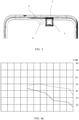
- FIG. 1 is a first structural diagram of a mobile terminal according to an embodiment of the present disclosure. As shown in FIG. 1 , this embodiment provides the mobile terminal.
- the mobile terminal includes: a receiver 1, disposed on one side of a center line of the mobile terminal, where a sound outlet hole 3 is provided in a display screen 2 of the mobile terminal, a front cavity sound outlet channel 4 of the receiver 1 is provided inside the mobile terminal, and the front cavity sound outlet channel 4 communicates with the sound outlet hole 3; and a through-hole 5 is provided at the top of the mobile terminal, and the through-hole 5 communicates with the front cavity sound outlet channel 4.
- the sound outlet hole 3 may be a narrow slit or a tiny slit.
- the display screen 2 of the mobile terminal is a plane on which a display screen is located.
- the receiver 1 is disposed at a position in the mobile terminal close to the top.
- the center line of the mobile terminal may be construed as a center line of the display screen 2.
- the center line of the display screen is a center line in a longitudinal direction of the display screen.
- FIG. 1 and FIG. 2 FIG. 1 shows a receiver 1 that is disposed leftward from the middle
- FIG. 2 shows a receiver 1 that is disposed rightward from the middle.
- That the receiver 1 is disposed on one side of the center line of the mobile terminal may be considered that the receiver 1 is biased.
- a front camera of the mobile terminal may be disposed in the middle of the display screen 2.
- the reference numeral 6 in the figure represents the front camera.
- the top of the mobile terminal may be construed as a top face of the mobile terminal, and the top face is adjacent to the display screen 2.
- the through-hole 5 is provided at the top of the mobile terminal, the through-hole 5 communicates with the front cavity sound outlet channel 4, and a sound transmitted out through the front cavity sound outlet channel 4 may be transmitted out through the sound outlet hole 3, and may also be transmitted out through the through-hole 5. This can increase the volume of a sound transmitted out of the mobile terminal during speech receiving, and improve speech receiving quality of the mobile terminal.
- FIG. 4a shows a graph contrasting curves of of distortion at 1020 Hz.
- a dotted line in FIG. 4a shows a curve of distortion for a mobile terminal provided with a through-hole in the case that a sound outlet hole is partly blocked by an earlobe.
- a solid line in FIG. 4a shows a curve of distortion for a mobile terminal not provided with a through-hole in the case that a sound outlet hole is partly blocked by an earlobe.
- FIG. 4b shows a graph contrasting curves of distortion at a low frequency.
- a dotted line in FIG. 4b shows a curve of distortion for a mobile terminal provided with a through-hole in the case that a sound outlet hole is partly blocked.
- a solid line in FIG. 4b shows a curve of distortion for a mobile terminal not provided with a through-hole in the case that a sound outlet hole is partly blocked by an earlobe.
- the receiver 1 and the through-hole 5 are provided on a same side of the center line. That is, in a case that the receiver 1 is located on a first side of the center line, the through-hole 5 is also located on the first side of the center line.
- the first side may be a left side or a right side.
- the mobile terminal includes a left frame and a right frame.
- the display screen is disposed between the left frame and the right frame. That the receiver 1 is located on the first side of the center line may be construed as that the receiver 1 is close to the left frame, or the receiver 1 is close to the right frame.
- the through-hole 5 is also close to the left frame.
- the through-hole 5 is also close to the right frame.
- the receiver 1 and the through-hole 5 are provided on the same side of the center line (the left side or the right side of the center line), a sound made by the receiver 1 is transmitted out through the through-hole 5 for a relatively short distance. This can reduce an adverse effect of a transmission distance on the volume and tone quality and resolve the problem of low volume and poor tone quality caused by a far transmission distance.
- the size and position of the through-hole may be provided as appropriate to an actual situation. However, the through-hole needs to be provided near the receiver, so as to avoid decline of sound performance due to increase of a sound transmitting length.
- a slide groove is provided inside the mobile terminal, the slide groove communicates with the through-hole 5, a slider 7 capable of sliding is disposed in the slide groove, and the slider 7 slides between a first position and a second position of the slide groove; and in a case that the slider 7 is located in the first position, the slider 7 closes the through-hole 5, and in a case that the slider 7 is located in the second position, the slider 7 opens the through-hole 5.
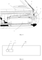
- FIG. 6 and FIG. 7 show sectional views of a mobile terminal.
- the reference numeral 100 in the figures represents a screen of the mobile terminal.
- FIG. 6 shows a positional relationship between the slider 7 and the through-hole 5 when the slider 7 is in the second position.
- the slider 7 shows a positional relationship between the slider 7 and the through-hole 5 when the slider 7 is in the first position.
- the slider 7 may match the through-hole 5 in shape.
- the slider 7 may also be circular; and if the cross section of the through-hole 5 is rectangular, the slider 7 may also be rectangular.
- the slider 7 is slightly larger than the cross section of the through-hole 5. In this way, when the slider 7 is in the first position, it can effectively ensured that the slider 7 can block the through-hole 5.
- the slider 7 When the slider 7 is in the first position, the slider 7 closes the through-hole 5, and a sound made by the receiver 1 cannot be transmitted out through the through-hole 5. This may prevent sound leakage and protect user privacy.
- the slider 7 When the slider 7 is in the second position, the slider 7 opens the through-hole 5, and a sound made by the receiver 1 is transmitted out through the through-hole 5. This can increase the volume of a sound transmitted out of the mobile terminal during speech receiving, and improve a speech receiving quality of the mobile terminal.
- the slider 7 may alternatively be designed to close the through-hole 5 in the first position and fully open the through-hole 5 (that is, not block the through-hole 5 at all) in the second position, and the slider 7, at a position between the first position and the second position, partially blocks the through-hole 5.
- an air filter is provided in the through-hole 5, so as to prevent dust from falling into the through-hole 5 to block the through-hole 5 and affect sound transmission.
- the receiver 1 and the slide groove are provided on a same side of the center line.
- the receiver 1 and the through-hole 5 are provided on the same side of the center line. This may reduce a length of the slide groove communicating with the through-hole, reducing costs of manufacturing the slide groove and reducing a space occupied by the slide groove.
- That the slider 7 slides in the slide groove may include two implementations.
- the slider 7 in the slide groove is capable of freely sliding under gravitational force.
- a drive mechanism is disposed inside the mobile terminal, where the drive mechanism is connected to the slider 7, and the drive mechanism is configured to drive the slider 7 to slide between the first position and the second position.
- the slider 7 in the slide groove freely slides under gravitational force.
- the slider 7 freely slides under gravitational force, to close the through-hole 5, so as to prevent sound leakage and protect user privacy; or to open the through-hole 5, so as to increase the volume of a sound transmitted out of the mobile terminal during speech receiving, and improve a speech receiving quality of the mobile terminal.
- a limiting member for fixing the slider 7 may be disposed in the first position or the second position of the slide groove, so as to prevent the slider 7 from sliding in the slide groove when no speech is being received.
- the limiting member relieves the fixture on the slider 7, and the slider 7 is capable of freely sliding in the slide groove under gravitational force, to close the through-hole 5 or open the through-hole 5.
- a drive mechanism is disposed inside the mobile terminal, where the drive mechanism is connected to the slider 7, and the drive mechanism is configured to drive the slider 7 to slide between the first position and the second position.
- the drive mechanism may be connected to a control chip of the mobile terminal.
- the control chip controls, based on an input operation of a user, the drive mechanism to drive the slider 7 to slide.
- the user may set a position of the slider 7 based on an actual demand, to selectively open the through-hole 5 or close the through-hole 5.
- the receiver 1 being disposed leftward from the middle is used as an example.
- the receiver 1 is disposed leftward.
- the slide groove is provided on the left side of the through-hole 5.
- the through-hole 5 communicates with the front cavity sound outlet channel 4, and a sound made by the receiver 1 may be transmitted out through the through-hole 5.
- the receiver 1 is disposed leftward, when the user is receiving a speech with the left ear, a first part of the sound outlet hole 3 (the first part is a part of the sound outlet hole 3 close to the front cavity sound outlet channel 4) is blocked, and a sound is transmitted out only through a second part of the sound outlet hole 3 (the second part is a part of the sound outlet hole 3 far from the front cavity sound outlet channel 4), which is low in volume and poor in tone quality.
- a sound made by the receiver 1 may be transmitted out through the through-hole 5. This can increase the volume of a sound transmitted out of the mobile terminal during speech receiving, and improve a speech receiving quality of the mobile terminal, thereby resolving the problem of low volume and poor tone quality of the mobile terminal.
- the receiver 1 is disposed leftward.
- the slide groove is provided on the left side of the through-hole 5.
- the through-hole 5 does not communicate with the front cavity sound outlet channel 4, and a sound made by the receiver 1 cannot be transmitted out through the through-hole 5.
- the receiver 1 is disposed leftward, when the user is receiving a speech with the right ear, a first part of the sound outlet hole 3 (the first part is a part of the sound outlet hole 3 close to the front cavity sound outlet channel 4) is not blocked, and a sound transmitted out through the sound outlet hole 3 is not affected.
- a sound transmitted out of the mobile terminal is normal, user experience is not affected, and there is no need to use the through-hole 5 to assist in transmitting a sound.
- the slider 7 closes the through-hole 5, and a sound made by the receiver 1 may not be transmitted out through the through-hole 5. This can effectively prevent sound leakage and protect user privacy.
- the mobile terminal in the foregoing embodiment may be a mobile phone, a tablet computer (Tablet Personal Computer), a laptop computer (Laptop Computer), a personal digital assistant (personal digital assistant, PDA), a mobile internet device (Mobile Internet Device, MID), a wearable device (Wearable Device), or the like.
Landscapes
- Engineering & Computer Science (AREA)
- Signal Processing (AREA)
- Physics & Mathematics (AREA)
- Acoustics & Sound (AREA)
- Health & Medical Sciences (AREA)
- Otolaryngology (AREA)
- Telephone Set Structure (AREA)
Abstract
Description
- This application claims priority to
Chinese Patent Application No. 201910334752.4, filed in China on, April 24, 2019 - The present disclosure relates to the field of communications technologies, and in particular, to a mobile terminal.
- A receiver of a mobile terminal is disposed inside the mobile terminal, and specifically at a position of the mobile terminal close to the top. As the receiver of the mobile terminal is not arranged in the middle of the mobile terminal, the receiver is leftward or rightward from the middle (that is, the receiver is closer to a left side of the mobile terminal, or the receiver is closer to a right side of the mobile terminal). As such, because a narrow slit for sounds to reach out is located in the top middle of a display screen of the mobile terminal, a sound outlet channel that communicates between the receiver and the narrow slit on the display screen is also leftward or rightward from the middle.
- The receiver being arranged leftward from the middle is used as an example. When a user uses a mobile terminal with a receiver arranged leftward to receive a speech, if the user listens with the left ear, a part of the left ear in contact with the mobile terminal may block a first part of the narrow slit (the first part is a part of the narrow slit close to the sound outlet channel), such that a sound made by the receiver may be transmitted out only through a second part of the narrow slit (the second part is a part of the narrow slit far from the sound outlet channel).
- Because a distance between the receiver and the second part of the narrow slit is relatively farther, a sound transmitted out through the second part of the narrow slit is low in volume and poor in tone quality, which will affect a speech receiving quality of the mobile terminal.
- Embodiments of the present disclosure provide a mobile terminal, so as to resolve the problem of low volume and low tone quality in the related technologies when a mobile terminal receives a speech because a narrow slit of the mobile terminal is blocked.
- To resolve the foregoing technical problem, an embodiment provides a mobile terminal, where the mobile terminal includes:
- a receiver, disposed on one side of a center line of the mobile terminal, where
- a sound outlet hole is provided in a display screen of the mobile terminal, a front cavity sound outlet channel of the receiver is provided inside the mobile terminal, and the front cavity sound outlet channel communicates with the sound outlet hole; and
- a through-hole is provided at the top of the mobile terminal, and the through-hole communicates with the front cavity sound outlet channel.
- Further, the receiver and the through-hole are provided on a same side of the center line.
- Further, a slide groove is provided inside the mobile terminal, the slide groove communicates with the through-hole, a slider capable of sliding is disposed in the slide groove, and the slider slides between a first position and a second position of the slide groove; and
in a case that the slider is located in the first position, the slider closes the through-hole, and in a case that the slider is located in the second position, the slider opens the through-hole. - Further, the receiver and the slide groove are provided on a same side of the center line.
- Further, the slider in the slide groove is capable of freely sliding under gravitational force.
- Further, a limiting member for fixing the slider is disposed in the first position or the second position of the slide groove.
- Further, a drive mechanism is disposed inside the mobile terminal, where the drive mechanism is connected to the slider, and the drive mechanism is configured to drive the slider to slide between the first position and the second position.
- Further, an air filter is disposed in the through-hole.
- In the embodiments of the present disclosure, the mobile terminal includes: a receiver, disposed on one side of a center line of the mobile terminal, where a sound outlet hole is provided in a display screen of the mobile terminal, a front cavity sound outlet channel of the receiver is provided inside the mobile terminal, and the front cavity sound outlet channel communicates with the sound outlet hole; and a through-hole is provided at the top of the mobile terminal, and the through-hole communicates with the front cavity sound outlet channel. In this way, a sound transmitted out through the front cavity sound outlet channel may be transmitted out through the sound outlet hole, and may also be transmitted out through the through-hole. This can increase the volume of a sound transmitted out of the mobile terminal during speech receiving, and improve a speech receiving quality of the mobile terminal.
-
-
FIG. 1 is a first structural diagram of a mobile terminal according to an embodiment of the present disclosure; -
FIG. 2 is a second structural diagram of a mobile terminal according to an embodiment of the present disclosure; -
FIG. 3 is a third structural diagram of a mobile terminal according to an embodiment of the present disclosure; -
FIG. 4a is a first graph contrasting curves of distortion according to an embodiment of the present disclosure; -
FIG. 4b is a second graph contrasting curves of distortion according to an embodiment of the present disclosure; -
FIG. 5 is a fourth structural diagram of a mobile terminal according to an embodiment of the present disclosure; -
FIG. 6 is a fifth structural diagram of a mobile terminal according to an embodiment of the present disclosure; and -
FIG. 7 is a sixth structural diagram of a mobile terminal according to an embodiment of the present disclosure. - The following clearly and completely describes the technical solutions in the embodiments of the present disclosure with reference to the accompanying drawings in the embodiments of the present disclosure. Apparently, the described embodiments are merely some rather than all of the embodiments of the present disclosure. All other embodiments obtained by persons of ordinary skill in the art without creative efforts based on the embodiments of the present disclosure shall fall within the protection scope of the present disclosure.
- Referring to
FIG. 1, FIG. 1 is a first structural diagram of a mobile terminal according to an embodiment of the present disclosure. As shown inFIG. 1 , this embodiment provides the mobile terminal. The mobile terminal includes:
areceiver 1, disposed on one side of a center line of the mobile terminal, where asound outlet hole 3 is provided in adisplay screen 2 of the mobile terminal, a front cavitysound outlet channel 4 of thereceiver 1 is provided inside the mobile terminal, and the front cavitysound outlet channel 4 communicates with thesound outlet hole 3; and a through-hole 5 is provided at the top of the mobile terminal, and the through-hole 5 communicates with the front cavitysound outlet channel 4. - Specifically, the
sound outlet hole 3 may be a narrow slit or a tiny slit. Thedisplay screen 2 of the mobile terminal is a plane on which a display screen is located. Thereceiver 1 is disposed at a position in the mobile terminal close to the top. The center line of the mobile terminal may be construed as a center line of thedisplay screen 2. As shown inFIG. 1 , the center line of the display screen is a center line in a longitudinal direction of the display screen. As shown inFIG. 1 andFIG. 2 ,FIG. 1 shows areceiver 1 that is disposed leftward from the middle, andFIG. 2 shows areceiver 1 that is disposed rightward from the middle. That thereceiver 1 is disposed on one side of the center line of the mobile terminal may be considered that thereceiver 1 is biased. When thereceiver 1 is biased, a front camera of the mobile terminal may be disposed in the middle of thedisplay screen 2. As shown inFIG. 3 , thereference numeral 6 in the figure represents the front camera. - The top of the mobile terminal may be construed as a top face of the mobile terminal, and the top face is adjacent to the
display screen 2. The through-hole 5 is provided at the top of the mobile terminal, the through-hole 5 communicates with the front cavitysound outlet channel 4, and a sound transmitted out through the front cavitysound outlet channel 4 may be transmitted out through thesound outlet hole 3, and may also be transmitted out through the through-hole 5. This can increase the volume of a sound transmitted out of the mobile terminal during speech receiving, and improve speech receiving quality of the mobile terminal. - When a receiver under test is biased, contrast results of sound loudness and distortion of the mobile terminal with and without a through-hole at the top are shown in Table 1.
Table 1 Receive loudness rating (RLR) Distortion (1020 Hz) Distortion (low frequency) With through-hole 1.91 18.22 18.62 Without through-hole -0.17 31.98 33.67 - From Table 1, it can be learned that, in a case that a sound outlet hole is blocked, when a through-hole is provided, loudness is improved by 2 db, and distortion is mitigated a lot. In addition,
FIG. 4a shows a graph contrasting curves of of distortion at 1020 Hz. A dotted line inFIG. 4a shows a curve of distortion for a mobile terminal provided with a through-hole in the case that a sound outlet hole is partly blocked by an earlobe. A solid line inFIG. 4a shows a curve of distortion for a mobile terminal not provided with a through-hole in the case that a sound outlet hole is partly blocked by an earlobe.FIG. 4b shows a graph contrasting curves of distortion at a low frequency. A dotted line inFIG. 4b shows a curve of distortion for a mobile terminal provided with a through-hole in the case that a sound outlet hole is partly blocked. A solid line inFIG. 4b shows a curve of distortion for a mobile terminal not provided with a through-hole in the case that a sound outlet hole is partly blocked by an earlobe. FromFIG. 4a andFIG. 4b , it can be learned that, when the mobile terminal is provided with a through-hole, distortion of sound is mitigated a lot. - Optionally, the
receiver 1 and the through-hole 5 are provided on a same side of the center line. That is, in a case that thereceiver 1 is located on a first side of the center line, the through-hole 5 is also located on the first side of the center line. The first side may be a left side or a right side. The mobile terminal includes a left frame and a right frame. The display screen is disposed between the left frame and the right frame. That thereceiver 1 is located on the first side of the center line may be construed as that thereceiver 1 is close to the left frame, or thereceiver 1 is close to the right frame. When thereceiver 1 is close to the left frame, the through-hole 5 is also close to the left frame. When thereceiver 1 is close to the right frame, the through-hole 5 is also close to the right frame. - When the
receiver 1 and the through-hole 5 are provided on the same side of the center line (the left side or the right side of the center line), a sound made by thereceiver 1 is transmitted out through the through-hole 5 for a relatively short distance. This can reduce an adverse effect of a transmission distance on the volume and tone quality and resolve the problem of low volume and poor tone quality caused by a far transmission distance. The size and position of the through-hole may be provided as appropriate to an actual situation. However, the through-hole needs to be provided near the receiver, so as to avoid decline of sound performance due to increase of a sound transmitting length. - Optionally, as shown in
FIG. 5 , a slide groove is provided inside the mobile terminal, the slide groove communicates with the through-hole 5, aslider 7 capable of sliding is disposed in the slide groove, and theslider 7 slides between a first position and a second position of the slide groove; and in a case that theslider 7 is located in the first position, theslider 7 closes the through-hole 5, and in a case that theslider 7 is located in the second position, theslider 7 opens the through-hole 5. - Specifically, when the
slider 7 is in the first position, theslider 7 closes the through-hole 5. In this case, the through-hole 5 does not communicate with the front cavitysound outlet channel 4, and a sound made by thereceiver 1 cannot be transmitted out through the through-hole 5. When theslider 7 is in the second position, theslider 7 opens the through-hole 5. In this case, the through-hole 5 communicates with the front cavitysound outlet channel 4, and a sound made by thereceiver 1 can be transmitted out through the through-hole 5.FIG. 6 andFIG. 7 show sectional views of a mobile terminal. Thereference numeral 100 in the figures represents a screen of the mobile terminal.FIG. 6 shows a positional relationship between theslider 7 and the through-hole 5 when theslider 7 is in the second position.FIG. 7 shows a positional relationship between theslider 7 and the through-hole 5 when theslider 7 is in the first position. Theslider 7 may match the through-hole 5 in shape. For example, if a cross section of the through-hole 5 is circular, theslider 7 may also be circular; and if the cross section of the through-hole 5 is rectangular, theslider 7 may also be rectangular. In size, theslider 7 is slightly larger than the cross section of the through-hole 5. In this way, when theslider 7 is in the first position, it can effectively ensured that theslider 7 can block the through-hole 5. - When the
slider 7 is in the first position, theslider 7 closes the through-hole 5, and a sound made by thereceiver 1 cannot be transmitted out through the through-hole 5. This may prevent sound leakage and protect user privacy. When theslider 7 is in the second position, theslider 7 opens the through-hole 5, and a sound made by thereceiver 1 is transmitted out through the through-hole 5. This can increase the volume of a sound transmitted out of the mobile terminal during speech receiving, and improve a speech receiving quality of the mobile terminal. Certainly, theslider 7 may alternatively be designed to close the through-hole 5 in the first position and fully open the through-hole 5 (that is, not block the through-hole 5 at all) in the second position, and theslider 7, at a position between the first position and the second position, partially blocks the through-hole 5. In addition, an air filter is provided in the through-hole 5, so as to prevent dust from falling into the through-hole 5 to block the through-hole 5 and affect sound transmission. - The
receiver 1 and the slide groove are provided on a same side of the center line. Thereceiver 1 and the through-hole 5 are provided on the same side of the center line. This may reduce a length of the slide groove communicating with the through-hole, reducing costs of manufacturing the slide groove and reducing a space occupied by the slide groove. - That the
slider 7 slides in the slide groove may include two implementations. In a first implementation, theslider 7 in the slide groove is capable of freely sliding under gravitational force. In a second implementation, a drive mechanism is disposed inside the mobile terminal, where the drive mechanism is connected to theslider 7, and the drive mechanism is configured to drive theslider 7 to slide between the first position and the second position. - In the first implementation, the
slider 7 in the slide groove freely slides under gravitational force. In this way, theslider 7 freely slides under gravitational force, to close the through-hole 5, so as to prevent sound leakage and protect user privacy; or to open the through-hole 5, so as to increase the volume of a sound transmitted out of the mobile terminal during speech receiving, and improve a speech receiving quality of the mobile terminal. - To avoid that the
slider 7 slides under gravitational force along with an angle change of the mobile terminal when no speech is being received, a limiting member for fixing theslider 7 may be disposed in the first position or the second position of the slide groove, so as to prevent theslider 7 from sliding in the slide groove when no speech is being received. When the mobile terminal is receiving a speech, the limiting member relieves the fixture on theslider 7, and theslider 7 is capable of freely sliding in the slide groove under gravitational force, to close the through-hole 5 or open the through-hole 5. - In the second implementation, a drive mechanism is disposed inside the mobile terminal, where the drive mechanism is connected to the
slider 7, and the drive mechanism is configured to drive theslider 7 to slide between the first position and the second position. The drive mechanism may be connected to a control chip of the mobile terminal. The control chip controls, based on an input operation of a user, the drive mechanism to drive theslider 7 to slide. In this case, the user may set a position of theslider 7 based on an actual demand, to selectively open the through-hole 5 or close the through-hole 5. - The
receiver 1 being disposed leftward from the middle is used as an example. Thereceiver 1 is disposed leftward. The slide groove is provided on the left side of the through-hole 5. When a user is receiving a speech with the left ear, the left top of the mobile terminal is located below the right top of the mobile terminal, theslider 7 slides to the second position under gravitational force, or theslider 7 is driven by the drive mechanism to slide to the second position. In this case, the through-hole 5 communicates with the front cavitysound outlet channel 4, and a sound made by thereceiver 1 may be transmitted out through the through-hole 5. Because thereceiver 1 is disposed leftward, when the user is receiving a speech with the left ear, a first part of the sound outlet hole 3 (the first part is a part of thesound outlet hole 3 close to the front cavity sound outlet channel 4) is blocked, and a sound is transmitted out only through a second part of the sound outlet hole 3 (the second part is a part of thesound outlet hole 3 far from the front cavity sound outlet channel 4), which is low in volume and poor in tone quality. However, based on the implementations of this embodiment, a sound made by thereceiver 1 may be transmitted out through the through-hole 5. This can increase the volume of a sound transmitted out of the mobile terminal during speech receiving, and improve a speech receiving quality of the mobile terminal, thereby resolving the problem of low volume and poor tone quality of the mobile terminal. - The
receiver 1 is disposed leftward. The slide groove is provided on the left side of the through-hole 5. When the user is receiving a speech with the right ear, the right top of the mobile terminal is located below the left top of the mobile terminal, theslider 7 slides to the first position under gravitational force, or theslider 7 is driven by the drive mechanism to slide to the first position. In this case, the through-hole 5 does not communicate with the front cavitysound outlet channel 4, and a sound made by thereceiver 1 cannot be transmitted out through the through-hole 5. Because thereceiver 1 is disposed leftward, when the user is receiving a speech with the right ear, a first part of the sound outlet hole 3 (the first part is a part of thesound outlet hole 3 close to the front cavity sound outlet channel 4) is not blocked, and a sound transmitted out through thesound outlet hole 3 is not affected. In this case, a sound transmitted out of the mobile terminal is normal, user experience is not affected, and there is no need to use the through-hole 5 to assist in transmitting a sound. In this case, theslider 7 closes the through-hole 5, and a sound made by thereceiver 1 may not be transmitted out through the through-hole 5. This can effectively prevent sound leakage and protect user privacy. - The mobile terminal in the foregoing embodiment may be a mobile phone, a tablet computer (Tablet Personal Computer), a laptop computer (Laptop Computer), a personal digital assistant (personal digital assistant, PDA), a mobile internet device (Mobile Internet Device, MID), a wearable device (Wearable Device), or the like.
- The foregoing descriptions are only specific implementations of the present disclosure, but are not intended to limit the protection scope of the present disclosure. Any variation or replacement readily figured out by persons skilled in the art within the technical scope disclosed in the present disclosure shall fall within the protection scope of the present disclosure. Therefore, the protection scope of the present disclosure shall be subject to the protection scope of the claims.
Claims (8)
- A mobile terminal, comprising:a receiver, disposed on one side of a center line of the mobile terminal, whereina sound outlet hole is provided in a display screen of the mobile terminal, a front cavity sound outlet channel of the receiver is provided inside the mobile terminal, and the front cavity sound outlet channel communicates with the sound outlet hole; anda through-hole is provided at the top of the mobile terminal, and the through-hole communicates with the front cavity sound outlet channel.
- The mobile terminal according to claim 1, wherein the receiver and the through-hole are provided on a same side of the center line.
- The mobile terminal according to claim 1, wherein a slide groove is provided inside the mobile terminal, the slide groove communicates with the through-hole, a slider capable of sliding is disposed in the slide groove, and the slider slides between a first position and a second position of the slide groove; and
in a case that the slider is located in the first position, the slider closes the through-hole, and in a case that the slider is located in the second position, the slider opens the through-hole. - The mobile terminal according to claim 3, wherein the receiver and the slide groove are provided on a same side of the center line.
- The mobile terminal according to claim 3, wherein the slider in the slide groove is capable of freely sliding under gravitational force.
- The mobile terminal according to claim 5, wherein a limiting member for fixing the slider is disposed in the first position or the second position of the slide groove.
- The mobile terminal according to claim 3, wherein a drive mechanism is disposed inside the mobile terminal, wherein the drive mechanism is connected to the slider, and the drive mechanism is configured to drive the slider to slide between the first position and the second position.
- The mobile terminal according to any one of claims 1 to 7, wherein an air filter is disposed in the through-hole.
Applications Claiming Priority (2)
| Application Number | Priority Date | Filing Date | Title |
|---|---|---|---|
| CN201910334752.4A CN110166587B (en) | 2019-04-24 | 2019-04-24 | a mobile terminal |
| PCT/CN2020/082083 WO2020216003A1 (en) | 2019-04-24 | 2020-03-30 | Mobile terminal |
Publications (2)
| Publication Number | Publication Date |
|---|---|
| EP3962044A1 true EP3962044A1 (en) | 2022-03-02 |
| EP3962044A4 EP3962044A4 (en) | 2022-06-08 |
Family
ID=67639969
Family Applications (1)
| Application Number | Title | Priority Date | Filing Date |
|---|---|---|---|
| EP20794603.9A Pending EP3962044A4 (en) | 2019-04-24 | 2020-03-30 | MOBILE TERMINAL |
Country Status (6)
| Country | Link |
|---|---|
| US (1) | US20220046121A1 (en) |
| EP (1) | EP3962044A4 (en) |
| KR (1) | KR102569403B1 (en) |
| CN (1) | CN110166587B (en) |
| BR (1) | BR112021021177A2 (en) |
| WO (1) | WO2020216003A1 (en) |
Families Citing this family (6)
| Publication number | Priority date | Publication date | Assignee | Title |
|---|---|---|---|---|
| CN110166587B (en) * | 2019-04-24 | 2021-08-03 | 维沃移动通信有限公司 | a mobile terminal |
| CN111245987A (en) * | 2020-02-03 | 2020-06-05 | Oppo广东移动通信有限公司 | Terminal Equipment |
| CN111787145B (en) * | 2020-06-28 | 2021-09-07 | 维沃移动通信有限公司 | Electronic equipment |
| CN112188378B (en) * | 2020-09-28 | 2021-08-17 | 维沃移动通信有限公司 | Sound production optimization method, device, electronic device, and readable storage medium for electronic equipment |
| KR102728943B1 (en) * | 2021-03-10 | 2024-11-12 | 삼성전자 주식회사 | Electronice device including speaker structure |
| US12279088B2 (en) * | 2022-12-05 | 2025-04-15 | Oxti Pte Ltd | Electronic device with movable sound source |
Family Cites Families (15)
| Publication number | Priority date | Publication date | Assignee | Title |
|---|---|---|---|---|
| US6104808A (en) * | 1998-08-31 | 2000-08-15 | Motorola, Inc. | Portable communication device with speakerphone operation |
| JP2001230841A (en) * | 2000-02-18 | 2001-08-24 | Matsushita Electric Ind Co Ltd | Mobile terminal |
| US6819946B2 (en) * | 2002-10-04 | 2004-11-16 | Sony Ericsson Mobile Communications Ab | Apparatus and method for controlling source of sound emitted from a mobile terminal |
| JP2006279260A (en) * | 2005-03-28 | 2006-10-12 | Nec Saitama Ltd | Portable terminal |
| DE102011009876B4 (en) * | 2010-02-01 | 2012-08-23 | Constin Gmbh | Portable communication device |
| CN102455579A (en) * | 2010-10-18 | 2012-05-16 | 台达电子工业股份有限公司 | Heat dissipation device and projector |
| KR101802239B1 (en) * | 2011-06-14 | 2017-11-29 | 삼성전자주식회사 | Speaker apparatus |
| CN104580612B (en) * | 2013-10-22 | 2019-02-05 | 联想(北京)有限公司 | The earphone device of communicating terminal and communicating terminal including the earphone device |
| CN203618051U (en) * | 2013-11-26 | 2014-05-28 | 东莞宇龙通信科技有限公司 | Mobile terminal sound playing structure, mobile terminal rear cover and mobile terminal |
| JP6541988B2 (en) * | 2015-02-25 | 2019-07-10 | 京セラ株式会社 | Electronics |
| CN106302875B (en) * | 2016-08-04 | 2019-03-15 | 青岛海信移动通信技术股份有限公司 | mobile terminal |
| CN107172533B (en) * | 2017-06-01 | 2019-09-13 | 奇酷互联网络科技(深圳)有限公司 | A kind of method and apparatus and mobile terminal for selecting sound direction |
| CN108574919B (en) * | 2018-03-19 | 2020-02-07 | 维沃移动通信有限公司 | Mobile terminal |
| CN108769311B (en) * | 2018-05-29 | 2020-10-27 | 维沃移动通信有限公司 | Mobile terminal control method and mobile terminal |
| CN110166587B (en) * | 2019-04-24 | 2021-08-03 | 维沃移动通信有限公司 | a mobile terminal |
-
2019
- 2019-04-24 CN CN201910334752.4A patent/CN110166587B/en active Active
-
2020
- 2020-03-30 BR BR112021021177A patent/BR112021021177A2/en unknown
- 2020-03-30 EP EP20794603.9A patent/EP3962044A4/en active Pending
- 2020-03-30 WO PCT/CN2020/082083 patent/WO2020216003A1/en not_active Ceased
- 2020-03-30 KR KR1020217036580A patent/KR102569403B1/en active Active
-
2021
- 2021-10-21 US US17/506,961 patent/US20220046121A1/en not_active Abandoned
Also Published As
| Publication number | Publication date |
|---|---|
| KR20210146408A (en) | 2021-12-03 |
| KR102569403B1 (en) | 2023-08-22 |
| WO2020216003A1 (en) | 2020-10-29 |
| EP3962044A4 (en) | 2022-06-08 |
| US20220046121A1 (en) | 2022-02-10 |
| CN110166587A (en) | 2019-08-23 |
| BR112021021177A2 (en) | 2021-12-14 |
| CN110166587B (en) | 2021-08-03 |
Similar Documents
| Publication | Publication Date | Title |
|---|---|---|
| US20220046121A1 (en) | Mobile terminal | |
| CN207968576U (en) | Mobile phone | |
| EP3300387B1 (en) | Valve for acoustic port | |
| KR101169868B1 (en) | Acoustic reconfiguration devices and methods | |
| CN109040385B (en) | Terminal | |
| US20090169040A1 (en) | Devices and methods for enhancing the frequency output of a portable audio device | |
| US20090129623A1 (en) | Speaker Apparatus in a Wireless Communication Device | |
| US11856349B2 (en) | Mobile terminal | |
| CN110267157B (en) | mobile terminal | |
| KR100678276B1 (en) | Antenna device of mobile terminal | |
| EP2804363A1 (en) | Cover for electronic device | |
| US10887686B2 (en) | Directional microphone | |
| KR100703466B1 (en) | Slim portable terminal | |
| US20230199356A1 (en) | Speaker Assembly and Electronic Device | |
| CN208079140U (en) | Mobile terminal | |
| CN208174749U (en) | Mobile terminal | |
| US20210227341A1 (en) | Earphone with Volume Monitoring | |
| US20240187784A1 (en) | Electronic device with movable sound source | |
| US7747004B2 (en) | Devices and methods for acoustic usability | |
| CN213485161U (en) | Electronic equipment | |
| CN221597941U (en) | Electronic equipment | |
| KR100393806B1 (en) | Mobile image phone having camera protecting device | |
| JP4720678B2 (en) | Mobile phone equipment | |
| CN110138917B (en) | Mobile terminal | |
| WO2019148660A1 (en) | Slide type terminal |
Legal Events
| Date | Code | Title | Description |
|---|---|---|---|
| STAA | Information on the status of an ep patent application or granted ep patent |
Free format text: STATUS: THE INTERNATIONAL PUBLICATION HAS BEEN MADE |
|
| PUAI | Public reference made under article 153(3) epc to a published international application that has entered the european phase |
Free format text: ORIGINAL CODE: 0009012 |
|
| STAA | Information on the status of an ep patent application or granted ep patent |
Free format text: STATUS: REQUEST FOR EXAMINATION WAS MADE |
|
| 17P | Request for examination filed |
Effective date: 20211109 |
|
| AK | Designated contracting states |
Kind code of ref document: A1 Designated state(s): AL AT BE BG CH CY CZ DE DK EE ES FI FR GB GR HR HU IE IS IT LI LT LU LV MC MK MT NL NO PL PT RO RS SE SI SK SM TR |
|
| A4 | Supplementary search report drawn up and despatched |
Effective date: 20220511 |
|
| RIC1 | Information provided on ipc code assigned before grant |
Ipc: H04R 1/36 20060101ALI20220505BHEP Ipc: H04R 1/30 20060101ALI20220505BHEP Ipc: H04M 1/03 20060101ALI20220505BHEP Ipc: H04M 1/02 20060101AFI20220505BHEP |
|
| DAV | Request for validation of the european patent (deleted) | ||
| DAX | Request for extension of the european patent (deleted) | ||
| STAA | Information on the status of an ep patent application or granted ep patent |
Free format text: STATUS: EXAMINATION IS IN PROGRESS |
|
| 17Q | First examination report despatched |
Effective date: 20230725 |
|
| GRAP | Despatch of communication of intention to grant a patent |
Free format text: ORIGINAL CODE: EPIDOSNIGR1 |
|
| STAA | Information on the status of an ep patent application or granted ep patent |
Free format text: STATUS: GRANT OF PATENT IS INTENDED |
|
| INTG | Intention to grant announced |
Effective date: 20260319 |
|
| GRAS | Grant fee paid |
Free format text: ORIGINAL CODE: EPIDOSNIGR3 |