EP3962013B1 - Terminal device and method for facilitating communication between terminal devices - Google Patents
Terminal device and method for facilitating communication between terminal devices Download PDFInfo
- Publication number
- EP3962013B1 EP3962013B1 EP21190966.8A EP21190966A EP3962013B1 EP 3962013 B1 EP3962013 B1 EP 3962013B1 EP 21190966 A EP21190966 A EP 21190966A EP 3962013 B1 EP3962013 B1 EP 3962013B1
- Authority
- EP
- European Patent Office
- Prior art keywords
- mapping
- terminal device
- tbs
- mcs
- mappings
- Prior art date
- Legal status (The legal status is an assumption and is not a legal conclusion. Google has not performed a legal analysis and makes no representation as to the accuracy of the status listed.)
- Active
Links
- 238000000034 method Methods 0.000 title claims description 44
- 238000004891 communication Methods 0.000 title claims description 25
- 238000013507 mapping Methods 0.000 claims description 225
- 230000015654 memory Effects 0.000 claims description 21
- 230000005540 biological transmission Effects 0.000 claims description 13
- 230000001419 dependent effect Effects 0.000 claims description 11
- 125000002306 tributylsilyl group Chemical group C(CCC)[Si](CCCC)(CCCC)* 0.000 claims 11
- 238000004590 computer program Methods 0.000 description 15
- 238000010586 diagram Methods 0.000 description 6
- 238000012545 processing Methods 0.000 description 4
- 238000007792 addition Methods 0.000 description 1
- 238000005516 engineering process Methods 0.000 description 1
- 230000007774 longterm Effects 0.000 description 1
- 238000012986 modification Methods 0.000 description 1
- 230000004048 modification Effects 0.000 description 1
- 230000010363 phase shift Effects 0.000 description 1
Images


Classifications
-
- H—ELECTRICITY
- H04—ELECTRIC COMMUNICATION TECHNIQUE
- H04L—TRANSMISSION OF DIGITAL INFORMATION, e.g. TELEGRAPHIC COMMUNICATION
- H04L1/00—Arrangements for detecting or preventing errors in the information received
- H04L1/0001—Systems modifying transmission characteristics according to link quality, e.g. power backoff
- H04L1/0002—Systems modifying transmission characteristics according to link quality, e.g. power backoff by adapting the transmission rate
- H04L1/0003—Systems modifying transmission characteristics according to link quality, e.g. power backoff by adapting the transmission rate by switching between different modulation schemes
-
- H—ELECTRICITY
- H04—ELECTRIC COMMUNICATION TECHNIQUE
- H04L—TRANSMISSION OF DIGITAL INFORMATION, e.g. TELEGRAPHIC COMMUNICATION
- H04L1/00—Arrangements for detecting or preventing errors in the information received
- H04L1/0001—Systems modifying transmission characteristics according to link quality, e.g. power backoff
- H04L1/0023—Systems modifying transmission characteristics according to link quality, e.g. power backoff characterised by the signalling
- H04L1/0025—Transmission of mode-switching indication
-
- H—ELECTRICITY
- H04—ELECTRIC COMMUNICATION TECHNIQUE
- H04L—TRANSMISSION OF DIGITAL INFORMATION, e.g. TELEGRAPHIC COMMUNICATION
- H04L1/00—Arrangements for detecting or preventing errors in the information received
- H04L1/0001—Systems modifying transmission characteristics according to link quality, e.g. power backoff
- H04L1/0015—Systems modifying transmission characteristics according to link quality, e.g. power backoff characterised by the adaptation strategy
- H04L1/0016—Systems modifying transmission characteristics according to link quality, e.g. power backoff characterised by the adaptation strategy involving special memory structures, e.g. look-up tables
-
- H—ELECTRICITY
- H04—ELECTRIC COMMUNICATION TECHNIQUE
- H04L—TRANSMISSION OF DIGITAL INFORMATION, e.g. TELEGRAPHIC COMMUNICATION
- H04L1/00—Arrangements for detecting or preventing errors in the information received
- H04L1/12—Arrangements for detecting or preventing errors in the information received by using return channel
- H04L1/16—Arrangements for detecting or preventing errors in the information received by using return channel in which the return channel carries supervisory signals, e.g. repetition request signals
- H04L1/18—Automatic repetition systems, e.g. Van Duuren systems
- H04L1/1829—Arrangements specially adapted for the receiver end
- H04L1/1861—Physical mapping arrangements
-
- H—ELECTRICITY
- H04—ELECTRIC COMMUNICATION TECHNIQUE
- H04L—TRANSMISSION OF DIGITAL INFORMATION, e.g. TELEGRAPHIC COMMUNICATION
- H04L27/00—Modulated-carrier systems
- H04L27/0012—Modulated-carrier systems arrangements for identifying the type of modulation
-
- H—ELECTRICITY
- H04—ELECTRIC COMMUNICATION TECHNIQUE
- H04L—TRANSMISSION OF DIGITAL INFORMATION, e.g. TELEGRAPHIC COMMUNICATION
- H04L27/00—Modulated-carrier systems
- H04L27/32—Carrier systems characterised by combinations of two or more of the types covered by groups H04L27/02, H04L27/10, H04L27/18 or H04L27/26
- H04L27/34—Amplitude- and phase-modulated carrier systems, e.g. quadrature-amplitude modulated carrier systems
- H04L27/36—Modulator circuits; Transmitter circuits
-
- H—ELECTRICITY
- H04—ELECTRIC COMMUNICATION TECHNIQUE
- H04L—TRANSMISSION OF DIGITAL INFORMATION, e.g. TELEGRAPHIC COMMUNICATION
- H04L1/00—Arrangements for detecting or preventing errors in the information received
- H04L1/12—Arrangements for detecting or preventing errors in the information received by using return channel
- H04L1/16—Arrangements for detecting or preventing errors in the information received by using return channel in which the return channel carries supervisory signals, e.g. repetition request signals
- H04L1/18—Automatic repetition systems, e.g. Van Duuren systems
- H04L1/1867—Arrangements specially adapted for the transmitter end
- H04L1/1893—Physical mapping arrangements
-
- H—ELECTRICITY
- H04—ELECTRIC COMMUNICATION TECHNIQUE
- H04W—WIRELESS COMMUNICATION NETWORKS
- H04W4/00—Services specially adapted for wireless communication networks; Facilities therefor
- H04W4/30—Services specially adapted for particular environments, situations or purposes
- H04W4/40—Services specially adapted for particular environments, situations or purposes for vehicles, e.g. vehicle-to-pedestrians [V2P]
-
- H—ELECTRICITY
- H04—ELECTRIC COMMUNICATION TECHNIQUE
- H04W—WIRELESS COMMUNICATION NETWORKS
- H04W92/00—Interfaces specially adapted for wireless communication networks
- H04W92/16—Interfaces between hierarchically similar devices
- H04W92/18—Interfaces between hierarchically similar devices between terminal devices
Definitions
- the present disclosure relates to communication technology, and more particularly, to a terminal device and a method for facilitating direct communication between terminal devices.
- V2X Vehicle to Vehicle/Pedestrian/Infrastructure/Network
- LTE Long Term Evolution
- QPSK Quadrature Phase Shift Keying
- QAM 16 Quadrature Amplitude Modulation
- modulation orders and Transport Block Size (TBS) indices are determined from a "Modulation and Coding Scheme (MCS)" field in a Sidelink Control Information (SCI) format.
- MCS Modulation and Coding Scheme
- SCI Sidelink Control Information
- the MCS field contains an MCS index, based on which the corresponding modulation order and TBS can be obtained.
- the scheme for determining modulation orders and TBSs for Physical Uplink Shared Channel (PUSCH) in the LTE is reused in Physical Sidelink Shared Channel (PSSCH).
- Table 1 below shows a mapping from MCS indices (I MCS ) to modulation orders (Q'm) and TBS indices (I TBS ) in the Release 14 V2X.
- Table 1 - Mapping from I MCS to Q'm and I TBS for Release 14 V2X MCS Index I MCS Modulation Order Q m ′ TBS Index I TBS Coding Rate (no retransmission) 0 2 0 0.10 1 2 1 0.15 2 2 2 0.25 3 2 3 0.31 4 2 4 0.36 5 2 5 0.39 6 2 6 0.44 7 2 7 0.57 8 2 8 0.68 9 2 9 0.79 10 2 10 0.44 11 4 10 0.88 12 4 11 0.51 13 4 12 0.59 14 4 13 0.65 15 4 14 0.73 16 4 15 0.78 17 4 16 0.84 18 4 17 0.92 19 4 18 1.01 20 4 19 1.12 21 4 19 1.12 22 4 20 1.20 23 4 21 1.28 24 4 22 1.40 25 4 23 1.51 26 4 24 1.56 27 4 25 1.62 28 4 26 1.92 29 Reserved 30 31
- Table 1 also shows coding rates corresponding to the modulation orders and TBS indices, with no retransmission assumed. Theoretically, a coding rate higher than one would render a transport block not decodable by a receiver. In practice, a transport block having a coding rate higher than a smaller threshold, e.g., 0.93 as discussed in Release 8, would not be decodable. In either criterion, it can be seen from Table 1 that, for 19 ⁇ I MCS ⁇ 28, the coding rates are too high to be decodable at a receiver. In other words, the above Release 14 mapping does not "support" those MCSs in the sense that they are not decodable.
- Release 15 V2X terminals should be backward compatible. That is, Release 15 V2X terminals shall co-exist with Release 14 V2X terminals in the same resource pools and use the same scheduling assignment format (which can be decoded by legacy terminals). Eventually, the Release 14 and Release 15 V2X terminals shall be able to communicate with each other directly over sidelink, which requires the Release 14 V2X terminals to be able to decode PSSCH transmitted from the Release 15 V2X terminals, and vice versa.
- a method in a first terminal device for facilitating direct communication with a second terminal device comprises: transmitting to the second terminal device a Modulation and Coding Scheme (MCS) index, based on which the second terminal device can obtain a modulation order and a Transport Block Size (TBS) in accordance with a first mapping or a second mapping between MCS indices on one hand and modulation orders and TBSs on the other.
- MCS Modulation and Coding Scheme
- TBS Transport Block Size
- the second mapping supports a higher modulation order than those supported by the first mapping.
- the first and second mappings have an overlapped portion.
- the overlapped portion is associated with one or more of modulation orders supported by both the first and second mappings.
- the overlapped portion is associated with coding rates below a predefined threshold.
- each TBS associated with the second mapping is scaled down with respect to a corresponding TBS associated with the first mapping by a factor dependent on a number of Resource Elements, REs, available for data transmission.
- the MCS index is determined by the first terminal device by applying the first mapping when retransmission is configured, or the second mapping when no retransmission is configured and a modulation order and a TBS obtained by applying the first mapping would result in a coding rate higher than a predefined threshold.
- the method further comprises: transmitting to the second terminal device an indicator indicating which of the first and second mappings is applied by the first terminal device.
- the second terminal device supports the first mapping only.
- the first and second terminal devices are communicating directly with each other on a sidelink for vehicular services.
- a method in a first terminal device for facilitating direct communication with a second terminal device comprises: receiving from the second terminal device a Modulation and Coding Scheme (MCS) index determined by the second terminal device by applying a first mapping or a second mapping between MCS indices on one hand and modulation orders and Transport Block Sizes (TBSs) on the other; and obtaining, based on the MCS index, a modulation order and a TBS in accordance with the first or second mapping.
- MCS Modulation and Coding Scheme
- the second mapping supports a higher modulation order than those supported by the first mapping.
- the first and second mappings have an overlapped portion.
- the overlapped portion is associated with one or more of modulation orders supported by both the first and second mappings.
- the overlapped portion is associated with coding rates below a predefined threshold.
- each TBS associated with the second mapping is scaled down with respect to a corresponding TBS associated with the first mapping by a factor dependent on a number of Resource Elements, REs, available for data transmission.
- the modulation order and the TBS are obtained by the first terminal device in accordance with the first mapping when retransmission is configured, or with the second mapping when no retransmission is configured and a modulation order and a TBS obtained in accordance with the first mapping would result in a coding rate higher than a predefined threshold.
- the method further comprises: receiving from the second terminal device an indicator indicating which of the first and second mappings is applied by the second terminal device.
- the second terminal device supports the first mapping only.
- the first and second terminal devices are communicating directly with each other on a sidelink for vehicular services.
- a first terminal device in direct communication with a second terminal device comprises a transceiver, a processor and a memory.
- the memory comprises instructions which when executed by the processor cause the first terminal device to perform the method according to the above first or second aspect.
- mappings between MCS indices on one hand and modulation orders and TBSs on the other are provided.
- a terminal device supporting both mappings can apply one of the two mappings, so as to communicate with another terminal device that may support only one mapping.
- one of the two mappings can be designed to provide higher modulation orders and thus lower but decodable coding rates than the other. In this way, the MCSs can be more efficient.
- first and second etc. may be used herein to describe various elements, these elements should not be limited by these terms. These terms are only used to distinguish one element from another. For example, a first element could be termed a second element, and similarly, a second element could be termed a first element, without departing from the scope of example embodiments.
- the term “and/or” includes any and all combinations of one or more of the associated listed terms.
- Fig. 1 is a flowchart illustrating a method 100 for facilitating direct communication between terminal devices according to an embodiment of the present disclosure.
- the method 100 can be performed at a first terminal device in direct communication with a second terminal device.
- the first and second terminal devices can communicate directly with each other on a sidelink for vehicular services.
- the first terminal device can be a Release 15 V2X terminal as described above and the second terminal device can be a Release 14 or Release 15 V2X terminal.
- the method 100 includes the following step.
- an MCS index is transmitted to the second terminal device.
- the second terminal device can obtain a modulation order and a TBS in accordance with a first mapping or a second mapping between MCS indices on one hand and modulation orders and TBSs on the other.
- the MCS index is determined by the first terminal device by applying the first or second mapping.
- Table 3 shows an example of mappings from MCS indices (I MCS ) to modulation orders (Q'm) and TBS indices (I TBS ).
- Table 4 shows corresponding mappings from TBS indices (I TBS ) to TBSs (in unit of bits). That is, the mappings between MCS indices and modulation orders are given by Table 3 alone, and the mappings between MCS indices and TBSs are given by Table 3 and Table 4 in combination.
- the first mapping described in the step S110 can be obtained from the second and third columns of Table 3 and the second column of Table 4
- the second mapping described in the step S110 can be obtained from the fourth and fifth columns of Table 3 and the third column of Table 4.
- the number of Physical Resource Blocks (PRBs), denoted as X, can be any valid number for allocated PRBs.
- Table 4 also shows coding rates of the first and second mappings.
- Table 3 - Mapping from I MCS to Q'm and I TBS 1 st Mapping 2 nd Mapping MCS Index I MCS Modulation Order Q m ′ TBS Index I TBS Modulation Order Q m ′ TBS Index I TBS 0 2 0 2 0 1 2 1 2 1 2 2 2 2 2 3 2 3 2 3 4 2 4 2 4 2 4 5 2 5 2 5 6 2 6 2 6 7 2 7 2 7 8 2 8 2 8 9 2 9 2 9 10 2 10 2 10 11 4 10 4 10 12 4 11 4 11 13 4 12 4 12 14 4 13 4 13 15 4 14 4 14 16 4 15 4 15 17 4 16 4 16 18 4 17 4 17 19 4 18 4 18 20 4 19 4 19 21 4 19 6 19 22 4 20 6 20 23 4 21 6 21 24 4 22 6 22 25 4 23 6 23 26 4 24 6 24 27 4
- the second mapping can support a higher modulation order (e.g., 64QAM) than those supported by the first mapping (e.g., QPSK and 16QAM).
- the first and second mappings have an overlapped portion (0 ⁇ I MCS ⁇ 20 ) .
- the overlapped portion is associated with modulation orders supported by both the first and second mappings (i.e., QPSK and 16QAM).
- the second terminal device can have the same understanding of the modulation order and TBS as the first terminal device as long as the determined MCS index is within the overlapped portion.
- each TBS associated with the second mapping can be scaled down with respect to a corresponding TBS associated with the first mapping by a factor dependent on a number of Resource Elements (REs) (or OFDM symbols) available for data transmission.
- REs Resource Elements
- the TBSs in the second mapping can be scaled down by a factor of 7/12 with respect to those in the first mapping (19 ⁇ I TBS ⁇ 26 ).
- the coding rates for 64QAM (19 ⁇ I TBS ⁇ 26 ) are lower than 0.93 and thus decodable.
- Table 5 shows another example of mappings from MCS indices (I MCS ) to modulation orders (Q'm) and TBS indices (I TBS ).
- Table 6 shows corresponding mappings from TBS indices (I TBS ) to TBSs (in unit of bits).
- the first mapping described in the step S110 can be obtained from the second and third columns of Table 5 and the second column of Table 6, and the second mapping described in the step S110 can be obtained from the fourth and fifth columns of Table 5 and the third column of Table 6.
- the first and second mappings have an overlapped portion (0 ⁇ I MCS ⁇ 18 ) .
- the overlapped portion is associated with coding rates below a predefined threshold (e.g., 0.93).
- each TBS associated with the second mapping can be scaled down with respect to a corresponding TBS associated with the first mapping by a factor dependent on a number of Resource Elements (REs) (or OFDM symbols) available for data transmission.
- the factor can be e.g., 7/12.
- Table 7 below shows yet another example of mappings from MCS indices (I MCS ) to modulation orders (Q'm) and TBS indices (I TBS ).
- Table 8 shows corresponding mappings from TBS indices (I TBS ) to TBSs (in unit of bits).
- the first mapping described in the step S110 can be obtained from the second and third columns of Table 7 and the second column of Table 8
- the second mapping described in the step S110 can be obtained from the fourth and fifth columns of Table 7 and the third column of Table 8.
- the first and second mappings have a smaller overlapped portion (0 ⁇ I MCS ⁇ 4 ).
- Table 9 Mapping from I MCS to Q'm and I TBS with One Retransmission MCS Index I MCS Modulation Order Q m ′ TBS Index I TBS Coding Rate (1 retransmission) 0 2 0 0.05 1 2 1 0.08 2 2 2 0.13 3 2 3 0.16 4 2 4 0.18 5 2 5 0.20 6 2 6 0.22 7 2 7 0.29 8 2 8 0.34 9 2 9 0.40 10 2 10 0.22 11 4 10 0.44 12 4 11 0.26 13 4 12 0.30 14 4 13 0.33 15 4 14 0.37 16 4 15 0.39 17 4 16 0.42 18 4 17 0.46 19 4 18 0.51 20 4 19 0.56 21 4 19 0.56 22 4 20 0.60 23 4 21 0.64 24 4 22 0.70 25 4 23 0.76 26 4 24 0.78 27 4 25 0.81 28
- the SCI also contains a retransmission index.
- a terminal device can determine whether retransmission is configured based on this index.
- the MCS index can be determined by the first terminal device by applying the first mapping when retransmission is configured, or the second mapping when no retransmission is configured and a modulation order and a TBS obtained by applying the first mapping would result in a coding rate higher than a predefined threshold (e.g., 0.93).
- the first mapping may include two portions: a first portion in which each MCS index can be used regardless of whether retransmission is configured, and a second portion in which each MCS index can only be used when retransmission is configured.
- the second mapping may be the first portion of the first mapping.
- the first mapping may include MCS indices 0 ⁇ 28 in Table 9 (or a scaled down version thereof), while the second mapping may include MCS indices 0 ⁇ 27 in Table 9 (or the accordingly scaled down version).
- the method 100 may further include a step S120 in which the first terminal device transmits to the second terminal device an indicator indicating which of the first and second mappings is applied by the first terminal device.
- the second terminal device when the second terminal device is a Release 15 V2X terminal, it can parse the MCS index to obtain the modulation order and the TBS in accordance with the same mapping as applied by the first terminal device.
- the second terminal device if the second terminal device is e.g., a Release 14 V2X terminal that cannot parse the indicator and/or cannot support the second mapping, it can simply ignore and discard the indicator.
- Fig. 2 is a flowchart illustrating a method 200 for facilitating direct communication between terminals according to an embodiment of the present disclosure.
- the method 100 can be performed at a first terminal device in direct communication with a second terminal device.
- the first and second terminal devices can communicate directly with each other on a sidelink for vehicular services.
- the first terminal device can be a Release 15 V2X terminal as described above and the second terminal device can be a Release 14 or Release 15 V2X terminal.
- an MCS index is received from the second terminal device.
- the MCS index is determined by the second terminal device by applying a first mapping or a second mapping between MCS indices on one hand and modulation orders and TBSs on the other.
- the second mapping can support a higher modulation order (e.g., 64QAM) than those supported by the first mapping (e.g., QPSK and 16QAM).
- the first and second mappings can have an overlapped portion.
- the overlapped portion can be associated with one or more of modulation orders supported by both the first and second mappings. Additionally or alternatively, the overlapped portion can be associated with coding rates below a predefined threshold (e.g., 0.93).
- a predefined threshold e.g. 0.93.
- each TBS associated with the second mapping is scaled down with respect to a corresponding TBS associated with the first mapping by a factor dependent on a number of REs or OFDM symbols available for data transmission.
- a modulation order and a TBS are obtained based on the MCS index in accordance with the first or second mapping.
- the modulation order and the TBS can be obtained by the first terminal device in accordance with the first mapping when retransmission is configured, or with the second mapping when no retransmission is configured and a modulation order and a TBS obtained in accordance with the first mapping would result in a coding rate higher than a predefined threshold (e.g., 0.93).
- a predefined threshold e.g. 0.93
- the second terminal device may support the first mapping only.
- the method 200 may further include a step S230 in which the first terminal device receives from the second terminal device an indicator indicating which of the first and second mappings is applied by the second terminal device.
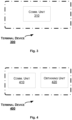
- Fig. 3 is a block diagram of a first terminal device 300 in direct communication with a second terminal device according to an embodiment of the present disclosure.
- the terminal device 300 includes a communication unit 310 configured to transmit to the second terminal device an MCS index, based on which the second terminal device can obtain a modulation order and a TBS in accordance with a first mapping or a second mapping between MCS indices on one hand and modulation orders and TBSs on the other.
- the MCS index is determined by the first terminal device by applying the first or second mapping.
- the second mapping supports a higher modulation order than those supported by the first mapping.
- the first and second mappings have an overlapped portion.
- the overlapped portion is associated with one or more of modulation orders supported by both the first and second mappings.
- the overlapped portion is associated with coding rates below a predefined threshold.
- each TBS associated with the second mapping is scaled down with respect to a corresponding TBS associated with the first mapping by a factor dependent on a number of Resource Elements, REs, available for data transmission.
- the MCS index is determined by the first terminal device by applying the first mapping when retransmission is configured, or the second mapping when no retransmission is configured and a modulation order and a TBS obtained by applying the first mapping would result in a coding rate higher than a predefined threshold.
- the communication unit 310 is further configured to transmit to the second terminal device an indicator indicating which of the first and second mappings is applied by the first terminal device.
- the second terminal device supports the first mapping only.
- the first and second terminal devices are communicating directly with each other on a sidelink for vehicular services.
- the above unit 310 can be implemented as a pure hardware solution or as a combination of software and hardware, e.g., by one or more of: a processor or a micro-processor and adequate software and memory for storing of the software, a Programmable Logic Device (PLD) or other electronic component(s) or processing circuitry configured to perform the actions described above, and illustrated, e.g., in Fig. 1 .
- a processor or a micro-processor and adequate software and memory for storing of the software e.g., a Programmable Logic Device (PLD) or other electronic component(s) or processing circuitry configured to perform the actions described above, and illustrated, e.g., in Fig. 1 .
- PLD Programmable Logic Device
- Fig. 4 is a block diagram of a terminal device 400 (which is referred to as the first terminal device hereafter) in direct communication with a second terminal device according to another embodiment of the present disclosure.
- the terminal device 400 includes a communication unit 410 configured to receive from the second terminal device an MCS index determined by the second terminal device by applying a first mapping or a second mapping between MCS indices on one hand and modulation orders and TBSs on the other.
- the terminal device 400 further includes an obtaining unit 420 configured to obtain, based on the MCS index, a modulation order and a TBS in accordance with the first or second mapping.
- the second mapping supports a higher modulation order than those supported by the first mapping.
- the first and second mappings have an overlapped portion.
- the overlapped portion is associated with one or more of modulation orders supported by both the first and second mappings.
- the overlapped portion is associated with coding rates below a predefined threshold.
- each TBS associated with the second mapping is scaled down with respect to a corresponding TBS associated with the first mapping by a factor dependent on a number of Resource Elements, REs, available for data transmission.
- the modulation order and the TBS are obtained by the first terminal device in accordance with the first mapping when retransmission is configured, or with the second mapping when no retransmission is configured and a modulation order and a TBS obtained in accordance with the first mapping would result in a coding rate higher than a predefined threshold.
- the communication unit 410 is further configured to receive from the second terminal device an indicator indicating which of the first and second mappings is applied by the second terminal device.
- the second terminal device supports the first mapping only.
- the first and second terminal devices are communicating directly with each other on a sidelink for vehicular services.
- the above units 410-420 can be implemented as a pure hardware solution or as a combination of software and hardware, e.g., by one or more of: a processor or a micro-processor and adequate software and memory for storing of the software, a Programmable Logic Device (PLD) or other electronic component(s) or processing circuitry configured to perform the actions described above, and illustrated, e.g., in Fig. 2 .
- PLD Programmable Logic Device
- Fig. 5 is a block diagram of a terminal device 500 according to yet another embodiment of the present disclosure.
- the terminal device 500 (referred to as “the first terminal device") is in direct communication with a second terminal device.
- the terminal device 500 includes a transceiver 510, a processor 520 and a memory 530.
- the memory 530 contains instructions executable by the processor 520 whereby the terminal device 500 is operative to perform the actions, e.g., of the procedure described earlier in conjunction with Fig. 1 .
- the memory 530 contains instructions executable by the processor 520 whereby the terminal device 500 is operative to: transmit to the second terminal device an MCS index, based on which the second terminal device can obtain a modulation order and a TBS in accordance with a first mapping or a second mapping between MCS indices on one hand and modulation orders and TBSs on the other.
- the MCS index is determined by the first terminal device by applying the first or second mapping.
- the second mapping supports a higher modulation order than those supported by the first mapping.
- the first and second mappings have an overlapped portion.
- the overlapped portion is associated with one or more of modulation orders supported by both the first and second mappings.
- the overlapped portion is associated with coding rates below a predefined threshold.
- each TBS associated with the second mapping is scaled down with respect to a corresponding TBS associated with the first mapping by a factor dependent on a number of Resource Elements, REs, available for data transmission.
- the MCS index is determined by the first terminal device by applying the first mapping when retransmission is configured, or the second mapping when no retransmission is configured and a modulation order and a TBS obtained by applying the first mapping would result in a coding rate higher than a predefined threshold.
- the memory 530 further contains instructions executable by the processor 520 whereby the terminal device 500 is operative to transmit to the second terminal device an indicator indicating which of the first and second mappings is applied by the first terminal device.
- the second terminal device supports the first mapping only.
- the first and second terminal devices are communicating directly with each other on a sidelink for vehicular services.
- the memory 530 contains instructions executable by the processor 520 whereby the terminal device 500 is operative to perform the actions, e.g., of the procedure described earlier in conjunction with Fig. 2 .
- the memory 530 contains instructions executable by the processor 520 whereby the terminal device 500 is operative to: receive from the second terminal device an MCS index determined by the second terminal device by applying a first mapping or a second mapping between MCS indices on one hand and modulation orders and TBSs on the other; and obtain, based on the MCS index, a modulation order and a TBS in accordance with the first or second mapping.
- the second mapping supports a higher modulation order than those supported by the first mapping.
- the first and second mappings have an overlapped portion.
- the overlapped portion is associated with one or more of modulation orders supported by both the first and second mappings.
- the overlapped portion is associated with coding rates below a predefined threshold.
- each TBS associated with the second mapping is scaled down with respect to a corresponding TBS associated with the first mapping by a factor dependent on a number of Resource Elements, REs, available for data transmission.
- the modulation order and the TBS are obtained by the first terminal device in accordance with the first mapping when retransmission is configured, or with the second mapping when no retransmission is configured and a modulation order and a TBS obtained in accordance with the first mapping would result in a coding rate higher than a predefined threshold.
- the memory 530 further contains instructions executable by the processor 520 whereby the terminal device 500 is operative to receive from the second terminal device an indicator indicating which of the first and second mappings is applied by the second terminal device.
- the second terminal device supports the first mapping only.
- the first and second terminal devices are communicating directly with each other on a sidelink for vehicular services.
- the present disclosure also provides at least one computer program product in the form of a non-volatile or volatile memory, e.g., a non-transitory computer readable storage medium, an Electrically Erasable Programmable Read-Only Memory (EEPROM), a flash memory and a hard drive.
- the computer program product includes a computer program.
- the computer program includes: code/computer readable instructions, which when executed by the processor 520 causes the terminal device 500 to perform the actions, e.g., of the procedure described earlier in conjunction with Fig. 1 or 2 .
- the computer program product may be configured as a computer program code structured in computer program modules.
- the computer program modules could essentially perform the actions of the flow illustrated in Fig. 1 or 2 .
- the processor may be a single CPU (Central processing unit), but could also comprise two or more processing units.
- the processor may include general purpose microprocessors; instruction set processors and/or related chips sets and/or special purpose microprocessors such as Application Specific Integrated Circuit (ASICs).
- ASICs Application Specific Integrated Circuit
- the processor may also comprise board memory for caching purposes.
- the computer program may be carried by a computer program product connected to the processor.
- the computer program product may comprise a non-transitory computer readable storage medium on which the computer program is stored.
- the computer program product may be a flash memory, a Random-access memory (RAM), a Read-Only Memory (ROM), or an EEPROM, and the computer program modules described above could in alternative embodiments be distributed on different computer program products in the form of memories.
Description
- The present disclosure relates to communication technology, and more particularly, to a terminal device and a method for facilitating direct communication between terminal devices.
- Vehicle to Vehicle/Pedestrian/Infrastructure/Network (V2X) has been standardized in Long Term Evolution (LTE) Release 14. According to the Release 14 standard, only Quadrature Phase Shift Keying (QPSK) and 16 Quadrature Amplitude Modulation (QAM) are supported for sidelink communications. In RAN#75 meeting, a new work item for V2X was approved in RP-170798, New WID on 3GPP V2X Phase 2, 3gpp, March, 2017. One of the objectives in this work item is introduction of 64QAM. That is, Release 15 V2X terminals are required to support 64QAM.
- In the Release 14 V2X, modulation orders and Transport Block Size (TBS) indices are determined from a "Modulation and Coding Scheme (MCS)" field in a Sidelink Control Information (SCI) format. The MCS field contains an MCS index, based on which the corresponding modulation order and TBS can be obtained. The scheme for determining modulation orders and TBSs for Physical Uplink Shared Channel (PUSCH) in the LTE is reused in Physical Sidelink Shared Channel (PSSCH). Table 1 below shows a mapping from MCS indices (IMCS) to modulation orders (Q'm) and TBS indices (ITBS) in the Release 14 V2X.
Table 1 - Mapping from IMCS to Q'm and ITBS for Release 14 V2X MCS Index
I MCSModulation Order

TBS Index
I TBSCoding Rate (no retransmission) 0 2 0 0.10 1 2 1 0.15 2 2 2 0.25 3 2 3 0.31 4 2 4 0.36 5 2 5 0.39 6 2 6 0.44 7 2 7 0.57 8 2 8 0.68 9 2 9 0.79 10 2 10 0.44 11 4 10 0.88 12 4 11 0.51 13 4 12 0.59 14 4 13 0.65 15 4 14 0.73 16 4 15 0.78 17 4 16 0.84 18 4 17 0.92 19 4 18 1.01 20 4 19 1.12 21 4 19 1.12 22 4 20 1.20 23 4 21 1.28 24 4 22 1.40 25 4 23 1.51 26 4 24 1.56 27 4 25 1.62 28 4 26 1.92 29 Reserved 30 31 - Table 1 also shows coding rates corresponding to the modulation orders and TBS indices, with no retransmission assumed. Theoretically, a coding rate higher than one would render a transport block not decodable by a receiver. In practice, a transport block having a coding rate higher than a smaller threshold, e.g., 0.93 as discussed in Release 8, would not be decodable. In either criterion, it can be seen from Table 1 that, for 19≤IMCS ≤28, the coding rates are too high to be decodable at a receiver. In other words, the above Release 14 mapping does not "support" those MCSs in the sense that they are not decodable.
- In order to introduce 64QAM, a straightforward way is to reuse the mapping for PUSCH in LTE, as shown in Table 2 below.
Table 2 - Mapping from IMCS to Q'm and ITBS for PUSCH MCS Index
I MCSModulation Order

TBS Index
I TBSCoding Rate (no retransmission) 0 2 0 0.10 1 2 1 0.15 2 2 2 0.25 3 2 3 0.31 4 2 4 0.36 5 2 5 0.39 6 2 6 0.44 7 2 7 0.57 8 2 8 0.68 9 2 9 0.79 10 2 10 0.44 11 4 10 0.88 12 4 11 0.51 13 4 12 0.59 14 4 13 0.65 15 4 14 0.73 16 4 15 0.78 17 4 16 0.84 18 4 17 0.92 19 4 18 1.01 20 4 19 1.12 21 6 19 0.75 22 6 20 0.80 23 6 21 0.85 24 6 22 0.93 25 6 23 1.01 26 6 24 1.04 27 6 25 1.08 28 6 26 1.28 29 Reserved 30 31 Note: One OFDM symbol is used for the Automatic Gain Control (AGC) settling for QPSK and two for 16QAM/64QAM. - However, as can be seen in Table 2, even with the introduction of 64QAM, for 25≤IMCS ≤28, the coding rates are still too high to be decodable, which would be inefficient for 64QAM transmissions.
- Meanwhile, it is desired that Release 15 V2X terminals should be backward compatible. That is, Release 15 V2X terminals shall co-exist with Release 14 V2X terminals in the same resource pools and use the same scheduling assignment format (which can be decoded by legacy terminals). Eventually, the Release 14 and Release 15 V2X terminals shall be able to communicate with each other directly over sidelink, which requires the Release 14 V2X terminals to be able to decode PSSCH transmitted from the Release 15 V2X terminals, and vice versa.
- Further background information may be found in
United States patent applications US 2015/215068 andUS 2015/036590 ,European patent application EP 2,933969 , and Samsung: "On TBS and soft buffer size" 3GPP Draft; R1-1702862. - It is an object of the present disclosure to provide a terminal device and a method for facilitating direct communication between terminal devices, capable of solving at least one of the above problems.
- According to a first aspect of the present disclosure, a method in a first terminal device for facilitating direct communication with a second terminal device is provided. The method comprises: transmitting to the second terminal device a Modulation and Coding Scheme (MCS) index, based on which the second terminal device can obtain a modulation order and a Transport Block Size (TBS) in accordance with a first mapping or a second mapping between MCS indices on one hand and modulation orders and TBSs on the other. The MCS index is determined by the first terminal device by applying the first or second mapping.
- In an embodiment, the second mapping supports a higher modulation order than those supported by the first mapping.
- In an embodiment, the first and second mappings have an overlapped portion.
- In an embodiment, the overlapped portion is associated with one or more of modulation orders supported by both the first and second mappings.
- In an embodiment, the overlapped portion is associated with coding rates below a predefined threshold.
- In an embodiment, in a portion of the second mapping that does not overlap the first mapping, each TBS associated with the second mapping is scaled down with respect to a corresponding TBS associated with the first mapping by a factor dependent on a number of Resource Elements, REs, available for data transmission.
- In an embodiment, the MCS index is determined by the first terminal device by applying the first mapping when retransmission is configured, or the second mapping when no retransmission is configured and a modulation order and a TBS obtained by applying the first mapping would result in a coding rate higher than a predefined threshold.
- In an embodiment, the method further comprises: transmitting to the second terminal device an indicator indicating which of the first and second mappings is applied by the first terminal device.
- In an embodiment, the second terminal device supports the first mapping only.
- In an embodiment, the first and second terminal devices are communicating directly with each other on a sidelink for vehicular services.
- According to a second aspect of the present disclosure, a method in a first terminal device for facilitating direct communication with a second terminal device is provided. The method comprises: receiving from the second terminal device a Modulation and Coding Scheme (MCS) index determined by the second terminal device by applying a first mapping or a second mapping between MCS indices on one hand and modulation orders and Transport Block Sizes (TBSs) on the other; and obtaining, based on the MCS index, a modulation order and a TBS in accordance with the first or second mapping.
- In an embodiment, the second mapping supports a higher modulation order than those supported by the first mapping.
- In an embodiment, the first and second mappings have an overlapped portion.
- In an embodiment, the overlapped portion is associated with one or more of modulation orders supported by both the first and second mappings.
- In an embodiment, the overlapped portion is associated with coding rates below a predefined threshold.
- In an embodiment, in a portion of the second mapping that does not overlap the first mapping, each TBS associated with the second mapping is scaled down with respect to a corresponding TBS associated with the first mapping by a factor dependent on a number of Resource Elements, REs, available for data transmission.
- In an embodiment, the modulation order and the TBS are obtained by the first terminal device in accordance with the first mapping when retransmission is configured, or with the second mapping when no retransmission is configured and a modulation order and a TBS obtained in accordance with the first mapping would result in a coding rate higher than a predefined threshold.
- In an embodiment, the method further comprises: receiving from the second terminal device an indicator indicating which of the first and second mappings is applied by the second terminal device.
- In an embodiment, the second terminal device supports the first mapping only.
- In an embodiment, the first and second terminal devices are communicating directly with each other on a sidelink for vehicular services.
- According to a third aspect of the present disclosure, a first terminal device in direct communication with a second terminal device is provided. The first terminal device comprises a transceiver, a processor and a memory. The memory comprises instructions which when executed by the processor cause the first terminal device to perform the method according to the above first or second aspect.
- With the embodiments of the present disclosure, two mappings between MCS indices on one hand and modulation orders and TBSs on the other are provided. A terminal device supporting both mappings can apply one of the two mappings, so as to communicate with another terminal device that may support only one mapping. Further, one of the two mappings can be designed to provide higher modulation orders and thus lower but decodable coding rates than the other. In this way, the MCSs can be more efficient.
- The above and other objects, features and advantages will be more apparent from the following description of embodiments with reference to the figures, in which:
-
Fig. 1 is a flowchart illustrating a method for facilitating direct communication between terminals according to an embodiment of the present disclosure; -
Fig. 2 is a flowchart illustrating a method for facilitating direct communication between terminals according to another embodiment of the present disclosure; -
Fig. 3 is a block diagram of a terminal device according to an embodiment of the present disclosure; -
Fig. 4 is a block diagram of a terminal device according to another embodiment of the present disclosure; and -
Fig. 5 is a block diagram of a terminal device according to yet another embodiment of the present disclosure. - The embodiments of the disclosure will be detailed below with reference to the drawings. It should be appreciated that the following embodiments are illustrative only, rather than limiting the scope of the disclosure.
- It shall be understood that although the terms "first" and "second" etc. may be used herein to describe various elements, these elements should not be limited by these terms. These terms are only used to distinguish one element from another. For example, a first element could be termed a second element, and similarly, a second element could be termed a first element, without departing from the scope of example embodiments. As used herein, the term "and/or" includes any and all combinations of one or more of the associated listed terms.
-
Fig. 1 is a flowchart illustrating amethod 100 for facilitating direct communication between terminal devices according to an embodiment of the present disclosure. Themethod 100 can be performed at a first terminal device in direct communication with a second terminal device. The first and second terminal devices can communicate directly with each other on a sidelink for vehicular services. For example, the first terminal device can be a Release 15 V2X terminal as described above and the second terminal device can be a Release 14 or Release 15 V2X terminal. - It can be appreciated by those skilled in the art that the concept of the present disclosure is not limited to Release 14 or Release 15 V2X terminals, but applies generally to scenarios in which new and legacy terminals having different MCSs are in communication with each other. The
method 100 includes the following step. - At step S110, an MCS index is transmitted to the second terminal device. Based on the MCS index, the second terminal device can obtain a modulation order and a TBS in accordance with a first mapping or a second mapping between MCS indices on one hand and modulation orders and TBSs on the other. The MCS index is determined by the first terminal device by applying the first or second mapping.
- Table 3 below shows an example of mappings from MCS indices (IMCS) to modulation orders (Q'm) and TBS indices (ITBS). Table 4 shows corresponding mappings from TBS indices (ITBS) to TBSs (in unit of bits). That is, the mappings between MCS indices and modulation orders are given by Table 3 alone, and the mappings between MCS indices and TBSs are given by Table 3 and Table 4 in combination. In other words, the first mapping described in the step S110 can be obtained from the second and third columns of Table 3 and the second column of Table 4, and the second mapping described in the step S110 can be obtained from the fourth and fifth columns of Table 3 and the third column of Table 4. In Table 4, the number of Physical Resource Blocks (PRBs), denoted as X, can be any valid number for allocated PRBs. Table 4 also shows coding rates of the first and second mappings.
Table 3 - Mapping from IMCS to Q'm and ITBS 1st Mapping 2nd Mapping MCS Index
I MCSModulation Order

TBS Index
I TBSModulation Order

TBS Index
I TBS0 2 0 2 0 1 2 1 2 1 2 2 2 2 2 3 2 3 2 3 4 2 4 2 4 5 2 5 2 5 6 2 6 2 6 7 2 7 2 7 8 2 8 2 8 9 2 9 2 9 10 2 10 2 10 11 4 10 4 10 12 4 11 4 11 13 4 12 4 12 14 4 13 4 13 15 4 14 4 14 16 4 15 4 15 17 4 16 4 16 18 4 17 4 17 19 4 18 4 18 20 4 19 4 19 21 4 19 6 19 22 4 20 6 20 23 4 21 6 21 24 4 22 6 22 25 4 23 6 23 26 4 24 6 24 27 4 25 6 25 28 4 26 6 26 29 Reserved 30 31 Table 4 - Mappings from TBS Indices to TBSs I TBS 1st Mapping 2nd Mapping 1st Mapping 2nd Mapping PRB X X Coding Rate Coding Rate 0 56 56 0.10 0.10 1 88 88 0.15 0.15 2 144 144 0.25 0.25 3 176 176 0.31 0.31 4 208 208 0.36 0.36 5 224 224 0.39 0.39 6 256 256 0.44 0.44 7 328 328 0.57 0.57 8 392 392 0.68 0.68 9 456 456 0.79 0.79 10 504 504 0.44 0.44 11 584 584 0.51 0.51 12 680 680 0.59 0.59 13 744 744 0.65 0.65 14 840 840 0.73 0.73 15 904 904 0.78 0.78 16 968 968 0.84 0.84 17 1064 1064 0.92 0.92 18 1160 1160 1.01 1.01 19 1288 752 1.12 0.65 20 1384 808 1.2 0.47 21 1480 864 1.28 0.50 22 1608 944 1.4 0.54 23 1736 1016 1.51 0.59 24 1800 1056 1.56 0.61 25 1864 1088 1.62 0.63 26 2216 1296 1.92 0.75 - In this example, the second mapping can support a higher modulation order (e.g., 64QAM) than those supported by the first mapping (e.g., QPSK and 16QAM).
- Moreover, in this example, the first and second mappings have an overlapped portion (0≤IMCS ≤20). The overlapped portion is associated with modulation orders supported by both the first and second mappings (i.e., QPSK and 16QAM).
- With the overlapped portion, even if the second terminal device supports the first mapping only and the first terminal device determines the MCS index by applying the second mapping, the second terminal device can have the same understanding of the modulation order and TBS as the first terminal device as long as the determined MCS index is within the overlapped portion.
- In a portion of the second mapping that does not overlap the first mapping (21≤IMCS ≤28), each TBS associated with the second mapping can be scaled down with respect to a corresponding TBS associated with the first mapping by a factor dependent on a number of Resource Elements (REs) (or OFDM symbols) available for data transmission.
- In this example, assuming that 12 OFDM symbols are available for data transmission over PUSCH and 7 over PSSCH, the TBSs in the second mapping can be scaled down by a factor of 7/12 with respect to those in the first mapping (19≤ITBS ≤26). As can be seen from Table 4, for the second mapping, the coding rates for 64QAM (19≤ITBS ≤26) are lower than 0.93 and thus decodable.
- Table 5 below shows another example of mappings from MCS indices (IMCS) to modulation orders (Q'm) and TBS indices (ITBS). Table 6 shows corresponding mappings from TBS indices (ITBS) to TBSs (in unit of bits). Similarly, the first mapping described in the step S110 can be obtained from the second and third columns of Table 5 and the second column of Table 6, and the second mapping described in the step S110 can be obtained from the fourth and fifth columns of Table 5 and the third column of Table 6.
Table 5 -Mapping from IMCS to Q'm and ITBS 1st Mapping 2nd Mapping MCS Index
I MCSModulation Order

TBS Index
I TBSModulation Order

TBS Index
I TBS0 2 0 2 0 1 2 1 2 1 2 2 2 2 2 3 2 3 2 3 4 2 4 2 4 5 2 5 2 5 6 2 6 2 6 7 2 7 2 7 8 2 8 2 8 9 2 9 2 9 10 2 10 2 10 11 4 10 4 10 12 4 11 4 11 13 4 12 4 12 14 4 13 4 13 15 4 14 4 14 16 4 15 4 15 17 4 16 4 16 18 4 17 4 17 19 4 18 4 18 20 4 19 4 19 21 4 19 6 19 22 4 20 6 20 23 4 21 6 21 24 4 22 6 22 25 4 23 6 23 26 4 24 6 24 27 4 25 6 25 28 4 26 6 26 29 Reserved 30 31 Table 6 - Mains from TBS Indices to TBSs ITBS 1st Mapping 2nd Mapping 1st Mapping 2nd Mapping PRB X X Coding Rate Coding Rate 0 56 56 0.10 0.10 1 88 88 0.15 0.15 2 144 144 0.25 0.25 3 176 176 0.31 0.31 4 208 208 0.36 0.36 5 224 224 0.39 0.39 6 256 256 0.44 0.44 7 328 328 0.57 0.57 8 392 392 0.68 0.68 9 456 456 0.79 0.79 10 504 504 0.44 0.44 11 584 584 0.51 0.51 12 680 680 0.59 0.59 13 744 744 0.65 0.65 14 840 840 0.73 0.73 15 904 904 0.78 0.78 16 968 968 0.84 0.84 17 1064 1064 0.92 0.92 18 1160 680 1.01 0.59 19 1288 752 1.12 0.65 20 1384 808 1.2 0.47 21 1480 864 1.28 0.50 22 1608 944 1.4 0.54 23 1736 1016 1.51 0.59 24 1800 1056 1.56 0.61 25 1864 1088 1.62 0.63 26 2216 1296 1.92 0.75 - In the example shown in Table 5 and Table 6, the first and second mappings have an overlapped portion (0≤IMCS ≤18). The overlapped portion is associated with coding rates below a predefined threshold (e.g., 0.93).
- In the example shown in Table 5 and Table 6, in a portion of the second mapping that does not overlap the first mapping (19≤IMCS ≤28), each TBS associated with the second mapping can be scaled down with respect to a corresponding TBS associated with the first mapping by a factor dependent on a number of Resource Elements (REs) (or OFDM symbols) available for data transmission. Again, the factor can be e.g., 7/12.
- Table 7 below shows yet another example of mappings from MCS indices (IMCS) to modulation orders (Q'm) and TBS indices (ITBS). Table 8 shows corresponding mappings from TBS indices (ITBS) to TBSs (in unit of bits). Similarly, the first mapping described in the step S110 can be obtained from the second and third columns of Table 7 and the second column of Table 8, and the second mapping described in the step S110 can be obtained from the fourth and fifth columns of Table 7 and the third column of Table 8. Compared with the previous examples, here the first and second mappings have a smaller overlapped portion (0≤IMCS ≤4).
Table 7 -Mapping from IMCS to Q'm and ITBS 1st Mapping 2nd Mapping MCS Index
I MCSModulation Order

TBS Index I TBS

Modulation Order TBS Index
I TBS0 2 0 2 0 1 2 1 2 1 2 2 2 2 2 3 2 3 2 3 4 2 4 2 4 5 2 5 4 5 6 2 6 4 6 7 2 7 4 7 8 2 8 4 8 9 2 9 4 9 10 2 10 6 10 11 4 10 6 10 12 4 11 6 11 13 4 12 6 12 14 4 13 6 13 15 4 14 6 14 16 4 15 6 15 17 4 16 6 16 18 4 17 6 17 19 4 18 6 18 20 4 19 6 19 21 4 19 6 19 22 4 20 6 20 23 4 21 6 21 24 4 22 6 22 25 4 23 6 23 26 4 24 6 24 27 4 25 6 25 28 4 26 6 26 29 Reserved 30 31 Table 8 - Mains from TBS Indices to TBSs ITBS 1st Mapping 2nd Mapping 1st Mapping 2nd Mapping PRB X X Coding Rate Coding Rate 0 56 56 0.10 0.10 1 88 88 0.15 0.15 2 144 144 0.25 0.25 3 176 176 0.31 0.31 4 208 208 0.36 0.36 5 224 224 0.39 0.20 6 256 256 0.44 0.22 7 328 328 0.57 0.29 8 392 392 0.68 0.34 9 456 456 0.79 0.40 10 504 504 0.44 0.15 11 584 584 0.51 0.34 12 680 680 0.59 0.39 13 744 744 0.65 0.43 14 840 840 0.73 0.49 15 904 904 0.78 0.52 16 968 968 0.84 0.56 17 1064 1064 0.92 0.61 18 1160 680 1.01 0.39 19 1288 752 1.12 0.44 20 1384 808 1.2 0.47 21 1480 864 1.28 0.50 22 1608 944 1.4 0.54 23 1736 1016 1.51 0.59 24 1800 1056 1.56 0.61 25 1864 1088 1.62 0.63 26 2216 1296 1.92 0.75 - In the examples shown in Tables 3~8, it is assumed that no retransmission is configured, as in Tables 1~2. When retransmission is configured, e.g., when one retransmission is provided, Table 1 would become Table 9 below:
Table 9 - Mapping from IMCS to Q'm and ITBS with One Retransmission MCS Index
I MCSModulation Order

TBS Index
I TBSCoding Rate (1 retransmission) 0 2 0 0.05 1 2 1 0.08 2 2 2 0.13 3 2 3 0.16 4 2 4 0.18 5 2 5 0.20 6 2 6 0.22 7 2 7 0.29 8 2 8 0.34 9 2 9 0.40 10 2 10 0.22 11 4 10 0.44 12 4 11 0.26 13 4 12 0.30 14 4 13 0.33 15 4 14 0.37 16 4 15 0.39 17 4 16 0.42 18 4 17 0.46 19 4 18 0.51 20 4 19 0.56 21 4 19 0.56 22 4 20 0.60 23 4 21 0.64 24 4 22 0.70 25 4 23 0.76 26 4 24 0.78 27 4 25 0.81 28 4 26 0.96 29 30 Reserved 31 - As the corresponding mapping from TBS indices (ITBS) to TBSs (in unit of bits), the second column of Table 4 or Table 6 can be reused. It can be seen that, in Table 9, all the MCSs have coding rates lower than 0.93 except for IMCS=28. That is, almost all the MCSs are decodable with one retransmission.
- According to 3GPP TS 36.212 v14.1.1 (2017-01), Section 5.4.3.1.2, the SCI also contains a retransmission index. A terminal device can determine whether retransmission is configured based on this index.
- Accordingly, in the step S110, the MCS index can be determined by the first terminal device by applying the first mapping when retransmission is configured, or the second mapping when no retransmission is configured and a modulation order and a TBS obtained by applying the first mapping would result in a coding rate higher than a predefined threshold (e.g., 0.93). Here, the first mapping may include two portions: a first portion in which each MCS index can be used regardless of whether retransmission is configured, and a second portion in which each MCS index can only be used when retransmission is configured. Accordingly, the second mapping may be the first portion of the first mapping. For example, the first mapping may include MCS indices 0~28 in Table 9 (or a scaled down version thereof), while the second mapping may include MCS indices 0~27 in Table 9 (or the accordingly scaled down version).
- In an example, the
method 100 may further include a step S120 in which the first terminal device transmits to the second terminal device an indicator indicating which of the first and second mappings is applied by the first terminal device. In this way, for example, when the second terminal device is a Release 15 V2X terminal, it can parse the MCS index to obtain the modulation order and the TBS in accordance with the same mapping as applied by the first terminal device. On the other hand, if the second terminal device is e.g., a Release 14 V2X terminal that cannot parse the indicator and/or cannot support the second mapping, it can simply ignore and discard the indicator. -
Fig. 2 is a flowchart illustrating amethod 200 for facilitating direct communication between terminals according to an embodiment of the present disclosure. Themethod 100 can be performed at a first terminal device in direct communication with a second terminal device. The first and second terminal devices can communicate directly with each other on a sidelink for vehicular services. For example, the first terminal device can be a Release 15 V2X terminal as described above and the second terminal device can be a Release 14 or Release 15 V2X terminal. - At step S210, an MCS index is received from the second terminal device. The MCS index is determined by the second terminal device by applying a first mapping or a second mapping between MCS indices on one hand and modulation orders and TBSs on the other.
- In an example, the second mapping can support a higher modulation order (e.g., 64QAM) than those supported by the first mapping (e.g., QPSK and 16QAM).
- In an example, the first and second mappings can have an overlapped portion. The overlapped portion can be associated with one or more of modulation orders supported by both the first and second mappings. Additionally or alternatively, the overlapped portion can be associated with coding rates below a predefined threshold (e.g., 0.93). In a portion of the second mapping that does not overlap the first mapping, each TBS associated with the second mapping is scaled down with respect to a corresponding TBS associated with the first mapping by a factor dependent on a number of REs or OFDM symbols available for data transmission.
- At step S220, a modulation order and a TBS are obtained based on the MCS index in accordance with the first or second mapping.
- In the step S220, the modulation order and the TBS can be obtained by the first terminal device in accordance with the first mapping when retransmission is configured, or with the second mapping when no retransmission is configured and a modulation order and a TBS obtained in accordance with the first mapping would result in a coding rate higher than a predefined threshold (e.g., 0.93).
- In an example, the second terminal device may support the first mapping only.
- In an example, the
method 200 may further include a step S230 in which the first terminal device receives from the second terminal device an indicator indicating which of the first and second mappings is applied by the second terminal device. - The examples described above in connection with
Fig. 1 and themethod 100, especially those related to Tables 3~9, are applicable to themethod 200. - Correspondingly to the
method 100 as described above, a terminal device is provided.Fig. 3 is a block diagram of a firstterminal device 300 in direct communication with a second terminal device according to an embodiment of the present disclosure. - As shown in
Fig. 3 , theterminal device 300 includes acommunication unit 310 configured to transmit to the second terminal device an MCS index, based on which the second terminal device can obtain a modulation order and a TBS in accordance with a first mapping or a second mapping between MCS indices on one hand and modulation orders and TBSs on the other. The MCS index is determined by the first terminal device by applying the first or second mapping. - In an embodiment, the second mapping supports a higher modulation order than those supported by the first mapping.
- In an embodiment, the first and second mappings have an overlapped portion.
- In an embodiment, the overlapped portion is associated with one or more of modulation orders supported by both the first and second mappings.
- In an embodiment, the overlapped portion is associated with coding rates below a predefined threshold.
- In an embodiment, in a portion of the second mapping that does not overlap the first mapping, each TBS associated with the second mapping is scaled down with respect to a corresponding TBS associated with the first mapping by a factor dependent on a number of Resource Elements, REs, available for data transmission.
- In an embodiment, the MCS index is determined by the first terminal device by applying the first mapping when retransmission is configured, or the second mapping when no retransmission is configured and a modulation order and a TBS obtained by applying the first mapping would result in a coding rate higher than a predefined threshold.
- In an embodiment, the
communication unit 310 is further configured to transmit to the second terminal device an indicator indicating which of the first and second mappings is applied by the first terminal device. - In an embodiment, the second terminal device supports the first mapping only.
- In an embodiment, the first and second terminal devices are communicating directly with each other on a sidelink for vehicular services.
- The
above unit 310 can be implemented as a pure hardware solution or as a combination of software and hardware, e.g., by one or more of: a processor or a micro-processor and adequate software and memory for storing of the software, a Programmable Logic Device (PLD) or other electronic component(s) or processing circuitry configured to perform the actions described above, and illustrated, e.g., inFig. 1 . - Correspondingly to the
method 200 as described above, a terminal device is provided.Fig. 4 is a block diagram of a terminal device 400 (which is referred to as the first terminal device hereafter) in direct communication with a second terminal device according to another embodiment of the present disclosure. - As shown in
Fig. 4 , theterminal device 400 includes acommunication unit 410 configured to receive from the second terminal device an MCS index determined by the second terminal device by applying a first mapping or a second mapping between MCS indices on one hand and modulation orders and TBSs on the other. Theterminal device 400 further includes an obtainingunit 420 configured to obtain, based on the MCS index, a modulation order and a TBS in accordance with the first or second mapping. - In an embodiment, the second mapping supports a higher modulation order than those supported by the first mapping.
- In an embodiment, the first and second mappings have an overlapped portion.
- In an embodiment, the overlapped portion is associated with one or more of modulation orders supported by both the first and second mappings.
- In an embodiment, the overlapped portion is associated with coding rates below a predefined threshold.
- In an embodiment, in a portion of the second mapping that does not overlap the first mapping, each TBS associated with the second mapping is scaled down with respect to a corresponding TBS associated with the first mapping by a factor dependent on a number of Resource Elements, REs, available for data transmission.
- In an embodiment, the modulation order and the TBS are obtained by the first terminal device in accordance with the first mapping when retransmission is configured, or with the second mapping when no retransmission is configured and a modulation order and a TBS obtained in accordance with the first mapping would result in a coding rate higher than a predefined threshold.
- In an embodiment, the
communication unit 410 is further configured to receive from the second terminal device an indicator indicating which of the first and second mappings is applied by the second terminal device. - In an embodiment, the second terminal device supports the first mapping only.
- In an embodiment, the first and second terminal devices are communicating directly with each other on a sidelink for vehicular services.
- The above units 410-420 can be implemented as a pure hardware solution or as a combination of software and hardware, e.g., by one or more of: a processor or a micro-processor and adequate software and memory for storing of the software, a Programmable Logic Device (PLD) or other electronic component(s) or processing circuitry configured to perform the actions described above, and illustrated, e.g., in
Fig. 2 . -
Fig. 5 is a block diagram of aterminal device 500 according to yet another embodiment of the present disclosure. The terminal device 500 (referred to as "the first terminal device") is in direct communication with a second terminal device. - The
terminal device 500 includes atransceiver 510, aprocessor 520 and amemory 530. Thememory 530 contains instructions executable by theprocessor 520 whereby theterminal device 500 is operative to perform the actions, e.g., of the procedure described earlier in conjunction withFig. 1 . Particularly, thememory 530 contains instructions executable by theprocessor 520 whereby theterminal device 500 is operative to: transmit to the second terminal device an MCS index, based on which the second terminal device can obtain a modulation order and a TBS in accordance with a first mapping or a second mapping between MCS indices on one hand and modulation orders and TBSs on the other. The MCS index is determined by the first terminal device by applying the first or second mapping. - In an embodiment, the second mapping supports a higher modulation order than those supported by the first mapping.
- In an embodiment, the first and second mappings have an overlapped portion.
- In an embodiment, the overlapped portion is associated with one or more of modulation orders supported by both the first and second mappings.
- In an embodiment, the overlapped portion is associated with coding rates below a predefined threshold.
- In an embodiment, in a portion of the second mapping that does not overlap the first mapping, each TBS associated with the second mapping is scaled down with respect to a corresponding TBS associated with the first mapping by a factor dependent on a number of Resource Elements, REs, available for data transmission.
- In an embodiment, the MCS index is determined by the first terminal device by applying the first mapping when retransmission is configured, or the second mapping when no retransmission is configured and a modulation order and a TBS obtained by applying the first mapping would result in a coding rate higher than a predefined threshold.
- In an embodiment, the
memory 530 further contains instructions executable by theprocessor 520 whereby theterminal device 500 is operative to transmit to the second terminal device an indicator indicating which of the first and second mappings is applied by the first terminal device. - In an embodiment, the second terminal device supports the first mapping only.
- In an embodiment, the first and second terminal devices are communicating directly with each other on a sidelink for vehicular services.
- Additionally or alternatively, the
memory 530 contains instructions executable by theprocessor 520 whereby theterminal device 500 is operative to perform the actions, e.g., of the procedure described earlier in conjunction withFig. 2 . Particularly, thememory 530 contains instructions executable by theprocessor 520 whereby theterminal device 500 is operative to: receive from the second terminal device an MCS index determined by the second terminal device by applying a first mapping or a second mapping between MCS indices on one hand and modulation orders and TBSs on the other; and obtain, based on the MCS index, a modulation order and a TBS in accordance with the first or second mapping. - In an embodiment, the second mapping supports a higher modulation order than those supported by the first mapping.
- In an embodiment, the first and second mappings have an overlapped portion.
- In an embodiment, the overlapped portion is associated with one or more of modulation orders supported by both the first and second mappings.
- In an embodiment, the overlapped portion is associated with coding rates below a predefined threshold.
- In an embodiment, in a portion of the second mapping that does not overlap the first mapping, each TBS associated with the second mapping is scaled down with respect to a corresponding TBS associated with the first mapping by a factor dependent on a number of Resource Elements, REs, available for data transmission.
- In an embodiment, the modulation order and the TBS are obtained by the first terminal device in accordance with the first mapping when retransmission is configured, or with the second mapping when no retransmission is configured and a modulation order and a TBS obtained in accordance with the first mapping would result in a coding rate higher than a predefined threshold.
- In an embodiment, the
memory 530 further contains instructions executable by theprocessor 520 whereby theterminal device 500 is operative to receive from the second terminal device an indicator indicating which of the first and second mappings is applied by the second terminal device. - In an embodiment, the second terminal device supports the first mapping only.
- In an embodiment, the first and second terminal devices are communicating directly with each other on a sidelink for vehicular services.
- The present disclosure also provides at least one computer program product in the form of a non-volatile or volatile memory, e.g., a non-transitory computer readable storage medium, an Electrically Erasable Programmable Read-Only Memory (EEPROM), a flash memory and a hard drive. The computer program product includes a computer program. The computer program includes: code/computer readable instructions, which when executed by the
processor 520 causes theterminal device 500 to perform the actions, e.g., of the procedure described earlier in conjunction withFig. 1 or 2 . - The computer program product may be configured as a computer program code structured in computer program modules. The computer program modules could essentially perform the actions of the flow illustrated in
Fig. 1 or 2 . - The processor may be a single CPU (Central processing unit), but could also comprise two or more processing units. For example, the processor may include general purpose microprocessors; instruction set processors and/or related chips sets and/or special purpose microprocessors such as Application Specific Integrated Circuit (ASICs). The processor may also comprise board memory for caching purposes. The computer program may be carried by a computer program product connected to the processor. The computer program product may comprise a non-transitory computer readable storage medium on which the computer program is stored. For example, the computer program product may be a flash memory, a Random-access memory (RAM), a Read-Only Memory (ROM), or an EEPROM, and the computer program modules described above could in alternative embodiments be distributed on different computer program products in the form of memories.
- The disclosure has been described above with reference to embodiments thereof. It should be understood that various modifications, alternations and additions can be made by those skilled in the art without departing from the scope of the disclosure. Therefore, the scope of the disclosure is not limited to the above particular embodiments but only defined by the claims as attached.
Claims (17)
- A method (100) in a first terminal device for facilitating direct communication with a second terminal device, comprising:- transmitting (S110) to the second terminal device a Modulation and Coding Scheme, MCS, index, based on which the second terminal device can obtain a modulation order and a Transport Block Size, TBS, in accordance with a first mapping or a second mapping between MCS indices on one hand and modulation orders and TBSs on the other,wherein the MCS index is determined by the first terminal device by applying the first or second mapping.
- The method (100) of claim 1, wherein the second mapping supports a higher modulation order than those supported by the first mapping.
- The method (100) of claim 1 or 2, wherein the first and second mappings have an overlapped portion.
- The method (100) of claim 3, wherein the overlapped portion is associated with one or more of modulation orders supported by both the first and second mappings.
- The method (100) of claim 3 or 4, wherein the overlapped portion is associated with coding rates below a predefined threshold.
- The method (100) of claim 5, wherein, in a portion of the second mapping that does not overlap the first mapping, each TBS associated with the second mapping is scaled down with respect to a corresponding TBS associated with the first mapping by a factor dependent on a number of Resource Elements, REs, available for data transmission.
- The method (100) of any of claims 1-6, wherein the MCS index is determined by the first terminal device by applying the first mapping when retransmission is configured, or the second mapping when no retransmission is configured and a modulation order and a TBS obtained by applying the first mapping would result in a coding rate higher than a predefined threshold.
- The method (100) of any of claims 1-7, further comprising:- transmitting (S120) to the second terminal device an indicator indicating which of the first and second mappings is applied by the first terminal device.
- The method (100) of any of claims 1-8, wherein the second terminaldevice supports the first mapping only; and/ or
wherein the first and second terminal devices are communicating directly witheach other on a sidelink for vehicular services. - A method (200) in a first terminal device for facilitating direct communication with a second terminal device, comprising:- receiving (S210) from the second terminal device a Modulation and Coding Scheme, MCS, index determined by the second terminal device by applying a first mapping or a second mapping between MCS indices on one hand and modulation orders and Transport Block Sizes, TBSs, on the other; and- obtaining (S220), based on the MCS index, a modulation order and a TBS in accordance with the first or second mapping.
- The method (200) of claim 10, wherein the second mapping supports a higher modulation order than those supported by the first mapping.
- The method (200) of claim 10 or 11, wherein the first and second mappings have an overlapped portion.
- The method (200) of claim 12, wherein the overlapped portion is associated with one or more of modulation orders supported by both the first and second mappings.
- The method (200) of claim 12 or 13, wherein the overlapped portion is associated with coding rates below a predefined threshold.
- The method (200) of claim 14, wherein, in a portion of the second mapping that does not overlap the first mapping, each TBS associated with the second mapping is scaled down with respect to a corresponding TBS associated with the first mapping by a factor dependent on a number of Resource Elements, REs, available for data transmission.
- The method (200) of any of claims 10-15, wherein
the modulation order and the TBS are obtained by the first terminal device in accordance with the first mapping when retransmission is configured, or with the second mapping when no retransmission is configured and a modulation order and a TBS obtained in accordance with the first mapping would result in a coding rate higher than a predefined threshold; and wherein the method (200) further comprises:- receiving (S230) from the second terminal device an indicator indicating which of the first and second mappings is applied by the second terminal device. - A first terminal device (500) in direct communication with a second terminal device, comprising a transceiver (510), a processor (520) and a memory (530), the memory (510) comprising instructions which when executed by the processor (520) cause the first terminal device (500) to perform the method (100; 200) according to any of claims 1-16.
Applications Claiming Priority (3)
| Application Number | Priority Date | Filing Date | Title |
|---|---|---|---|
| CN2017078070 | 2017-03-24 | ||
| EP18772455.4A EP3568962B1 (en) | 2017-03-24 | 2018-03-23 | Terminal device and method for facilitating communication between terminal devices |
| PCT/CN2018/080203 WO2018171716A1 (en) | 2017-03-24 | 2018-03-23 | Terminal device and method for facilitating communication between terminal devices |
Related Parent Applications (2)
| Application Number | Title | Priority Date | Filing Date |
|---|---|---|---|
| EP18772455.4A Division EP3568962B1 (en) | 2017-03-24 | 2018-03-23 | Terminal device and method for facilitating communication between terminal devices |
| EP18772455.4A Division-Into EP3568962B1 (en) | 2017-03-24 | 2018-03-23 | Terminal device and method for facilitating communication between terminal devices |
Publications (3)
| Publication Number | Publication Date |
|---|---|
| EP3962013A1 EP3962013A1 (en) | 2022-03-02 |
| EP3962013B1 true EP3962013B1 (en) | 2023-10-25 |
| EP3962013C0 EP3962013C0 (en) | 2023-10-25 |
Family
ID=63586222
Family Applications (2)
| Application Number | Title | Priority Date | Filing Date |
|---|---|---|---|
| EP18772455.4A Active EP3568962B1 (en) | 2017-03-24 | 2018-03-23 | Terminal device and method for facilitating communication between terminal devices |
| EP21190966.8A Active EP3962013B1 (en) | 2017-03-24 | 2018-03-23 | Terminal device and method for facilitating communication between terminal devices |
Family Applications Before (1)
| Application Number | Title | Priority Date | Filing Date |
|---|---|---|---|
| EP18772455.4A Active EP3568962B1 (en) | 2017-03-24 | 2018-03-23 | Terminal device and method for facilitating communication between terminal devices |
Country Status (4)
| Country | Link |
|---|---|
| US (2) | US11296815B2 (en) |
| EP (2) | EP3568962B1 (en) |
| BR (1) | BR112019019476A2 (en) |
| WO (1) | WO2018171716A1 (en) |
Families Citing this family (8)
| Publication number | Priority date | Publication date | Assignee | Title |
|---|---|---|---|---|
| WO2018171716A1 (en) | 2017-03-24 | 2018-09-27 | Telefonaktiebolaget Lm Ericsson (Publ) | Terminal device and method for facilitating communication between terminal devices |
| CN108964831B (en) * | 2017-05-18 | 2023-11-17 | 华为技术有限公司 | Signal transmission method and device |
| US11564070B2 (en) * | 2017-10-06 | 2023-01-24 | Qualcomm Incorporated | Vehicle to everything (V2X) radio access technology (RAT) feature negotiation and control |
| CN109714827B (en) * | 2017-10-26 | 2023-09-01 | 华为技术有限公司 | Uplink control information transmission method and device |
| WO2019183903A1 (en) * | 2018-03-29 | 2019-10-03 | Oppo广东移动通信有限公司 | Method for transmitting data and terminal device |
| US11722241B2 (en) * | 2018-04-12 | 2023-08-08 | Qualcomm Incorporated | Transport block size determination for a transmission time interval |
| US11689314B2 (en) * | 2019-08-14 | 2023-06-27 | Qualcomm Incorporated | Flexible implicit modulation and coding scheme indication |
| KR20210123993A (en) * | 2020-04-03 | 2021-10-14 | 삼성전자주식회사 | Method and apparatus for transmission and reception of data in communication system |
Family Cites Families (11)
| Publication number | Priority date | Publication date | Assignee | Title |
|---|---|---|---|---|
| KR101643634B1 (en) * | 2012-02-20 | 2016-07-29 | 노키아 솔루션스 앤드 네트웍스 오와이 | Controlling a modulation and coding scheme for a transmission between a base station and a user equipment |
| US9419772B2 (en) * | 2012-12-17 | 2016-08-16 | Lg Electronics Inc. | Method and apparatus for transmitting and receiving MCS index for 256QAM in wireless access system |
| CN103944855B (en) | 2013-01-18 | 2018-08-17 | 中兴通讯股份有限公司 | modulation processing method and device |
| KR20210021092A (en) * | 2013-08-07 | 2021-02-24 | 인터디지탈 패튼 홀딩스, 인크 | Distributed scheduling for device-to-device communication |
| US20150215068A1 (en) | 2014-01-29 | 2015-07-30 | Htc Corporation | Method of Selecting Modulation and Transport Block Size Index Table |
| KR101632354B1 (en) * | 2014-03-21 | 2016-06-22 | 주식회사 케이티 | Methods for transmitting and receiving the downlink control information and Apparatuses thereof |
| KR20150134908A (en) | 2014-05-23 | 2015-12-02 | 삼성전자주식회사 | Method and apparatus for transmission and reception of low-cost terminal in wireless communication system |
| EP3806378A1 (en) * | 2015-08-14 | 2021-04-14 | Sun Patent Trust | Modulation order adaptation for partial subframes |
| CN108023666B (en) * | 2016-11-03 | 2020-07-28 | 华为技术有限公司 | Method and apparatus for wireless communication |
| CN109923882B (en) * | 2016-11-15 | 2021-08-20 | Lg 电子株式会社 | Signal transmission method for V2X communication in wireless communication system and apparatus therefor |
| WO2018171716A1 (en) | 2017-03-24 | 2018-09-27 | Telefonaktiebolaget Lm Ericsson (Publ) | Terminal device and method for facilitating communication between terminal devices |
-
2018
- 2018-03-23 WO PCT/CN2018/080203 patent/WO2018171716A1/en active Search and Examination
- 2018-03-23 EP EP18772455.4A patent/EP3568962B1/en active Active
- 2018-03-23 US US16/496,938 patent/US11296815B2/en active Active
- 2018-03-23 BR BR112019019476A patent/BR112019019476A2/en unknown
- 2018-03-23 EP EP21190966.8A patent/EP3962013B1/en active Active
-
2022
- 2022-04-04 US US17/657,950 patent/US11817948B2/en active Active
Also Published As
| Publication number | Publication date |
|---|---|
| EP3962013A1 (en) | 2022-03-02 |
| US20220231782A1 (en) | 2022-07-21 |
| US20200136746A1 (en) | 2020-04-30 |
| US11296815B2 (en) | 2022-04-05 |
| WO2018171716A1 (en) | 2018-09-27 |
| BR112019019476A2 (en) | 2020-04-22 |
| EP3568962B1 (en) | 2021-09-15 |
| EP3568962A4 (en) | 2020-02-26 |
| EP3962013C0 (en) | 2023-10-25 |
| EP3568962A1 (en) | 2019-11-20 |
| US11817948B2 (en) | 2023-11-14 |
Similar Documents
| Publication | Publication Date | Title |
|---|---|---|
| EP3962013B1 (en) | Terminal device and method for facilitating communication between terminal devices | |
| EP2340630B1 (en) | Efficient transmission and reception of feedback data and user data | |
| EP3755089B1 (en) | Downlink control information (dci) transmission method and device | |
| EP3493437A1 (en) | Hybrid automatic repeat request acknowledgement (harq-ack) feedback method and apparatus | |
| TWI426730B (en) | Apparatus, method and computer program product providing partitioned downlink shared control channel having fixed and variable component parts | |
| EP3288328B1 (en) | Method and apparatus for encoding uplink control information | |
| US11690050B2 (en) | Hybrid automatic repeat request-acknowledgement (HARQ-ACK) information transmission via physical uplink shared channel (PUSCH) | |
| CN110391870B (en) | Method and device for rate matching, and method and device for rate de-matching | |
| EP3716518B1 (en) | Channel state information transmission method, communication device, and apparatus | |
| US8532017B2 (en) | TPC command signaling in DL control channel identifying the target and limiting blind decoding | |
| CN109644177A (en) | Wireless communication transceiver and wireless communications method | |
| US11375479B2 (en) | Data transmission method, communications device, and network device | |
| US20120207108A1 (en) | Methods and Nodes Related to Coding of Channel Status Information (CSI) Payload | |
| WO2019056369A1 (en) | Communication method and device | |
| EP3573395A1 (en) | Communication method and device | |
| CN107409381B (en) | Method for assisting data transmission on a first carrier by indicating a termination point of the data transmission | |
| EP4017171A1 (en) | Transmission device, reception device, transmission method, and reception method | |
| US20180323911A1 (en) | Device and Method of Handling a Code Block Group Retransmission | |
| EP3203671B1 (en) | Device and method of handling uplink transmission | |
| EP3739997B1 (en) | Method and device for determining cap of transmission resources available for control information, and communication apparatus | |
| EP3145231B1 (en) | Data transmission method, base station and user equipment | |
| EP3817475A1 (en) | Transmission method, apparatus, and system | |
| CN108809531B (en) | Data transmission method, terminal and base station | |
| KR101232352B1 (en) | Apparatus and method for ack channel allocation in orthogonal frequency division multiple access system | |
| CN111355562B (en) | Data transmission method and communication device |
Legal Events
| Date | Code | Title | Description |
|---|---|---|---|
| PUAI | Public reference made under article 153(3) epc to a published international application that has entered the european phase |
Free format text: ORIGINAL CODE: 0009012 |
|
| STAA | Information on the status of an ep patent application or granted ep patent |
Free format text: STATUS: REQUEST FOR EXAMINATION WAS MADE |
|
| 17P | Request for examination filed |
Effective date: 20210812 |
|
| AC | Divisional application: reference to earlier application |
Ref document number: 3568962 Country of ref document: EP Kind code of ref document: P |
|
| AK | Designated contracting states |
Kind code of ref document: A1 Designated state(s): AL AT BE BG CH CY CZ DE DK EE ES FI FR GB GR HR HU IE IS IT LI LT LU LV MC MK MT NL NO PL PT RO RS SE SI SK SM TR |
|
| REG | Reference to a national code |
Ref country code: DE Ref legal event code: R079 Ref document number: 602018060237 Country of ref document: DE Free format text: PREVIOUS MAIN CLASS: H04L0027340000 Ipc: H04L0001186700 Ref country code: DE Ref legal event code: R079 Free format text: PREVIOUS MAIN CLASS: H04L0027340000 Ipc: H04L0001186700 |
|
| GRAP | Despatch of communication of intention to grant a patent |
Free format text: ORIGINAL CODE: EPIDOSNIGR1 |
|
| STAA | Information on the status of an ep patent application or granted ep patent |
Free format text: STATUS: GRANT OF PATENT IS INTENDED |
|
| RIC1 | Information provided on ipc code assigned before grant |
Ipc: H04L 1/00 20060101ALI20230414BHEP Ipc: H04W 92/18 20090101ALI20230414BHEP Ipc: H04L 27/34 20060101ALI20230414BHEP Ipc: H04L 1/1867 20230101AFI20230414BHEP |
|
| INTG | Intention to grant announced |
Effective date: 20230522 |
|
| GRAS | Grant fee paid |
Free format text: ORIGINAL CODE: EPIDOSNIGR3 |
|
| GRAA | (expected) grant |
Free format text: ORIGINAL CODE: 0009210 |
|
| STAA | Information on the status of an ep patent application or granted ep patent |
Free format text: STATUS: THE PATENT HAS BEEN GRANTED |
|
| AC | Divisional application: reference to earlier application |
Ref document number: 3568962 Country of ref document: EP Kind code of ref document: P |
|
| AK | Designated contracting states |
Kind code of ref document: B1 Designated state(s): AL AT BE BG CH CY CZ DE DK EE ES FI FR GB GR HR HU IE IS IT LI LT LU LV MC MK MT NL NO PL PT RO RS SE SI SK SM TR |
|
| REG | Reference to a national code |
Ref country code: GB Ref legal event code: FG4D |
|
| REG | Reference to a national code |
Ref country code: CH Ref legal event code: EP |
|
| REG | Reference to a national code |
Ref country code: DE Ref legal event code: R096 Ref document number: 602018060237 Country of ref document: DE |
|
| REG | Reference to a national code |
Ref country code: IE Ref legal event code: FG4D |
|
| U01 | Request for unitary effect filed |
Effective date: 20231025 |
|
| U07 | Unitary effect registered |
Designated state(s): AT BE BG DE DK EE FI FR IT LT LU LV MT NL PT SE SI Effective date: 20231030 |
|
| PG25 | Lapsed in a contracting state [announced via postgrant information from national office to epo] |
Ref country code: GR Free format text: LAPSE BECAUSE OF FAILURE TO SUBMIT A TRANSLATION OF THE DESCRIPTION OR TO PAY THE FEE WITHIN THE PRESCRIBED TIME-LIMIT Effective date: 20240126 |
|
| PG25 | Lapsed in a contracting state [announced via postgrant information from national office to epo] |
Ref country code: IS Free format text: LAPSE BECAUSE OF FAILURE TO SUBMIT A TRANSLATION OF THE DESCRIPTION OR TO PAY THE FEE WITHIN THE PRESCRIBED TIME-LIMIT Effective date: 20240225 |