EP3962012A1 - System und verfahren für präambeln in einem drahtloskommunikationsnetzwerk - Google Patents
System und verfahren für präambeln in einem drahtloskommunikationsnetzwerk Download PDFInfo
- Publication number
- EP3962012A1 EP3962012A1 EP21186081.2A EP21186081A EP3962012A1 EP 3962012 A1 EP3962012 A1 EP 3962012A1 EP 21186081 A EP21186081 A EP 21186081A EP 3962012 A1 EP3962012 A1 EP 3962012A1
- Authority
- EP
- European Patent Office
- Prior art keywords
- field
- long training
- frame
- beamformed
- training field
- Prior art date
- Legal status (The legal status is an assumption and is not a legal conclusion. Google has not performed a legal analysis and makes no representation as to the accuracy of the status listed.)
- Pending
Links
Images


Classifications
-
- H—ELECTRICITY
- H04—ELECTRIC COMMUNICATION TECHNIQUE
- H04L—TRANSMISSION OF DIGITAL INFORMATION, e.g. TELEGRAPHIC COMMUNICATION
- H04L27/00—Modulated-carrier systems
- H04L27/26—Systems using multi-frequency codes
- H04L27/2601—Multicarrier modulation systems
- H04L27/2602—Signal structure
- H04L27/261—Details of reference signals
- H04L27/2613—Structure of the reference signals
-
- H—ELECTRICITY
- H04—ELECTRIC COMMUNICATION TECHNIQUE
- H04B—TRANSMISSION
- H04B7/00—Radio transmission systems, i.e. using radiation field
- H04B7/02—Diversity systems; Multi-antenna system, i.e. transmission or reception using multiple antennas
- H04B7/04—Diversity systems; Multi-antenna system, i.e. transmission or reception using multiple antennas using two or more spaced independent antennas
- H04B7/06—Diversity systems; Multi-antenna system, i.e. transmission or reception using multiple antennas using two or more spaced independent antennas at the transmitting station
- H04B7/0613—Diversity systems; Multi-antenna system, i.e. transmission or reception using multiple antennas using two or more spaced independent antennas at the transmitting station using simultaneous transmission
- H04B7/0615—Diversity systems; Multi-antenna system, i.e. transmission or reception using multiple antennas using two or more spaced independent antennas at the transmitting station using simultaneous transmission of weighted versions of same signal
- H04B7/0617—Diversity systems; Multi-antenna system, i.e. transmission or reception using multiple antennas using two or more spaced independent antennas at the transmitting station using simultaneous transmission of weighted versions of same signal for beam forming
-
- H—ELECTRICITY
- H04—ELECTRIC COMMUNICATION TECHNIQUE
- H04B—TRANSMISSION
- H04B7/00—Radio transmission systems, i.e. using radiation field
- H04B7/02—Diversity systems; Multi-antenna system, i.e. transmission or reception using multiple antennas
- H04B7/04—Diversity systems; Multi-antenna system, i.e. transmission or reception using multiple antennas using two or more spaced independent antennas
- H04B7/06—Diversity systems; Multi-antenna system, i.e. transmission or reception using multiple antennas using two or more spaced independent antennas at the transmitting station
- H04B7/0686—Hybrid systems, i.e. switching and simultaneous transmission
- H04B7/0689—Hybrid systems, i.e. switching and simultaneous transmission using different transmission schemes, at least one of them being a diversity transmission scheme
-
- H—ELECTRICITY
- H04—ELECTRIC COMMUNICATION TECHNIQUE
- H04L—TRANSMISSION OF DIGITAL INFORMATION, e.g. TELEGRAPHIC COMMUNICATION
- H04L5/00—Arrangements affording multiple use of the transmission path
- H04L5/003—Arrangements for allocating sub-channels of the transmission path
- H04L5/0048—Allocation of pilot signals, i.e. of signals known to the receiver
-
- H—ELECTRICITY
- H04—ELECTRIC COMMUNICATION TECHNIQUE
- H04L—TRANSMISSION OF DIGITAL INFORMATION, e.g. TELEGRAPHIC COMMUNICATION
- H04L69/00—Network arrangements, protocols or services independent of the application payload and not provided for in the other groups of this subclass
- H04L69/22—Parsing or analysis of headers
-
- H—ELECTRICITY
- H04—ELECTRIC COMMUNICATION TECHNIQUE
- H04W—WIRELESS COMMUNICATION NETWORKS
- H04W28/00—Network traffic management; Network resource management
- H04W28/02—Traffic management, e.g. flow control or congestion control
- H04W28/06—Optimizing the usage of the radio link, e.g. header compression, information sizing, discarding information
-
- H—ELECTRICITY
- H04—ELECTRIC COMMUNICATION TECHNIQUE
- H04L—TRANSMISSION OF DIGITAL INFORMATION, e.g. TELEGRAPHIC COMMUNICATION
- H04L5/00—Arrangements affording multiple use of the transmission path
- H04L5/003—Arrangements for allocating sub-channels of the transmission path
- H04L5/0053—Allocation of signaling, i.e. of overhead other than pilot signals
-
- H—ELECTRICITY
- H04—ELECTRIC COMMUNICATION TECHNIQUE
- H04W—WIRELESS COMMUNICATION NETWORKS
- H04W84/00—Network topologies
- H04W84/02—Hierarchically pre-organised networks, e.g. paging networks, cellular networks, WLAN [Wireless Local Area Network] or WLL [Wireless Local Loop]
- H04W84/10—Small scale networks; Flat hierarchical networks
- H04W84/12—WLAN [Wireless Local Area Networks]
Definitions
- the present disclosure relates generally to digital communications, and more particularly to a system and method for preambles in a wireless communications network.
- IEEE 802.11 is a set of standards for implementing wireless local area network (WLAN).
- the preamble part is usually composed of three fields: a short training field (STF), a long training field (LTF), and a signal field (SIG).
- STF short training field
- LTF long training field
- SIG signal field
- the STF is used for coarse synchronization, automatic gain control (AGC), and the like.
- the LTF is used for channel estimation, fine synchronization, etc.
- the SIG is used to indicate the information of the frame; rate, length, and the like.
- IEEE 802.11 WLAN technology evolves, a preamble design for IEEE 802.11ah is needed for its own network environment.
- Example embodiments of the present disclosure which provide a system and method for preambles in a wireless communications network.
- a method for method for transmitting a frame includes generating, by an access point, an omni portion of the frame, the omni portion including a non-beamformed long training field and a signal field, the non-beamformed long training field including channel estimation information used to decode the signal field, the non-beamformed long training field configured to be transmitted through one of multiple antennas and multiple streams.
- the method also includes generating, by the access point, a multi-stream portion of the frame, the multi-stream portion including a data field and a multi-stream long training field, the multi-stream long training field including station-specific decoding information for station-specific data in the data field.
- the method further includes applying, by the access point, a beamforming indicator to the signal field of the omni portion, and transmitting, by the access point, the frame.
- a method for receiving a frame includes receiving, by a station, an omni portion of the frame, the omni portion includes a non-beamformed long training field and a signal field, the non-beamformed long training field including channel estimation information used to decode the signal field.
- the method also includes determining, by the station, a beamform status of a multi-stream portion of the frame, and receiving, by the station, the multi-stream portion of the frame, the multi-stream portion including a multi-stream long training field and a data field, the multi-stream long training field including station-specific decoding information for station-specific data in the data field.
- the method further includes decoding, by the station, the multi-stream portion of the frame using a technique commensurate with the beamform status of the multi-stream portion of the frame.
- a transmitting device in accordance with another example embodiment of the present disclosure, includes a processor, and a transmitter operatively coupled to the processor.
- the processor generates an omni portion of a frame, the omni portion including a non-beamformed long training field and a signal field, the non-beamformed long training field including channel estimation information used to decode the signal field, the non-beamformed long training field to be transmitted through one of multiple antennas and multiple streams.
- the processor generates a multi-stream portion of the frame, the multi-stream portion including a data field and a multi-stream long training field, the multi-stream long training field including station-specific decoding information for station-specific data in the data field, and applies a beamforming indicator to the signal field of the omni portion.
- the transmitter transmits the frame.
- a receiving device includes a receiver, and a processor operatively coupled to the receiver.
- the receiver receives an omni portion of a frame, the omni portion includes a non-beamformed long training field and a signal field, the non-beamformed long training field including channel estimation information used to decode the signal field, and receives a multi-stream portion of the frame, the multi-stream portion including a multi-stream long training field and a data field, the multi-stream long training field including station-specific decoding information for station-specific data in the data field.
- the processor determines a beamform status of the multi-stream portion of the frame, and decodes the multi-stream portion of the frame using a technique commensurate with the beamform status of the multi-stream portion of the frame.
- the preamble supports beamforming and/or non-beamforming while allowing non-destination stations, e.g., non-intended recipients, to decode at least a portion of the preamble.
- the ability of the non-destination stations to decode a portion of the preamble may help to improve the overall performance of the non-destination stations and the overall wireless communications network.
- a further advantage of an embodiment is that a source of the preamble may be able to use beamforming to transmit to a destination station, e.g., an intended recipient, to improve transmission performance.
- the transmitting device For example, at a transmitting device, the transmitting device generates an omni portion of a frame, the omni portion including a non-beamformed long training field and a signal field, the non-beamformed long training field including channel estimation information used to decode the signal field, the non-beamformed long training field configured to be transmitted through one of multiple streams and multiple antennas.
- the transmitting device also generates a multi-stream portion of the frame, the multi-stream portion including a data field and a multi-stream long training field, the multi-stream long training field including station-specific decoding information for station-specific data in the data field.
- the transmitting device further applies a beamforming indicator to the signal field of the omni portion, and transmits the frame.
- the receiving device receives an omni portion of a frame, the omni portion includes a non-beamformed long training field located before a signal field, the non-beamformed long training field including channel estimation information used to decode the signal field.
- receives a multi-stream portion of the frame the multi-stream portion including a multi-stream long training field and a data field, the multi-stream long training field including station-specific decoding information for station-specific data in the data field.
- the receiving device also determines a beamform status, e.g., beamformed or non-beamformed, of the multi-stream portion of the frame, and decodes the multi-stream portion of the frame using a technique commensurate with the beamform status of the multi-stream portion of the frame.
- a beamform status e.g., beamformed or non-beamformed
- the present disclosure will be described with respect to example embodiments in a specific context, namely an IEEE 802.11ah compliant wireless communications network that supports beamforming.
- the disclosure may also be applied, however, to other standards compliant and non-standards compliant communications systems that support beamformed and non-beamformed transmissions.
- FIG. 1 illustrates a communications network 100.
- Communications network 100 may be IEEE 802.11ah compliant.
- Communications network 100 includes an access point 105, which serves a plurality of stations, such as stations 110-132.
- the plurality of stations may include communications devices, such as cellular telephones, smart telephones, personal digital assistants, and the like, computers, such as PCs, laptops, tablets, printers, scanners, and the like, media devices, such as televisions, music players, video displays, media distribution centers, and the like, sensor devices, such as weather sensor, fire sensors, medical sensors, auto sensors, security sensors, and the like.
- communications devices such as cellular telephones, smart telephones, personal digital assistants, and the like
- computers such as PCs, laptops, tablets, printers, scanners, and the like
- media devices such as televisions, music players, video displays, media distribution centers, and the like
- sensor devices such as weather sensor, fire sensors, medical sensors, auto sensors, security sensors, and the like.
- access point 105 may transmit to a single station, e.g., a destination station.
- stations e.g., non-destination stations
- access point 105 may also receive the transmission and attempt to decode at least a portion of the transmission.
- Information determined by the non-destination stations in decoding the transmission not intended for them may help to improve the overall performance of communications network 100.
- stations served by access point 105 have relatively high data requirements, such as the communications devices, and the computers, while others may have small data requirements, such as the sensor devices.
- the stations having high data requirements may benefit from advanced transmission techniques, such as beamforming, multiple antenna technology, and the like.
- the stations having low data requirements may not benefit from such advanced transmission techniques.
- many of the stations with low data requirements are also power limited and typical processing requirements involved with the advanced transmission techniques may severely tax power consumption limits of these devices and shorten their battery life.
- a preamble is appended in a signal frame of the IEEE 802.11 WLAN physical layer.
- the preamble is composed of short training fields (STFs), long training fields (LTFs), and signal (SIG) fields, which provide synchronization, channel estimation functionalities, and contain information such as the rate and the length of the frame.
- STFs short training fields
- LTFs long training fields
- SIG signal fields
- a beamforming steering matrix may also be applied to the preambles as well as data field.
- FIG. 2a illustrates a first physical layer (PHY) frame 200.
- PHY frame 200 may be used in a single user, 2 MHz or greater bandwidth scenario.
- PHY frame 200 includes a preamble 205 and a data region 210.
- Preamble 205 includes a STF 215, and a first LTF (LTF1) 217 that comprises a double guard interval (DGI) 219, a first long training sequence (LTS) 221, and a second LTS 223.
- PHY frame 200 also includes a SIG field 225, and a plurality of N-1 LTFs (LTF2 - LTFN) 227-229, where N is a number of spatial streams. Spatial mapping is used in the LTFs of PHY frame 200.
- LTF1 217 may be two symbols long and is located before SIG field 225.
- LTF2 - LTFN 227-229 may be one symbol each and located after SIG field 225.
- LTF1 217 and LTF2 - LTFN 227-229 may use a single spatial mapping method. Therefore, as shown in Figure 2a , the LTFs of PHY frame 200 may be non-beamformed or beamformed. It is noted that if LTF1 217 is beamformed, non-destination stations may fail to decode SIG field 225. However, some of the content of PHY frame 200 may be needed by all stations, not just the destination station.
- Figure 2b illustrates a second PHY frame 250.
- PHY frame 250 may be similar to PHY frame 200 with a second SIG field (SIGB) 265. As with PHY frame 200, PHY frame 250 may be non-beamformed or beamformed.
- a PHY frame may be separated into multiple portions, with a first portion being a non-beamformed portion easily decoded by all stations and a second portion that is capable of being beamformed or non-beamformed, depending on performance requirements and/or capabilities of the destination station.
- the first and non-beamformed portion may contain information usable by all stations, while the second and possibly beamformed portion may contain information intended for the destination station.
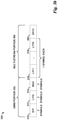
- FIG. 3a illustrates a third PHY frame 300, wherein PHY frame 300 is separated into multiple portions.
- PHY frame 300 includes an omni portion 305 that is non-beamformed and may be decoded by all stations, and a multi-stream portion 310 that may or may not be beamformed. If non-beamformed, multi-stream portion 310 may be decoded by all stations. If beamformed, multi-stream portion 310 may be difficult to decode by stations other than the destination station. It is noted that multi-stream portion 310 may include a data portion 315 of PHY frame 300.
- Omni portion 305 may include a STF 320, a LTF 322, and a first SIG field (SIGA) 324. Since omni portion 305 is non-beamformed, all stations may decode it, and LTF 322 may be used to help in the decoding of SIGA 324.
- Multi-stream portion 310 may include its own STF (AH-STF) 326, a plurality of N LTFs (AH-LTF1 - AH-LTFN) 328-330, and a second SIG field (SIGB) 332. Content of multi-stream portion 310 may be intended for exclusive use of the destination station. AH-LTF1 - AH-LTFN 328-330 may be used by the destination station to help in the decoding of SIGB 332 and/or data portion 315.
- AH-STF a plurality of N LTFs
- SIGB second SIG field
- FIG. 3b illustrates a fourth PHY frame 350, wherein PHY frame 350 is separated into multiple portions.
- PHY frame 350 includes an omni portion 355 that is non-beamformed and may be decoded by all stations, and a multi-stream portion 360 that may or may not be beamformed. It is noted that multi-stream portion 360 may include a data portion 365 of PHY frame 350.
- Omni portion 355 may include a STF 370, a LTF (LTF0) 372, and a SIG field (SIGA) 374. Since omni portion 355 is non-beamformed, all stations may decode it, and LTF 372 may be used to help in the decoding of SIGA 374.
- Multi-stream portion 360 may include a plurality of N LTFs (LTF1 - LTFN) 376-378. Content of multi-stream portion 360 may be intended for exclusive use of the destination station. LTF1 - LTFN 376-378 may be used by the destination station to help in the decoding of data portion 365.
- the destination station may need to know a beamform status of the multi-stream portion.
- a beamforming indicator may be used to indicate the beamform status of the multi-stream portion.
- a beamforming indicator located in a SIG field of an omni portion of a PHY frame may be used to indicate the beamform status of the multi-stream portion of the PHY frame.
- a bit or multiple bits of the SIG field may be used as the beamforming indicator.
- the beamforming indicator located in the SIG field may be set to a first value, e.g., a 1, to indicate that the multi-stream portion is beamformed.
- the beamforming indicator located in the SIG field may be set to a second value, e.g., a 0, to indicate that the multi-stream portion is non-beamformed.
- Figure 4a illustrates a PHY frame 400 wherein a beamforming indicator 410 of a SIG field 405 set to a first value indicates that a multi-stream portion of PHY frame 400 is beamformed.
- Figure 4b illustrates a PHY frame 450 wherein a beamforming indicator 460 of a SIG field 455 set to a second value indicates that a multi-stream portion of PHY frame 450 is non-beamformed.
- the beamforming indicator is set to a value of 1, a Q matrix is changed, while if the beamforming indicator is set to a value of 0, the Q matrix is unchanged. It is noted that the values may be reversed.
- signal intensity may be used to indicate the beamform status of the multi-stream portion of the PHY frame.
- Intensity detection may be used to detect signal intensity at different axes to detect the value of the beamforming indicator.
- either binary phase shift keying (BPSK) or quadrature binary phase shift keying (QBPSK) modulation may be employed in the SIG field or part of the SIG field to indicate the value of the beamforming indicator.
- BPSK binary phase shift keying
- QBPSK quadrature binary phase shift keying
- Figures 5a and 5b illustrate a constellation diagram of BPSK and QBPSK, respectively.
- Intensity detection may use intensity of signal(s) at different axes to detect the beamforming indicator.
- the I and/or Q axes are used as an illustrative examples.
- 2 as the signal intensity in the I and Q axes, respectively, where E is a complex number representing the signal intensity of the received signal, and E I and E Q are the real and imaginary parts of E , respectively.
- 2 is positive and
- 2 is zero and
- BPSK be used for either the SIG field or part of the SIG field to indicate a beamformed multi-stream portion
- QBPSK be used for either the SIG field or part of the SIG field to indicate a non-beamformed multi-stream portion. It is noted that the opposite designations may be used as well.
- the destination station After the destination station receives the SIG field, it can deduce the modulation type through a criterion, such as
- Table 1 illustrates a feature comparison chart, where HT-MM is an IEEE 802.11n mixed-mode preamble, Q is the beamforming steering matrix, D is the cyclic delay diversity (CDD), and P is the orthogonal mapping matrix. Table 1: Feature Comparison Chart. Q D P HT-MM NO YES NO Existing 802.11ah Preamble YES YES YES Example Embodiments YES YES YES
- Figure 6 illustrates a flow diagram of operations 600 in transmitting a PHY frame.
- Operations 600 may be indicative of operations occurring in a transmitting device, e.g., an access point, such as access point 105, as the access point transmits a PHY frame to a destination station.
- the PHY frame includes multiple portions, with an omni portion that is not beamformed and is decodable by all stations and a multi-stream portion that may or may not be beamformed intended for a destination station.
- Operations 600 may begin with the access point generating an omni portion of the PHY frame (block 605).
- the omni portion of the PHY frame may include a non-beamformed LTF and SIG field, with the non-beamformed LTF including channel estimation information used to decode the signal field.
- the non-beamformed LTF may be transmitted over a single space time stream.
- the access point may generate a multi-stream portion of the PHY frame (block 610).
- the multi-stream portion may include a multi-stream LTF and a data field and is intended for a destination station.
- the multi-stream LTF may contain station-specific decoding information for use by the destination station.
- the multi-stream portion may or may not be beamformed.
- the access point may apply a beamforming indicator to the SIG field of the omni portion of the PHY frame (block 615).
- applying the beamforming indicator may include setting one or more bits in the SIG field of the omni portion of the PHY frame to a value corresponding to a beamform status of the multi-stream portion of the PHY frame.
- the bit(s) may be set to a first value if the multi-stream portion is beamformed and a second value if the multi-stream portion is non-beamformed.
- applying the beamforming indicator may include applying a modulation technique commensurate with the beamform status of the multi-stream portion of the PHY frame to the SIG field or a portion of the SIG field.
- a BPSK modulation technique may be applied to the SIG field or a portion thereof if the multi-stream portion is beamformed and a QBPSK modulation technique may be applied to the SIG field or a portion thereof if the multi-stream portion is non-beamformed.
- the PHY frame may be transmitted (block 620).
- Figure 7 illustrates a flow diagram of operations 700 in receiving a PHY frame.
- Operations 700 may be indicative of operations occurring in a receiving device, e.g., a station, such as a destination station, as the station receives a PHY frame from an access point.
- the PHY frame includes multiple portions, with an omni portion that is not beamformed and is decodable by all stations and a multi-stream portion that may or may not be beamformed intended for the destination station.
- Operations 700 may begin with the station receiving an omni portion of the PHY frame (block 705). Since the omni portion is non-beamformed, the station may be able to decode the omni portion of the PHY frame (block 710). The station may use a LTF in the omni portion of the PHY frame to help it decode a SIG field. The station may perform a check to determine if it is the destination station of the omni portion (as well as a subsequent multi-stream portion) (block 715). If the station is not the destination station, the station may stop with the decoding of the omni portion of the PHY frame.
- the station may perform a check to determine if the multi-stream portion is beamformed, i.e., the station determines the beamform status of the multi-stream portion of the PHY frame (block 720). As discussed previously, the station may determine the beamform status of the multi-stream portion by examining a beamforming indicator.
- the beamforming indicator may be in the form of one or more bits in the SIG field of the omni portion.
- the beamforming indicator may also be in the form of a modulation technique used for the SIG field or a portion of the SIG field.
- the station may receive the non-beamformed multi-stream portion (block 725) and decode the non-beamformed multi-stream portion (block 730). If the multi-stream portion is beamformed, the station may receive the beamformed multi-stream portion (block 735) and decode the beamformed multi-stream portion (block 740).
- FIG 8 illustrates a diagram of a first communications device 800.
- Communications device 800 may be an implementation of an access point (or more generally, a transmitting device) of a communications system. Communications device 800 may be used to implement various ones of the embodiments discussed herein.
- a transmitter 805 is configured to send messages, and the like, and a receiver 810 is configured to receive messages, and the like.
- Transmitter 805 and receiver 810 may have a wireless interface, a wireline interface, or a combination thereof.
- a frame generating unit 820 is configured to generate a PHY frame, which includes an omni portion and a multi-stream portion.
- the omni portion includes a beamforming indicator of the beamform status of the multi-stream portion.
- a frame applying unit 822 is configured to apply the beamforming indicator to the omni portion.
- Frame applying unit 822 may set one or more bits in a SIG field in the omni portion to indicate the beamform status of the multi-stream portion or apply a modulation technique commensurate to the beamform status of the multi-stream portion to the SIG field or a portion thereof.
- a memory 830 is configured to store PHY frames, beamform status, beamforming indicators, and the like.
- the elements of communications device 800 may be implemented as specific hardware logic blocks. In an alternative, the elements of communications device 800 may be implemented as software executing in a processor, controller, application specific integrated circuit, or so on. In yet another alternative, the elements of communications device 800 may be implemented as a combination of software and/or hardware.
- transmitter 805 and receiver 810 may be implemented as a specific hardware block, while frame generating unit 820 and frame applying unit 822 may be software modules executing in a processor 815, such as a microprocessor, a digital signal processor, a custom circuit, or a custom compiled logic array of a field programmable logic array. Additionally, frame generating unit 820 and frame applying unit 822 may be software modules stored in memory 830.
- a processor 815 such as a microprocessor, a digital signal processor, a custom circuit, or a custom compiled logic array of a field programmable logic array.
- frame generating unit 820 and frame applying unit 822 may be software modules stored in memory 830.
- FIG. 9 illustrates a diagram of a second communications device 900.
- Communications device 900 may be an implementation of station (or more generally, a receiving device) of a communications system. Communications device 900 may be used to implement various ones of the embodiments discussed herein.
- a transmitter 905 is configured to send messages, and the like, and a receiver 910 is configured to receive messages, and the like.
- Transmitter 905 and receiver 910 may have a wireless interface, a wireline interface, or a combination thereof.
- a frame decoding unit 920 is configured to decode a frame or a portion of a frame.
- a recipient determining unit 922 is configured to determine if communications device 900 to determine if it is the destination station of the frame.
- a beamforming determining unit 924 is configured to determine if a frame is beamformed, i.e., determines the beamform status of the frame. Beamforming determining unit 924 determines the beamform status by examining a beamforming indicator, which may be in the form of one or more bits of a frame or a modulation technique used to modulate a field or a portion thereof.
- a memory 930 is configured to store frames, beamform status, beamforming indicators, and the like.
- the elements of communications device 900 may be implemented as specific hardware logic blocks. In an alternative, the elements of communications device 900 may be implemented as software executing in a processor, controller, application specific integrated circuit, or so on. In yet another alternative, the elements of communications device 900 may be implemented as a combination of software and/or hardware.
- transmitter 905 and receiver 910 may be implemented as a specific hardware block
- frame decoding unit 920, recipient determining unit 922, and beamforming determining unit 924 may be software modules executing in a processor 915, such as a microprocessor, a digital signal processor, a custom circuit, or a custom compiled logic array of a field programmable logic array.
- frame decoding unit 920, recipient determining unit 922, and beamforming determining unit 924 may be software modules stored in memory 930.
Applications Claiming Priority (7)
| Application Number | Priority Date | Filing Date | Title |
|---|---|---|---|
| US201161567777P | 2011-12-07 | 2011-12-07 | |
| US201161576614P | 2011-12-16 | 2011-12-16 | |
| US13/660,934 US9071489B2 (en) | 2011-12-07 | 2012-10-25 | System and method for preambles in a wireless communications network |
| EP12856086.9A EP2777236B1 (de) | 2011-12-07 | 2012-12-07 | System und verfahren für präambeln in einem drahtlosen kommunikationsnetz |
| EP17186456.4A EP3264705B1 (de) | 2011-12-07 | 2012-12-07 | System und verfahren für präambeln in einem drahtloskommunikationsnetzwerk |
| PCT/CN2012/086184 WO2013083083A1 (en) | 2011-12-07 | 2012-12-07 | System and method for preambles in a wireless communications network |
| EP18207216.5A EP3468127B1 (de) | 2011-12-07 | 2012-12-07 | System und verfahren für präambeln in einem drahtloskommunikationsnetzwerk |
Related Parent Applications (3)
| Application Number | Title | Priority Date | Filing Date |
|---|---|---|---|
| EP17186456.4A Division EP3264705B1 (de) | 2011-12-07 | 2012-12-07 | System und verfahren für präambeln in einem drahtloskommunikationsnetzwerk |
| EP18207216.5A Division EP3468127B1 (de) | 2011-12-07 | 2012-12-07 | System und verfahren für präambeln in einem drahtloskommunikationsnetzwerk |
| EP12856086.9A Division EP2777236B1 (de) | 2011-12-07 | 2012-12-07 | System und verfahren für präambeln in einem drahtlosen kommunikationsnetz |
Publications (1)
| Publication Number | Publication Date |
|---|---|
| EP3962012A1 true EP3962012A1 (de) | 2022-03-02 |
Family
ID=48571936
Family Applications (4)
| Application Number | Title | Priority Date | Filing Date |
|---|---|---|---|
| EP17186456.4A Active EP3264705B1 (de) | 2011-12-07 | 2012-12-07 | System und verfahren für präambeln in einem drahtloskommunikationsnetzwerk |
| EP18207216.5A Active EP3468127B1 (de) | 2011-12-07 | 2012-12-07 | System und verfahren für präambeln in einem drahtloskommunikationsnetzwerk |
| EP12856086.9A Active EP2777236B1 (de) | 2011-12-07 | 2012-12-07 | System und verfahren für präambeln in einem drahtlosen kommunikationsnetz |
| EP21186081.2A Pending EP3962012A1 (de) | 2011-12-07 | 2012-12-07 | System und verfahren für präambeln in einem drahtloskommunikationsnetzwerk |
Family Applications Before (3)
| Application Number | Title | Priority Date | Filing Date |
|---|---|---|---|
| EP17186456.4A Active EP3264705B1 (de) | 2011-12-07 | 2012-12-07 | System und verfahren für präambeln in einem drahtloskommunikationsnetzwerk |
| EP18207216.5A Active EP3468127B1 (de) | 2011-12-07 | 2012-12-07 | System und verfahren für präambeln in einem drahtloskommunikationsnetzwerk |
| EP12856086.9A Active EP2777236B1 (de) | 2011-12-07 | 2012-12-07 | System und verfahren für präambeln in einem drahtlosen kommunikationsnetz |
Country Status (5)
| Country | Link |
|---|---|
| US (4) | US9071489B2 (de) |
| EP (4) | EP3264705B1 (de) |
| CN (2) | CN103931153B (de) |
| ES (1) | ES2644583T3 (de) |
| WO (1) | WO2013083083A1 (de) |
Families Citing this family (15)
| Publication number | Priority date | Publication date | Assignee | Title |
|---|---|---|---|---|
| US9319896B2 (en) | 2012-05-03 | 2016-04-19 | MEDIATEK Singapore Ple. Ltd. | Beam-change indication for channel estimation improvement in wireless networks |
| US9485110B2 (en) * | 2013-07-15 | 2016-11-01 | Lg Electronics Inc. | Apparatus for alerting an emergency via broadcast signal transmission/reception and method for alerting an emergency via broadcast signal transmission/reception |
| US9991940B2 (en) * | 2013-09-10 | 2018-06-05 | Qualcomm Incorporated | Multi-user multiple-input multiple-output (MU-MIMO) feedback protocol |
| EP3160099B1 (de) | 2014-06-17 | 2018-12-05 | Huawei Technologies Co. Ltd. | Frameübertragungsverfahren und -vorrichtung für wlan |
| WO2016028124A1 (ko) * | 2014-08-21 | 2016-02-25 | 엘지전자(주) | 무선 통신 시스템에서 데이터 전송 방법 및 이를 위한 장치 |
| KR20160041007A (ko) * | 2014-10-06 | 2016-04-15 | 뉴라컴 인코포레이티드 | 고효율 무선랜에서 빔포밍된 전송 |
| EP3217588B1 (de) | 2014-11-05 | 2020-02-26 | LG Electronics Inc. | Verfahren und vorrichtung zur zuweisung einer ressourceneinheit basierend auf einem behälter in einem wlan |
| US10193604B2 (en) * | 2015-05-01 | 2019-01-29 | Futurewei Technologies, Inc. | Device, network, and method for receiving data transmission under scheduling decoding delay in mmWave communication |
| WO2017175500A1 (ja) * | 2016-04-07 | 2017-10-12 | ソニー株式会社 | 通信制御装置、端末装置、方法及びプログラム |
| CN109804569B (zh) | 2016-05-11 | 2021-12-07 | 索尼公司 | 无线系统中的分布式控制 |
| US10498418B2 (en) * | 2017-01-11 | 2019-12-03 | Qualcomm Incorporated | Fragmented beamforming for wireless devices |
| EP3834298A1 (de) * | 2018-08-09 | 2021-06-16 | Telefonaktiebolaget LM Ericsson (publ) | Senden und empfangen von signalen |
| JP7308623B2 (ja) * | 2019-02-28 | 2023-07-14 | キヤノン株式会社 | 情報処理装置並びにその制御方法、及び、プログラム |
| JP7280714B2 (ja) * | 2019-02-28 | 2023-05-24 | キヤノン株式会社 | 通信装置、通信方法、及び、プログラム |
| JP7273540B2 (ja) * | 2019-02-28 | 2023-05-15 | キヤノン株式会社 | 通信装置及びその通信方法、情報処理装置及びその制御方法、及び、プログラム |
Citations (4)
| Publication number | Priority date | Publication date | Assignee | Title |
|---|---|---|---|---|
| US20100260159A1 (en) * | 2009-04-13 | 2010-10-14 | Hongyuan Zhang | Physical layer frame format for wlan |
| WO2011031058A2 (en) * | 2009-09-09 | 2011-03-17 | Lg Electronics Inc. | Method and apparatus for transmitting control information in wlan system |
| US20110096796A1 (en) * | 2009-10-23 | 2011-04-28 | Hongyuan Zhang | Number of streams indication for wlan |
| WO2012177993A1 (en) * | 2011-06-24 | 2012-12-27 | Interdigital Patent Holdings, Inc. | Method and apparatus for receiving a preamble in a wireless communication system |
Family Cites Families (18)
| Publication number | Priority date | Publication date | Assignee | Title |
|---|---|---|---|---|
| US7395495B2 (en) | 2004-01-12 | 2008-07-01 | Intel Corporation | Method and apparatus for decoding forward error correction codes |
| US7324605B2 (en) * | 2004-01-12 | 2008-01-29 | Intel Corporation | High-throughput multicarrier communication systems and methods for exchanging channel state information |
| US8483200B2 (en) | 2005-04-07 | 2013-07-09 | Interdigital Technology Corporation | Method and apparatus for antenna mapping selection in MIMO-OFDM wireless networks |
| US7995665B2 (en) * | 2006-06-26 | 2011-08-09 | Ralink Technology (Singapore) Corporation Pte. Ltd. | Method and apparatus for reception in a multi-input-multi-output (MIMO) orthogonal frequency domain modulation (OFDM) wireless communication system |
| US8982889B2 (en) * | 2008-07-18 | 2015-03-17 | Marvell World Trade Ltd. | Preamble designs for sub-1GHz frequency bands |
| US8773994B2 (en) | 2009-04-10 | 2014-07-08 | Koninklijke Philips N.V. | Signaling method and apparatus to enable multiple antenna communications in wireless systems |
| US9503931B2 (en) * | 2009-08-12 | 2016-11-22 | Qualcomm Incorporated | Enhancements to the MU-MIMO VHT preamble to enable mode detection |
| EP3425841A1 (de) * | 2010-07-01 | 2019-01-09 | Marvell International Ltd. | Modulation eines signalfeldes bei einem frame-header in einem wlan |
| US9860037B2 (en) * | 2010-07-21 | 2018-01-02 | Qualcomm, Incorporated | Method and apparatus for ordering sub-fields of VHT-SIG-A and VIT-SIG-B fields |
| US8879472B2 (en) * | 2011-04-24 | 2014-11-04 | Broadcom Corporation | Long training field (LTF) for use within single user, multiple user, multiple access, and/or MIMO wireless communications |
| US20130177115A1 (en) * | 2011-07-05 | 2013-07-11 | Qualcomm Incorporated | Systems and methods for addressing doppler effect in wireless communications systems |
| WO2013025923A1 (en) * | 2011-08-18 | 2013-02-21 | Marvell World Trade Ltd. | Signal field design for wlan |
| US9100275B2 (en) * | 2011-09-06 | 2015-08-04 | Sameer Vermani | Signal unit including a field indicative of a zero-length payload |
| US9049155B2 (en) * | 2011-09-06 | 2015-06-02 | Qualcomm Incorporated | Dual interpretation of a length field of a signal unit |
| US8948284B2 (en) * | 2011-11-07 | 2015-02-03 | Lg Elecronics Inc. | Method and apparatus of transmitting PLCP header for sub 1 GHz communication |
| US8923432B2 (en) * | 2011-12-02 | 2014-12-30 | Qualcomm Incorporated | Systems and methods for communication over a plurality of frequencies and streams |
| CN103959670B (zh) * | 2011-12-02 | 2018-04-27 | 华为技术有限公司 | 用于在无线网络中进行流量标示和控制的系统和方法 |
| US9319896B2 (en) * | 2012-05-03 | 2016-04-19 | MEDIATEK Singapore Ple. Ltd. | Beam-change indication for channel estimation improvement in wireless networks |
-
2012
- 2012-10-25 US US13/660,934 patent/US9071489B2/en active Active
- 2012-12-07 EP EP17186456.4A patent/EP3264705B1/de active Active
- 2012-12-07 EP EP18207216.5A patent/EP3468127B1/de active Active
- 2012-12-07 CN CN201280055231.1A patent/CN103931153B/zh active Active
- 2012-12-07 EP EP12856086.9A patent/EP2777236B1/de active Active
- 2012-12-07 ES ES12856086.9T patent/ES2644583T3/es active Active
- 2012-12-07 WO PCT/CN2012/086184 patent/WO2013083083A1/en active Application Filing
- 2012-12-07 EP EP21186081.2A patent/EP3962012A1/de active Pending
- 2012-12-07 CN CN201710834141.7A patent/CN107612603B/zh active Active
-
2015
- 2015-06-04 US US14/730,728 patent/US9713031B2/en active Active
-
2017
- 2017-07-06 US US15/643,253 patent/US10285091B2/en active Active
-
2018
- 2018-11-20 US US16/196,880 patent/US10945157B2/en active Active
Patent Citations (4)
| Publication number | Priority date | Publication date | Assignee | Title |
|---|---|---|---|---|
| US20100260159A1 (en) * | 2009-04-13 | 2010-10-14 | Hongyuan Zhang | Physical layer frame format for wlan |
| WO2011031058A2 (en) * | 2009-09-09 | 2011-03-17 | Lg Electronics Inc. | Method and apparatus for transmitting control information in wlan system |
| US20110096796A1 (en) * | 2009-10-23 | 2011-04-28 | Hongyuan Zhang | Number of streams indication for wlan |
| WO2012177993A1 (en) * | 2011-06-24 | 2012-12-27 | Interdigital Patent Holdings, Inc. | Method and apparatus for receiving a preamble in a wireless communication system |
Also Published As
| Publication number | Publication date |
|---|---|
| US20150271704A1 (en) | 2015-09-24 |
| EP3468127A1 (de) | 2019-04-10 |
| WO2013083083A1 (en) | 2013-06-13 |
| CN103931153A (zh) | 2014-07-16 |
| EP2777236B1 (de) | 2017-09-06 |
| EP2777236A4 (de) | 2014-12-24 |
| US9713031B2 (en) | 2017-07-18 |
| US10945157B2 (en) | 2021-03-09 |
| CN103931153B (zh) | 2017-09-29 |
| US20190124549A1 (en) | 2019-04-25 |
| EP2777236A1 (de) | 2014-09-17 |
| US20170311203A1 (en) | 2017-10-26 |
| CN107612603A (zh) | 2018-01-19 |
| EP3264705A1 (de) | 2018-01-03 |
| EP3264705B1 (de) | 2020-09-02 |
| US20130148644A1 (en) | 2013-06-13 |
| US10285091B2 (en) | 2019-05-07 |
| CN107612603B (zh) | 2019-03-08 |
| EP3468127B1 (de) | 2021-08-18 |
| US9071489B2 (en) | 2015-06-30 |
| ES2644583T3 (es) | 2017-11-29 |
Similar Documents
| Publication | Publication Date | Title |
|---|---|---|
| US10945157B2 (en) | System and method for preambles in a wireless communications network | |
| US20200322005A1 (en) | Generating and processing multi-user data units for wlan | |
| US11025368B2 (en) | Physical layer frame format for WLAN | |
| JP6014948B2 (ja) | 長距離wlanのサウンディングパケット形式 | |
| US9843962B2 (en) | Dual-stream signal (SIG) field encoding with higher order modulation | |
| EP3402088B1 (de) | Verfahren und vorrichtung zur übertragung eines mimo-pakets in einem drahtlos-lan-system | |
| EP2509235A2 (de) | Verfahren und vorrichtung zur sendung eines rahmens in einem drahtlosen ran-system | |
| KR20120016234A (ko) | 무선 시스템들에서 다중 안테나 통신들을 인에이블하기 위한 시스널링 방법 및 장치 | |
| WO2016055020A2 (en) | System and method for space-time block coded communications | |
| US10306675B2 (en) | Collision detection and avoidance mechanism using distributed radio heads in a wireless network |
Legal Events
| Date | Code | Title | Description |
|---|---|---|---|
| PUAI | Public reference made under article 153(3) epc to a published international application that has entered the european phase |
Free format text: ORIGINAL CODE: 0009012 |
|
| STAA | Information on the status of an ep patent application or granted ep patent |
Free format text: STATUS: REQUEST FOR EXAMINATION WAS MADE |
|
| 17P | Request for examination filed |
Effective date: 20210716 |
|
| AC | Divisional application: reference to earlier application |
Ref document number: 2777236 Country of ref document: EP Kind code of ref document: P Ref document number: 3264705 Country of ref document: EP Kind code of ref document: P Ref document number: 3468127 Country of ref document: EP Kind code of ref document: P |
|
| AK | Designated contracting states |
Kind code of ref document: A1 Designated state(s): AL AT BE BG CH CY CZ DE DK EE ES FI FR GB GR HR HU IE IS IT LI LT LU LV MC MK MT NL NO PL PT RO RS SE SI SK SM TR |
|
| STAA | Information on the status of an ep patent application or granted ep patent |
Free format text: STATUS: EXAMINATION IS IN PROGRESS |
|
| 17Q | First examination report despatched |
Effective date: 20221223 |