EP3961985A1 - Alarme de service distribué à base d'intention - Google Patents
Alarme de service distribué à base d'intention Download PDFInfo
- Publication number
- EP3961985A1 EP3961985A1 EP20207488.6A EP20207488A EP3961985A1 EP 3961985 A1 EP3961985 A1 EP 3961985A1 EP 20207488 A EP20207488 A EP 20207488A EP 3961985 A1 EP3961985 A1 EP 3961985A1
- Authority
- EP
- European Patent Office
- Prior art keywords
- alarm
- devices
- rules
- execution engine
- rule execution
- Prior art date
- Legal status (The legal status is an assumption and is not a legal conclusion. Google has not performed a legal analysis and makes no representation as to the accuracy of the status listed.)
- Granted
Links
Images





Classifications
-
- H—ELECTRICITY
- H04—ELECTRIC COMMUNICATION TECHNIQUE
- H04L—TRANSMISSION OF DIGITAL INFORMATION, e.g. TELEGRAPHIC COMMUNICATION
- H04L41/00—Arrangements for maintenance, administration or management of data switching networks, e.g. of packet switching networks
- H04L41/06—Management of faults, events, alarms or notifications
- H04L41/0604—Management of faults, events, alarms or notifications using filtering, e.g. reduction of information by using priority, element types, position or time
-
- H—ELECTRICITY
- H04—ELECTRIC COMMUNICATION TECHNIQUE
- H04L—TRANSMISSION OF DIGITAL INFORMATION, e.g. TELEGRAPHIC COMMUNICATION
- H04L41/00—Arrangements for maintenance, administration or management of data switching networks, e.g. of packet switching networks
- H04L41/06—Management of faults, events, alarms or notifications
- H04L41/0631—Management of faults, events, alarms or notifications using root cause analysis; using analysis of correlation between notifications, alarms or events based on decision criteria, e.g. hierarchy, tree or time analysis
-
- G—PHYSICS
- G06—COMPUTING OR CALCULATING; COUNTING
- G06F—ELECTRIC DIGITAL DATA PROCESSING
- G06F9/00—Arrangements for program control, e.g. control units
- G06F9/06—Arrangements for program control, e.g. control units using stored programs, i.e. using an internal store of processing equipment to receive or retain programs
- G06F9/44—Arrangements for executing specific programs
- G06F9/455—Emulation; Interpretation; Software simulation, e.g. virtualisation or emulation of application or operating system execution engines
- G06F9/45533—Hypervisors; Virtual machine monitors
- G06F9/45558—Hypervisor-specific management and integration aspects
-
- H—ELECTRICITY
- H04—ELECTRIC COMMUNICATION TECHNIQUE
- H04L—TRANSMISSION OF DIGITAL INFORMATION, e.g. TELEGRAPHIC COMMUNICATION
- H04L41/00—Arrangements for maintenance, administration or management of data switching networks, e.g. of packet switching networks
- H04L41/06—Management of faults, events, alarms or notifications
-
- H—ELECTRICITY
- H04—ELECTRIC COMMUNICATION TECHNIQUE
- H04L—TRANSMISSION OF DIGITAL INFORMATION, e.g. TELEGRAPHIC COMMUNICATION
- H04L41/00—Arrangements for maintenance, administration or management of data switching networks, e.g. of packet switching networks
- H04L41/06—Management of faults, events, alarms or notifications
- H04L41/0681—Configuration of triggering conditions
-
- H—ELECTRICITY
- H04—ELECTRIC COMMUNICATION TECHNIQUE
- H04L—TRANSMISSION OF DIGITAL INFORMATION, e.g. TELEGRAPHIC COMMUNICATION
- H04L41/00—Arrangements for maintenance, administration or management of data switching networks, e.g. of packet switching networks
- H04L41/16—Arrangements for maintenance, administration or management of data switching networks, e.g. of packet switching networks using machine learning or artificial intelligence
-
- H—ELECTRICITY
- H04—ELECTRIC COMMUNICATION TECHNIQUE
- H04L—TRANSMISSION OF DIGITAL INFORMATION, e.g. TELEGRAPHIC COMMUNICATION
- H04L41/00—Arrangements for maintenance, administration or management of data switching networks, e.g. of packet switching networks
- H04L41/40—Arrangements for maintenance, administration or management of data switching networks, e.g. of packet switching networks using virtualisation of network functions or resources, e.g. SDN or NFV entities
-
- H—ELECTRICITY
- H04—ELECTRIC COMMUNICATION TECHNIQUE
- H04L—TRANSMISSION OF DIGITAL INFORMATION, e.g. TELEGRAPHIC COMMUNICATION
- H04L41/00—Arrangements for maintenance, administration or management of data switching networks, e.g. of packet switching networks
- H04L41/50—Network service management, e.g. ensuring proper service fulfilment according to agreements
- H04L41/5041—Network service management, e.g. ensuring proper service fulfilment according to agreements characterised by the time relationship between creation and deployment of a service
-
- H—ELECTRICITY
- H04—ELECTRIC COMMUNICATION TECHNIQUE
- H04L—TRANSMISSION OF DIGITAL INFORMATION, e.g. TELEGRAPHIC COMMUNICATION
- H04L43/00—Arrangements for monitoring or testing data switching networks
- H04L43/06—Generation of reports
- H04L43/065—Generation of reports related to network devices
-
- H—ELECTRICITY
- H04—ELECTRIC COMMUNICATION TECHNIQUE
- H04L—TRANSMISSION OF DIGITAL INFORMATION, e.g. TELEGRAPHIC COMMUNICATION
- H04L43/00—Arrangements for monitoring or testing data switching networks
- H04L43/20—Arrangements for monitoring or testing data switching networks the monitoring system or the monitored elements being virtualised, abstracted or software-defined entities, e.g. SDN or NFV
-
- G—PHYSICS
- G06—COMPUTING OR CALCULATING; COUNTING
- G06F—ELECTRIC DIGITAL DATA PROCESSING
- G06F9/00—Arrangements for program control, e.g. control units
- G06F9/06—Arrangements for program control, e.g. control units using stored programs, i.e. using an internal store of processing equipment to receive or retain programs
- G06F9/44—Arrangements for executing specific programs
- G06F9/455—Emulation; Interpretation; Software simulation, e.g. virtualisation or emulation of application or operating system execution engines
- G06F9/45533—Hypervisors; Virtual machine monitors
- G06F9/45558—Hypervisor-specific management and integration aspects
- G06F2009/45595—Network integration; Enabling network access in virtual machine instances
Definitions
- This disclosure relates to computer networks and, more specifically, to anomaly detection in computer networks.
- Virtualized data centers are becoming a core foundation of the modern information technology (IT) infrastructure.
- modern data centers have extensively utilized virtualized environments in which virtual hosts, such virtual machines or containers, are deployed and executed on an underlying compute platform of physical computing devices.
- Virtualization within a large-scale data center can provide several advantages, including efficient use of computing resources and simplification of network configuration.
- enterprise IT staff often prefer virtualized compute clusters in data centers for their management advantages in addition to the efficiency and increased return on investment (ROI) that virtualization provides.
- ROI return on investment
- Supporting virtualization in large scale data center can require numerous network devices and host devices that can be coupled together in a data center network. Additionally, network devices in a data center may be allocated to different tenants. Configuring devices to generate data used for anomaly detection and alarm generation can be difficult given the large number of network devices, different types of network devices, and different tenants that may be present in a data center.
- This disclosure describes techniques for providing a sharable alarm service to perform anomaly detection and alarm generation for cloud infrastructure monitoring that can be used by multiple applications and tenants at a cloud scale.
- An administrator can express an alarm rule as an "intent” that defines a rule in a high level “natural language.”
- An alarm rule compiler can receive the intent and translate the high level intent into one or more lower level rules that can be programmatically processed by multiple alarm rule execution engines.
- devices in a network system can be associated with alarm rule execution engines in a distributed manner. For example, devices in a network can be associated with different instances of an alarm rule execution engine, thus distributing the resource usage for obtaining telemetry data and processing alarms with respect to the devices in a network across multiple alarm rule execution engines.
- the techniques described herein may provide one or more technical advantages.
- the techniques may facilitate the use of alarm rule execution engines that may be implemented as microservices, and that may be fault tolerant and scalable.
- the alarm service can be easily scaled to meet variations in the number of devices in use by a network system.
- the alarm service is easy to use by network administrators, because the administrator can express an intent in a high level natural language, and the alarm service can translate the administrator's intent into lower level rules that define the devices and metrics that need to be accessed in order to implement the administrator's intent.
- a method includes allocating, by one or more processors, a plurality of devices among a plurality of instances of an alarm rule execution engine; receiving, by the one or more processors, data representing an alarm intent; translating, by the one or more processors, the data representing the alarm intent into one or more rules, the one or more rules specifying alarm criteria for respective alarms for the one or more rules; determining, by the one or more processors, a set of devices of the plurality of devices that are specified by the one or more rules; assigning, by the one or more processors, the one or more rules to respective instances of the plurality of instances of the alarm rule execution engine to which the set of devices has been allocated, wherein each respective instance of the alarm rule execution engine is configured to apply the one or more rules to the devices of the set of devices allocated to the respective instance of the alarm rule execution engine; registering the set of devices specified by the one or more rules with a telemetry service, wherein the set of devices provide telemetry data in response to the registering; subscribing, by
- an alarm service system includes an alarm controller executable by one or more processors and configured to allocate a plurality of devices among a plurality of instances of an alarm rule execution engine; an alarm intent compiler executable by the one or more processors and configured to: receive data representing an alarm intent, translate the data representing the alarm intent into one or more rules, the one or more rules specifying alarm criteria for respective alarms for the one or more rules, and determine a set of devices of the plurality of devices that are specified by the one or more rules; and an alarm rule programmer executable by the one or more processors and configured to assign the one or more rules to respective instances of the plurality of instances of the alarm rule execution engine to which the set of devices has been allocated, wherein each respective instance of the alarm rule execution engine is configured to apply the one or more rules to the devices of the set of devices allocated to the respective instance of the alarm rule execution engine; wherein the alarm rule controller is further configured to register the set of devices specified by the one or more rules with a telemetry service, wherein the set of devices provide telemetry data in
- a computer-readable storage medium includes instructions that, when executed, cause processing circuitry of a computing system to: allocate a plurality of devices among a plurality of instances of an alarm rule execution engine; receive data representing an alarm intent; translate the data representing the alarm intent into one or more rules, the one or more rules specifying alarm criteria for respective alarms for the one or more rules; determine a set of devices of the plurality of devices that are specified by the one or more rules; assign the one or more rules to respective instances of the plurality of instances of the alarm rule execution engine to which the set of devices has been allocated, wherein each respective instance of the alarm rule execution engine is configured to apply the one or more rules to the devices of the set of devices allocated to the respective instance of the alarm rule execution engine; register the set of devices specified by the one or more rules with a telemetry service, wherein the set of devices provide telemetry data in response to the registration; subscribe, by the respective instances of the plurality of instances of the alarm rule execution engine, to the telemetry data to obtain the telemetry data;
- Data centers that use virtualized environments in which virtual hosts, virtual machines, or containers are deployed and executed on an underlying compute platform of physical computing devices provide efficiency, cost, and organizational advantages.
- a typical data center employs numerous network devices and host devices that are used to support the virtualized environment and enable communication between entities both within the data center and external to the data center.
- Monitoring the numerous devices in a data center for anomalies may be useful in efficiently managing a data center fabric. Further, monitoring the devices in a data center for anomalies may facilitate early detection and resolution of problems, thus increasing user satisfaction with the data center. Telemetry data from networking devices and host devices may facilitate detection of anomalies.
- collecting sufficient data from network devices to facilitate anomaly detection can be a challenge, particularly given the number of network devices and host devices in a network and the variety of different network devices and host devices in the network. It can be difficult for a network administrator to master all of the different commands or application program interfaces (APIs) that may be necessary to collect telemetry data from the devices in a network.
- APIs application program interfaces
- Techniques are described herein to enable a network administrator to indicate the administrator's intent with respect to obtaining telemetry data for devices in a network.
- the administrator's intent can be translated into one or more lower level rules that conform to different protocols and metrics that can be obtained from network devices. Further, the techniques described herein can facilitate an alarm service that can be readily scaled up as the network grows.
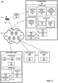
- FIG. 1 is a conceptual diagram illustrating an example network that includes an anomaly detection service 140 in a network, for example, a network within a data center, in accordance with one or more aspects of the present disclosure.
- FIG. 1 illustrates one example implementation of a network system 100 and a data center 101 that hosts one or more computing networks, computing domains or projects, and/or cloud-based computing networks.
- Network system 100 may include one or more cloud-based computing clusters that may be co-located in a common overall computing environment, such as a single data center, or distributed across environments, such as across different data centers.
- Cloud-based computing clusters may, for example, be different cloud environments, such as various combinations of OpenStack cloud environments, Kubernetes cloud environments, collections of bare metal servers, Contrail or Tungsten clusters, or other computing clusters, domains, networks and the like.
- Other implementations of network system 100 and data center 101 may be appropriate in other instances. Such implementations may include a subset of the components included in the example of FIG. 1 and/or may include additional components not shown in FIG. 1 .
- data center 101 provides an operating environment for applications and services for customers 104 coupled to data center 101 by service provider network 106.
- functions and operations described in connection with network system 100 of FIG. 1 may be illustrated as being distributed across multiple devices in FIG. 1 , in other examples, the features and techniques attributed to one or more devices in FIG. 1 may be performed internally, by local components of one or more of such devices. Similarly, one or more of such devices may include certain components and perform various techniques that may otherwise be attributed in the description herein to one or more other devices. Further, certain operations, techniques, features, and/or functions may be described in connection with FIG. 1 or otherwise as performed by specific components, devices, and/or modules.
- Data center 101 hosts infrastructure equipment, such as networking and storage systems, redundant power supplies, and environmental controls.
- Service provider network 106 may be coupled to one or more networks administered by other providers, and may thus form part of a large-scale public network infrastructure, e.g., the Internet.
- data center 101 may represent one of many geographically distributed network data centers. As illustrated in the example of FIG. 1 , data center 101 is a facility that provides network services for customers 104. Customers 104 may be collective entities such as enterprises and governments or individuals. For example, a network data center may host web services for several enterprises and end users. Other example services may include data storage, virtual private networks, traffic engineering, file service, data mining, scientific- or super-computing, and so on.
- data center 101 includes a set of storage systems, application servers, compute nodes, or other devices, including device 110A through device 110N (collectively "devices 110," representing any number of network devices).
- Devices 110 may be interconnected via high-speed switch fabric 121 provided by one or more tiers of physical network switches and routers. In some examples, devices 110 may be included within fabric 121, but are shown separately for ease of illustration.
- Devices 110 may be any of a number of different types of network devices (core switches, spine network devices, leaf network devices, edge network devices, or other network devices), but in some examples, one or more devices 110 may serve as physical compute nodes and/or storage nodes of the data center. For example, one or more of devices 110 may provide an operating environment for execution of one or more customer-specific applications or services. Alternatively, or in addition, one or more of devices 110 may provide an operating environment for one or more virtual machines or other virtualized instances, such as containers. In some examples, one or more of devices 110 may be alternatively referred to as a host computing device or, more simply, as a host. A device 110 may thereby execute one or more virtualized instances, such as virtual machines, containers, or other virtual execution environment for running one or more applications or services, such as virtualized network functions (VNFs).
- VNFs virtualized network functions
- each of devices 110 may be any type of device that may operate on a network and which may generate data (e.g. connectivity data, flow data, sFlow data, resource utilization data) accessible through telemetry or otherwise, which may include any type of computing device, sensor, camera, node, surveillance device, or other device. Further, some or all of devices 110 may represent a component of another device, where such a component may generate data collectible through telemetry or otherwise. For example, some or all of devices 110 may represent physical or virtual network devices, such as switches, routers, hubs, gateways, security devices such as firewalls, intrusion detection, and/or intrusion prevention devices.
- switch fabric 121 may include top-of-rack (TOR) switches coupled to a distribution layer of chassis switches, and data center 101 may include one or more non-edge switches, routers, hubs, gateways, security devices such as firewalls, intrusion detection, and/or intrusion prevention devices, servers, computer terminals, laptops, printers, databases, wireless mobile devices such as cellular phones or personal digital assistants, wireless access points, bridges, cable modems, application accelerators, or other network devices.
- Switch fabric 121 may perform layer 3 routing to route network traffic between data center 101 and customers 104 by service provider network 106.
- Gateway 108 acts to send and receive packets between switch fabric 121 and service provider network 106.
- orchestration engine 130 manages functions of data center 101 such as compute, storage, networking, and application resources. Orchestration engine 130 may implement a security policy across a group of VMs or to the boundary of a tenant's network. Orchestration engine 130 may deploy a network service (e.g. a load balancer) in a tenant's virtual network.
- a network service e.g. a load balancer
- SDN controller 132 provides a logically and in some cases physically centralized controller for facilitating operation of one or more virtual networks within data center 101 in accordance with one or more examples of this disclosure.
- SDN controller 132 operates in response to configuration input received from orchestration engine 130 via northbound application programming interface (API) 131, which in turn may operate in response to configuration input received from an administrator 128 interacting with and/or operating user interface device 129.
- API application programming interface
- SDN controller 132 may create a virtual network for a tenant within data center 101 or across data centers.
- SDN controller 132 may attach virtual machines (VMs) to a tenant's virtual network.
- SDN controller 132 may connect a tenant's virtual network to an external network, e.g. the Internet or a VPN.
- VMs virtual machines
- SDN controller 132 manages the network and networking services such load balancing, security, and may allocate resources from devices 110 that serve as host devices to various applications via southbound API 133. That is, southbound API 133 represents a set of communication protocols utilized by SDN controller 132 to make the actual state of the network equal to the desired state as specified by orchestration engine 130.
- SDN controller 132 may implement high-level requests from orchestration engine 130 by configuring physical switches, e.g. top-of-rack (TOR) switches, chassis switches, and switch fabric 121; physical routers; physical service nodes such as firewalls and load balancers; and virtual services such as virtual firewalls in a VM.
- SDN controller 132 maintains routing, networking, and configuration information within a state database. Different cloud computing clusters may have separate instances of SDN controller 132.
- Alarm service 140 can configure devices 110 (and/or other devices) to collect and provide telemetry data related to the operations of devices 110. Such data can include process usage data, memory usage data, network usage data, error counts etc. Alarm service 140 can be configured with rules to determine if an alarm is to be generated based on the telemetry data. Applications, processes, threads etc. can subscribe to the alarm in order to be notified when an alarm is triggered based on current conditions on a device or devices on a network.
- User interface device 129 may be implemented as any suitable device for presenting output and/or accepting user input.
- user interface device 129 may include a display.
- User interface device 129 may be a computing system, such as a mobile or non-mobile computing device operated by a user and/or by administrator 128.
- User interface device 129 may, for example, represent a workstation, a laptop or notebook computer, a desktop computer, a tablet computer, or any other computing device that may be operated by a user and/or present a user interface in accordance with one or more aspects of the present disclosure.
- user interface device 129 may be physically separate from and/or in a different location than controller 132. In such examples, user interface device 129 may communicate with controller 132 over a network or other means of communication.
- user interface device 129 may be a local peripheral of controller 132, or may be integrated into controller 132.
- user interface device 129 may communicate with alarm service 140 or a component thereof to configure the alarm service 140 to configure alarms using high-level statements of intent and to receive alerts, logs, or other data from devices 110 and other components of data center 101.
- alarm service 140 can provide a sharable alarm service to perform anomaly detection and alarm generation for cloud infrastructure monitoring that can be used by multiple applications and tenants at a cloud scale.
- An administrator 128 can utilize UI device 129 to input data expressing an alarm rule as an "intent" that defines a rule in a high level "natural language"
- Alarm service 140 can receive the data representing the intent and translate the high level intent into one or more lower level rules that can be programmatically processed by multiple alarm rule execution engines of alarm service 140.
- devices 110 in a network system can be associated with the alarm rule execution engines in a distributed manner.
- devices 110 in a network can be associated with different instances of an alarm rule execution engine, thus distributing the resource usage for obtaining telemetry data and processing alarms with respect to the devices in a network across multiple alarm rule execution engines.
- FIG. 2 is a block diagram illustrating an example system including an alarm service in a network and/or within a data center, in accordance with one or more aspects of the present disclosure.
- Network system 200 of FIG. 2 may be described as an example or alternative implementation of network system 100 of FIG. 1 .
- One or more aspects of FIG. 2 may be described herein within the context of FIG. 1 .
- a data center such as that illustrated in FIG. 1 and FIG. 2 may be operated by any entity
- some data centers are operated by a service provider, where the business model of such a service provider may involve providing computing capacity to customers or clients.
- data centers usually contain a huge number of compute nodes, or host devices.
- those hosts In order to operate efficiently, those hosts have to be connected to each other and to the external world, and that ability is provided through physical network devices, which may be interconnected in a leaf-spine topology.
- Each host device in such a data center may have several virtual machines running on it, which may be referred to as workloads.
- Clients of the data center usually have access to these workloads, and can install applications and perform other operations using such workloads.
- Workloads that run on different host devices but are accessible by one particular client are organized into a virtual network.
- Each client usually has at least one virtual network. Those virtual networks are also called overlay networks.
- a client of the data center may experience network issues such as increased latency, packet loss, low network throughput, or slow workload processing. Troubleshooting such issues may be complicated by the deployment of workloads in a large multitenant data center.
- network 205 connects alarm service 140, host device 210A, and host devices 210B - 210N.
- Alarm service 140 may correspond to an example or alternative implementation of alarm service 140 illustrated in FIG. 1 .
- Host devices 210A, 210B, through 210N may be collectively referenced as "host devices 210," representing any number of host devices 210.
- Each of host devices 210 may be an example of devices 110 of FIG. 1 , but in the example of FIG. 2 , each of host devices 210 is implemented as a server or host device that operates as a physical or virtualized compute node or a storage node of a virtualized data center, as opposed to a network device.
- one or more of host devices 210 e.g., host device 210A of FIG. 2
- FIG. 1 the example of FIG. 2 illustrates a network system that may include a mix of virtualized server devices and bare metal server devices.
- user interface device 129 Also connected to network 205 is user interface device 129, which may be operated by administrator 128, as in FIG. 1 .
- user interface device 129 may present, at a display device associated with user interface device 129, one or more user interfaces.
- Network 205 may correspond to any of switch fabric 121 and/or service provider network 106 of FIG. 1 , or alternatively, may correspond to a combination of switch fabric 121, service provider network 106, and/or another network. Although not shown in FIG. 2 , network 205 may also include some of the components of FIG. 1 , including gateway 108, SDN controller 132, and orchestration engine 130.
- network 205 Illustrated within network 205 are spine devices 202A and 202B (collectively “spine devices 202" and representing any number of spine devices 202), as well as leaf device 203A, 203B, and leaf device 203C (collectively “leaf devices 203" and also representing any number of leaf devices 203).
- spine devices 202A and 202B collectively “spine devices 202” and representing any number of spine devices 202
- leaf device 203A, 203B, and leaf device 203C collectively “leaf devices 203” and also representing any number of leaf devices 203.
- network 205 is illustrated with spine devices 202 and leaf devices 203, other types of network devices may be included in network 205, including core switches, edge network devices, top-of-rack devices, and other network devices.
- network 205 may be the internet, or may include or represent any public or private communications network or other network.
- network 205 may be a cellular, Wi-Fi ® , ZigBee, Bluetooth, Near-Field Communication (NFC), satellite, enterprise, service provider, and/or other type of network enabling transfer of transmitting data between computing systems, servers, and computing devices.
- client devices, server devices, or other devices may transmit and receive data, commands, control signals, and/or other information across network 205 using any suitable communication techniques.
- Network 205 may include one or more network hubs, network switches, network routers, satellite dishes, or any other network equipment.
- Such devices or components may be operatively inter-coupled, thereby providing for the exchange of information between computers, devices, or other components (e.g., between one or more client devices or systems and one or more server devices or systems).
- Each of the devices or systems illustrated in FIG. 2 may be operatively coupled to network 205 using one or more network links.
- the links coupling such devices or systems to network 205 may be Ethernet, Asynchronous Transfer Mode (ATM) or other types of network connections, and such connections may be wireless and/or wired connections.
- ATM Asynchronous Transfer Mode
- One or more of the devices or systems illustrated in FIG. 2 or otherwise on network 205 may be in a remote location relative to one or more other illustrated devices or systems.
- Each of host devices 210 represents a physical computing device or compute node or storage node that provides an execution environment for virtual hosts, virtual machines, containers, and/or other real or virtualized computing resources.
- each of host devices 210 may be a component of a cloud computing system, server farm, and/or server cluster (or portion thereof) that provides services to client devices and other devices or systems.
- host devices 210 are described herein with respect to host device 210A.
- Other host devices 210 e.g., host device 210B through 210N
- Descriptions herein with respect to host device 210A may therefore correspondingly apply to one or more other host devices 210 (e.g., host device 210B through host device 210N).
- host device 210A includes underlying physical compute hardware that includes one or more processors 213, one or more communication units 215, one or more input devices 216, one or more output devices 217, and one or more storage devices 220.
- storage devices 220 may include kernel module 222 and virtual router module 224.
- Storage devices 220 may also include virtual machines 228A through 228N (collectively "virtual machines 228" and representing any number of virtual machines 228), when present, may execute on top of a hypervisor (not shown) or may be controlled by a hypervisor.
- One or more of the devices, modules, storage areas, or other components of host device 210A may be interconnected to enable inter-component communications (physically, communicatively, and/or operatively).
- such connectivity may be provided by through communication channels (e.g., communication channels 212), a system bus, a network connection, an inter-process communication data structure, or any other method for communicating data.
- Processor 213 may implement functionality and/or execute instructions associated with host device 210A.
- Communication unit 215 may communicate with other devices or systems on behalf of host device 210A.
- One or more input devices 216 and output devices 217 may represent any other input and/or output devices associated with host device 210A.
- Storage devices 220 may store information for processing during operation of host device 210A. Each of such components may be implemented in a manner similar to those described herein in connection with alarm service 140 or otherwise.
- Virtual router module 224 may execute multiple routing instances for corresponding virtual networks within data center 101 ( FIG. 1 ) and may route packets to appropriate virtual machines executing within the operating environment provided by devices 110. Virtual router module 224 may also be responsible for collecting overlay flow data, such as Contrail Flow data when used in an infrastructure in which the Contrail SDN is employed.
- Virtual machine 228A through virtual machine 228N may represent example instances of virtual machines 228.
- Host device 210A may partition the virtual and/or physical address space provided by storage device 220 into user space for running user processes.
- Host device 210A may also partition virtual and/or physical address space provided by storage device 220 into kernel space, which is protected and may be inaccessible by user processes.
- Each of virtual machines 228 may represent a tenant virtual machine running customer applications such as Web servers, database servers, enterprise applications, or hosting virtualized services used to create service chains.
- any one or more of host devices 210 or another computing device hosts customer applications directly, i.e., not as virtual machines (e.g., one or more of host devices 210B through 210N, such as host device 210B and host device 210N).
- virtual machines e.g., one or more of host devices 210B through 210N, such as host device 210B and host device 210N.
- alarm service 140 may include one or more processors 243, one or more communication units 245, one or more input devices 246, one or more output devices 247 and one or more storage devices 250.
- Storage devices 250 may include alarm rule intent programming interface 221, alarm rule intent compiler 218, alarm notification subscription service 208, alarm rule execution engines 214 and data store 259.
- One or more of the devices, modules, storage areas, or other components of alarm service 140 may be interconnected to enable inter-component communications (physically, communicatively, and/or operatively).
- such connectivity may be provided by through communication channels (e.g., communication channels 242), a system bus, a network connection, an inter-process communication data structure, or any other method for communicating data.
- One or more processors 243 of alarm service 140 may implement functionality and/or execute instructions associated with alarm service 140 or associated with one or more modules illustrated herein and/or described herein.
- One or more processors 243 may be, may be part of, and/or may include processing circuitry that performs operations in accordance with one or more aspects of the present disclosure. Examples of processors 243 include microprocessors, application processors, display controllers, auxiliary processors, one or more sensor hubs, and any other hardware configured to function as a processor, a processing unit, or a processing device.
- One or more communication units 245 of alarm service 140 may communicate with devices external to alarm service 140 by transmitting and/or receiving data, and may operate, in some respects, as both an input device and an output device.
- communication unit 245 may communicate with other devices over a network.
- communication units 245 may send and/or receive radio signals on a radio network such as a cellular radio network.
- Examples of communication units 245 include a network interface card (e.g. such as an Ethernet card), an optical transceiver, a radio frequency transceiver, a GPS receiver, or any other type of device that can send and/or receive information.
- communication units 245 may include devices capable of communicating over Bluetooth ® , GPS, NFC, ZigBee, and cellular networks (e.g., 3G, 4G, 5G), and Wi-Fi ® radios found in mobile devices as well as Universal Serial Bus (USB) controllers and the like. Such communications may adhere to, implement, or abide by appropriate protocols, including Transmission Control Protocol/Internet Protocol (TCP/IP), Ethernet, Bluetooth, NFC, or other technologies or protocols.
- TCP/IP Transmission Control Protocol/Internet Protocol
- Ethernet e.g., Ethernet, Bluetooth, NFC, or other technologies or protocols.
- One or more input devices 246 may represent any input devices of alarm service 140 not otherwise separately described herein.
- One or more input devices 246 may generate, receive, and/or process input from any type of device capable of detecting input from a human or machine.
- one or more input devices 246 may generate, receive, and/or process input in the form of electrical, physical, audio, image, and/or visual input (e.g., peripheral device, keyboard, microphone, camera).
- One or more output devices 247 may represent any output devices of alarm service 140 not otherwise separately described herein.
- One or more output devices 247 may generate, receive, and/or process input from any type of device capable of detecting input from a human or machine.
- one or more output devices 247 may generate, receive, and/or process output in the form of electrical and/or physical output (e.g., peripheral device, actuator).
- One or more storage devices 250 within alarm service 140 may store information for processing during operation of alarm service 140.
- Storage devices 250 may store program instructions and/or data associated with one or more of the modules described in accordance with one or more aspects of this disclosure.
- One or more processors 243 and one or more storage devices 250 may provide an operating environment or platform for such modules, which may be implemented as software, but may in some examples include any combination of hardware, firmware, and software.
- One or more processors 243 may execute instructions and one or more storage devices 250 may store instructions and/or data of one or more modules. The combination of processors 243 and storage devices 250 may retrieve, store, and/or execute the instructions and/or data of one or more applications, modules, or software.
- Processors 243 and/or storage devices 250 may also be operably coupled to one or more other software and/or hardware components, including, but not limited to, one or more of the components of alarm service 140 and/or one or more devices or systems illustrated as being connected to alarm service 140.
- one or more storage devices 250 are implemented through temporary memory, which may mean that a primary purpose of the one or more storage devices is not long-term storage.
- Storage devices 250 of alarm service 140 may be configured for short-term storage of information as volatile memory and therefore not retain stored contents if deactivated. Examples of volatile memories include random access memories (RAM), dynamic random access memories (DRAM), static random access memories (SRAM), and other forms of volatile memories known in the art.
- Storage devices 250 also include one or more computer-readable storage media. Storage devices 250 may be configured to store larger amounts of information than volatile memory. Storage devices 250 may further be configured for long-term storage of information as non-volatile memory space and retain information after activate/off cycles. Examples of non-volatile memories include magnetic hard disks, optical discs, Flash memories, or forms of electrically programmable memories (EPROM) or electrically erasable and programmable (EEPROM) memories.
- EPROM electrically programmable memories
- EEPROM electrically erasable and programmable
- Alarm rule intent compiler 218 receives an alarm intent 230 that expresses, at a high level, an intent for alarm generation and translates the alarm intent into one or more lower level alarm rules that implement the alarm intent 230.
- the alarm intent 230 may be in a natural language.
- an alarm intent 230 may be "Notify if CPU and Network Usage deviates from normal behavior in a cluster.”
- alarm rule intent compiler 218 may automatically generate, from alarm intent 130, three alarm rules:
- Alarm rule intent compiler 218 may also perform optimizations in alarm rule generation. For example, alarm rule intent compiler 218 may map new alarm intents to existing alarm intents if an alarm intent exists that can be represented as a function of existing alarm intents. Alarm rule intent compiler 218 may optimize the alarm rules by combining rules. As an example, assume that two alarm intents 230, "Intent1" and “Intent2,” have been previously received and processed by alarm rule intent compiler 218 to produce alarm rules "AlarmRuleSet1" and "AlarmRuleSet2" respectively. Next, assume a new alarm intent 230, "Intent3" is received after Intent1 and Intent2 have been processed. Alarm rule intent compiler 218 may detect that Intent3 is a combination of Intent1 and Intent2.
- alarm rule intent compiler 230 may generate an alarm rule that is a combination of the rules for Intent1 and Intent2, thereby avoiding generation of a totally new set of alarm rules for Intent3.
- Alarm rules generated by alarm rule intent compiler 218 may be stored as alarm rules 232 in data store 259.
- Alarm rule intent programmer 221 receives alarm rules and determines one or more alarm rule execution engines 214 that are to process the alarm rules.
- Alarm rule intent instance 221 may program mutually exclusive subsets of alarm rules to alarm rule execution engines 214.
- Each alarm rule intent programmer 221 may independently determine the resources that are utilized by the rule and/or need to be created for the rule and to which alarm rule execution engine 214 that a rule is to be posted for processing.
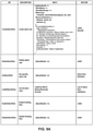
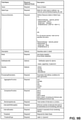
- alarm rule intent programmer may use an API shown in FIG. 9A to program rules to alarm rules execution engines 214. Parameters used by various functions of the API are shown in FIG. 9B .
- Alarm rule execution engines 214 receive telemetry data from network devices 202 and 203, and from host devices 210. Alarm rule execution engines 214 apply the rules for which they have been programmed to the telemetry data and, if the rule is satisfied, generate the corresponding alarm for the rule. In some aspects, alarm rule execution engines 214 receive a stream of telemetry data from a network device 202, 203 or host device 210 and analysis on a sliding window of telemetry data in the telemetry window data stream.
- an alarm rule definition may be "if 'average' of 'metric_1' is 'above' 'threshold' over '1 minute' monitoring interval for 3 out of the last 5 monitoring intervals then raise alarm.” After sliding window analysis, if the conditions for the alarm rule are met, and alarm can be generated.
- Alarm notification subscription service 208 provides an interface for applications (e.g., any of applications 226A, 226B, ... , 226N etc.) to notify the alarm service 140 that the application wishes to receive notifications of alarms.
- the application can specify the alarms or type of alarms for which the application is interested in receiving notifications.
- Data store 259 may represent any suitable data structure or storage medium for storing information related to configuring and processing alarms and telemetry, including storage of rules 232 and alarm history 234.
- Data store 259 may be responsible for storing data in an indexed format, enabling fast data retrieval and execution of queries.
- the information stored in data store 259 may be searchable and/or categorized such that one or more modules within alarm service 140 may provide an input requesting information from data store 259, and in response to the input, receive information stored within data store 259.
- Data store 259 may be implemented through multiple hardware devices, and may achieve fault tolerance and high availability by sharding and replicating data.
- FIG. 3 is a block diagram illustrating further details of an alarm service, in accordance with one or more aspects of the present disclosure.
- alarm service 140 includes components described above with respect to FIG. 2 , that is, alarm rule intent compiler 218, alarm rule programmer 221, alarm rule execution engines 214, and alarm notification subscription service 208.
- alarm service 140 includes inventory service 316, alarm controller 330, alarm rule execution service 332, publication platform 314, alarm data adapter 310, and alarm notifier 306.
- Inventory service 316 can provide information about network resources that are available for a network 205. Such information can include the network devices, host devices, services, etc. that are coupled to the network, and the status of such resources.
- Alarm controller 330 can register devices with a network telemetry service to initiate collection of telemetry data for the devices and metrics that are specified in alarm rules generated by alarm rule intent compiler 218.
- alarm controller 330 can select an appropriate protocol to use to collect the telemetry data from a device.
- alarm controller 330 may select a protocol based on network or data management protocols supported by the device using information obtained from the device or from inventory service 316.
- An application such as an Element Management Service (EMS) application 302 may provide an alarm intent 230 to alarm rule intent compiler 218.
- EMS Element Management Service
- a network administrator may provide an alarm intent 230 via EMS application 302.
- alarm controller 330 can provision telemetry collectors that can collect the desired telemetry data from the devices specified in the rules generated from the alarm intent.
- alarm controller can issue a request to telemetry controller 328 to provision telemetry collectors.
- a set of sensors and protocols can be determined which can be used by the telemetry collector to collect desire telemetry data from devices.
- alarm controller 330 can query a telemetry service 327 about its capabilities for telemetry collection. Once capabilities of telemetry collectors are determined, then alarm service 140 can request the appropriate telemetry protocol and sensor(s).
- SNMP Simple Network Management Protocol
- gRPC Google Remote Procedure Calls
- JTI Junos Telemetry Interface
- telemetry service 327 can use heuristics to select the most appropriate protocol for collecting desired metrics for the alarm service 140 based on the current load on different collectors. For example, the telemetry service may select a telemetry protocol collector that has the least load at present.
- alarm rule execution engines 214 It is possible that more than one alarm rule may specify the same metric. In such cases, a telemetry collector will be provisioned only once to collect the desired metric. A single stream of metric data will be received by alarm rule execution engines 214 and rules in the alarm rule execution engines that utilize the same metric may be executed concurrently.
- telemetry collectors for the metric can be deprovisioned so as to not collect the formerly desired metric.
- alarm controller 330 can manage multiple instances of alarm rule intent compiler 218 and alarm rule programmer 221. For example, multiple alarm intents can be concurrently processed and translated to a set of alarm rules that are designed to meet the alarm intent. If an alarm rule compiler instance 218 fails, then a new instance for alarm rule intent compiler 218 can be spawned to meet a desired workload. Alarm controller 330 can reassign current workload of failed instances to the available pool of alarm rule intent compiler 218 instances that are in a good state.
- Alarm rule execution service 332 manages instances of alarm rule execution engines 214. For example, alarm rule execution service 332 may create and delete instances of alarm rule execution engines 214 as needed to maintain performance goals and/or resource usage goals. As discussed above, each execution engine 214 can be assigned alarm rules for a specific set of network devices. Upon receiving a rule to process, alarm rule execution engine 214 may subscribe to the telemetry data by issuing a subscription request to telemetry subscription service 326. It is possible that instances of an execution engine 214 can crash. Alarm rule execution service 332 can reallocate the alarm rules of the failed service to other available alarm rule execution engine instances 214. New instances of alarm rule execution engine 214 may be spawned automatically in case existing instances fail.
- Publication platform 314 publishes alarms to the applications (e.g., applications 304A-304N, collectively "applications 304") that have subscribed to alarms.
- publication platform 314 provides alarm data to alarm notification subscription service 208, alarm data adapter 310 and alarm notifier 306.
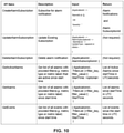
- FIG. 10 illustrates an example of an API that may be used by applications 304 to subscribe to an alarm, unsubscribe from an alarm, get alarm data, and modify an alarm subscription.
- Alarm data adapter 310 can persist alarm notifications into a persistent storage, e.g., time series database (TSDB) 312.
- TSDB 312 may, in some aspects, be implemented using a ClickHouse database or an InfluxDB database, It is possible that the same metric data can be collected by different telemetry protocols such as Simple Network Management Protocol (SNMP), Google Remote Procedure Calls (gRPC), Junos Telemetry Interface (JTI) etc.
- SNMP Simple Network Management Protocol
- gRPC Google Remote Procedure Calls
- JTI Junos Telemetry Interface
- FIG. 8 An example of an alarm rule notification that has been normalized is presented in FIG. 8 .
- other available instances of the service can be to process the workload of the failed instance.
- a new instance of alarm data adapter 310 can be automatically spawned in the case that an older instance crashes.
- Alarm notifier 306 can notify a subscribing application 304 of an alarm via a notification channel established between the alarm notifier 306 and the subscribing application 304.
- the notification channel can be a gRPC streaming channel, a slack application, an interprocess communication mechanism etc.
- Alarm notifier 306 can identify the metric and specific resource for which the notification is generated.
- a set of labels may be present that provides the context for the alarm notifications. Labels can be added dynamically to include metadata information about the metric data for which alarm rule notifications are generated.
- alarm service 140 may monitor itself to facilitate fault tolerance and dynamic scaling.
- alarm service 140 may monitor resource utilization such as processor and memory usage along with other metrics such as queue size which may be specific to a particular component of the alarm service.
- the alarm service may periodically or continuously monitor health metrics that can indicate if alarm service 140 is becoming bottleneck for a given load, thereby causing a new instance of the component that has become a bottleneck to be spawned (e.g., created).
- a set of rules may be defined to monitor the health metrics for a given service and are then used to make decisions for creating new microservice instances for scaling up alarm service capability. Similarly, the same mechanism is used to determine if load conditions are low enough to allow scaling down alarm service capability.
- FIG. 11 illustrates rules and health metrics that can be used for scaling up or down various components and services of alarm service 140.
- one or more of the services described above that are part of alarm service 140 can be implemented as a microservice.
- the microservices that make up alarm service 140 may be loosely coupled with one or more other microservices of alarm service 140 and may implement lightweight protocols to communicate between microservices.
- one or more of the services described above may be implemented as Kubernetes deployment constructs, including pods and containers.
- Alarm service 140 may be implemented as any suitable computing system, such as one or more server computers, workstations, mainframes, appliances, cloud computing systems, and/or other computing systems that may be capable of performing operations and/or functions described in accordance with one or more aspects of the present disclosure.
- alarm service 140 represents a cloud computing system, server farm, and/or server cluster (or portion thereof) that provides services to client devices and other devices or systems.
- alarm service 140 may represent or be implemented through one or more virtualized compute instances (e.g., virtual machines, containers) of a data center, cloud computing system, server farm, and/or server cluster.
- Modules illustrated in FIGS. 2 and 3 may perform operations described using software, hardware, firmware, or a mixture of hardware, software, and firmware residing in and/or executing at one or more computing devices.
- a computing device may execute one or more of such modules with multiple processors or multiple devices.
- a computing device may execute one or more of such modules as a virtual machine executing on underlying hardware.
- One or more of such modules may execute as one or more services of an operating system or computing platform.
- One or more of such modules may execute as one or more executable programs at an application layer of a computing platform.
- functionality provided by a module could be implemented by a dedicated hardware device.
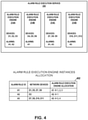
- FIG. 4 is a conceptual diagram illustrating an example allocation of alarms and network devices to alarm rule execution engines in accordance with one or more aspects of the present disclosure.
- alarm execution rule service 332 includes four instances of alarm rule execution engine, 214A, 214B, 214C and 214D.
- Table 402 illustrates the allocation of alarm rules and network devices to alarm rule execution engines in this example.
- An alarm rule (A1) instance is created for network devices D1, D5, D7, D8. As shown in FIG.
- device D1 is allocated to alarm rule execution engine 214A
- device D5 is allocated to alarm rule execution engine 214B
- devices D7, D8 are allocated to alarm rule execution engine 214C.
- alarm A1 is assigned to alarm rule execution engines 214A, 214B and 214C for alarm rule processing.
- Alarm rule A2 only applies to device D2, thus alarm rule A2 is only allocated to alarm rule execution engine 214A.
- Alarm rule A3 applies to devices D7, D8, D10 and D11 and is allocated to alarm rule execution engines 214C and 214D.
- alarm rule programmer 221 is configured to allocate all the rules for a given network device to the same instance of alarm rule execution engine 214. Such an allocation can facilitate distributing the load of alarm rule processing across multiple instances of alarm rule execution engines 214, thereby resulting in a horizontally stable alarm service 140.
- alarm notification subscription service 208 can send periodic alarm notifications for as long as conditions satisfying the alarm rule persists.
- alert mode alarm notification subscription service 208 can send an alarm notification when there is a transition in alarm status. For example, when the alarm rule conditions are satisfied, then alarm notification subscription service 208can send an 'active' notification. No further notifications will be sent as long as the alarm rule conditions stay the same. If alarm rule conditions are no longer met, alarm notification subscription service 208 can send an "inactive" notification. Thus, alert mode may be less "noisy" than event mode.
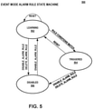
- FIG. 5 is a conceptual diagram illustrating an event mode alarm rule state machine in accordance with one or more aspects of the present disclosure.
- the initial state may be set to learning state 502.
- the state may revert to learning state 502.
- event output is logged, and the state of the event rule may be set to triggered 504.
- the log of the event can include information that identifies the rule for which event is fired and specific conditions that are met for the notification.
- the notification may include a summary of potentially anomalous time series samples that were observed during rule processing.
- the triggered state 504 is an indicator that the rule match criteria was met at a particular instant, and thus the rule fired.
- rule matching is not performed, and the event rule state may be set to disabled 506.
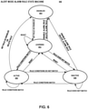
- FIG. 6 is a conceptual diagram illustrating an alert mode alarm rule state machine in accordance with one or more aspects of the present disclosure.
- the initial state of the alert rule may be set to learning 602.
- the alert rule may be set to a state of disabled 604.
- the state of the alert rule may be set to learning 602.
- the alert rule state may be set to active 606 and output may be logged.
- a rule may state in the active 606 state for as long as the telemetry data continues to match the rule criteria.
- an additional alert may be logged with the updated metadata, and the alert rule state may remain as active 606.
- a rule R1 may be active because two interfaces, Interface 1 and Interface2 are down. Later, rule R1 may be active because another interface, Interface3 is down in addition to Interface 1 and Interface2. In such cases, the metadata has changed, and an additional notification may be sent to indicate that the rule R1 is still active, but the reason for activation may have changed.
- the output may be logged with an alert rule state of inactive 608.
- the alert rule may remain in the inactive 608 state until telemetry data matches the rule criteria. In any state except for disabled 604, if the alert rule is reset, the state of the alert rule may be set to learning 602.
- FIG. 7 is a flow diagram illustrating operations performed by components of an example alarm service 140 in accordance with one or more aspects of the present disclosure.
- FIG. 7 is described herein within the context of alarm service 140 of FIGS. 1 , 2 and 3 .
- operations described in FIG. 7 may be performed by one or more other components, modules, systems, or devices.
- operations described in connection with FIG. 7 may be merged, performed in a difference sequence, omitted, or may encompass additional operations not specifically illustrated or described.
- the techniques described in FIG. 7 may be used to facilitate an alarm service that is easy to configure and is scalable.
- devices are allocated to instances of an alarm rule execution engine (702).
- the devices may be allocated evenly or by another suitable heuristic.
- An application such as an EMS application 302 ( FIG. 3 ), may provide an alarm intent with respect to an alarm to be provisioned by an alarm service (704).
- an alarm intent may be a high level description of an alarm.
- An alarm rule intent compiler of the alarm service can translate the alarm intent into one or more rules that may include specific telemetry data, criteria associated with the data, and devices that the alarm is to apply to (706). The one or more rules can be designed to implement the alarm intent received by the alarm service.
- the alarm service may determine devices associated with or specified by the rules generated at 706 (708).
- the rules generated by the alarm rule intent compiler can be provided to one or more instances of an alarm rule programmer.
- the alarm rule programmer can assign the rules to one or more instances of an alarm rule execution engine (710).
- the alarm rule programmer assigns rules based on devices associated with instances of the alarm rule execution engine so as to allocate all rules that are associated with the same device to the same alarm rule execution engine.
- alarm rules may be allocated to an alarm rule execution engine based on the load currently experienced by the alarm rule execution engine. For example, a rule may be allocated to an alarm rule execution engine that has a relatively lighter load.
- Multiple rules can be allocated to the same alarm rule execution engine.
- the same rule may be allocated to different execution engine instances each focused on alarm processing for a specific subset of network devices for a given rule.
- An alarm rules controller can register devices specified in the one or more rules with a telemetry service to start collecting telemetry data for the metrics specified in the one or more rules (712). In some aspects, the alarm rule controller selects an appropriate protocol to register along with the device.
- the alarm rule execution engine(s) 214 upon receiving a rule, can subscribe to a telemetry subscription service for receiving desired telemetry for the alarm rules allocated to the alarm rule execution engine (714).
- the alarm rule execution engine(s) 214 begin receiving telemetry data for metrics that the alarm rule execution engine has subscribed to (716).
- Each instance of alarm rule execution engine 214 processes the rules assigned to the instance (718), and determines if the telemetry data matches the criteria specified in the one or more rules that define an alarm (718).
- an alarm rule execution engine 214 performs a sliding window analysis with respect to the telemetry data and the rule criteria. For example, the alarm rule execution engine may determine if the telemetry data matches rule criteria over a window of time that progresses (e.g., slides) as time passes. The alarm associated with the rules can be triggered if the telemetry data matches the rule criteria for all or a specified portion of the sliding window.
- the alarm service If the telemetry data matches the criteria specified by the alarm rules ("YES" branch of 720), the alarm service outputs an indication of the alarm. For example, the alarm service may notify subscribing applications of the alarm condition.
- the alarm rule execution engine 214 can then wait to receive further telemetry data to be processed according to the rules (return to 716)
- alarm rule execution engine can wait for the arrival of further telemetry data to be processed according to the rules (return to 716).
- one or more implementations of various systems, devices, and/or components may be described with reference to specific Figures, such systems, devices, and/or components may be implemented in a number of different ways.
- one or more devices illustrated in the Figures herein e.g., Figure 1 and/or Figure 2
- one or more components illustrated as separate components may alternatively be implemented as a single component.
- one or more devices illustrated in the Figures herein as a single device may alternatively be implemented as multiple devices; one or more components illustrated as a single component may alternatively be implemented as multiple components.
- Each of such multiple devices and/or components may be directly coupled via wired or wireless communication and/or remotely coupled via one or more networks.
- one or more modules or components may interact with and/or operate in conjunction with one another so that, for example, one module acts as a service or an extension of another module.
- each module, data store, component, program, executable, data item, functional unit, or other item illustrated within a storage device may include multiple components, sub-components, modules, sub-modules, data stores, and/or other components or modules or data stores not illustrated.
- one or more devices or components that may be illustrated in various Figures herein may alternatively be implemented as part of another device or component not shown in such Figures. In this and other ways, some of the functions described herein may be performed via distributed processing by two or more devices or components.
- Each module, data store, component, program, executable, data item, functional unit, or other item illustrated within a storage device may be implemented in various ways.
- each module, data store, component, program, executable, data item, functional unit, or other item illustrated within a storage device may be implemented as a downloadable or pre-installed application or "app.”
- each module, data store, component, program, executable, data item, functional unit, or other item illustrated within a storage device may be implemented as part of an operating system executed on a computing device.
- Computer-readable media may include computer-readable storage media, which corresponds to a tangible medium such as data storage media, or communication media including any medium that facilitates transfer of a computer program from one place to another (e.g., pursuant to a communication protocol).
- computer-readable media generally may correspond to (1) tangible computer-readable storage media, which is non-transitory or (2) a communication medium such as a signal or carrier wave.
- Data storage media may be any available media that can be accessed by one or more computers or one or more processors to retrieve instructions, code and/or data structures for implementation of the techniques described in this disclosure.
- a computer program product may include a computer-readable medium.
- such computer-readable storage media can include RAM, ROM, EEPROM, CD-ROM or other optical disk storage, magnetic disk storage, or other magnetic storage devices, flash memory, or any other medium that can be used to store desired program code in the form of instructions or data structures and that can be accessed by a computer.
- any connection is properly termed a computer-readable medium.
- a computer-readable medium For example, if instructions are transmitted from a website, server, or other remote source using a coaxial cable, fiber optic cable, twisted pair, digital subscriber line (DSL), or wireless technologies such as infrared, radio, and microwave, then the coaxial cable, fiber optic cable, twisted pair, DSL, or wireless technologies such as infrared, radio, and microwave are included in the definition of medium.
- DSL digital subscriber line
- Disk and disc includes compact disc (CD), laser disc, optical disc, digital versatile disc (DVD), floppy disk and Blu-ray disc, where disks usually reproduce data magnetically, while discs reproduce data optically with lasers. Combinations of the above should also be included within the scope of computer-readable media.
- a computer readable medium may include non-transitory type media such as physical storage media including storage discs and solid state devices.
- a computer readable medium may also or alternatively include transient media such as carrier signals and transmission media.
- a computer-readable storage medium is defined herein as a non-transitory memory device.
- a memory device includes memory space within a single physical storage device or memory space spread across multiple physical storage devices.
- processors such as one or more digital signal processors (DSPs), general purpose microprocessors, application specific integrated circuits (ASICs), field programmable logic arrays (FPGAs), or other equivalent integrated or discrete logic circuitry.
- DSPs digital signal processors
- ASICs application specific integrated circuits
- FPGAs field programmable logic arrays
- processors may each refer to any of the foregoing structure or any other structure suitable for implementation of the techniques described.
- the functionality described may be provided within dedicated hardware and/or software modules. Also, the techniques could be fully implemented in one or more circuits or logic elements.
- the techniques of this disclosure may be implemented in a wide variety of devices or apparatuses, including a wireless handset, a mobile or non-mobile computing device, a wearable or non-wearable computing device, an integrated circuit (IC) or a set of ICs (e.g., a chip set).
- IC integrated circuit
- Various components, modules, or units are described in this disclosure to emphasize functional aspects of devices configured to perform the disclosed techniques, but do not necessarily require realization by different hardware units. Rather, as described above, various units may be combined in a hardware unit or provided by a collection of interoperating hardware units, including one or more processors as described above, in conjunction with suitable software and/or firmware
- An alarm rule compiler can receive the intent and translate the high level intent into one or more lower level rules that can be programmatically processed by multiple alarm rule execution engines.
- Devices in a network system can be associated with alarm rule execution engines in a distributed manner. For example, devices in a network can be associated with different instances of an alarm rule execution engine, thus distributing the resource usage for obtaining telemetry data and processing alarms with respect to the devices in a network across multiple alarm rule execution engines.
Landscapes
- Engineering & Computer Science (AREA)
- Computer Networks & Wireless Communication (AREA)
- Signal Processing (AREA)
- Software Systems (AREA)
- Theoretical Computer Science (AREA)
- Computer Vision & Pattern Recognition (AREA)
- Artificial Intelligence (AREA)
- Databases & Information Systems (AREA)
- Evolutionary Computation (AREA)
- Medical Informatics (AREA)
- General Physics & Mathematics (AREA)
- General Engineering & Computer Science (AREA)
- Physics & Mathematics (AREA)
- Data Exchanges In Wide-Area Networks (AREA)
- Debugging And Monitoring (AREA)
Applications Claiming Priority (1)
| Application Number | Priority Date | Filing Date | Title |
|---|---|---|---|
| US16/947,927 US11336504B2 (en) | 2020-08-24 | 2020-08-24 | Intent-based distributed alarm service |
Publications (2)
| Publication Number | Publication Date |
|---|---|
| EP3961985A1 true EP3961985A1 (fr) | 2022-03-02 |
| EP3961985B1 EP3961985B1 (fr) | 2024-07-10 |
Family
ID=73448902
Family Applications (1)
| Application Number | Title | Priority Date | Filing Date |
|---|---|---|---|
| EP20207488.6A Active EP3961985B1 (fr) | 2020-08-24 | 2020-11-13 | Alarme de service distribué à base d'intention |
Country Status (3)
| Country | Link |
|---|---|
| US (2) | US11336504B2 (fr) |
| EP (1) | EP3961985B1 (fr) |
| CN (1) | CN114189425B (fr) |
Families Citing this family (7)
| Publication number | Priority date | Publication date | Assignee | Title |
|---|---|---|---|---|
| US11336504B2 (en) | 2020-08-24 | 2022-05-17 | Juniper Networks, Inc. | Intent-based distributed alarm service |
| US11815999B2 (en) * | 2021-11-29 | 2023-11-14 | Vmware, Inc. | Optimized alarm state restoration through categorization |
| CN115048466B (zh) * | 2022-05-10 | 2025-05-06 | 浙江吉利控股集团有限公司 | 一种数据分析方法、系统、终端及存储介质 |
| US20230421374A1 (en) * | 2022-06-28 | 2023-12-28 | Intel Corporation | Concept for a telemetry hub for microservices |
| CN119422353A (zh) * | 2022-06-30 | 2025-02-11 | 瞻博网络公司 | 用于自动化的应用到网络根本原因分析的框架 |
| US20240179121A1 (en) | 2022-11-30 | 2024-05-30 | Juniper Networks, Inc. | Intelligent Firewall Flow Processor |
| CN117155772B (zh) * | 2023-10-27 | 2024-01-30 | 广州嘉为科技有限公司 | 一种告警信息丰富方法、装置、设备及存储介质 |
Citations (4)
| Publication number | Priority date | Publication date | Assignee | Title |
|---|---|---|---|---|
| US20040117407A1 (en) * | 2002-12-16 | 2004-06-17 | Manoj Kumar | Resource and data administration technologies for IT non-experts |
| US20170331669A1 (en) * | 2016-05-11 | 2017-11-16 | Cisco Technology, Inc. | Virtualized network management protocols |
| US20180278459A1 (en) * | 2017-03-27 | 2018-09-27 | Cisco Technology, Inc. | Sharding Of Network Resources In A Network Policy Platform |
| EP3382543A1 (fr) * | 2017-03-29 | 2018-10-03 | Juniper Networks, Inc. | Surveillance de micro-niveau, visibilité et commande de ressources partagées internes à un processeur d'une machine hôte pour un environnement virtuel |
Family Cites Families (48)
| Publication number | Priority date | Publication date | Assignee | Title |
|---|---|---|---|---|
| US7418426B1 (en) * | 2002-05-20 | 2008-08-26 | Microsoft Corporation | System and method providing rules driven subscription event processing |
| ZA200506089B (en) * | 2004-09-01 | 2007-04-25 | Microsoft Corp | Reader application markup language schema |
| ITMI20111209A1 (it) * | 2011-06-30 | 2012-12-31 | Ibm | Monitoraggio a livello utente in un ambiente di elaborazione a nuvola |
| US8924581B1 (en) * | 2012-03-14 | 2014-12-30 | Amazon Technologies, Inc. | Managing data transfer using streaming protocols |
| US9356871B2 (en) * | 2013-03-15 | 2016-05-31 | Cisco Technology, Inc. | Programmable management engine for networks |
| US9590880B2 (en) * | 2013-08-07 | 2017-03-07 | Microsoft Technology Licensing, Llc | Dynamic collection analysis and reporting of telemetry data |
| US10878323B2 (en) * | 2014-02-28 | 2020-12-29 | Tyco Fire & Security Gmbh | Rules engine combined with message routing |
| US9729383B2 (en) * | 2014-10-15 | 2017-08-08 | Ayla Networks, Inc. | Flexible rules engine for managing connected consumer devices |
| US9256467B1 (en) * | 2014-11-11 | 2016-02-09 | Amazon Technologies, Inc. | System for managing and scheduling containers |
| US10069699B2 (en) * | 2015-02-26 | 2018-09-04 | Nippon Telegraph And Telephone Corporation | Monitoring device information analyzing device and method, and non-transitory storage medium storing program |
| US10075377B1 (en) * | 2015-04-23 | 2018-09-11 | Cisco Technology, Inc. | Statistical collection in a network switch natively configured as a load balancer |
| US10530688B2 (en) * | 2015-06-17 | 2020-01-07 | Extreme Networks, Inc. | Configuration of load-sharing components of a network visibility router in a network visibility system |
| DE202015005019U1 (de) * | 2015-07-18 | 2016-10-20 | Rudolf King | Methode zur Anbindung und Nutzung von externen Serverkapazitäten bei mobilen persönlichen und anderen Sicherheitssystemen und Trennung von Sensoren, Funktionsbereichen und Rechenkapazitäten mittels Alarmverlagerung auf externe Computer und Server |
| US9843474B2 (en) * | 2015-12-23 | 2017-12-12 | Intel Corporation | Telemetry adaptation |
| CN105653425B (zh) * | 2015-12-28 | 2018-10-19 | 中国民航信息网络股份有限公司 | 基于复杂事件处理引擎的监控系统 |
| US10606627B2 (en) * | 2016-02-12 | 2020-03-31 | Nutanix, Inc. | Alerts analysis for a virtualization environment |
| US10135837B2 (en) * | 2016-05-17 | 2018-11-20 | Amazon Technologies, Inc. | Versatile autoscaling for containers |
| US10868743B2 (en) * | 2016-06-01 | 2020-12-15 | Intel Corporation | System and method for providing fast platform telemetry data |
| US10135705B2 (en) * | 2016-06-30 | 2018-11-20 | Rockwell Automation Technologies, Inc. | Industrial internet of things data pipeline for a data lake |
| CN109906462A (zh) * | 2016-09-09 | 2019-06-18 | 瑞典爱立信有限公司 | 用于大规模系统中的策略控制的分析数据收集的技术 |
| EP3327637B1 (fr) * | 2016-11-25 | 2023-05-10 | Accenture Global Solutions Limited | Structure de réduction de défaut à la demande |
| US10612807B2 (en) * | 2017-01-20 | 2020-04-07 | Lennox Industries Inc. | HVAC, refrigeration, and automation equipment management |
| US20180255099A1 (en) * | 2017-03-02 | 2018-09-06 | Microsoft Technology Licensing, Llc | Security and compliance alerts based on content, activities, and metadata in cloud |
| US20180262454A1 (en) * | 2017-03-08 | 2018-09-13 | Linkedin Corporation | Network routing using a publish-subscribe messaging system |
| US10594560B2 (en) * | 2017-03-27 | 2020-03-17 | Cisco Technology, Inc. | Intent driven network policy platform |
| US10764141B2 (en) * | 2017-03-27 | 2020-09-01 | Cisco Technology, Inc. | Network agent for reporting to a network policy system |
| US10868742B2 (en) * | 2017-03-29 | 2020-12-15 | Juniper Networks, Inc. | Multi-cluster dashboard for distributed virtualization infrastructure element monitoring and policy control |
| US10083590B1 (en) * | 2017-05-05 | 2018-09-25 | Vmware, Inc. | Encouraging alert responsiveness |
| US10848839B2 (en) * | 2017-06-09 | 2020-11-24 | American Megatrends International, Llc | Out-of-band telemetry data collection |
| US10484255B2 (en) * | 2017-06-19 | 2019-11-19 | Cisco Technology, Inc. | Trustworthiness index computation in a network assurance system based on data source health monitoring |
| US11386058B2 (en) * | 2017-09-29 | 2022-07-12 | Oracle International Corporation | Rule-based autonomous database cloud service framework |
| US20190140906A1 (en) * | 2017-11-09 | 2019-05-09 | International Business Machines Corporation | Dynamically optimizing internet of things device configuration rules via a gateway |
| US10725464B2 (en) * | 2018-03-22 | 2020-07-28 | Fisher-Rosemount Systems, Inc. | Systems and methods for managing alerts associated with devices of a process control system |
| US10819560B2 (en) * | 2018-03-29 | 2020-10-27 | Servicenow, Inc. | Alert management system and method of using alert context-based alert rules |
| US10567220B2 (en) * | 2018-05-07 | 2020-02-18 | Vmware, Inc. | Distributed rules engine for processing events associated with internet of things devices |
| US11706080B2 (en) * | 2018-06-07 | 2023-07-18 | Vmware, Inc. | Providing dynamic serviceability for software-defined data centers |
| CN109086894A (zh) * | 2018-07-06 | 2018-12-25 | 西安热工研究院有限公司 | 一种面向区域发电公司的报警消息中心系统 |
| CA3050195A1 (fr) * | 2018-07-19 | 2020-01-19 | Bank Of Montreal | Systemes et methodes de services d`alerte |
| JP7190837B2 (ja) * | 2018-07-31 | 2022-12-16 | キヤノン株式会社 | 中継装置、制御方法、及び、プログラム |
| CN108989132A (zh) * | 2018-08-24 | 2018-12-11 | 深圳前海微众银行股份有限公司 | 故障告警处理方法、系统及计算机可读存储介质 |
| CN111294217B (zh) * | 2018-12-06 | 2022-08-19 | 云智慧(北京)科技有限公司 | 告警分析方法、装置、系统及存储介质 |
| US10887158B2 (en) * | 2019-01-31 | 2021-01-05 | Rubrik, Inc. | Alert dependency checking |
| US11070421B2 (en) * | 2019-03-19 | 2021-07-20 | Microsoft Technology Licensing, Llc | Combined registration and telemetry reporting |
| US10970060B2 (en) * | 2019-07-15 | 2021-04-06 | Vmware, Inc. | IoT endpoint metrics |
| CN110401570B (zh) * | 2019-08-06 | 2022-09-27 | 中国联合网络通信集团有限公司 | 告警方法、装置、系统、设备及可读存储介质 |
| US11189382B2 (en) * | 2020-01-02 | 2021-11-30 | Vmware, Inc. | Internet of things (IoT) hybrid alert and action evaluation |
| US11336504B2 (en) | 2020-08-24 | 2022-05-17 | Juniper Networks, Inc. | Intent-based distributed alarm service |
| US12039355B2 (en) | 2020-08-24 | 2024-07-16 | Juniper Networks, Inc. | Intent-based telemetry collection service with supported telemetry protocol in a virtualized computing infrastructure |
-
2020
- 2020-08-24 US US16/947,927 patent/US11336504B2/en active Active
- 2020-11-13 EP EP20207488.6A patent/EP3961985B1/fr active Active
- 2020-11-13 CN CN202011272347.3A patent/CN114189425B/zh active Active
-
2022
- 2022-03-31 US US17/657,383 patent/US11765014B2/en active Active
Patent Citations (4)
| Publication number | Priority date | Publication date | Assignee | Title |
|---|---|---|---|---|
| US20040117407A1 (en) * | 2002-12-16 | 2004-06-17 | Manoj Kumar | Resource and data administration technologies for IT non-experts |
| US20170331669A1 (en) * | 2016-05-11 | 2017-11-16 | Cisco Technology, Inc. | Virtualized network management protocols |
| US20180278459A1 (en) * | 2017-03-27 | 2018-09-27 | Cisco Technology, Inc. | Sharding Of Network Resources In A Network Policy Platform |
| EP3382543A1 (fr) * | 2017-03-29 | 2018-10-03 | Juniper Networks, Inc. | Surveillance de micro-niveau, visibilité et commande de ressources partagées internes à un processeur d'une machine hôte pour un environnement virtuel |
Also Published As
| Publication number | Publication date |
|---|---|
| EP3961985B1 (fr) | 2024-07-10 |
| US11765014B2 (en) | 2023-09-19 |
| CN114189425A (zh) | 2022-03-15 |
| US11336504B2 (en) | 2022-05-17 |
| US20220060369A1 (en) | 2022-02-24 |
| US20220224586A1 (en) | 2022-07-14 |
| CN114189425B (zh) | 2024-11-15 |
Similar Documents
| Publication | Publication Date | Title |
|---|---|---|
| US12039355B2 (en) | Intent-based telemetry collection service with supported telemetry protocol in a virtualized computing infrastructure | |
| EP3961985B1 (fr) | Alarme de service distribué à base d'intention | |
| CN112395041B (zh) | 底层-覆盖相关 | |
| US11451450B2 (en) | Scalable control plane for telemetry data collection within a distributed computing system | |
| EP4161016A1 (fr) | Stockage de modifications de données de configuration pour effectuer une analyse de cause profonde pour des erreurs dans un réseau de dispositifs de réseau gérés | |
| US11765120B2 (en) | Message queue architecture and interface for a multi-application platform | |
| US11520621B2 (en) | Computational instance batching and automation orchestration based on resource usage and availability | |
| US9563459B2 (en) | Creating multiple diagnostic virtual machines to monitor allocated resources of a cluster of hypervisors | |
| US20220030055A1 (en) | Bidirectional Communication Clusters | |
| CN113867884B (zh) | 用于计算机网络的方法和系统及存储介质 | |
| US11870669B2 (en) | At-scale telemetry using interactive matrix for deterministic microservices performance | |
| CN113867885A (zh) | 用于应用程序流监控的方法、计算系统和计算机可读介质 | |
| US10892940B2 (en) | Scalable statistics and analytics mechanisms in cloud networking | |
| CN113923122A (zh) | 得出网络设备和主机连接 | |
| US11403200B2 (en) | Provisioning resources for monitoring hosts based on defined functionalities of hosts | |
| US20260093517A1 (en) | Coordinating data collectors of managed computing networks |
Legal Events
| Date | Code | Title | Description |
|---|---|---|---|
| PUAI | Public reference made under article 153(3) epc to a published international application that has entered the european phase |
Free format text: ORIGINAL CODE: 0009012 |
|
| STAA | Information on the status of an ep patent application or granted ep patent |
Free format text: STATUS: THE APPLICATION HAS BEEN PUBLISHED |
|
| AK | Designated contracting states |
Kind code of ref document: A1 Designated state(s): AL AT BE BG CH CY CZ DE DK EE ES FI FR GB GR HR HU IE IS IT LI LT LU LV MC MK MT NL NO PL PT RO RS SE SI SK SM TR |
|
| STAA | Information on the status of an ep patent application or granted ep patent |
Free format text: STATUS: REQUEST FOR EXAMINATION WAS MADE |
|
| 17P | Request for examination filed |
Effective date: 20220902 |
|
| RBV | Designated contracting states (corrected) |
Designated state(s): AL AT BE BG CH CY CZ DE DK EE ES FI FR GB GR HR HU IE IS IT LI LT LU LV MC MK MT NL NO PL PT RO RS SE SI SK SM TR |
|
| REG | Reference to a national code |
Ref country code: DE Ref legal event code: R079 Ref country code: DE Ref legal event code: R079 Ref document number: 602020033667 Country of ref document: DE Free format text: PREVIOUS MAIN CLASS: H04L0012240000 Ipc: H04L0041068100 |
|
| GRAP | Despatch of communication of intention to grant a patent |
Free format text: ORIGINAL CODE: EPIDOSNIGR1 |
|
| STAA | Information on the status of an ep patent application or granted ep patent |
Free format text: STATUS: GRANT OF PATENT IS INTENDED |
|
| INTG | Intention to grant announced |
Effective date: 20240202 |
|
| RIC1 | Information provided on ipc code assigned before grant |
Ipc: H04L 43/20 20220101ALI20240122BHEP Ipc: H04L 43/065 20220101ALI20240122BHEP Ipc: H04L 41/40 20220101ALI20240122BHEP Ipc: H04L 41/0681 20220101AFI20240122BHEP |
|
| GRAS | Grant fee paid |
Free format text: ORIGINAL CODE: EPIDOSNIGR3 |
|
| GRAA | (expected) grant |
Free format text: ORIGINAL CODE: 0009210 |
|
| STAA | Information on the status of an ep patent application or granted ep patent |
Free format text: STATUS: THE PATENT HAS BEEN GRANTED |
|
| P01 | Opt-out of the competence of the unified patent court (upc) registered |
Effective date: 20240522 |
|
| AK | Designated contracting states |
Kind code of ref document: B1 Designated state(s): AL AT BE BG CH CY CZ DE DK EE ES FI FR GB GR HR HU IE IS IT LI LT LU LV MC MK MT NL NO PL PT RO RS SE SI SK SM TR |
|
| REG | Reference to a national code |
Ref country code: CH Ref legal event code: EP |
|
| REG | Reference to a national code |
Ref country code: DE Ref legal event code: R096 Ref document number: 602020033667 Country of ref document: DE |
|
| REG | Reference to a national code |
Ref country code: LT Ref legal event code: MG9D |
|
| REG | Reference to a national code |
Ref country code: NL Ref legal event code: MP Effective date: 20240710 |
|
| PG25 | Lapsed in a contracting state [announced via postgrant information from national office to epo] |
Ref country code: PT Free format text: LAPSE BECAUSE OF FAILURE TO SUBMIT A TRANSLATION OF THE DESCRIPTION OR TO PAY THE FEE WITHIN THE PRESCRIBED TIME-LIMIT Effective date: 20241111 |
|
| REG | Reference to a national code |
Ref country code: AT Ref legal event code: MK05 Ref document number: 1703021 Country of ref document: AT Kind code of ref document: T Effective date: 20240710 |
|
| PG25 | Lapsed in a contracting state [announced via postgrant information from national office to epo] |
Ref country code: NL Free format text: LAPSE BECAUSE OF FAILURE TO SUBMIT A TRANSLATION OF THE DESCRIPTION OR TO PAY THE FEE WITHIN THE PRESCRIBED TIME-LIMIT Effective date: 20240710 |
|
| PG25 | Lapsed in a contracting state [announced via postgrant information from national office to epo] |
Ref country code: PT Free format text: LAPSE BECAUSE OF FAILURE TO SUBMIT A TRANSLATION OF THE DESCRIPTION OR TO PAY THE FEE WITHIN THE PRESCRIBED TIME-LIMIT Effective date: 20241111 Ref country code: NL Free format text: LAPSE BECAUSE OF FAILURE TO SUBMIT A TRANSLATION OF THE DESCRIPTION OR TO PAY THE FEE WITHIN THE PRESCRIBED TIME-LIMIT Effective date: 20240710 |
|
| PG25 | Lapsed in a contracting state [announced via postgrant information from national office to epo] |
Ref country code: NO Free format text: LAPSE BECAUSE OF FAILURE TO SUBMIT A TRANSLATION OF THE DESCRIPTION OR TO PAY THE FEE WITHIN THE PRESCRIBED TIME-LIMIT Effective date: 20241010 |
|
| PG25 | Lapsed in a contracting state [announced via postgrant information from national office to epo] |
Ref country code: GR Free format text: LAPSE BECAUSE OF FAILURE TO SUBMIT A TRANSLATION OF THE DESCRIPTION OR TO PAY THE FEE WITHIN THE PRESCRIBED TIME-LIMIT Effective date: 20241011 Ref country code: FI Free format text: LAPSE BECAUSE OF FAILURE TO SUBMIT A TRANSLATION OF THE DESCRIPTION OR TO PAY THE FEE WITHIN THE PRESCRIBED TIME-LIMIT Effective date: 20240710 Ref country code: PL Free format text: LAPSE BECAUSE OF FAILURE TO SUBMIT A TRANSLATION OF THE DESCRIPTION OR TO PAY THE FEE WITHIN THE PRESCRIBED TIME-LIMIT Effective date: 20240710 |
|
| PG25 | Lapsed in a contracting state [announced via postgrant information from national office to epo] |
Ref country code: BG Free format text: LAPSE BECAUSE OF FAILURE TO SUBMIT A TRANSLATION OF THE DESCRIPTION OR TO PAY THE FEE WITHIN THE PRESCRIBED TIME-LIMIT Effective date: 20240710 |
|
| PG25 | Lapsed in a contracting state [announced via postgrant information from national office to epo] |
Ref country code: LV Free format text: LAPSE BECAUSE OF FAILURE TO SUBMIT A TRANSLATION OF THE DESCRIPTION OR TO PAY THE FEE WITHIN THE PRESCRIBED TIME-LIMIT Effective date: 20240710 |
|
| PG25 | Lapsed in a contracting state [announced via postgrant information from national office to epo] |
Ref country code: IS Free format text: LAPSE BECAUSE OF FAILURE TO SUBMIT A TRANSLATION OF THE DESCRIPTION OR TO PAY THE FEE WITHIN THE PRESCRIBED TIME-LIMIT Effective date: 20241110 Ref country code: AT Free format text: LAPSE BECAUSE OF FAILURE TO SUBMIT A TRANSLATION OF THE DESCRIPTION OR TO PAY THE FEE WITHIN THE PRESCRIBED TIME-LIMIT Effective date: 20240710 |
|
| PG25 | Lapsed in a contracting state [announced via postgrant information from national office to epo] |
Ref country code: HR Free format text: LAPSE BECAUSE OF FAILURE TO SUBMIT A TRANSLATION OF THE DESCRIPTION OR TO PAY THE FEE WITHIN THE PRESCRIBED TIME-LIMIT Effective date: 20240710 |
|
| PG25 | Lapsed in a contracting state [announced via postgrant information from national office to epo] |
Ref country code: ES Free format text: LAPSE BECAUSE OF FAILURE TO SUBMIT A TRANSLATION OF THE DESCRIPTION OR TO PAY THE FEE WITHIN THE PRESCRIBED TIME-LIMIT Effective date: 20240710 Ref country code: RS Free format text: LAPSE BECAUSE OF FAILURE TO SUBMIT A TRANSLATION OF THE DESCRIPTION OR TO PAY THE FEE WITHIN THE PRESCRIBED TIME-LIMIT Effective date: 20241010 |
|
| PG25 | Lapsed in a contracting state [announced via postgrant information from national office to epo] |
Ref country code: RS Free format text: LAPSE BECAUSE OF FAILURE TO SUBMIT A TRANSLATION OF THE DESCRIPTION OR TO PAY THE FEE WITHIN THE PRESCRIBED TIME-LIMIT Effective date: 20241010 Ref country code: PL Free format text: LAPSE BECAUSE OF FAILURE TO SUBMIT A TRANSLATION OF THE DESCRIPTION OR TO PAY THE FEE WITHIN THE PRESCRIBED TIME-LIMIT Effective date: 20240710 Ref country code: NO Free format text: LAPSE BECAUSE OF FAILURE TO SUBMIT A TRANSLATION OF THE DESCRIPTION OR TO PAY THE FEE WITHIN THE PRESCRIBED TIME-LIMIT Effective date: 20241010 Ref country code: LV Free format text: LAPSE BECAUSE OF FAILURE TO SUBMIT A TRANSLATION OF THE DESCRIPTION OR TO PAY THE FEE WITHIN THE PRESCRIBED TIME-LIMIT Effective date: 20240710 Ref country code: IS Free format text: LAPSE BECAUSE OF FAILURE TO SUBMIT A TRANSLATION OF THE DESCRIPTION OR TO PAY THE FEE WITHIN THE PRESCRIBED TIME-LIMIT Effective date: 20241110 Ref country code: HR Free format text: LAPSE BECAUSE OF FAILURE TO SUBMIT A TRANSLATION OF THE DESCRIPTION OR TO PAY THE FEE WITHIN THE PRESCRIBED TIME-LIMIT Effective date: 20240710 Ref country code: GR Free format text: LAPSE BECAUSE OF FAILURE TO SUBMIT A TRANSLATION OF THE DESCRIPTION OR TO PAY THE FEE WITHIN THE PRESCRIBED TIME-LIMIT Effective date: 20241011 Ref country code: FI Free format text: LAPSE BECAUSE OF FAILURE TO SUBMIT A TRANSLATION OF THE DESCRIPTION OR TO PAY THE FEE WITHIN THE PRESCRIBED TIME-LIMIT Effective date: 20240710 Ref country code: ES Free format text: LAPSE BECAUSE OF FAILURE TO SUBMIT A TRANSLATION OF THE DESCRIPTION OR TO PAY THE FEE WITHIN THE PRESCRIBED TIME-LIMIT Effective date: 20240710 Ref country code: BG Free format text: LAPSE BECAUSE OF FAILURE TO SUBMIT A TRANSLATION OF THE DESCRIPTION OR TO PAY THE FEE WITHIN THE PRESCRIBED TIME-LIMIT Effective date: 20240710 Ref country code: AT Free format text: LAPSE BECAUSE OF FAILURE TO SUBMIT A TRANSLATION OF THE DESCRIPTION OR TO PAY THE FEE WITHIN THE PRESCRIBED TIME-LIMIT Effective date: 20240710 |
|
| REG | Reference to a national code |
Ref country code: DE Ref legal event code: R097 Ref document number: 602020033667 Country of ref document: DE |
|
| PG25 | Lapsed in a contracting state [announced via postgrant information from national office to epo] |
Ref country code: SM Free format text: LAPSE BECAUSE OF FAILURE TO SUBMIT A TRANSLATION OF THE DESCRIPTION OR TO PAY THE FEE WITHIN THE PRESCRIBED TIME-LIMIT Effective date: 20240710 Ref country code: DK Free format text: LAPSE BECAUSE OF FAILURE TO SUBMIT A TRANSLATION OF THE DESCRIPTION OR TO PAY THE FEE WITHIN THE PRESCRIBED TIME-LIMIT Effective date: 20240710 Ref country code: RO Free format text: LAPSE BECAUSE OF FAILURE TO SUBMIT A TRANSLATION OF THE DESCRIPTION OR TO PAY THE FEE WITHIN THE PRESCRIBED TIME-LIMIT Effective date: 20240710 |
|
| PG25 | Lapsed in a contracting state [announced via postgrant information from national office to epo] |
Ref country code: EE Free format text: LAPSE BECAUSE OF FAILURE TO SUBMIT A TRANSLATION OF THE DESCRIPTION OR TO PAY THE FEE WITHIN THE PRESCRIBED TIME-LIMIT Effective date: 20240710 |
|
| PG25 | Lapsed in a contracting state [announced via postgrant information from national office to epo] |
Ref country code: CZ Free format text: LAPSE BECAUSE OF FAILURE TO SUBMIT A TRANSLATION OF THE DESCRIPTION OR TO PAY THE FEE WITHIN THE PRESCRIBED TIME-LIMIT Effective date: 20240710 |
|
| PG25 | Lapsed in a contracting state [announced via postgrant information from national office to epo] |
Ref country code: SK Free format text: LAPSE BECAUSE OF FAILURE TO SUBMIT A TRANSLATION OF THE DESCRIPTION OR TO PAY THE FEE WITHIN THE PRESCRIBED TIME-LIMIT Effective date: 20240710 Ref country code: IT Free format text: LAPSE BECAUSE OF FAILURE TO SUBMIT A TRANSLATION OF THE DESCRIPTION OR TO PAY THE FEE WITHIN THE PRESCRIBED TIME-LIMIT Effective date: 20240710 |
|
| PLBE | No opposition filed within time limit |
Free format text: ORIGINAL CODE: 0009261 |
|
| STAA | Information on the status of an ep patent application or granted ep patent |
Free format text: STATUS: NO OPPOSITION FILED WITHIN TIME LIMIT |
|
| 26N | No opposition filed |
Effective date: 20250411 |
|
| REG | Reference to a national code |
Ref country code: CH Ref legal event code: PL |
|
| PG25 | Lapsed in a contracting state [announced via postgrant information from national office to epo] |
Ref country code: MC Free format text: LAPSE BECAUSE OF FAILURE TO SUBMIT A TRANSLATION OF THE DESCRIPTION OR TO PAY THE FEE WITHIN THE PRESCRIBED TIME-LIMIT Effective date: 20240710 |
|
| PG25 | Lapsed in a contracting state [announced via postgrant information from national office to epo] |
Ref country code: LU Free format text: LAPSE BECAUSE OF NON-PAYMENT OF DUE FEES Effective date: 20241113 |
|
| REG | Reference to a national code |
Ref country code: CH Ref legal event code: PL |
|
| PG25 | Lapsed in a contracting state [announced via postgrant information from national office to epo] |
Ref country code: CH Free format text: LAPSE BECAUSE OF NON-PAYMENT OF DUE FEES Effective date: 20241130 |
|
| REG | Reference to a national code |
Ref country code: BE Ref legal event code: MM Effective date: 20241130 |
|
| PG25 | Lapsed in a contracting state [announced via postgrant information from national office to epo] |
Ref country code: SE Free format text: LAPSE BECAUSE OF FAILURE TO SUBMIT A TRANSLATION OF THE DESCRIPTION OR TO PAY THE FEE WITHIN THE PRESCRIBED TIME-LIMIT Effective date: 20240710 |
|
| PG25 | Lapsed in a contracting state [announced via postgrant information from national office to epo] |
Ref country code: BE Free format text: LAPSE BECAUSE OF NON-PAYMENT OF DUE FEES Effective date: 20241130 |
|
| PG25 | Lapsed in a contracting state [announced via postgrant information from national office to epo] |
Ref country code: IE Free format text: LAPSE BECAUSE OF NON-PAYMENT OF DUE FEES Effective date: 20241113 |
|
| PGFP | Annual fee paid to national office [announced via postgrant information from national office to epo] |
Ref country code: DE Payment date: 20251022 Year of fee payment: 6 |
|
| PGFP | Annual fee paid to national office [announced via postgrant information from national office to epo] |
Ref country code: GB Payment date: 20251023 Year of fee payment: 6 |
|
| PGFP | Annual fee paid to national office [announced via postgrant information from national office to epo] |
Ref country code: FR Payment date: 20251022 Year of fee payment: 6 |
|
| PG25 | Lapsed in a contracting state [announced via postgrant information from national office to epo] |
Ref country code: HU Free format text: LAPSE BECAUSE OF FAILURE TO SUBMIT A TRANSLATION OF THE DESCRIPTION OR TO PAY THE FEE WITHIN THE PRESCRIBED TIME-LIMIT; INVALID AB INITIO Effective date: 20201113 |
|
| PG25 | Lapsed in a contracting state [announced via postgrant information from national office to epo] |
Ref country code: CY Free format text: LAPSE BECAUSE OF FAILURE TO SUBMIT A TRANSLATION OF THE DESCRIPTION OR TO PAY THE FEE WITHIN THE PRESCRIBED TIME-LIMIT; INVALID AB INITIO Effective date: 20201113 |