EP3961960A2 - Réception du pdsch programmée par un premier pdcch et par un second pdcch en utilisant une supposition qcl - Google Patents
Réception du pdsch programmée par un premier pdcch et par un second pdcch en utilisant une supposition qcl Download PDFInfo
- Publication number
- EP3961960A2 EP3961960A2 EP21192268.7A EP21192268A EP3961960A2 EP 3961960 A2 EP3961960 A2 EP 3961960A2 EP 21192268 A EP21192268 A EP 21192268A EP 3961960 A2 EP3961960 A2 EP 3961960A2
- Authority
- EP
- European Patent Office
- Prior art keywords
- coreset
- tci state
- pdcch
- tci
- pdsch
- Prior art date
- Legal status (The legal status is an assumption and is not a legal conclusion. Google has not performed a legal analysis and makes no representation as to the accuracy of the status listed.)
- Granted
Links
- 238000012544 monitoring process Methods 0.000 claims abstract description 432
- 230000005540 biological transmission Effects 0.000 claims abstract description 164
- 238000000034 method Methods 0.000 claims description 67
- 238000004891 communication Methods 0.000 description 43
- 230000004913 activation Effects 0.000 description 35
- 238000013507 mapping Methods 0.000 description 30
- 238000013468 resource allocation Methods 0.000 description 29
- 230000004044 response Effects 0.000 description 25
- 230000011664 signaling Effects 0.000 description 25
- 238000010586 diagram Methods 0.000 description 20
- 101150069124 RAN1 gene Proteins 0.000 description 15
- 101100355633 Salmo salar ran gene Proteins 0.000 description 15
- 230000000737 periodic effect Effects 0.000 description 15
- 230000002776 aggregation Effects 0.000 description 13
- 238000004220 aggregation Methods 0.000 description 13
- 230000009849 deactivation Effects 0.000 description 12
- 101150014328 RAN2 gene Proteins 0.000 description 10
- 230000008569 process Effects 0.000 description 10
- 230000007704 transition Effects 0.000 description 9
- 238000013461 design Methods 0.000 description 8
- 230000009471 action Effects 0.000 description 7
- 239000011159 matrix material Substances 0.000 description 7
- 238000005259 measurement Methods 0.000 description 6
- 230000007246 mechanism Effects 0.000 description 6
- 238000012545 processing Methods 0.000 description 6
- 230000002441 reversible effect Effects 0.000 description 6
- 235000019527 sweetened beverage Nutrition 0.000 description 6
- 239000013256 coordination polymer Substances 0.000 description 5
- 230000006978 adaptation Effects 0.000 description 4
- 125000004122 cyclic group Chemical group 0.000 description 4
- 238000005516 engineering process Methods 0.000 description 4
- 230000006870 function Effects 0.000 description 4
- 238000009482 thermal adhesion granulation Methods 0.000 description 4
- 101000946053 Homo sapiens Lysosomal-associated transmembrane protein 4A Proteins 0.000 description 3
- 102100034728 Lysosomal-associated transmembrane protein 4A Human genes 0.000 description 3
- 230000003213 activating effect Effects 0.000 description 3
- 238000013459 approach Methods 0.000 description 3
- 230000006399 behavior Effects 0.000 description 3
- 239000000969 carrier Substances 0.000 description 3
- 230000001143 conditioned effect Effects 0.000 description 3
- 230000003287 optical effect Effects 0.000 description 3
- 230000010363 phase shift Effects 0.000 description 3
- 230000009467 reduction Effects 0.000 description 3
- 230000008901 benefit Effects 0.000 description 2
- 238000004590 computer program Methods 0.000 description 2
- 230000001419 dependent effect Effects 0.000 description 2
- 230000007774 longterm Effects 0.000 description 2
- 230000000116 mitigating effect Effects 0.000 description 2
- 238000010295 mobile communication Methods 0.000 description 2
- 239000002245 particle Substances 0.000 description 2
- 238000013146 percutaneous coronary intervention Methods 0.000 description 2
- 238000001228 spectrum Methods 0.000 description 2
- 230000008685 targeting Effects 0.000 description 2
- CSRZQMIRAZTJOY-UHFFFAOYSA-N trimethylsilyl iodide Substances C[Si](C)(C)I CSRZQMIRAZTJOY-UHFFFAOYSA-N 0.000 description 2
- 101000741965 Homo sapiens Inactive tyrosine-protein kinase PRAG1 Proteins 0.000 description 1
- 102100038659 Inactive tyrosine-protein kinase PRAG1 Human genes 0.000 description 1
- 108700026140 MAC combination Proteins 0.000 description 1
- 101150096310 SIB1 gene Proteins 0.000 description 1
- 230000003044 adaptive effect Effects 0.000 description 1
- 230000004931 aggregating effect Effects 0.000 description 1
- 230000001174 ascending effect Effects 0.000 description 1
- 230000009286 beneficial effect Effects 0.000 description 1
- 230000008859 change Effects 0.000 description 1
- 230000000295 complement effect Effects 0.000 description 1
- 230000006835 compression Effects 0.000 description 1
- 238000007906 compression Methods 0.000 description 1
- 238000012790 confirmation Methods 0.000 description 1
- 230000001276 controlling effect Effects 0.000 description 1
- 238000011161 development Methods 0.000 description 1
- 230000018109 developmental process Effects 0.000 description 1
- 230000004069 differentiation Effects 0.000 description 1
- 230000000977 initiatory effect Effects 0.000 description 1
- 238000012986 modification Methods 0.000 description 1
- 230000004048 modification Effects 0.000 description 1
- 230000008520 organization Effects 0.000 description 1
- 239000005022 packaging material Substances 0.000 description 1
- 230000035515 penetration Effects 0.000 description 1
- 238000011084 recovery Methods 0.000 description 1
- 230000001105 regulatory effect Effects 0.000 description 1
- 230000011218 segmentation Effects 0.000 description 1
- 239000004065 semiconductor Substances 0.000 description 1
- 230000007480 spreading Effects 0.000 description 1
- 230000003068 static effect Effects 0.000 description 1
- 230000001360 synchronised effect Effects 0.000 description 1
- 238000012546 transfer Methods 0.000 description 1
Images


Classifications
-
- H—ELECTRICITY
- H04—ELECTRIC COMMUNICATION TECHNIQUE
- H04L—TRANSMISSION OF DIGITAL INFORMATION, e.g. TELEGRAPHIC COMMUNICATION
- H04L5/00—Arrangements affording multiple use of the transmission path
- H04L5/003—Arrangements for allocating sub-channels of the transmission path
- H04L5/0053—Allocation of signaling, i.e. of overhead other than pilot signals
-
- H—ELECTRICITY
- H04—ELECTRIC COMMUNICATION TECHNIQUE
- H04W—WIRELESS COMMUNICATION NETWORKS
- H04W72/00—Local resource management
- H04W72/12—Wireless traffic scheduling
- H04W72/1263—Mapping of traffic onto schedule, e.g. scheduled allocation or multiplexing of flows
- H04W72/1273—Mapping of traffic onto schedule, e.g. scheduled allocation or multiplexing of flows of downlink data flows
-
- H—ELECTRICITY
- H04—ELECTRIC COMMUNICATION TECHNIQUE
- H04B—TRANSMISSION
- H04B17/00—Monitoring; Testing
- H04B17/30—Monitoring; Testing of propagation channels
- H04B17/373—Predicting channel quality or other radio frequency [RF] parameters
-
- H—ELECTRICITY
- H04—ELECTRIC COMMUNICATION TECHNIQUE
- H04L—TRANSMISSION OF DIGITAL INFORMATION, e.g. TELEGRAPHIC COMMUNICATION
- H04L5/00—Arrangements affording multiple use of the transmission path
- H04L5/0001—Arrangements for dividing the transmission path
- H04L5/0003—Two-dimensional division
- H04L5/0005—Time-frequency
- H04L5/0007—Time-frequency the frequencies being orthogonal, e.g. OFDM(A), DMT
-
- H—ELECTRICITY
- H04—ELECTRIC COMMUNICATION TECHNIQUE
- H04L—TRANSMISSION OF DIGITAL INFORMATION, e.g. TELEGRAPHIC COMMUNICATION
- H04L5/00—Arrangements affording multiple use of the transmission path
- H04L5/003—Arrangements for allocating sub-channels of the transmission path
- H04L5/0044—Arrangements for allocating sub-channels of the transmission path allocation of payload
-
- H—ELECTRICITY
- H04—ELECTRIC COMMUNICATION TECHNIQUE
- H04L—TRANSMISSION OF DIGITAL INFORMATION, e.g. TELEGRAPHIC COMMUNICATION
- H04L5/00—Arrangements affording multiple use of the transmission path
- H04L5/003—Arrangements for allocating sub-channels of the transmission path
- H04L5/0078—Timing of allocation
- H04L5/0082—Timing of allocation at predetermined intervals
-
- H—ELECTRICITY
- H04—ELECTRIC COMMUNICATION TECHNIQUE
- H04L—TRANSMISSION OF DIGITAL INFORMATION, e.g. TELEGRAPHIC COMMUNICATION
- H04L5/00—Arrangements affording multiple use of the transmission path
- H04L5/0091—Signaling for the administration of the divided path
-
- H—ELECTRICITY
- H04—ELECTRIC COMMUNICATION TECHNIQUE
- H04W—WIRELESS COMMUNICATION NETWORKS
- H04W72/00—Local resource management
- H04W72/04—Wireless resource allocation
- H04W72/044—Wireless resource allocation based on the type of the allocated resource
- H04W72/0446—Resources in time domain, e.g. slots or frames
-
- H—ELECTRICITY
- H04—ELECTRIC COMMUNICATION TECHNIQUE
- H04W—WIRELESS COMMUNICATION NETWORKS
- H04W72/00—Local resource management
- H04W72/04—Wireless resource allocation
- H04W72/044—Wireless resource allocation based on the type of the allocated resource
- H04W72/0453—Resources in frequency domain, e.g. a carrier in FDMA
-
- H—ELECTRICITY
- H04—ELECTRIC COMMUNICATION TECHNIQUE
- H04W—WIRELESS COMMUNICATION NETWORKS
- H04W72/00—Local resource management
- H04W72/20—Control channels or signalling for resource management
- H04W72/23—Control channels or signalling for resource management in the downlink direction of a wireless link, i.e. towards a terminal
-
- H—ELECTRICITY
- H04—ELECTRIC COMMUNICATION TECHNIQUE
- H04W—WIRELESS COMMUNICATION NETWORKS
- H04W72/00—Local resource management
- H04W72/50—Allocation or scheduling criteria for wireless resources
- H04W72/535—Allocation or scheduling criteria for wireless resources based on resource usage policies
-
- H—ELECTRICITY
- H04—ELECTRIC COMMUNICATION TECHNIQUE
- H04B—TRANSMISSION
- H04B7/00—Radio transmission systems, i.e. using radiation field
- H04B7/02—Diversity systems; Multi-antenna system, i.e. transmission or reception using multiple antennas
- H04B7/04—Diversity systems; Multi-antenna system, i.e. transmission or reception using multiple antennas using two or more spaced independent antennas
- H04B7/06—Diversity systems; Multi-antenna system, i.e. transmission or reception using multiple antennas using two or more spaced independent antennas at the transmitting station
- H04B7/0613—Diversity systems; Multi-antenna system, i.e. transmission or reception using multiple antennas using two or more spaced independent antennas at the transmitting station using simultaneous transmission
- H04B7/0615—Diversity systems; Multi-antenna system, i.e. transmission or reception using multiple antennas using two or more spaced independent antennas at the transmitting station using simultaneous transmission of weighted versions of same signal
- H04B7/0617—Diversity systems; Multi-antenna system, i.e. transmission or reception using multiple antennas using two or more spaced independent antennas at the transmitting station using simultaneous transmission of weighted versions of same signal for beam forming
-
- H—ELECTRICITY
- H04—ELECTRIC COMMUNICATION TECHNIQUE
- H04L—TRANSMISSION OF DIGITAL INFORMATION, e.g. TELEGRAPHIC COMMUNICATION
- H04L5/00—Arrangements affording multiple use of the transmission path
- H04L5/0001—Arrangements for dividing the transmission path
- H04L5/0003—Two-dimensional division
- H04L5/0005—Time-frequency
- H04L5/0007—Time-frequency the frequencies being orthogonal, e.g. OFDM(A), DMT
- H04L5/001—Time-frequency the frequencies being orthogonal, e.g. OFDM(A), DMT the frequencies being arranged in component carriers
-
- H—ELECTRICITY
- H04—ELECTRIC COMMUNICATION TECHNIQUE
- H04L—TRANSMISSION OF DIGITAL INFORMATION, e.g. TELEGRAPHIC COMMUNICATION
- H04L5/00—Arrangements affording multiple use of the transmission path
- H04L5/0001—Arrangements for dividing the transmission path
- H04L5/0014—Three-dimensional division
- H04L5/0023—Time-frequency-space
Definitions
- IP Internet Protocol
- An exemplary network structure is an Evolved Universal Terrestrial Radio Access Network (E-UTRAN).
- E-UTRAN Evolved Universal Terrestrial Radio Access Network
- the E-UTRAN system can provide high data throughput in order to realize the above-noted voice over IP and multimedia services.
- a new radio technology for the next generation e.g., 5G
- 5G next generation
- changes to the current body of 3GPP standard are currently being submitted and considered to evolve and finalize the 3GPP standard.
- the UE monitors a first Physical Downlink Control Channel (PDCCH), via a first spatial Quasi-Colocation (QCL) assumption associated with a first Transmission Configuration Indicator (TCI) state, on a first monitoring occasion of a first Control Resource Set (CORESET).
- the UE monitors a second PDCCH, via a second spatial QCL assumption associated with a second TCI state, on a second monitoring occasion of a second CORESET.
- the UE determines an interval between a last orthogonal frequency-division multiplexing (OFDM) symbol of a reference monitoring occasion and a starting OFDM symbol of a scheduled Physical Downlink Shared Channel (PDSCH), wherein the reference monitoring occasion is a last monitoring occasion of the first monitoring occasion and the second monitoring occasion. Based on the interval being larger than or equal to a threshold, the UE receives the scheduled PDSCH via a third spatial QCL assumption associated with a third TCI state, wherein the third TCI state is determined based on a lowest CORESET identity of a first CORESET identity of the first CORESET and a second CORESET identity of the second CORESET.
- OFDM orthogonal frequency-division multiplexing
- PDSCH Physical Downlink Shared Channel
- the UE monitors a first CORESET, via a first spatial QCL assumption associated with a first TCI state, on a first monitoring occasion, wherein a first PDCCH is associated with the first CORESET.
- the UE monitors a second CORESET, via a second spatial QCL assumption associated with a second TCI state, on a second monitoring occasion, wherein a second PDCCH is associated with the second CORESET, the first PDCCH schedules a PDSCH and the second PDCCH schedules the PDSCH.
- the UE determines an interval between a last OFDM symbol of a reference monitoring occasion and a starting OFDM symbol of the PDSCH, wherein the reference monitoring occasion is a last monitoring occasion of the first monitoring occasion and the second monitoring occasion. Based on the interval being larger than or equal to a threshold, the UE determines the PDSCH via a third spatial QCL assumption associated with a third TCI state, wherein the third TCI state is determined based on a lowest CORESET identity of a first CORESET identity of the first CORESET and a second CORESET identity of the second CORESET.
- Wireless communication systems are widely deployed to provide various types of communication such as voice, data, and so on. These systems may be based on code division multiple access (CDMA), time division multiple access (TDMA), orthogonal frequency division multiple access (OFDMA), 3 rd Generation Partnership Project (3GPP) LTE (Long Term Evolution) wireless access, 3GPP LTE-A or LTE-Advanced (Long Term Evolution Advanced), 3GPP2 UMB (Ultra Mobile Broadband), WiMax, 3GPP NR (New Radio) wireless access for 5G, or some other modulation techniques.
- CDMA code division multiple access
- TDMA time division multiple access
- OFDMA orthogonal frequency division multiple access
- 3GPP 3 rd Generation Partnership Project
- LTE Long Term Evolution
- 3GPP LTE-A or LTE-Advanced Long Term Evolution Advanced
- 3GPP2 UMB User Mobile Broadband
- WiMax Worldwide Interoperability for Microwave Access
- the exemplary wireless communication systems devices described below may be designed to support one or more standards such as the standard offered by a consortium named "3rd Generation Partnership Project" referred to herein as 3GPP, including: 3GPP TS 38.300 V15.8.0 (2019-12 ) 3rd Generation Partnership Project; Technical Specification Group Radio Access Network; NR; NR and NG-RAN Overall Description; Stage 2 (Release 15); R1-1913604 RAN1 agreements for NR_eMIMO, Samsung; 3GPP TS 38.321 V15.8.0 (2019-12 ) 3rd Generation Partnership Project; Technical Specification Group Radio Access Network; NR; Medium Access Control (MAC) protocol specification (Release 15); 3GPP TS 38.331 V15.8.0 (2019-12 ) 3rd Generation Partnership Project; Technical Specification Group Radio Access Network; NR; Radio Resource Control (RRC) protocol specification (Release 15); 3GPP TS 38.211 V15.8.0 (2019-12 ) 3rd Generation Partnership Project; Technical Specification Group Radio Access Network
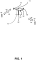
- FIG. 1 presents a multiple access wireless communication system in accordance with one or more embodiments of the disclosure.
- An access network 100 includes multiple antenna groups, one including 104 and 106, another including 108 and 110, and an additional including 112 and 114. In FIG. 1 , only two antennas are shown for each antenna group, however, more or fewer antennas may be utilized for each antenna group.
- Access terminal 116 is in communication with antennas 112 and 114, where antennas 112 and 114 transmit information to access terminal 116 over forward link 120 and receive information from access terminal 116 over reverse link 118.
- AT 122 is in communication with antennas 106 and 108, where antennas 106 and 108 transmit information to AT 122 over forward link 126 and receive information from AT 122 over reverse link 124.
- communication links 118, 120, 124 and 126 may use different frequencies for communication.
- forward link 120 may use a different frequency than that used by reverse link 118.
- antenna groups each may be designed to communicate to access terminals in a sector of the areas covered by access network 100.
- the transmitting antennas of access network 100 may utilize beamforming in order to improve the signal-to-noise ratio of forward links for the different access terminals 116 and 122. Also, an access network using beamforming to transmit to access terminals scattered randomly through its coverage may normally cause less interference to access terminals in neighboring cells than an access network transmitting through a single antenna to its access terminals.
- An access network may be a fixed station or base station used for communicating with the terminals and may also be referred to as an access point, a Node B, a base station, an enhanced base station, an eNodeB (eNB), a Next Generation NodeB (gNB), or some other terminology.
- An access terminal may also be called user equipment (UE), a wireless communication device, terminal, access terminal or some other terminology.
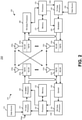
- FIG. 2 presents an embodiment of a transmitter system 210 (also known as the access network) and a receiver system 250 (also known as access terminal (AT) or user equipment (UE)) in a multiple-input and multiple-output (MIMO) system 200.
- a transmitter system 210 also known as the access network
- a receiver system 250 also known as access terminal (AT) or user equipment (UE)
- MIMO multiple-input and multiple-output
- traffic data for a number of data streams may be provided from a data source 212 to a transmit (TX) data processor 214.
- TX transmit
- each data stream is transmitted over a respective transmit antenna.
- TX data processor 214 formats, codes, and interleaves the traffic data for each data stream based on a particular coding scheme selected for that data stream to provide coded data.
- the coded data for each data stream may be multiplexed with pilot data using orthogonal frequency-division multiplexing (OFDM) techniques.
- the pilot data may typically be a known data pattern that is processed in a known manner and may be used at the receiver system to estimate the channel response.
- the multiplexed pilot and coded data for each data stream may then be modulated (i.e., symbol mapped) based on a particular modulation scheme (e.g., binary phase shift keying (BPSK), quadrature phase shift keying (QPSK), M-ary phase shift keying (M-PSK), or M-ary quadrature amplitude modulation (M-QAM)) selected for that data stream to provide modulation symbols.
- BPSK binary phase shift keying
- QPSK quadrature phase shift keying
- M-PSK M-ary phase shift keying
- M-QAM M-ary quadrature amplitude modulation
- the data rate, coding, and/or modulation for each data stream may be determined
- TX MIMO processor 220 may further process the modulation symbols (e.g., for OFDM).
- TX MIMO processor 220 then provides N T modulation symbol streams to N T transmitters (TMTR) 222a through 222t.
- TMTR TX MIMO processor 220 may apply beamforming weights to the symbols of the data streams and to the antenna from which the symbol is being transmitted.
- Each transmitter 222 receives and processes a respective symbol stream to provide one or more analog signals, and further conditions (e.g., amplifies, filters, and/or upconverts) the analog signals to provide a modulated signal suitable for transmission over the MIMO channel.
- N T modulated signals from transmitters 222a through 222t may then be transmitted from N T antennas 224a through 224t, respectively.
- the transmitted modulated signals are received by N R antennas 252a through 252r and the received signal from each antenna 252 may be provided to a respective receiver (RCVR) 254a through 254r.
- Each receiver 254 may condition (e.g., filters, amplifies, and downconverts) a respective received signal, digitize the conditioned signal to provide samples, and/or further process the samples to provide a corresponding "received" symbol stream.
- An RX data processor 260 then receives and/or processes the N R received symbol streams from N R receivers 254 based on a particular receiver processing technique to provide N T "detected" symbol streams.
- the RX data processor 260 may then demodulate, deinterleave, and/or decode each detected symbol stream to recover the traffic data for the data stream.
- the processing by RX data processor 260 may be complementary to that performed by TX MIMO processor 220 and TX data processor 214 at transmitter system 210.
- a processor 270 may periodically determine which pre-coding matrix to use (discussed below). Processor 270 formulates a reverse link message comprising a matrix index portion and a rank value portion.
- the reverse link message may comprise various types of information regarding the communication link and/or the received data stream.
- the reverse link message may then be processed by a TX data processor 238, which may also receive traffic data for a number of data streams from a data source 236, modulated by a modulator 280, conditioned by transmitters 254a through 254r, and/or transmitted back to transmitter system 210.
- the modulated signals from receiver system 250 are received by antennas 224, conditioned by receivers 222, demodulated by a demodulator 240, and processed by a RX data processor 242 to extract the reserve link message transmitted by the receiver system 250.
- Processor 230 may then determine which pre-coding matrix to use for determining the beamforming weights and may then process the extracted message.
- FIG. 3 presents an alternative simplified functional block diagram of a communication device according to one embodiment of the disclosed subject matter.
- the communication device 300 in a wireless communication system can be utilized for realizing the UEs (or ATs) 116 and 122 in FIG. 1 or the base station (or AN) 100 in FIG. 1 , and the wireless communications system may be the LTE system or the NR system.
- the communication device 300 may include an input device 302, an output device 304, a control circuit 306, a central processing unit (CPU) 308, a memory 310, a program code 312, and a transceiver 314.
- the control circuit 306 executes the program code 312 in the memory 310 through the CPU 308, thereby controlling an operation of the communications device 300.
- the communications device 300 can receive signals input by a user through the input device 302, such as a keyboard or keypad, and can output images and sounds through the output device 304, such as a monitor or speakers.
- the transceiver 314 is used to receive and transmit wireless signals, delivering received signals to the control circuit 306, and outputting signals generated by the control circuit 306 wirelessly.
- the communication device 300 in a wireless communication system can also be utilized for realizing the AN 100 in FIG. 1 .
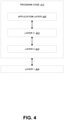
- FIG. 4 is a simplified block diagram of the program code 312 shown in FIG. 3 in accordance with one embodiment of the disclosed subject matter.
- the program code 312 includes an application layer 400, a Layer 3 portion 402, and a Layer 2 portion 404, and is coupled to a Layer 1 portion 406.
- the Layer 3 portion 402 may perform radio resource control.
- the Layer 2 portion 404 may perform link control.
- the Layer 1 portion 406 may perform and/or implement physical connections.
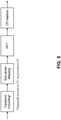
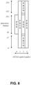
- FIG. 5 Figure 5 .1-1 of Section 5.1 of 3GPP TS 38.300 V15.8.0, entitled “Transmitter block diagram for CP-OFDM with optional DFT-spreading ", is reproduced herein as FIG. 5.
- the downlink transmission waveform is conventional OFDM using a cyclic prefix.
- the uplink transmission waveform is conventional OFDM using a cyclic prefix with a transform precoding function performing DFT spreading that can be disabled or enabled.
- FIG. 5.1-1 Transmitter block diagram for CP-OFDM with optional DFT-spreading
- Normal CP is supported for all sub-carrier spacings
- 12 consecutive sub-carriers form a Physical Resource Block (PRB).
- PRB Physical Resource Block
- Up to 275 PRBs are supported on a carrier.
- Table 5.1-1 Supported transmission numerologies.
- the UE may be configured with one or more bandwidth parts on a given component carrier, of which only one can be active at a time, as described in clauses 7.8 and 6.10 respectively.
- the active bandwidth part defines the UE's operating bandwidth within the cell's operating bandwidth. For initial access, and until the UE's configuration in a cell is received, initial bandwidth part detected from system information is used.
- Downlink and uplink transmissions are organized into frames with 10 ms duration, consisting of ten 1 ms subframes. Each frame is divided into two equally-sized half-frames of five subframes each.
- the slot duration is 14 symbols with Normal CP and 12 symbols with Extended CP, and scales in time as a function of the used sub-carrier spacing so that there is always an integer number of slots in a subframe.
- a closed loop Demodulation Reference Signal (DMRS) based spatial multiplexing is supported for Physical Downlink Shared Channel (PDSCH).
- PDSCH Physical Downlink Shared Channel
- Up to 8 and 12 orthogonal DL DMRS ports are supported for type 1 and type 2 DMRS respectively.
- Up to 8 orthogonal DL DMRS ports per UE are supported for SU-MIMO and up to 4 orthogonal DL DMRS ports per UE are supported for MU-MIMO.
- the number of SU-MIMO code words is one for 1-4 layer transmissions and two for 5-8 layer transmissions.
- the DMRS and corresponding PDSCH are transmitted using the same precoding matrix and the UE does not need to know the precoding matrix to demodulate the transmission.
- the transmitter may use different precoder matrix for different parts of the transmission bandwidth, resulting in frequency selective precoding.
- the UE may also assume that the same precoding matrix is used across a set of Physical Resource Blocks (PRBs) denoted Precoding Resource Block Group (PRG).
- PRBs Physical Resource Blocks
- PRG Precoding Resource Block Group
- the downlink physical-layer processing of transport channels consists of the following steps:
- the UE may assume that at least one symbol with demodulation reference signal is present on each layer in which PDSCH is transmitted to a UE, and up to 3 additional DMRS can be configured by higher layers.
- Phase Tracking RS may be transmitted on additional symbols to aid receiver phase tracking.
- the DL-SCH physical layer model is described in TS 38.202 [20].
- the Physical Downlink Control Channel can be used to schedule DL transmissions on PDSCH and UL transmissions on PUSCH, where the Downlink Control Information (DCI) on PDCCH includes:
- PDCCH can be used to for
- a UE monitors a set of PDCCH candidates in the configured monitoring occasions in one or more configured COntrol REsource SETs (CORESETs) according to the corresponding search space configurations.
- CORESETs COntrol REsource SETs
- a CORESET consists of a set of PRBs with a time duration of 1 to 3 OFDM symbols.
- the resource units Resource Element Groups (REGs) and Control Channel Elements (CCEs) are defined within a CORESET with each CCE consisting a set of REGs.
- Control channels are formed by aggregation of CCE. Different code rates for the control channels are realized by aggregating different number of CCE. Interleaved and non-interleaved CCE-to-REG mapping are supported in a CORESET.
- Polar coding is used for PDCCH.
- Each resource element group carrying PDCCH carries its own DMRS.
- QPSK modulation is used for PDCCH.
- the Synchronization Signal and PBCH block consists of primary and secondary synchronization signals (PSS, SSS), each occupying 1 symbol and 127 subcarriers, and PBCH spanning across 3 OFDM symbols and 240 subcarriers, but on one symbol leaving an unused part in the middle for SSS as show in Figure 5 .2.4-1.
- PSS, SSS primary and secondary synchronization signals
- PBCH PBCH spanning across 3 OFDM symbols and 240 subcarriers, but on one symbol leaving an unused part in the middle for SSS as show in Figure 5 .2.4-1.
- the possible time locations of SSBs within a half-frame are determined by sub-carrier spacing and the periodicity of the half-frames where SSBs are transmitted is configured by the network.
- different SSBs may be transmitted in different spatial directions (i.e. using different beams, spanning the coverage area of a cell).
- multiple SSBs can be transmitted.
- the PCIs of SSBs transmitted in different frequency locations do not have to be unique, i.e. different SSBs in the frequency domain can have different PCIs.
- the SSB corresponds to an individual cell, which has a unique NCGI (see clause 8.2).
- Such an SSB is referred to as a Cell-Defining SSB (CD-SSB).
- CD-SSB Cell-Defining SSB
- a PCell is always associated to a CD-SSB located on the synchronization raster.
- Polar coding is used for PBCH.
- the UE may assume a band-specific sub-carrier spacing for the SSB unless a network has configured the UE to assume a different sub-carrier spacing.
- PBCH symbols carry its own frequency-multiplexed DMRS.
- QPSK modulation is used for PBCH.
- the PBCH physical layer model is described in TS 38.202 [20].
- Link adaptation (AMC: adaptive modulation and coding) with various modulation schemes and channel coding rates is applied to the PDSCH.
- the same coding and modulation is applied to all groups of resource blocks belonging to the same L2 PDU scheduled to one user within one transmission duration and within a MIMO codeword.
- the UE may be configured to measure CSI-RS and estimate the downlink channel state based on the CSI-RS measurements.
- the UE feeds the estimated channel state back to the gNB to be used in link adaptation.
- Downlink power control can be used.
- Cell search is the procedure by which a UE acquires time and frequency synchronization with a cell and detects the Cell ID of that cell.
- NR cell search is based on the primary and secondary synchronization signals, and PBCH DMRS, located on the synchronization raster.
- the gNB provides the UE with the HARQ-ACK feedback timing either dynamically in the DCI or semi-statically in an RRC configuration.
- the UE may be configured to receive code block group based transmissions where retransmissions may be scheduled to carry a sub-set of all the code blocks of a TB.
- CA Carrier Aggregation
- CCs Component Carriers
- a UE may simultaneously receive or transmit on one or multiple CCs depending on its capabilities:
- CA is supported for both contiguous and non-contiguous CCs.
- the maximum number of configured CCs for a UE is 16 for DL and 16 for UL.
- TRPs transmission and reception points
- TCI indication framework shall be enhanced in Rel-16 at least for eMBB:
- the total number of CWs in scheduled PDSCHs, each of which is scheduled by one PDCCH, is up to 2.
- RRC configuration can be used to link multiple PDCCH/PDSCH pairs with multiple TRPs
- the maximum number of transmission layers per TRP is up to 2
- the maximum number of CORESETs that can be configured with the same TRP is up to UE capability, including at least a candidate value of 3.
- TCI code point When 2 TCI states are indicated by a TCI code point, at least for DMRS type 1 and type 2 for eMBB, if indicated DMRS ports are from two CDM groups,
- indicated DMRS ports are from one CDM group.
- the candidate values of higher layer parameter HigherLayerIndexPerCORESET are [0:1:M],
- each PUCCH resource may be associated with a value of higher layer index per CORESET
- the first TCI state corresponds to the CDM group of the first antenna port indicated by the antenna port indication table.
- the number of bits of TCI field in DCI is 3 if higher layer parameter tci-PresentInDCI is enabled.
- the maximum number of activated TCI states in mTRP operation is 8.
- the number of bits of TCI field in DCI is 3 if higher layer parameter tci-PresentInDCI is enabled.
- the total number of simultaneously activated TCI states is up to 8.
- the number of transmission occasions is indicated by following:
- RV sequence candidates For single-DCI based M-TRP URLLC scheme 2b, support following RV sequence candidates:
- the frequency density of the PTRS is determined by the number of PRBs associated to each TCI state
- URLLC schemes 2a/2b/3 can be differentiated by the following:
- RAN1 Answer1 The maximum total number of configured CORESETs per cell (across BWPs) is 16 Question 2. Does RAN1 think the current operation is sufficient for mPDCCH mTRP operation? RAN1 Answer 2: RAN1 would like to support 8 activated TCI states per TRP, i.e. per CORESETPoolIndex. The total number of activated TCI states that a UE supports is subject to UE capability. Further detailed design is up to RAN2.
- RAN1 would like to confirm that the understanding in RAN2 agreements is correct
- the support of this feature is part of UE capability.
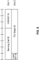
- FIG. 7 Figure 6 .1.3.15-1 of Section 6.1.3.15 of 3GPP TS 38.321 V15.8.0, entitled “TCI State Indication for UE-specific PDCCH MAC CE ", is reproduced herein as FIG. 8 .
- the network may activate and deactivate the configured TCI states for PDSCH of a Serving Cell by sending the TCI States Activation/Deactivation for UE-specific PDSCH MAC CE described in clause 6.1.3.14.
- the configured TCI states for PDSCH are initially deactivated upon configuration and after a handover.
- the MAC entity shall: 1> if the MAC entity receives a TCI States Activation/Deactivation for UE-specific PDSCH MAC CE on a Serving Cell: 2> indicate to lower layers the information regarding the TCI States Activation/Deactivation for UE-specific PDSCH MAC CE.
- the network may indicate a TCI state for PDCCH reception for a CORESET of a Serving Cell by sending the TCI State Indication for UE-specific PDCCH MAC CE described in clause 6.1.3.15.
- the MAC entity shall: 1> if the MAC entity receives a TCI State Indication for UE-specific PDCCH MAC CE on a Serving Cell: 2> indicate to lower layers the information regarding the TCI State Indication for UE-specific PDCCH MAC CE.
- the TCI States Activation/Deactivation for UE-specific PDSCH MAC CE is identified by a MAC subheader with LCID as specified in Table 6.2.1-1. It has a variable size consisting of following fields:
- the TCI State Indication for UE-specific PDCCH MAC CE is identified by a MAC subheader with LCID as specified in Table 6.2.1-1. It has a fixed size of 16 bits with following fields:
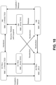
- FIG. 9 Figure 4 .2.1-2 of Section 4.2.1 of 3GPP TS 38.331 V15.8.0, entitled “UE state machine and state transitions between NR/5GC, E-UTRA/EPC and E-UTRA/5GC ", is reproduced herein as FIG. 10 .
- a UE is either in RRC_CONNECTED state or in RRC_INACTIVE state when an RRC connection has been established. If this is not the case, i.e. no RRC connection is established, the UE is in RRC_IDLE state.
- the RRC states can further be characterised as follows:
- Figure 4 .2.1-1 illustrates an overview of UE RRC state machine and state transitions in NR.
- a UE has only one RRC state in NR at one time.
- Figure 4 .2.1-2 illustrates an overview of UE state machine and state transitions in NR as well as the mobility procedures supported between NR/5GC E-UTRA/EPC and E-UTRA/5GC.
- Figure 4.2.1-2 UE state machine and state transitions between NR/5GC, E-UTRA/EPC and E-UTRA/5GC
- the IE ControlResourceSet is used to configure a time/frequency control resource set (CORESET) in which to search for downlink control information (see TS 38.213 [13], clause 10.1).
- ControlResourceSet field descriptions controlResourceSetId Value 0 identifies the common CORESET configured in MIB and in ServingCellConfigCommon ( controlResourceSetZero ) and is hence not used here in the ControlResourceSet IE. Values 1.. maxNrofControlResourceSets-1 identify CORESETs configured by dedicated signalling or in SIB1. The controlResourceSetId is unique among the BWPs of a serving cell.
- tci-PresentInDCI This field indicates if TCI field is present or absent in DL-related DCI. When the field is absent the UE considers the TCI to be absent/disabled.
- tci-StatesPDCCH-ToAddList A subset of the TCI states defined in pdsch-Config included in the BWP-DownlinkDedicated corresponding to the serving cell and to the DL BWP to which the ControlResourceSet belong to. They are used for providing QCL relationships between the DL RS(s) in one RS Set (TCI-State) and the PDCCH DMRS ports (see TS 38.213 [13], clause 6.).
- the network configures at most maxNrofTCI-StatesPDCCH entries.
- the IE BWP-DownlinkDedicated is used to configure the dedicated (UE specific) parameters of a downlink BWP.
- the ControlResourceSetId IE concerns a short identity, used to identify a control resource set within a serving cell.
- the ControlResourceSetId 0 identifies the ControlResourceSet#0 configured via PBCH ( MIB ) and in controlResourceSetZero ( ServingCellConfigCommon ).
- the ID space is used across the BWPs of a Serving Cell.
- the number of CORESETs per BWP is limited to 3 (including common and UE-specific CORESETs).
- the PDSCH-Config IE is used to configure the UE specific PDSCH parameters.
- PDSCH-Config field descriptions pdsch-AggregationFactor Number of repetitions for data (see TS 38.214 [19], clause 5.1.2.1).
- the UE applies the value 1.
- pdsch - TimeDomainAllocationList List of time-domain configurations for timing of DL assignment to DL data see table 5.1.2.1.1-1 in TS 38.214 [19]).
- resourceAllocation Configuration of resource allocation type 0 and resource allocation type 1 for non-fallback DCI see TS 38.214 [19], clause 5.1.2.2).
- TCI Transmission Configuration Indicator
- the IE TCI-State associates one or two DL reference signals with a corresponding quasi-colocation (QCL) type.
- QCL quasi-colocation
- the DL BWP which the RS is located in. cell The UE's serving cell in which the referenceSignal is configured. If the field is absent, it applies to the serving cell in which the TCI-State is configured.
- the RS can be located on a serving cell other than the serving cell in which the TCI-State is configured only if the qcl-Type is configured as typeC or typeD. See TS 38.214 [19] clause 5.1.5. referenceSignal Reference signal with which quasi-collocation information is provided as specified in TS 38.214 [19] subclause 5.1.5. qcl-Type QCL type as specified in TS 38.214 [19] subclause 5.1.5.
- the IE TCI-StateId is used to identify one TCI-State configuration.
- the IE PDCCH-Config is used to configure UE specific PDCCH parameters such as control resource sets (CORESET), search spaces and additional parameters for acquiring the PDCCH. If this IE is used for the scheduled cell in case of cross carrier scheduling, the fields other than searchSpacesToAddModList and searchSpacesToReleaseList are absent.
- PDCCH-Config field descriptions controlResourceSetToAddModList List of UE specifically configured Control Resource Sets (CORESETs) to be used by the UE.
- the network configures at most 3 CORESETs per BWP per cell (including UE-specific and common CORESETs). In case network reconfigures control resource set with the same ControlResourceSetId as used for commonControlResourceSet configured via PDCCH-ConfigCommon, the configuration from PDCCH-Config always takes precedence and should not be updated by the UE based on servingCellConfigCommon.
- searchSpacesToAddModList List of UE specifically configured Search Spaces The network configures at most 10 Search Spaces per BWP per cell (including UE-specific and common Search Spaces).
- a bandwidth part is a subset of contiguous common resource blocks defined in subclause 4.4.4.3 for a given numerology ⁇ i in bandwidth part i on a given carrier.
- the starting position N BWP , i start , ⁇ and the number of resource blocks N BWP , i size , ⁇ in a bandwidth part shall fulfil N grid , x start , ⁇ ⁇ N BWP , i start , ⁇ ⁇ N grid , x start , ⁇ + N grid , x size , ⁇ and N grid , x start , ⁇ ⁇ N BWP , i start , ⁇ + N BWP , i size , ⁇ ⁇ N grid , x start , ⁇ + N grid , x size , ⁇ , respectively.
- Configuration of a bandwidth part is described in clause 12 of [5, TS 38.213].
- a UE can be configured with up to four bandwidth parts in the downlink with a single downlink bandwidth part being active at a given time.
- the UE is not expected to receive PDSCH, PDCCH, or CSI-RS (except for RRM) outside an active bandwidth part.
- a UE can be configured with up to four bandwidth parts in the uplink with a single uplink bandwidth part being active at a given time. If a UE is configured with a supplementary uplink, the UE can in addition be configured with up to four bandwidth parts in the supplementary uplink with a single supplementary uplink bandwidth part being active at a given time.
- the UE shall not transmit PUSCH or PUCCH outside an active bandwidth part. For an active cell, the UE shall not transmit SRS outside an active bandwidth part.
- the index ⁇ may be dropped from N BWP , i start , ⁇ , N BWP , i size , ⁇ , N grid , x start , ⁇ , and N grid , x size , ⁇ .
- a UE For each DL BWP configured to a UE in a serving cell, a UE can be provided by higher layer signalling with P ⁇ 3 CORESETs. For each CORESET, the UE is provided the following by ControlResourceSet:
- the UE assumes that a DM-RS antenna port for PDCCH receptions in the CORESET is quasi co-located with
- a CORESET other than a CORESET with index 0 if a UE is provided a single TCI state for a CORESET, or if the UE receives a MAC CE activation command for one of the provided TCI states for a CORESET, the UE assumes that the DM-RS antenna port associated with PDCCH receptions in the CORESET is quasi co-located with the one or more DL RS configured by the TCI state.
- the UE For a CORESET with index 0, the UE expects that QCL-TypeD of a CSI-RS in a TCI state indicated by a MAC CE activation command for the CORESET is provided by a SS/PBCH block
- the UE For each DL BWP configured to a UE in a serving cell, the UE is provided by higher layers with S ⁇ 10 search space sets where, for each search space set from the S search space sets, the UE is provided the following by SearchSpace:
- the carrier indicator field value corresponds to the value indicated by CrossCarrierSchedulingConfig.
- the UE For an active DL BWP of a serving cell on which a UE monitors PDCCH candidates in a USS, if the UE is not configured with a carrier indicator field, the UE monitors the PDCCH candidates without carrier indicator field. For an active DL BWP of a serving cell on which a UE monitors PDCCH candidates in a USS, if a UE is configured with a carrier indicator field, the UE monitors the PDCCH candidates with carrier indicator field.
- a UE does not expect to monitor PDCCH candidates on an active DL BWP of a secondary cell if the UE is configured to monitor PDCCH candidates with carrier indicator field corresponding to that secondary cell in another serving cell.
- the UE monitors PDCCH candidates at least for the same serving cell.
- DCI format 1_0 is used for the scheduling of PDSCH in one DL cell.
- the following information is transmitted by means of the DCI format 1_0 with CRC scrambled by C-RNTI or CS-RNTI or MCS-C-RNTI:
- the DCI format 1_0 is for random access procedure initiated by a PDCCH order, with all remaining fields set as follows:
- DCI format 1_1 is used for the scheduling of PDSCH in one cell.
- the following information is transmitted by means of the DCI format 1_1 with CRC scrambled by C-RNTI or CS-RNTI or MCS-C-RNTI:
- DCI formats 1_1 are monitored in multiple search spaces associated with multiple CORESETs in a BWP for scheduling the same serving cell, zeros shall be appended until the payload size of the DCI formats 1_1 monitored in the multiple search spaces equal to the maximum payload size of the DCI format 1_1 monitored in the multiple search spaces.
- the UE can be configured with a list of up to M TCI-State configurations within the higher layer parameter PDSCH-Config to decode PDSCH according to a detected PDCCH with DCI intended for the UE and the given serving cell, where M depends on the UE capability maxNumberConfiguredTCIstatesPerCC.
- Each TCI-State contains parameters for configuring a quasi co-location relationship between one or two downlink reference signals and the DM-RS ports of the PDSCH, the DM-RS port of PDCCH or the CSI-RS port(s) of a CSI-RS resource.
- the quasi co-location relationship is configured by the higher layer parameter qcl-Type1 for the first DL RS, and qcl-Type2 for the second DL RS (if configured).
- the QCL types shall not be the same, regardless of whether the references are to the same DL RS or different DL RSs.
- the quasi co-location types corresponding to each DL RS are given by the higher layer parameter qcl-Type in QCL-Info and may take one of the following values:
- the UE receives an activation command, as described in clause 6.1.3.14 of [10, TS 38.321], used to map up to 8 TCI states to the codepoints of the DCI field 'Transmission Configuration Indication' in one CC/DL BWP or in a set of CCs/DL BWPs, respectively.
- an activation command as described in clause 6.1.3.14 of [10, TS 38.321], used to map up to 8 TCI states to the codepoints of the DCI field 'Transmission Configuration Indication' in one CC/DL BWP or in a set of CCs/DL BWPs, respectively.
- the UE may receive an activation command, as described in clause 6.1.3.24 of [10, TS 38.321], the activation command is used to map up to 8 combinations of one or two TCI states to the codepoints of the DCI field 'Transmission Configuration Indication'.
- the UE is not expected to receive more than 8 TCI states in the activation command.
- the indicated mapping between TCI states and codepoints of the DCI field 'Transmission Configuration Indication' should be applied starting from the first slot that is after slot n + 3 N slot subframe , ⁇ where ⁇ is the SCS configuration for the PUCCH.
- tci-PresentInDCI is set to "enabled” or tci-PresentInDCI-ForFormat1_2 is configured for the CORESET scheduling the PDSCH, and the time offset between the reception of the DL DCI and the corresponding PDSCH is equal to or greater than timeDurationForQCL if applicable
- the UE may assume that the DM-RS ports of PDSCH of a serving cell are quasi co-located with the SS/PBCH block determined in the initial access procedure with respect to 'QCL-TypeA', and when applicable, also with respect to'QCL-TypeD'.
- a UE If a UE is configured with the higher layer parameter tci-PresentInDCI that is set as 'enabled' for the CORESET scheduling the PDSCH, the UE assumes that the TCI field is present in the DCI format 1_1 of the PDCCH transmitted on the CORESET. If a UE is configured with the higher layer parameter tci-PresentInDCI-ForFormat1_2 for the CORESET scheduling the PDSCH, the UE assumes that the TCI field with a DCI field size indicated by tci-PresentInDCI-ForFormat1 _ 2 is present in the DCI format 1_2 of the PDCCH transmitted on the CORESET.
- the UE assumes that the TCI state or the QCL assumption for the PDSCH is identical to the TCI state or QCL assumption whichever is applied for the CORESET used for the PDCCH transmission.
- the UE shall use the TCI-State according to the value of the 'Transmission Configuration Indication' field in the detected PDCCH with DCI for determining PDSCH antenna port quasi co-location.
- the UE may assume that the DM-RS ports of PDSCH of a serving cell are quasi co-located with the RS(s) in the TCI state with respect to the QCL type parameter(s) given by the indicated TCI state if the time offset between the reception of the DL DCI and the corresponding PDSCH is equal to or greater than a threshold timeDurationForQCL, where the threshold is based on reported UE capability [13, TS 38.306].
- the indicated TCI state should be based on the activated TCI states in the slot with the scheduled PDSCH.
- the indicated TCI state should be based on the activated TCI states in the first slot with the scheduled PDSCH, and UE shall expect the activated TCI states are the same across the slots with the scheduled PDSCH.
- the UE When the UE is configured with CORESET associated with a search space set for cross-carrier scheduling and the UE is not configured with [ enableDefaultBeamForCSS ], the UE expects tci-PresentInDCI is set as 'enabled' or tci-PresentInDCI-ForFormat1_2 is configured for the CORESET, and if one or more of the TCI states configured for the serving cell scheduled by the search space set contains 'QCL-TypeD', the UE expects the time offset between the reception of the detected PDCCH in the search space set and the corresponding PDSCH is larger than or equal to the threshold timeDurationForQCL.
- the UE may assume that the DM-RS ports of PDSCH of a serving cell are quasi co-located with the RS(s) with respect to the QCL parameter(s) used for PDCCH quasi co-location indication of the CORESET associated with a monitored search space with the lowest controlResourceSetId in the latest slot in which one or more CORESETs within the active BWP of the serving cell are monitored by the UE.
- the UE is expected to prioritize the reception of PDCCH associated with that CORESET.
- This also applies to the intra-band CA case (when PDSCH and the CORESET are in different component carriers). If none of configured TCI states for the serving cell of scheduled PDSCH contains 'QCL-TypeD', the UE shall obtain the other QCL assumptions from the indicated TCI states for its scheduled PDSCH irrespective of the time offset between the reception of the DL DCI and the corresponding PDSCH.
- a UE is configured with enableDefaultTCIStatePerCoresetPoolIndex and the UE is configured by higher layer parameter PDCCH-Config that contains two different values of CORESETPoolIndex in ControlResourceSet, for both cases, when tci-PresentInDCI is set to 'enabled' and tci-PresentInDCI is not configured in RRC connected mode, if the offset between the reception of the DL DCI and the corresponding PDSCH is less than the threshold timeDurationForQCL, the UE may assume that the DM-RS ports of PDSCH associated with a value of CORESETPoolIndex of a serving cell are quasi co-located with the RS(s) with respect to the QCL parameter(s) used for PDCCH quasi co-location indication of the CORESET associated with a monitored search space with the lowest controlResourceSetId among CORESETs, which are configured with the same value of CORESETPoolIndex as the PDCCH scheduling
- the UE may assume that the DM-RS ports of PDSCH or PDSCH transmission occasions of a serving cell are quasi co-located with the RS(s) with respect to the QCL parameter(s) associated with the TCI states corresponding to the lowest codepoint among the TCI codepoints containing two different TCI states.
- the mapping of the TCI states to PDSCH transmission occasions is determined according to clause 5.1.2.1 by replacing the indicated TCI states with the TCI states corresponding to the lowest codepoint among the TCI codepoints containing two different TCI states.
- a TCI-State indicates one of the following quasi co-location type(s):
- the UE For an aperiodic CSI-RS resource in a NZP-CSI-RS-ResourceSet configured with higher layer parameter trs-Info, the UE shall expect that a TCI-State indicates 'QCL-TypeA' with a periodic CSI-RS resource in a NZP-CSI-RS-ResourceSet configured with higher layer parameter trs-Info and, when applicable,'QCL-TypeD' with the same periodic CSI-RS resource.
- the UE shall expect that a TCI-State indicates one of the following quasi co-location type(s):
- the UE shall expect that a TCI-State indicates one of the following quasi co-location type(s):
- the UE shall expect that a TCI-State indicates one of the following quasi co-location type(s):
- the UE shall expect that a TCI-State indicates one of the following quasi co-location type(s):
- the Rel-15 NR includes a number of MIMO features that facilitate utilization of a large number of antenna elements at base station for both sub-6GHz and over-6GHz frequency bands.
- the Rel-16 NR enhances Rel-15 by introducing enhanced Type II codebook with DFT-based compression, support for multi-TRP transmission especially for eMBB and PDSCH, enhancements for multi-beam operation including reduction in latency and/or overhead for various reconfigurations (QCL-related, measurements), SCell beam failure recovery (BFR), and L1-SINR.
- low PAPR reference signals and features enabling uplink full-power transmission are also introduced.
- NR is in the process of commercialization
- various aspects that require further enhancements can be identified from real deployment scenarios.
- Such aspects include the following.
- MPE maximum permissible exposure
- channels other than PDSCH can benefit from multi-TRP transmission (as well as multi-panel reception) which also includes multi-TRP for inter-cell operations.
- SRS can and should be further enhanced at least for capacity and coverage.
- the work item aims to specify the further enhancements identified for NR MIMO.
- the detailed objectives are as follows:
- NR Rel-15 beamforming technology may be adopted to achieve high power penetration in high frequency band (e.g., above 6 GHz). Accordingly, a gNB and a UE may both use transmission beams and/or receiving beams to ensure reliability of high throughput data in the high frequency band. Choosing a suitable transmission beam and/or receiving beam has played an important role in NR Rel-15. Beam indication for various channels and reference signals are discussed and captured in specifications along with the development of NR
- a beam indication for receiving a downlink (DL) transmission may consider (e.g., may only consider) transmission from a single TRP and/or transmission using a panel within a time duration (e.g., a time duration of at least one of one or more slots such as one slot, one or more mini-slots such as one mini-slot, etc.), such as from the perspective of UE.
- a time duration e.g., a time duration of at least one of one or more slots such as one slot, one or more mini-slots such as one mini-slot, etc.
- a single downlink transmission may be performed using different beams from multiple TRPs and/or multiple panels (e.g., for transmission from multiple TRPs and/or multiple panels, it may be implied that a single downlink transmission may be performed using different beams from multiple TRPs and/or multiple panels).
- a UE may receive multiple downlink transmissions from multiple TRPs and/or multiple panels within a time duration (e.g., a time duration of at least one of one or more slots such as one slot, one or more mini-slots such as one mini-slot, etc.).
- one or more enhancements to ultra-reliable and low latency communications with consideration of multiple TRP scenario have been made.
- one or more Physical Downlink Shared Channel (PDSCH) repetition schemes may be used to improve reliability of receiving PDSCH.
- the one or more PDSCH repetition schemes may comprise at least one of a Spatial Division Multiplexing (SDM) repetition scheme, a Frequency Division Multiplexing (FDM) repetition scheme, a mini-slot-based repetition scheme (e.g., Time Division Multiplexing (TDM)), a slot based repetition scheme (e.g., TDM), etc.
- SDM Spatial Division Multiplexing
- FDM Frequency Division Multiplexing
- TDM Time Division Multiplexing
- TDM slot based repetition scheme
- PDSCH Physical Downlink Control Channel
- UE may determine (e.g., derive) a beam or reference signal as Quasi-Colocation (QCL) for receiving PDSCH (e.g., the UE may determine which beam or reference signal to use for receiving the PDSCH).
- QCL Quasi-Colocation
- a UE may determine (e.g., derive) which beam or reference signal to use based on a TCI state indicated by the TCI bit field.
- DCI Downlink Control Information
- TCI Transmission Configuration Indicator
- a UE may determine (e.g., derive) which beam or reference signal to use based on a TCI state for receiving and/or monitoring a CORESET comprising the DCI format.
- a threshold may be timeDurationForQCL.
- a UE may determine the beam for receiving the PDSCH based on a CORESET beam from one or more CORESETs in a latest (e.g., most recent) slot (e.g., the latest slot may be before receiving the PDSCH and/or may be earlier than receiving the PDCCH) and a CORESET (associated with the CORESET beam, for example) is not a scheduling CORESET.
- a CORESET beam from one or more CORESETs in a latest (e.g., most recent) slot (e.g., the latest slot may be before receiving the PDSCH and/or may be earlier than receiving the PDCCH) and a CORESET (associated with the CORESET beam, for example) is not a scheduling CORESET.
- a beam or reference signal for receiving the PDSCH may be based on an indication of a TCI state from a scheduling DCI, or beam or reference signal for receiving the CORESET comprising the scheduling DCI.
- scheduling CORESET may refer to a CORESET comprising a scheduling DCI for a scheduled PDSCH, such as a scheduling DCI that schedules the scheduled PDSCH.
- PDCCH Physical Uplink Control Channel
- PUSCH Physical Uplink Shared Channel
- a linkage e.g., one linkage
- the one or more other PDCCH repetitions may provide the same scheduling information (e.g., the same scheduling result) for PDSCH or PUSCH as the failed PDCCH reception.
- transmitting multiple (e.g., two) scheduling PDCCHs may have an impact on determining a reference signal or beam for receiving a scheduled PDSCH (e.g., the multiple scheduling PDCCHs may have an impact for a DCI format without TCI present and/or without a TCI bit field present).
- a DCI format (without TCI and/or a TCI bit field present, for example) may be used for delivering common control information and/or may be a fallback DCI (e.g., DCI format 1_0).
- DCI format 1_0 e.g., DCI format 1_0
- there may be multiple (e.g., two) scheduling CORESETs with different beams it may be difficult for a UE to determine which beam or reference signal to use for receiving scheduled PDSCH.
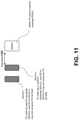
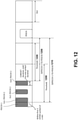
- FIG. 11 illustrates an exemplary scenario in which a UE is configured to receive PDCCH repetitions from a single TRP or a plurality of TRPs.
- Each PDCCH of PDCCH 1 and PDCCH 2 comprises a DCI format with or without a TCI bit field.
- PDCCH 1 (associated with CORESET i, for example) and PDCCH 2 (associated with CORESET j, for example, where j may be different than i) are separated by time domain.
- PDCCH 1 and PDCCH 2 may be in different symbols, where the different symbols may be in the same slot or in different slots.
- PDCCH 1 and PDCCH 2 may be in different slots (e.g., PDCCH 1 is in a first slot and PDCCH 2 is in a second slot different than the first slot).
- an interval e.g., a time domain interval, such as a distance and/or a duration
- the UE may determine two candidate beams, based on PDCCH 1 and PDCCH 2 or based on a corresponding CORESET (e.g., CORESET i and/or CORESET j), for receiving the scheduled PDSCH (e.g., the UE may derive the two candidate beams from PDCCH 1 and PDCCH 2 or from the corresponding CORESET).
- a first TCI state (e.g., TCI state (a)) may be used for receiving PDCCH 1 and/or a second TCI state (e.g., TCI state (b)) may be used for receiving PDCCH 2.
- the UE may be confused (and/or may not be able to determine) which beam or reference signal is to be used for receiving the scheduled PDSCH. Accordingly, the UE may consume more power by attempting to decode the scheduled PDSCH based on the two candidate beams (e.g., the two candidate beams derived from PDCCH 1 and PDCCH 2 and/or from the corresponding CORESET).
- an issue may occur if an interval between a PDCCH (e.g., PDCCH 1 and/or PDCCH 2) and the scheduled PDSCH is smaller than the threshold 1102.
- the threshold 1102 may be used for preparing a default beam for receiving the scheduled PDSCH (and/or the threshold 1102 may correspond to a duration of time in which the default beam for receiving the scheduled PDSCH may be prepared, for example).
- the threshold 1102 it is unclear which beam or reference signal is to be used for receiving the scheduled PDSCH.
- signal design for at least one of a bundle, a pair and/or an association for a plurality of scheduling PDCCHs for scheduling a PDSCH (e.g., one PDSCH) and/or additional PDSCHs may be considered.
- the following concepts and/or embodiments are provided which may be used for (but are not limited to being used for) determining a reference signal and/or beam for receiving a PDSCH (with consideration to improving the reliability of transmitting and/or receiving PDCCH, for example).
- any combination of above and/or below concepts can be jointly combined or formed to a new embodiment.
- the following embodiments can be used to solve (but are not limited to solving) one or more issues mentioned above (e.g., more power consumption by the UE due to attempting to decode the scheduled PDSCH based on the two candidate beams and/or the UE not being able to determine which beam and/or reference signal is to be used for receiving the scheduled PDSCH).
- a UE is configured and/or served in a serving cell.
- the UE may be configured with the serving cell and/or served in the serving cell by a network.
- the UE is configured with one or more Bandwidth Parts (BWPs).
- BWPs Bandwidth Parts
- the one or more BWPs may be indicated to the UE (e.g., the UE may receive an indication of the one or more BWPs).
- a BWP (e.g., an active BWP) may be activated (by the UE, for example).
- the BWP e.g., the active BWP
- the UE may receive an indication of the BWP.
- the UE may receive an indication (e.g., an instruction) to activate the BWP (e.g., the active BWP).
- the BWP (e.g., the active BWP) may be activated for the UE.
- an active downlink BWP may be activated (by the UE, for example).
- the active downlink BWP may be indicated to the UE (e.g., the UE may receive an indication of the active downlink BWP).
- the UE may receive an indication (e.g., an instruction) to activate the active downlink BWP.
- the active downlink BWP may be activated for the UE.
- an active uplink BWP may be activated (by the UE, for example).
- the active uplink BWP may be indicated to the UE (e.g., the UE may receive an indication of the active uplink BWP).
- the UE may receive an indication (e.g., an instruction) to activate the active uplink BWP.
- the active uplink BWP may be activated for the UE.
- the UE is configured with one or more BWPs.
- the one or more BWPs may be indicated to the UE (e.g., the UE may receive an indication of the one or more BWPs).
- the UE may be in RRC_CONNECTED state.
- the UE may be in RRC_INACTIVE state.
- the UE may be in RRC_IDLE state.
- the UE is served by a first TRP.
- the UE is served by a second TRP.
- the first TRP may belong to the serving cell and/or may be associated with the serving cell.
- the second TRP may belong to the serving cell and/or may be associated with the serving cell.
- the first TRP and the second TRP may belong to the same serving cell and/or may be associated with the same serving cell.
- the first TRP and the second TRP may belong to different serving cells and/or may be associated with different serving cells.
- the first TRP may belong to (and/or may be associated with) a first serving cell and the second TRP may belong to (and/or may be associated with) a second serving cell, wherein the first serving cell may be different than the second serving cell.
- the first TRP may schedule and/or transmit a downlink transmission or an uplink transmission for the UE.
- the first TRP may schedule a downlink transmission for the UE and/or transmit the downlink transmission to the UE.
- the first TRP may schedule an uplink transmission for the UE and/or receive the uplink transmission from the UE.
- the second TRP may schedule and/or transmit a downlink transmission or an uplink transmission for the UE.
- the second TRP may schedule a downlink transmission for the UE and/or transmit the downlink transmission to the UE.
- the second TRP may schedule an uplink transmission for the UE and/or receive the uplink transmission from the UE.
- the first TRP may receive an uplink transmission from the UE.
- the second TRP may receive an uplink transmission from the UE.
- the network may comprise a first network panel.
- the network may comprise a second network panel.
- the first network panel may be used to receive an uplink transmission from the UE.
- the second network panel may be used to receive an uplink transmission from the UE.
- a first CORESET e.g., one CORESET
- a first search space e.g., one search space
- a plurality of search spaces e.g., two search spaces
- a plurality of search spaces such as a plurality of search space sets (e.g., two search space sets) associated with CORESETs (e.g., corresponding CORESETs).
- the first CORESET (e.g., the one CORESET) may belong to the first TRP or the second TRP.
- the plurality of different CORESETs may belong to the first TRP and the second TRP, such as where a CORESET of the plurality of different CORESETs belongs to the first TRP and another CORESET of the plurality of different CORESETs belongs to the second TRP.
- the first search space e.g., the one search space
- the first search space is associated with a CORESET (e.g., one CORESET) belonging to the first TRP and a CORESET (e.g., one CORESET) belonging to the second TRP.
- the plurality of different CORESETs may belong to the same TRP (e.g., the first TRP or the second TRP).
- a search space (e.g., one search space) of the plurality of search spaces may be associated with a CORESET belonging to the first TRP and another search space of the plurality of search spaces (e.g., the two search spaces) may be associated with a CORESET belonging to the second TRP.
- a TCI code-point for indicating one or more reference signals for receiving and/or monitoring a CORESET, comprises one or more TCI states (e.g., one TCI state or two TCI states).
- each TCI state of the one or more TCI states is indicative of one or more reference signals (e.g., a QCL reference signal).
- the one or more TCI states are active (and/or activated) upon (and/or in response to and/or after) the UE receiving a Medium Access Control (MAC) Control Element (CE) for activating the one or more TCI states and/or the TCI code-point (e.g., the one TCI code-point).
- MAC Medium Access Control
- CE Medium Access Control Element
- a TCI code-point for indicating one or more reference signals for receiving and/or monitoring a scheduled PDSCH, comprises one or more TCI states (e.g., one TCI state or two TCI states).
- each TCI state of the one or more TCI states is indicative of one or more reference signals (e.g., a QCL reference signal).
- the one or more TCI states are active (and/or activated) upon (and/or in response to and/or after) the UE receiving a MAC CE for activating the one or more TCI states and/or the TCI code-point (e.g., the one TCI code-point).
- the UE may receive, from the network, one or more configurations and/or one or more parameters associated with URLLC (e.g., the one or more configurations and/or the one or more parameters may be for URLLC).
- one or more configurations and/or one or more parameters associated with URLLC e.g., the one or more configurations and/or the one or more parameters may be for URLLC.
- the UE may receive, from the network, a DCI and/or a MAC CE associated with URLLC (e.g., the DCI and/or the MAC CE may be for URLLC).
- a DCI and/or a MAC CE associated with URLLC e.g., the DCI and/or the MAC CE may be for URLLC.
- one or more identifiers may be known to the UE and/or the network.
- the UE may be configured with the one or more identifiers by the network (e.g., the UE may receive an identifier configuration associated with configuring the one or more identifiers).
- the network may indicate the one or more identifiers to the UE (e.g., the network may transmit an indication of the one or more identifiers to the UE).
- the UE may determine (e.g., derive) an identifier of the one or more identifiers (e.g., the UE may explicitly derive or implicitly derive the identifier).
- the UE may determine (e.g., derive) an identifier of the one or more identifiers based on a configuration other than the identifier configuration (e.g., the UE may explicitly derive or implicitly derive the identifier from the configuration).
- an identifier of the one or more identifiers may be an index and/or identity (ID) of a configuration and/or parameter (e.g., a higher layer configuration and/or parameter).
- ID an index and/or identity of a configuration and/or parameter (e.g., a higher layer configuration and/or parameter).
- an identifier of the one or more identifiers may be an index and/or identity of a configuration and/or parameter (e.g., the identifier may be at least one of a CORESET identity, a TCI state identity, an index and/or identity of a group of TCI states, an index and/or identity of a group of CORESETs, an index and/or identity of a PDCCH configuration, an index and/or identity of a PUCCH configuration, an index and/or identity of a PDSCH configuration, an index and/or identity of a PUSCH configuration, etc.).
- the identifier may be at least one of a CORESET identity, a TCI state identity, an index and/or identity of a group of TCI states, an index and/or identity of a group of CORESETs, an index and/or identity of a PDCCH configuration, an index and/or identity of a PUCCH configuration, an index and/or identity of a PDSCH configuration, an index and/or identity
- an identifier of the one or more identifiers may be associated with (e.g., related to) one or more parameters within a configuration (e.g., the identifier may be associated with (e.g., related to) at least one of a CORESET within a PDCCH configuration, a parameter within a CORESET, etc.).
- an identifier of the one or more identifiers may be indicated by a MAC CE and/or may be associated with (e.g., related to) a MAC CE signaling.
- an identifier of the one or more identifiers may be associated with (e.g., related to) one or more fields in a DCI.
- the identifier may be carried in (e.g., indicated by) the one or more fields in the DCI.
- the UE may receive (and/or may expect to receive) a plurality of PDCCHs and/or DCIs scheduling fully overlapped, partially overlapped or non-overlapping PDSCHs in time and frequency domain, wherein the UE is configured with two different values of a TRP identifier in the active BWP of the serving cell.
- the UE may receive (and/or may expect to receive) a plurality of PDCCHs and/or DCIs scheduling fully overlapped, partially overlapped or non-overlapping PDSCHs in time and frequency domain if (and/or when) the UE is configured with two different values of a TRP identifier in the active BWP of the serving cell.
- an identifier of the one or more identifiers may be a TRP-related index and/or identity (and/or the identifier may be a value of a TRP-related index and/or identity).
- an identifier of the one or more identifiers may be CORESETPoolIndex.
- the UE may determine (e.g., derive) one or more values of the identifier.
- a value of the identifier may be used to identify (e.g., differentiate and/or recognize) a TRP.
- the UE when a UE is scheduled with a downlink or uplink transmission (e.g., when the downlink or uplink transmission is scheduled for the UE), the UE may (and/or may be able to) identify (e.g., differentiate and/or recognize) the TRP scheduling the downlink or uplink transmission (e.g., the UE may identify the TRP scheduling the downlink or uplink transmission using an explicit or implicit method).
- identify e.g., differentiate and/or recognize
- the UE when a UE is scheduled with a downlink or uplink transmission (e.g., when the downlink or uplink transmission is scheduled for the UE), the UE may (and/or may be able to) identify (e.g., differentiate and/or recognize) the TRP scheduling the downlink or uplink transmission based on a value of the identifier (e.g., the UE may identify the TRP scheduling the downlink or uplink transmission based on the value of the identifier).
- identify e.g., differentiate and/or recognize
- the UE may (and/or may be able to) identify (e.g., differentiate and/or recognize) a TRP scheduling a downlink or uplink transmission based on a value of the identifier (e.g., the UE may identify the TRP scheduling the downlink or uplink transmission based on the value of the identifier).
- the UE may (and/or may be able to) identify (e.g., differentiate and/or recognize) a TRP scheduling a downlink or uplink transmission based on a value of the identifier (e.g., the UE may identify the TRP scheduling the downlink or uplink transmission based on the value of the identifier), wherein the identifier is associated with (and/or configured with) a scheduling CORESET for the downlink or uplink transmission (e.g., the scheduling CORESET may correspond to a CORESET comprising a scheduling DCI for a scheduled PDSCH, such as a scheduling DCI that schedules the scheduled PDSCH).
- the UE when the UE is scheduled with a downlink or uplink transmission (e.g., when the downlink or uplink transmission is scheduled for the UE), the UE may (and/or may be able to) identify (e.g., differentiate and/or recognize) the TRP scheduling the downlink or uplink transmission based on a value of the identifier (e.g., the UE may identify the TRP scheduling the downlink or uplink transmission based on the value of the identifier), wherein the value of the identifier is associated with (and/or configured with) the scheduling CORESET for the downlink or uplink transmission.
- identify e.g., differentiate and/or recognize
- the value of the identifier is associated with (and/or configured with) the scheduling CORESET for the downlink or uplink transmission.
- the UE may determine (e.g., derive) a first value of the identifier.
- the first value of the identifier may be indicated to the UE (e.g., the UE may receive an indication of the first value of the identifier).
- the UE may determine (e.g., derive) a second value of the identifier.
- the second value of the identifier may be indicated to the UE (e.g., the UE may receive an indication of the second value of the identifier).
- the first value of the identifier may be associated with (e.g., related to) the first TRP.
- the second value of the identifier may be associated with (e.g., related to) the second TRP.
- a first set of CORESETs (in the serving cell, for example) may be associated with the first TRP.
- a second set of CORESETs (in the serving cell, for example) may be associated with the second TRP.
- the first set of CORESETs (in the serving cell, for example) may be associated with (and/or configured with) the first value of the identifier.
- the second set of CORESETs (in the serving cell, for example) may be associated with (and/or configured with) the second value of the identifier.
- the UE may be configured and/or indicated (and/or instructed) to receive a downlink transmission via a plurality of spatial QCL assumptions.
- the UE may be configured and/or indicated (and/or instructed) via a high layer signaling indicating to the UE (e.g., instructing the UE) to operate in a transmission mode (e.g., the UE may be indicated and/or instructed to operate in the transmission mode via the high layer signaling).
- a high layer signaling indicating to the UE e.g., instructing the UE
- the UE may be indicated and/or instructed to operate in the transmission mode via the high layer signaling.
- the UE may be configured and/or indicated (and/or instructed) to receive one or more downlink transmissions via a plurality of panels.
- the UE may be configured and/or indicated (and/or instructed) via one or more high layer signalings indicating to the UE (e.g., instructing the UE) to operate in a transmission mode (e.g., the UE may be indicated and/or instructed to operate in the transmission mode via the one or more high layer signalings).
- the UE may be configured and/or indicated (and/or instructed) via one or more high layer signalings indicating to the UE (e.g., instructing the UE) to operate in a transmission mode (e.g., the UE may be indicated and/or instructed to operate in the transmission mode via the one or more high layer signalings), wherein when the UE operates in the transmission mode, the UE may receive one or more downlink transmissions via one or more beams.
- the UE may be configured and/or indicated (and/or instructed) via one or more high layer signalings indicating to the UE (e.g., instructing the UE) to operate in a transmission mode (e.g., the UE may be indicated and/or instructed to operate in the transmission mode via the one or more high layer signalings), wherein when the UE operates in the transmission mode, the UE may receive one or more downlink transmissions via one or more beams.
- the UE may be configured and/or indicated (and/or instructed) via one or more high layer signalings indicating to the UE (e.g., instructing the UE) to operate in a transmission mode (e.g., the UE may be indicated and/or instructed to operate in the transmission mode via the one or more high layer signalings), wherein when the UE operates in the transmission mode, the UE may receive one or more downlink transmissions via one or more panels.
- the UE may be configured and/or indicated (and/or instructed) via one or more high layer signalings indicating to the UE (e.g., instructing the UE) to operate in a transmission mode (e.g., the UE may be indicated and/or instructed to operate in the transmission mode via the one or more high layer signalings), wherein when the UE operates in the transmission mode, the UE may receive one or more downlink transmissions via one or more panels.
- the UE may be configured and/or indicated (and/or instructed) to receive one or more first downlink transmissions via a plurality of spatial QCL assumptions, and the UE may be configured and/or indicated (and/or instructed) to receive one or more second downlink transmissions via one spatial QCL assumption.
- the UE may receive (and/or may expect to receive) a downlink transmission via a plurality of spatial QCL assumptions.
- the UE may receive (and/or may expect to receive) one or more first downlink transmission via a plurality of spatial QCL assumptions, and may receive (and/or may expect to receive) one or more second downlink transmissions via one spatial QCL assumption.
- the UE may receive and/or be configured with a PDCCH configuration.
- the UE may receive and/or be configured with a PDCCH configuration, in the active downlink BWP, to receive and/or monitor PDCCH, search space and/or CORESET (e.g., the PDCCH configuration may be used by the UE to receive and/or monitor PDCCH, search space and/or CORESET).
- a PDCCH configuration in the active downlink BWP
- the PDCCH configuration may be used by the UE to receive and/or monitor PDCCH, search space and/or CORESET.
- the UE may receive and/or be configured with a first search space (e.g., a first search space configuration) in the active downlink BWP.
- a first search space e.g., a first search space configuration
- the UE may receive and/or be configured with a second search space (e.g., a second search space configuration) in the active downlink BWP.
- a second search space e.g., a second search space configuration
- the UE may monitor the first search space and/or the second search space in the active downlink BWP.
- the UE may be configured and/or indicated (and/or instructed) to monitor the first search space and/or the second search space in the active downlink BWP.
- the first search space may be associated with one CORESET, such as only one CORESET (e.g., the first CORESET).
- the first search space may be associated with a plurality of CORESETs (e.g., the first CORESET and the second CORESET).
- the second search space may be associated with one CORESET, such as only one CORESET (e.g., the second CORESET).
- the second search space may be associated with a plurality of CORESETs (e.g., the first CORESET and the second CORESET).
- a first CORESET is included in the first set of CORESETs.
- the first CORESET is included in the second set of CORESETs.
- a second CORESET is included in the second set of CORESETs.
- the first search space may be associated and/or configured with a first CORESET.
- the first search space may be associated and/or configured with a second CORESET and a first CORESET.
- the second search space may be associated and/or configured with a second CORESET.
- the first CORESET may be associated with the first TRP.
- the second CORESET may be associated with the second TRP.
- the first CORESET may be associated and/or configured with the first value of the identifier.
- the second CORESET may be associated and/or configured with the second value of the identifier.
- the first CORESET may be transmitted by the first TRP.
- the second CORESET may be transmitted by the second TRP.
- the UE may be configured with a first TCI state.
- the first TCI state may be indicated to the UE (e.g., the UE may receive an indication of the first TCI state).
- the UE may be configured with a second TCI state.
- the second TCI state may be indicated to the UE (e.g., the UE may receive an indication of the second TCI state).
- the UE may be configured with a first TCI state via a Radio Resource Control (RRC) signaling, a MAC CE and/or a DCI.
- RRC Radio Resource Control
- the first TCI state may be indicated to the UE via the RRC signaling, the MAC CE and/or the DCI (e.g., the RRC signaling, the MAC CE and/or the DCI may be indicative of the first TCI state).
- the UE may be configured with a second TCI state via a RRC signaling, a MAC CE and/or a DCI.
- the second TCI state may be indicated to the UE via the RRC signaling, the MAC CE and/or the DCI (e.g., the RRC signaling, the MAC CE and/or the DCI may be indicative of the second TCI state).
- the UE may be configured with a first TCI state to receive the first CORESET (e.g., the first TCI state may be used to receive the first CORESET).
- the first TCI state (for receiving the first CORESET, for example) may be indicated to the UE (e.g., the UE may receive an indication of the first TCI state).
- the UE may be configured with a second TCI state to receive the second CORESET (e.g., the second TCI state may be used to receive the second CORESET).
- the second TCI state (for receiving the second CORESET, for example) may be indicated to the UE (e.g., the UE may receive an indication of the second TCI state).
- the UE is configured with the first CORESET, wherein the first CORESET is configured with the first TCI state and the second TCI state.
- the first TCI state is active.
- the second TCI state is active.
- the first TCI state and the second TCI state are active (and/or activated) upon (and/or in response to and/or after) the UE receiving a MAC CE and/or RRC signaling for activation (of the first TCI state and the second TCI state).
- the first TCI state is active (and/or activated) upon (and/or in response to and/or after) the UE receiving a MAC CE and/or RRC signaling for activation (of the first TCI state).
- the second TCI state is active (and/or activated) upon (and/or in response to and/or after) the UE receiving a MAC CE and/or RRC signaling for activation (of the second TCI state).
- a plurality of CORESETs associated with (and/or configured in) the first search space are configured and/or associated with (e.g., must be configured and/or associated with) different values of the identifier, wherein the first search space is associated with (and/or configured) with the plurality of CORESETs.
- a first CORESET of the plurality of CORESETs may be associated with a first value of the identifier and a second CORESET of the plurality of CORESETs may be associated with a second value of the identifier different than the first value of the identifier.
- the plurality of CORESETs are configured and/or associated with (e.g., must be configured and/or associated with) different values of the identifier.
- the UE may monitor and/or receive a first DCI.
- the UE may monitor and/or receive a second DCI.
- the UE may monitor and/or receive a third DCI.
- the UE may monitor and/or receive a fourth DCI.
- the UE may monitor the second DCI after monitoring the first DCI.
- the UE may monitor the third DCI after monitoring the first DCI and/or monitoring the second DCI.
- the UE may monitor the fourth DCI after monitoring the first DCI, monitoring the second DCI and/or monitoring the third DCI.
- the second DCI, the third DCI and the fourth DCI may be initially monitoring the first DCI, followed by monitoring the second DCI, followed by monitoring the third DCI, followed by monitoring the fourth DCI.
- This example is an example of the monitoring order and does not mean and/or imply that the UE needs to and/or must monitor and/or detect all four DCIs.
- the UE may monitor one, some and/or all DCIs of the first DCI, the second DCI, the third DCI and the fourth DCI within a slot.
- the UE may monitor one, some and/or all DCIs of the first DCI, the second DCI, the third DCI and the fourth DCI across a plurality of slots.
- one, some and/or all DCIs of the first DCI, the second DCI, the third DCI and the fourth DCI may carry and/or indicate the same information (e.g., the same content).
- one, some and/or all DCIs of the first DCI, the second DCI, the third DCI and the fourth DCI may correspond to and/or be associated with the same PDCCH monitoring occasion of a search space (e.g., the first search space).
- one, some and/or all DCIs of the first DCI, the second DCI, the third DCI and the fourth DCI may be monitored and/or received in the same PDCCH monitoring occasion of a search space (e.g., the first search space).
- one, some and/or all DCIs of the first DCI, the second DCI, the third DCI and the fourth DCI may carry and/or indicate the same information (e.g., the same content), wherein the one, some and/or all DCIs of the first DCI, the second DCI, the third DCI and the fourth DCI are monitored and/or received by the UE in the same PDCCH monitoring occasion.
- the one, some and/or all DCIs of the first DCI, the second DCI, the third DCI and the fourth DCI may carry and/or indicate the same information (e.g., the same content).
- the UE may be configured with a third parameter.
- the third parameter may be indicated to the UE (e.g., the UE may receive an indication of the third parameter).
- the UE may determine (e.g., derive) the third parameter.
- the third parameter may be configured with and/or associated with a search space.
- the third parameter may be configured in a search space configuration for the search space.
- the UE may determine the third parameter based on the search space configuration for the search space (e.g., the UE may derive the third parameter from the search space configuration for the search space).
- the UE may determine a CORESET, that is associated and/or configured with the search space, to monitor and/or receive the first DCI, the second DCI, the third DCI and/or the fourth DCI (e.g., the UE may determine which CORESET, that is associated and/or configured with the search space, to monitor and/or receive the first DCI, the second DCI, the third DCI and/or the fourth DCI). For example, in response to determining the CORESET to monitor and/or receive the first DCI, the second DCI, the third DCI and/or the fourth DCI, the UE may monitor and/or receive, using the CORESET, the first DCI, the second DCI, the third DCI and/or the fourth DCI.
- the UE may, based on indicated content of the third parameter and/or based on existence and/or presence of the third parameter (in a field, for example), determine a CORESET, that is associated and/or configured with the search space, to monitor and/or receive the first DCI, the second DCI, the third DCI and/or the fourth DCI (e.g., the UE may determine which CORESET, that is associated and/or configured with the search space, to monitor and/or receive the first DCI, the second DCI, the third DCI and/or the fourth DCI).
- the UE may monitor and/or receive, using the CORESET, the first DCI, the second DCI, the third DCI and/or the fourth DCI.
- One example of determining and/or mapping one or more CORESETs to monitor and/or receive one or more DCIs may be determining and/or mapping the first CORESET for monitoring and/or receiving the first DCI and the second DCI, and determining and/or mapping the second CORESET for monitoring and/or receiving the third DCI and the fourth DCI.
- the example of determining and/or mapping one or more CORESETs to monitor and/or receive "the first DCI, the second DCI, the third DCI, the fourth DCI" may be "the first CORESET, the first CORESET, the second CORESET, the second CORESET".
- Another example of determining and/or mapping one or more CORESETs to monitor and/or receive one or more DCIs may be determining and/or mapping the first CORESET for monitoring and/or receiving the first DCI and the third DCI, and determining and/or mapping the second CORESET for monitoring and/or receiving the second DCI and the fourth DCI.
- the example of determining and/or mapping one or more CORESETs to monitor and/or receive "the first DCI, the second DCI, the third DCI, the fourth DCI" may be "the first CORESET, the second CORESET, the first CORESET, the second CORESET".
- the UE may determine a TCI state to monitor and/or receive the first DCI, the second DCI, the third DCI and/or the fourth DCI (e.g., the UE may determine which TCI state to monitor and/or receive the first DCI, the second DCI, the third DCI and/or the fourth DCI). For example, in response to determining the TCI state to monitor and/or receive the first DCI, the second DCI, the third DCI and/or the fourth DCI, the UE may monitor and/or receive, using the TCI state, the first DCI, the second DCI, the third DCI and/or the fourth DCI.
- the UE may, based on indicated content of the third parameter and/or based on existence and/or presence of the third parameter (in a field, for example), determine a TCI state to monitor and/or receive the first DCI, the second DCI, the third DCI and/or the fourth DCI (e.g., the UE may determine which TCI state to monitor and/or receive the first DCI, the second DCI, the third DCI and/or the fourth DCI).
- the UE may monitor and/or receive, using the TCI state, the first DCI, the second DCI, the third DCI and/or the fourth DCI.
- One example of determining and/or mapping one or more TCI states to monitor and/or receive one or more DCIs may be determining and/or mapping the first TCI state for monitoring and/or receiving the first DCI and the second DCI, and determining and/or mapping the second TCI state for monitoring and/or receiving the third DCI and the fourth DCI.
- the example of determining and/or mapping one or more TCI states to monitor and/or receive "the first DCI, the second DCI, the third DCI, the fourth DCI" may be "the first TCI state, the first TCI state, the second TCI state, the second TCI state".
- Another example of determining and/or mapping one or more TCI states to monitor and/or receive one or more DCIs may be determining and/or mapping the first TCI state for monitoring and/or receiving the first DCI and the third DCI, and determining and/or mapping the second TCI state for monitoring and/or receiving the second DCI and the fourth DCI.
- the example of determining and/or mapping one or more TCI states to monitor and/or receive "the first DCI, the second DCI, the third DCI, the fourth DCI" may be "the first TCI state, the second TCI state, the first TCI state, the second TCI state".
- a UE receives a first PDSCH (e.g., a first scheduled PDSCH) via a third TCI state (e.g., a third specific TCI state), wherein the first PDSCH (e.g., the first scheduled PDSCH) is scheduled by a plurality of PDCCHs.
- the UE receives the plurality of PDCCHs via a plurality of TCI states.
- the plurality of PDCCHs is used for indicating scheduled information (e.g., same scheduled information) to the UE.
- each PDCCH of one, some and/or all of the plurality of PDCCHs may indicate the same scheduled information.
- the plurality of PDCCHs is used to provide spatial and/or beam diversity to enhance receiving reliability of PDCCH.
- the plurality of PDCCHs may indicate a second PDSCH (e.g., a second scheduled PDSCH).
- the second PDSCH (e.g., the second scheduled PDSCH) may be after the first PDSCH (e.g., the first scheduled PDSCH).
- the first PDSCH may be in a first symbol and/or a first slot
- the second PDSCH may be in a second symbol and/or a second slot, wherein the second symbol and/or the second slot are after (and/or follow) the first symbol and/or the first slot.
- the UE may receive the second PDSCH (e.g., the second scheduled PDSCH) via a fourth TCI state (e.g., a fourth specific TCI state).
- the fourth TCI state may be the same as the third TCI state.
- the UE may receive a signal (e.g., a message) indicating bundling, pairing and/or association for the plurality of PDCCHs.
- a signal e.g., a message
- the UE may monitor and/or receive one or more PDCCHs and/or one or more DCIs within a slot, wherein the one or more PDCCHs and/or the one or more DCIs carry and/or indicate the same information (e.g., the same contents).
- the UE may be configured and/or indicated (and/or instructed) to monitor and/or receive one or more PDCCHs and/or one or more DCIs within a slot, wherein the one or more PDCCHs and/or the one or more DCIs carry and/or indicate the same information (e.g., the same contents).
- the plurality of PDCCHs comprises a first PDCCH carrying a first DCI.
- the plurality of PDCCHs comprises a second PDCCH carrying a second DCI.
- the plurality of TCI states comprises a first TCI state and a second TCI state.
- the first TCI state and the second TCI state are active.
- the plurality of PDCCHs occupy non-overlapped orthogonal frequency-division multiplexing (OFDM) symbols in time domain (e.g., OFDM symbols occupied by the plurality of PDCCHs do not overlap in time domain).
- OFDM orthogonal frequency-division multiplexing
- some and/or all PDCCHs of the plurality of PDCCHs belong to the same search space or to different search spaces.
- some and/or all PDCCHs of the plurality of PDCCHs belong to the same CORESET or to different CORESETs.
- the UE monitors PDCCHs of the plurality of PDCCHs on different monitoring occasions (e.g., the UE monitors one PDCCH of the plurality of PDCCHs on a first monitoring occasion and another PDCCH of the plurality of PDCCHs on a second monitoring occasion different than the first monitoring occasion).
- the UE monitors the first PDCCH (e.g., the first PDCCH candidate) on a first monitoring occasion.
- the first PDCCH e.g., the first PDCCH candidate
- the UE monitors the second PDCCH (e.g., the second PDCCH candidate) on a second monitoring occasion (different than the first monitoring occasion, for example).
- the second PDCCH e.g., the second PDCCH candidate
- the first monitoring occasion and the second monitoring occasion start in different OFDM symbols (e.g., the first monitoring occasion may start in a first OFDM symbol and the second monitoring occasion may start in a second OFDM symbol different than the first OFDM symbol).
- the UE is configured with a first CORESET.
- the first CORESET is associated with a plurality of active TCI states (e.g., two active TCI states, such as the first TCI state and the second TCI state).
- the first CORESET is not configured and/or enabled with tci-PresentInDCI (e.g., tci-PresentInDCI is not enabled for the first CORESET).
- the first CORESET is configured and/or enabled with tci-PresentInDCI (e.g., tci-PresentInDCI is enabled for the first CORESET).
- tci-PresentInDCI e.g., tci-PresentInDCI is enabled for the first CORESET.
- the first CORESET is associated with a first search space.
- the first CORESET is associated with a second search space.
- the UE is configured with a first search space for monitoring the first PDCCH.
- the UE is configured with the first search space for monitoring the second PDCCH.
- the UE is configured with a second search space for monitoring the second PDCCH.
- the first search space is associated with a first CORESET.
- the second search space is associated with a first CORESET.
- the first search space provides one or more first monitoring occasions (in a periodic manner, for example).
- the one or more first monitoring occasions may be periodic monitoring occasions and/or the one or more first monitoring occasions associated with the first search space may occur periodically (according to a periodicity, for example).
- the second search space provides one or more second monitoring occasions (in a periodic manner, for example).
- the one or more second monitoring occasions may be periodic monitoring occasions and/or the one or more second monitoring occasions associated with the second search space may occur periodically (according to a periodicity, for example).
- the first monitoring occasion is associated with the first TCI state.
- the UE monitors the one or more first monitoring occasions via the first TCI state.
- the second monitoring occasion is associated with the second TCI state.
- the UE monitors the one or more second monitoring occasions via the second TCI state.
- the UE receives the first PDCCH via the first TCI state.
- the UE receives the second PDCCH via the second TCI state.
- the first search space and the second search space are the same search space.
- the first search space and the second search space are different search spaces (e.g., the first search space is different than the second search space).
- a bit-map may indicative of starting OFDM symbols of monitoring occasions (e.g., the bit-map may be indicative of a first starting OFDM symbol of a first monitoring occasion, a second starting OFDM symbol of a second monitoring occasion, etc.).
- the first CORESET may have a CORESET duration of 2 OFDM symbols
- the bit-map (for the first search space, for example) may be (1,0,1,0,0,0,0,0,0,0,0,0,0,0,0), wherein the most left bit (e.g., a starting bit of the bit-map) corresponds to a first OFDM symbol of a slot (e.g., sequentially the first OFDM symbol of the slot, such as a starting OFDM symbol of the slot) and the most right bit (e.g., a last bit of the bit-map) corresponds to a last OFDM symbol of the slot.
- the first monitoring occasion starts from the first OFDM symbol of the slot, and the second monitoring occasion starts from the third OFDM symbol of the slot.
- the bit-map is (1,0,1,0,0,0,1,0,1,0,0,0,0,0)
- the UE may be configured with one or more pairs (e.g., one or more pairs of monitoring occasions), wherein the one or more pairs may comprise one pair or two pairs.
- one first monitoring occasion may start from the first OFDM symbol of the slot, and another first monitoring occasion may start from the seventh OFDM symbol of the slot (e.g., sequentially the seventh OFDM symbol of the slot), and one second monitoring occasion may start from the third OFDM symbol of the slot (e.g., sequentially the third OFDM symbol of the slot), and another second monitoring occasion may start from the ninth OFDM symbol of the slot (e.g., sequentially the ninth OFDM symbol of the slot), wherein the one first monitoring occasion and the another first monitoring occasion may be monitoring occasions of the one or more first monitoring occasions and the one second monitoring occasion and the another second monitoring occasion may be monitoring occasions of the one or more second monitoring occasions.
- the UE may monitor the four monitoring occasions for the plurality of PDCCHs.
- the four monitoring occasions (and/or PDCCHs monitored and/or received via the four monitoring occasions) may provide the same scheduling result for PDSCH (e.g., a scheduled PDSCH may be scheduled with same frequency and/or time allocation in the four monitoring occasions and/or the PDCCHs monitored and/or received via the four monitoring occasions).
- the first pair of the two pairs may comprise one first monitoring occasion (starting from the first OFDM symbol of the slot, for example) and one second monitoring occasion (starting from the third OFDM symbol of the slot, for example), wherein the one first monitoring occasion and the one second monitoring occasion may be used to schedule a PDSCH (e.g., one PDSCH, such as the first scheduled PDSCH).
- a PDSCH e.g., one PDSCH, such as the first scheduled PDSCH.
- the second pair of the two pairs may comprise another first monitoring occasion (starting from the seventh OFDM symbol of the slot, for example) and another second monitoring occasion (starting from the ninth OFDM symbol of the slot, for example), wherein the another first monitoring occasion and the another second monitoring occasion may be used to schedule another PDSCH (e.g., the second scheduled PDSCH or a PDSCH with a different Transport Block (TB) and/or MAC Protocol Data Unit (MAC PDU) than the first scheduled PDSCH), wherein the one first monitoring occasion and the another first monitoring occasion may be monitoring occasions of the one or more first monitoring occasions and the one second monitoring occasion and the another second monitoring occasion may be monitoring occasions of the one or more second monitoring occasions.
- another PDSCH e.g., the second scheduled PDSCH or a PDSCH with a different Transport Block (TB) and/or MAC Protocol Data Unit (MAC PDU) than the first scheduled PDSCH
- the one first monitoring occasion and the another first monitoring occasion may be monitoring occasions of the one or more first monitoring occasions
- the one first monitoring occasion may start from the first OFDM symbol
- the another first monitoring occasion may start from the third OFDM symbol
- the one second monitoring occasion may start from the seventh OFDM symbol
- the another second monitoring occasion may start from the ninth OFDM symbol.
- the first search space provides monitoring occasions in one or more slots (e.g., two or more consecutive slots) in a periodic manner.
- the first search space may be configured with 4 slots for every 10 slots (e.g., a periodicity of 10 slots).
- the first slot (e.g., sequentially the first slot of the 4 slots) and the third slot (e.g., sequentially the third slot of the 4 slots) may be (and/or may comprise) two monitoring occasions of the one or more first monitoring occasions
- the second slot (e.g., sequentially the second slot of the 4 slots) and the fourth slot (e.g., sequentially the fourth slot of the 4 slots) may be (and/or may comprise) two monitoring occasions of the one or more second monitoring occasions.
- the first slot and the second slot may be (and/or may comprise) two monitoring occasions of the one or more first monitoring occasions
- the third slot and the fourth slot may be (and/or may comprise) two monitoring occasions of the one or more second monitoring occasions.
- the UE may be configured with one or more pairs (e.g., one or more pairs of monitoring occasions) comprising one pair or two pairs.
- a periodicity, a slot offset, a duration and/or a bit-map for indicating a starting OFDM symbol of a monitoring occasion is the same (e.g., restricted to be the same) for both the first search space and the second search space.
- a number of monitoring occasions for the first search space may be the same as a number of monitoring occasions for the second search space.
- a number of monitoring occasions for the first search space within a periodicity of the first search space may be the same as a number of monitoring occasions for the second search space within a periodicity of the second search space.
- the third TCI state (e.g., the third specific TCI state) and/or the fourth TCI state (e.g., the fourth specific TCI state) are for (e.g., dedicated for) a bundle, a pair and/or an association of the plurality of PDCCHs.
- the third TCI state (e.g., the third specific TCI state) and/or the fourth TCI state (e.g., the fourth specific TCI state) are for (e.g., dedicated for) a bundle, a pair and/or an association of the first search space, the first PDCCH, the first monitoring occasion (e.g., the one or more first monitoring occasions) and/or the first DCI and are for (e.g., dedicated for) a bundle, a pair and/or an association of the second search space, the second PDCCH, the second monitoring occasion (e.g., the one or more second monitoring occasions) and/or the second DCI.
- the third TCI state (e.g., the third specific TCI state) may be the same as or different than the first TCI state.
- the third TCI state (e.g., the third specific TCI state) may be the same as or different than the second TCI state.
- the fourth TCI state (e.g., the fourth specific TCI state) may be the same as or different than the first TCI state.
- the fourth TCI state (e.g., the fourth specific TCI state) may be the same as or different than as the second TCI state.
- the third TCI state (e.g., the third specific TCI state) may be determined based on (e.g., derived from) an earlier monitoring occasion (e.g., an earliest monitoring occasion) of a pair of monitoring occasions (e.g., a pair of monitoring occasions within a periodicity of the first search space and/or the second search space).
- an earlier monitoring occasion e.g., an earliest monitoring occasion
- a pair of monitoring occasions e.g., a pair of monitoring occasions within a periodicity of the first search space and/or the second search space.
- the third TCI state (e.g., the third specific TCI state) may be determined based on (e.g., derived from) an earlier PDCCH (e.g., an earliest PDCCH) of the plurality of PDCCHs.
- the third TCI state (e.g., the third specific TCI state) may be determined based on (e.g., derived from) a latter monitoring occasion (e.g., a last monitoring occasion) of a pair of monitoring occasions (e.g., a pair of monitoring occasions within a periodicity of the first search space and/or the second search space).
- a latter monitoring occasion e.g., a last monitoring occasion
- a pair of monitoring occasions e.g., a pair of monitoring occasions within a periodicity of the first search space and/or the second search space.
- the third TCI state (e.g., the third specific TCI state) may be determined based on (e.g., derived from) a latter PDCCH (e.g., a last PDCCH) of the plurality of PDCCHs.
- the third TCI state (e.g., the third specific TCI state) may be the first TCI state (e.g., a primary active TCI state of the first CORESET), the second TCI state (e.g., a secondary active TCI state of the first CORESET) or a different TCI state (e.g., an active and/or configured TCI state other than the first TCI state and the second TCI state).
- the first TCI state e.g., a primary active TCI state of the first CORESET
- the second TCI state e.g., a secondary active TCI state of the first CORESET
- a different TCI state e.g., an active and/or configured TCI state other than the first TCI state and the second TCI state.
- the primary active TCI state (e.g., the first TCI state) is used with and/or without a pair, a bundle and/or an association of the first search space, the first PDCCH, the first monitoring occasion and/or the first DCI and the second search space, the second PDCCH, the second monitoring occasion and/or the second DCI.
- the pair, the bundle and/or the association may correspond to (i) a pair, a bundle and/or an association of the first search space and the second search space, (ii) a pair, a bundle and/or an association of the first PDCCH and the second PDCCH, (iii) a pair, a bundle and/or an association of the first monitoring occasion and the second monitoring occasion and/or (iv) a pair, a bundle and/or an association of the first DCI and the second DCI.
- the secondary active TCI state (e.g., the second TCI state) is used for (e.g., used only for) a pair, a bundle and/or an association of the first search space, the first PDCCH, the first monitoring occasion and/or the first DCI and the second search space, the second PDCCH, the second monitoring occasion and/or the second DCI.
- the pair, the bundle and/or the association may correspond to (i) a pair, a bundle and/or an association of the first search space and the second search space, (ii) a pair, a bundle and/or an association of the first PDCCH and the second PDCCH, (iii) a pair, a bundle and/or an association of the first monitoring occasion and the second monitoring occasion and/or (iv) a pair, a bundle and/or an association of the first DCI and the second DCI.
- a UE may monitor the third search space based on the primary active TCI state of the first CORESET (e.g., the first TCI state).
- a first interval (e.g., a first time domain interval, such as a first distance and/or a first duration) is between a last OFDM symbol (e.g., an ending OFDM symbol) of the first monitoring occasion and a starting OFDM symbol of a scheduled PDSCH (e.g., the first scheduled PDSCH).
- a second interval (e.g., a second time domain interval, such as a second distance and/or a second duration) is between a last OFDM symbol (e.g., an ending OFDM symbol) of the second monitoring occasion and a starting OFDM symbol of a scheduled PDSCH (e.g., the first scheduled PDSCH).
- a reference monitoring occasion is a latter monitoring occasion (e.g., a last monitoring occasion) among the first monitoring occasion (e.g., the one or more first monitoring occasions) and the second monitoring occasion (e.g., the one or more second monitoring occasions).
- the UE receives a scheduled PDSCH (e.g., the first scheduled PDSCH) via the third TCI state (e.g., the third specific TCI state) and/or the UE receives a scheduled PDSCH (e.g., the second scheduled PDSCH) via the fourth TCI state (e.g., the fourth specific TCI state).
- a scheduled PDSCH e.g., the first scheduled PDSCH
- the third TCI state e.g., the third specific TCI state
- the UE receives a scheduled PDSCH (e.g., the second scheduled PDSCH) via the fourth TCI state (e.g., the fourth specific TCI state).
- the UE without (and/or before) pairing, bundling and/or association (and/or before the UE is indicated and/or configured with pairing, bundling and/or association) and/or without (and/or before) the UE receiving the signal (e.g., the message) indicating pairing, bundling and/or association, the UE receives the scheduled PDSCH, scheduled by the first DCI, via the first TCI state (if the first interval is larger than or equal to the threshold).
- the signal e.g., the message
- the UE receives the scheduled PDSCH, scheduled by the first DCI, via the first TCI state if the UE does not have pairing, bundling and/or association, if the UE does receive the signal (e.g., the message) indicating pairing, bundling and/or association before the scheduled PDSCH and/or if the first interval is larger than or equal to the threshold.
- the signal e.g., the message
- the UE receives the scheduled PDSCH, scheduled by the first DCI, via a TCI state associated with a CORESET with a lowest CORESET identity (CORESET ID) among CORESETs in a latest (e.g., most recent) slot, wherein the CORESETs may be used for scheduling PDSCH in an active downlink BWP on the serving cell (if the first interval is smaller than the threshold).
- CORESET ID CORESET identity
- the UE receives the scheduled PDSCH, scheduled by the first DCI, via a TCI state associated with a CORESET with a lowest CORESET identity among CORESETs in a latest (e.g., most recent) slot if the UE does not have pairing, bundling and/or association, if the UE does receive the signal (e.g., the message) indicating pairing, bundling and/or association before the scheduled PDSCH and/or if the first interval is larger than or equal to the threshold (wherein the CORESETs may be used for scheduling PDSCH in an active downlink BWP on the serving cell).
- the signal e.g., the message
- the UE is not expected (and/or does not expect) to be scheduled with a PDSCH such that an interval (e.g., a time domain interval, such as a distance and/or a duration) between PDCCH 1 and the PDSCH is larger than or equal to the threshold and another interval (e.g., a time domain interval, such as a distance and/or a duration) between PDCCH 2 and the PDSCH is smaller than the threshold.
- an interval e.g., a time domain interval, such as a distance and/or a duration
- another interval e.g., a time domain interval, such as a distance and/or a duration
- the UE may receive a scheduled PDSCH (e.g., the first scheduled PDSCH) based on the third TCI state (e.g., the third specific TCI state) and/or may receive a scheduled PDSCH (e.g., the second scheduled PDSCH) based on the fourth TCI state (e.g., the fourth specific TCI state).
- a scheduled PDSCH e.g., the first scheduled PDSCH
- the third TCI state e.g., the third specific TCI state
- the fourth TCI state e.g., the fourth specific TCI state
- the network ensures and/or guarantees that the UE has enough time for switching via using the third TCI state (e.g., the third specific TCI state) for receiving the first PDSCH (e.g., the first scheduled PDSCH) and using the fourth TCI state (e.g., the fourth specific TCI state) for receiving the second PDSCH (e.g., the second scheduled PDSCH).
- the network ensures and/or guarantees that the UE has enough time to switch from using the third TCI state for receiving the first PDSCH (e.g., the first scheduled PDSCH) to using the fourth TCI state for receiving the second PDSCH (e.g., the second scheduled PDSCH).
- the network schedules the UE such that the UE has enough time for switching via using the third TCI state (e.g., the third specific TCI state) for receiving the first PDSCH (e.g., the first scheduled PDSCH) and using the fourth TCI state (e.g., the fourth specific TCI state) for receiving the second PDSCH (e.g., the second scheduled PDSCH).
- the network schedules the UE such that the UE has enough time to switch from using the third TCI state for receiving the first PDSCH (e.g., the first scheduled PDSCH) to using the fourth TCI state for receiving the second PDSCH (e.g., the second scheduled PDSCH).
- the UE may receive the first PDSCH (e.g., the first scheduled PDSCH) based on the third TCI state (e.g., the third specific TCI state).
- the first PDSCH e.g., the first scheduled PDSCH
- the third TCI state e.g., the third specific TCI state
- a TCI state (e.g., the first TCI state) is a default TCI state used when an interval (e.g., a time domain interval, such as a distance and/or a duration) between a PDCCH (e.g., a scheduling PDCCH) and a PDSCH (e.g., a PDSCH scheduled by the PDCCH) is smaller than the threshold.
- an interval e.g., a time domain interval, such as a distance and/or a duration
- a last PDCCH (in time domain) of a bundle, a pair and/or an association of the plurality of PDCCHs may be used to determine (e.g., derive and/or calculate an interval (e.g., a time domain interval, such as a distance and/or a duration) between the plurality of PDCCHs and a scheduled PDSCH (scheduled by the plurality of PDCCHs, for example).
- an interval e.g., a time domain interval, such as a distance and/or a duration
- an earlier (e.g., earliest) PDCCH (in time domain) of a bundle, a pair and/or an association of the plurality of PDCCHs may be used to determine (e.g., derive and/or calculate an interval (e.g., a time domain interval, such as a distance and/or a duration) between the plurality of PDCCHs and a scheduled PDSCH (scheduled by the plurality of PDCCHs, for example).
- an interval e.g., a time domain interval, such as a distance and/or a duration
- a third interval (e.g., a third time domain interval, such as a third distance and/or a third duration) is between a last PDCCH (in time domain) or an earlier (e.g., earliest) PDCCH (in time domain) of a bundle, a pair and/or an association of the plurality of PDCCHs and a scheduled PDSCH (e.g., the first scheduled PDSCH).
- the threshold may be timeDurationForQCL.
- the signal (e.g., the message) may indicate bundling, pairing and/or association for one or more CORESETs, one or more PDCCH candidates, PDCCH candidates with one or more aggregation levels, one or more search spaces, one or more monitoring occasions (e.g., the one or more monitoring occasions may be configured from a same search space or may be configured from different search spaces), one or more Control Channel Element (CCE) positions and/or one or more slots (and/or one or more OFDM symbols).
- CCE Control Channel Element
- the signal may be transmitted via a DCI, a MAC CE and/or a RRC signaling.
- the UE may perform soft-combining for a bundle, pair and/or association (e.g., one bundle, pair and/or association), such as a bundle, pair and/or association indicated by the signal.
- a bundle, pair and/or association e.g., one bundle, pair and/or association
- the UE may consider bundling, pairing and/or association (e.g., bundling, pairing and/or association indicated by the signal).
- the UE receives the signal in slot n.
- the UE transmits a Hybrid Automatic Repeat Request (HARQ) feedback corresponding to the signal (e.g., the HARQ feedback may be indicative of reception, such as successful reception, of the signal).
- HARQ Hybrid Automatic Repeat Request
- the UE transmits the HARQ feedback in slot n+k1.
- k1 is indicated by a scheduling DCI for scheduling the signal.
- the UE considers and/or applies one or more configurations and/or information of the signal (and/or one or more configurations and/or information based on the signal) at (and/or after) a first slot (e.g., an initial slot) after slot n+k1+x.
- a first slot e.g., an initial slot
- the UE may consider and/or apply one or more configurations and/or information of the signal (and/or one or more configurations and/or information based on the signal) starting from the first slot (e.g., the initial slot) after slot n+k1+x (and/or starting from a slot after the first slot after slot n+k1+x).
- x corresponds to a delay for confirming and/or activating one or more indications of the signal.
- x may be 3 slots or 3ms.
- An example of the signal may be ⁇ SS1, SS3 ⁇ (e.g., search space 1 and search space 3) from a same serving cell or ⁇ SS1 ⁇ (e.g., search space 1) from a first serving cell and ⁇ SS1 ⁇ (e.g., search space 1) from a second serving cell.
- ⁇ SS1, SS3 ⁇ e.g., search space 1 and search space 3 are associated with a same CORESET.
- the first DCI may be DCI format 1_0, DCI format 1_1, or DCI format 1_2.
- FIG. 12 illustrates an example scenario associated with a PDSCH being scheduled by PDCCHs.
- an interval 1210 between PDCCH 1 and PDSCH (e.g., a scheduled PDSCH) is larger than a threshold 1208 and an interval 1206 between PDCCH 2 and the PDSCH is larger than the threshold 1208.
- PDCCH 2 and PDCCH 1 are both in the first three OFDM symbols of a slot (e.g., sequentially the first three OFDM symbols of the slot).
- PDCCH 2 is in one or more OFDM symbols other than the first three OFDM symbols of the slot.
- PDCCH 2 is in a slot different than a slot that PDCCH 1 is in.
- the UE receives the PDSCH via a third TCI state (e.g., a specific TCI state).
- PDCCH 1 and PDCCH 2 are in a CORESET.
- the CORESET is configured without TCI state in DCI.
- PDCCH 1 and PDCCH 2 may belong to a same search space. Alternatively and/or additionally, PDCCH 1 and PDCCH 2 may belong to different search spaces.
- PDCCH 1 and PDCCH 2 may be received in a same monitoring occasion or different monitoring occasions in time domain.
- a first part (e.g., a first half) of the CORESET is received via one TCI state (e.g., a primary active TCI state of the CORESET) and a second part of the CORESET other than the first part of the CORESET (e.g., a second half of the CORESET other than the first half of the CORESET) is received via another TCI state (e.g., secondary active TCI state of the CORESET).
- the UE may receive PDCCH 1 via a first TCI state and may receive PDCCH 2 via a second TCI state.
- PDCCH 1 and PDCCH 2 schedule the PDSCH (e.g., PDCCH 1 schedules the PDSCH and PDCCH 2 schedules the PDSCH).
- the UE receives the PDSCH via a third TCI state (e.g., a specific TCI state).
- the third TCI state may be a TCI state for receiving PDCCH 1 or for receiving PDCCH 2 (e.g., the third TCI state may be the first TCI state or the second TCI state).
- the third TCI state may be determined (e.g., derived) based on a TCI state for a bundle, a pair and/or an association of two PDCCHs (e.g., PDCCH 1 and PDCCH 2).
- the third TCI state may be determined (e.g., derived) based on a last PDCCH of the bundle, the pair and/or the association of two PDCCHs (e.g., the third TCI state may be determined based on PDCCH 2) or the third TCI state may be determined (e.g., derived) based on an earliest PDCCH of the bundle, the pair and/or the association of two PDCCHs (e.g., the third TCI state may be determined based on PDCCH 1).
- the third TCI state may be determined based on a TCI state for receiving a last PDCCH of the bundle, the pair and/or the association of two PDCCHs (e.g., the third TCI state may be determined based on the second TCI state for receiving PDCCH 2) or the third TCI state may be determined based on a TCI state for receiving an earliest PDCCH of the bundle, the pair and/or the association of two PDCCHs (e.g., the third TCI state may be determined based on the first TCI state for receiving PDCCH 1).
- the third TCI state may be the primary active TCI state of the CORESET or the secondary active TCI state of the CORESET.
- FIG. 13 illustrates an example scenario associated with a PDSCH being scheduled by PDCCHs.
- an interval 1310 between PDCCH 1 and PDSCH (e.g., a scheduled PDSCH) is larger than a threshold 1302 and an interval 1306 between PDCCH 2 and the PDSCH is smaller than the threshold 1302.
- the UE may receive PDCCH 1 via a first TCI state and may receive PDCCH 2 via a second TCI state.
- the UE receives the PDSCH based on a third TCI state (e.g., a specific TCI state).
- the third TCI state may be determined (e.g., derived) based on a TCI state for receiving a last PDCCH of a bundle, a pair and/or an association of two PDCCHs comprising the PDCCH 1 and PDCCH 2 (e.g., the third TCI state may be determined based on the second TCI state for receiving PDCCH 2) or the third TCI state may be determined based on a TCI state for receiving an earliest PDCCH of the bundle, the pair and/or the association of two PDCCHs (e.g., the third TCI state may be determined based on the first TCI state for receiving PDCCH 1).
- the third TCI state may be a primary active TCI state of the CORESET or a secondary active TCI state of the CORESET.
- the third TCI state is used for receiving the PDSCH scheduled by the bundle, the pair and/or the association of two PDCCHs comprising PDCCH 1 and PDCCH 2.
- the third TCI state may be a TCI state other than a TCI state (e.g., the first TCI state) for receiving PDCCH 1 and/or a TCI state (e.g., the second TCI state) for receiving PDCCH 2.
- the UE does not receive the PDSCH based on a TCI state (e.g., the first TCI state) for receiving PDCCH 1. For example, if an interval (e.g., one interval) of the interval 1306 and the interval 1310 is larger than or equal to the threshold 1302, the UE may receive the PDSCH based on a TCI state and/or other information, wherein the TCI state and/or the other information are different than a TCI state (e.g., the first TCI state) for receiving PDCCH 1.
- a TCI state e.g., the first TCI state
- the UE may consider and/or deem an interval (e.g., a time domain interval, such as a distance and/or a duration) for the bundle, the pair and/or the association of two PDCCHs and the PDSCH as an interval (e.g., a time domain interval, such as a distance and/or a duration) between a last PDCCH (or CORESET) of the bundle, the pair and/or the association of two PDCCHs (comprising PDCCH 1 and PDCCH 2) in time domain and the PDSCH.
- Determination of the third TCI state may be based on an example scenario of FIG. 14 (e.g., since an interval between a bundle, a pair and/or an association and a scheduled PDSCH is smaller than a threshold).
- FIG. 14 illustrates an example scenario associated with a PDSCH being scheduled by PDCCHs.
- an interval 1410 between PDCCH 1 and a first PDSCH e.g., a scheduled PDSCH, shown as "PDSCH" in FIG. 14
- an interval 1406 between PDCCH 2 and the first PDSCH are smaller than a threshold 1402.
- the UE is configured with three CORESETs in a latest (e.g., last) slot (e.g., a latest slot before the first PDSCH).
- the three CORESETs may comprise CORESETs 2-3 belonging to CORESET pool x, and CORESET 1 belonging to CORESET pool y. Different CORESET pools may belong to different TRPs.
- the UE may receive PDCCHs on CORESET 2 and/or CORESET 3 for scheduling a second PDSCH on a first active downlink BWP on a first serving cell.
- the first active downlink BWP may be the same as an active downlink BWP on which the first PDSCH is scheduled and/or the first serving cell may be the same as a serving cell on which the first PDSCH is scheduled.
- PDCCH 1 and PDCCH 2 may be delivered on a CORESET belonging to CORESET pool x.
- the UE may receive the first PDSCH, scheduled by PDCCH 1 and/or PDCCH 2, via a third TCI state (e.g., a specific TCI state).
- the third TCI state may be determined (e.g., derived) based on a CORESET with a lowest CORESET identity of a CORESET pool for scheduling the first active downlink BWP on the first serving cell in a latest slot.
- the UE may consider and/or determine (e.g., derive) the third TCI state to be a TCI state for receiving CORESET 2 (belonging to CORESET pool x), since, for example, CORESET 2 is with the lowest CORESET identity in CORESET pool x in the latest slot for scheduling PDSCH on the first active downlink BWP on the first serving cell.
- PDCCH 1 may be delivered on a CORESET that is different than CORESETs 1-3.
- PDCCH 2 may be delivered on a CORESET that is different than CORESETs 1 ⁇ 3.
- the UE may receive the first PDSCH, scheduled by PDCCH 1 and/or PDCCH 2, via a third TCI state (e.g., a specific TCI state).
- the third TCI state may be determined (e.g., derived) based on a CORESET with a lowest CORESET identity among the CORESET delivering PDCCH 1 and the CORESET delivering PDCCH 2.
- the UE may consider and/or determine (e.g., derive) the third TCI state to be a TCI state for receiving CORESET 2 for scheduling PDSCH on the first active downlink BWP on the first serving cell.
- the UE is configured with a first CORESET.
- the UE is configured with a second CORESET.
- the first CORESET is associated with an active state (e.g., one active state), such as the first TCI state.
- the second CORESET is associated with an active state (e.g., one active state), such as the first TCI state.
- the first CORESET is not configured and/or enabled with tci-PresentInDCI (e.g., tci-PresentInDCI is not enabled for the first CORESET).
- the first CORESET is configured and/or enabled with tci-PresentInDCI (e.g., tci-PresentInDCI is enabled for the first CORESET).
- tci-PresentInDCI e.g., tci-PresentInDCI is enabled for the first CORESET.
- the second CORESET is not configured and/or enabled with tci-PresentInDCI (e.g., tci-PresentInDCI is not enabled for the first CORESET).
- the second CORESET is configured and/or enabled with tci-PresentInDCI (e.g., tci-PresentInDCI is enabled for the first CORESET).
- the first CORESET is associated with a first search space.
- the first CORESET is associated with a second search space.
- the second CORESET is associated with a second search space.
- the UE is configured with a first search space for monitoring the first PDCCH.
- the UE is configured with a second search space for monitoring the second PDCCH.
- the first search space is associated with a first CORESET.
- the first search space is associated with a second CORESET.
- the second search space is associated with a second CORESET.
- the first search space provides one or more first monitoring occasions and one or more second monitoring occasions (in a periodic manner, for example).
- the one or more first monitoring occasions may be periodic monitoring occasions and/or the one or more first monitoring occasions may occur periodically (according to a periodicity, for example).
- the one or more second monitoring occasions may be periodic monitoring occasions and/or the one or more second monitoring occasions may occur periodically (according to a periodicity, for example).
- the one or more first monitoring occasions are associated with the first search space and the first CORESET.
- the one or more second monitoring occasions are associated with the first search space and the second CORESET.
- even slots and/or even monitoring occasions (with respect to slot number/index 0 (e.g., physical slot number/index 0) or subframe index 0 (e.g., physical subframe index 0)) of the first search space are associated with the first CORESET.
- slot number/index 0 e.g., physical slot number/index 0
- subframe index 0 e.g., physical subframe index 0
- odd slots and/or odd monitoring occasions (with respect to slot number/index 0 (e.g., physical slot number/index 0) or subframe index 0 (e.g., physical subframe index 0)) of the first search space are associated with the second CORESET.
- slot number/index 0 e.g., physical slot number/index 0
- subframe index 0 e.g., physical subframe index 0
- Monitoring occasions m0 ⁇ m7 are monitoring occasions associated with (e.g., configured to and/or belonging to) a first search space (SS) and/or a second search space (SS).
- Monitoring occasions m0 ⁇ m7 are monitoring occasions associated with (e.g., configured to and/or belonging to) a first CORESET and/or a second CORESET.
- UE monitors monitoring occasions m0 ⁇ m7 based on TCI states for the first CORESET or the second CORESET.
- TCI state 0 (denoted as ⁇ 0 ⁇ ) may be used for monitoring and/or receiving monitoring occasions belonging to and/or configured to the one or more first monitoring occasions and TCI state 1 (denoted as ⁇ 1 ⁇ ) may be used for monitoring and/or receiving monitoring occasions belonging to and/or configured to the one or more second monitoring occasions.
- a first TCI state pattern ⁇ 0,1,0,1,0,1,0,1 ⁇ and a second TCI state pattern ⁇ 0,0,1,1,0,0,1,1 ⁇ illustrate monitoring occasions m0 ⁇ m7 being associated with TCI state 0 or TCI state 1.
- a monitoring occasion corresponding to a most left ⁇ 0 ⁇ of a TCI state pattern is paired to a monitoring occasion corresponding to a most left ⁇ 1 ⁇ of the TCI state pattern
- a monitoring occasion corresponding to a second-most left ⁇ 0 ⁇ of the TCI state pattern is paired to a monitoring occasion corresponding to a second-most left ⁇ 1 ⁇ of the TCI state pattern, and so on.
- the most left ⁇ 0 ⁇ may refer to sequentially the first ⁇ 0 ⁇ in the TCI state pattern
- the most left ⁇ 1 ⁇ may refer to sequentially the first ⁇ 1 ⁇ in the TCI state pattern
- the second-most left ⁇ 0 ⁇ may refer to sequentially the second ⁇ 0 ⁇ in the TCI state pattern
- the second-most left ⁇ 1 ⁇ may refer to sequentially the second ⁇ 0 ⁇ in the TCI state pattern
- a pair, an association and/or a bundle of each two pairs of monitoring occasions may be ⁇ m0, m1 ⁇ ⁇ m2, m3 ⁇ ⁇ m4, m5 ⁇ ⁇ m6, m7 ⁇ .
- a pair, an association and/or a bundle of each two pairs of monitoring occasions may be ⁇ m0, m2 ⁇ ⁇ m1, m3 ⁇ ⁇ m4, m6 ⁇ ⁇ m5, m7 ⁇ .
- the first search space provides one or more first monitoring occasions (in a periodic manner, for example).
- the one or more first monitoring occasions may be periodic monitoring occasions and/or the one or more first monitoring occasions associated with the first search space may occur periodically (according to a periodicity, for example).
- the second search space provides one or more second monitoring occasions (in a periodic manner, for example).
- the one or more second monitoring occasions may be periodic monitoring occasions and/or the one or more second monitoring occasions associated with the second search space may occur periodically (according to a periodicity, for example).
- the one or more first monitoring occasions are associated with the first search space and the first CORESET.
- the one or more second monitoring occasions are associated with the first search space and the second CORESET.
- a pair, an association and/or a bundle of each two pairs may be unequal.
- monitoring occasions ⁇ m0, m1, m2 ⁇ are associated with (e.g., configured to and/or belonging to) the first search space (SS) and monitoring occasions ⁇ m3, m4 ⁇ are associated with (e.g., configured to and/or belonging to) the second search space (SS).
- a number of monitoring occasions in one pair, association and/or bundle may be 5 (e.g., monitoring occasions ⁇ m0 ⁇ m4 ⁇ ).
- the UE may monitor monitoring occasions m0 ⁇ m2 via a TCI state associated with the first CORESET, and the UE may monitor monitoring occasions m3 ⁇ m4 via a TCI state associated with the second CORESET.
- the first monitoring occasion is associated with the first TCI state.
- the UE monitors the one or more first monitoring occasions via the first TCI state.
- the second monitoring occasion is associated with the second TCI state.
- the UE monitors the one or more second monitoring occasions via the second TCI state.
- the UE receives the first PDCCH via the first TCI state.
- the UE receives the second PDCCH via the second TCI state.
- the first search space and the second search space are different.
- TCI state and/or the concept of TCI state may refer to and/or may be replaced with beam, receiving beam, spatial QCL assumption, spatial parameter and/or spatial filter.
- Various techniques, embodiments, methods and/or alternatives of the present disclosure may be performed independently and/or separately from one another. Alternatively and/or additionally, various techniques, embodiments, methods and/or alternatives of the present disclosure may be combined and/or implemented using a single system. Alternatively and/or additionally, various techniques, embodiments, methods and/or alternatives of the present disclosure may be implemented concurrently and/or simultaneously.
- FIG. 17 is a flow chart 1700 according to one exemplary embodiment from the perspective of a UE (e.g., a UE in a wireless communication system).
- the UE is configured to monitor, in a downlink BWP on a serving cell, a first DCI on a first monitoring occasion and a second DCI on a second monitoring occasion.
- the UE may receive a signal (e.g., a message) for configuring and/or associating the first DCI and the second DCI (e.g., the signal may be indicative of a configuration of the first DCI and the second DCI and/or the signal may be indicative of an association between the first DCI and the second DCI), wherein the signal indicates that the first DCI and the second DCI indicate and/or schedule a first PDSCH (e.g., one PDSCH) (e.g., the signal indicates that the first DCI and the second DCI indicate and/or schedule the first PDSCH with same time-frequency resource allocation).
- a signal e.g., a message
- step 1715 the UE monitors the first DCI via a first spatial QCL assumption indicated by a first TCI state.
- the UE monitors the second DCI via a second spatial QCL assumption indicated by a second TCI state.
- step 1725 the UE receives the first PDSCH (e.g., the one PDSCH) via a third spatial QCL assumption indicated by a third TCI state (e.g., a specific TCI state).
- the third TCI state is used for a plurality of DCIs and/or a plurality of monitoring occasions scheduling for the first PDSCH (e.g., the third TCI state is used for a plurality of DCIs and/or a plurality of monitoring occasions that are used to schedule the first PDSCH).
- the first CORESET is associated with one or more active TCI states.
- the one or more active TCI states may comprise the first TCI state.
- the first CORESET is associated with two active TCI states (e.g., the first TCI state and the second TCI state).
- the UE may determine (e.g., derive) the second TCI state and/or the UE may activate the second TCI state for receiving the first CORESET.
- the first monitoring occasion and the second monitoring occasion occupy non-overlapped OFDM symbols in time domain.
- one or more OFDM symbols occupied by the first monitoring occasion may not overlap with one or more OFDM symbols occupied by the second monitoring occasion.
- the first monitoring occasion is in a different slot than the second monitoring occasion.
- the first monitoring occasion is in the same slot as the second monitoring occasion.
- the first CORESET is not configured and/or enabled with tci-PresentInDCI (e.g., tci-PresentInDCI is not enabled for the first CORESET).
- the UE upon (and/or in response to and/or after) the UE receiving the signal, the UE considers, applies and/or determines (based on the signal, for example) an association, a bundle and/or a pairing between the first DCI and the second DCI.
- the UE upon (and/or in response to and/or after) the UE receiving the signal, the UE considers, applies and/or determines (based on the signal, for example) an association, a bundle and/or a pairing between the first monitoring occasion and the second monitoring occasion.
- the UE receives the first PDSCH based on the third TCI state regardless of whether or not the first DCI and/or the second DCI are successfully detected.
- the UE receives the first PDSCH based on the third TCI state regardless of whether or not a DCI (e.g., one DCI) of the first DCI and the second DCI is successfully detected.
- a DCI e.g., one DCI
- the UE receives the first PDSCH based on the third TCI state regardless of whether or not both of the first DCI and the second DCI are successfully detected.
- the UE receives the PDSCH based on the third TCI state (rather than receiving the PDSCH based on the first TCI state and/or the second TCI state).
- the UE upon (and/or in response to and/or after) the UE receiving a DCI on a monitoring occasion on the first CORESET, where the DCI and/or the monitoring occasion are without an association, without a bundle and/or without pairing, the UE receives a PDSCH scheduled by the DCI based on the first TCI state.
- the UE receives the PDSCH (e.g., the first PDSCH), scheduled by the first DCI, based on the first TCI state (e.g., an active TCI state of the first CORESET).
- the PDSCH e.g., the first PDSCH
- the first TCI state e.g., an active TCI state of the first CORESET
- a first interval (e.g., a time domain interval, such as a distance and/or a duration) between the first monitoring occasion and the first PDSCH is larger than or equal to a threshold.
- the first interval is in units of OFDM symbols (e.g., the interval is indicative of a number of OFDM symbols between the first monitoring occasion and the first PDSCH).
- the first interval corresponds to an interval between a last OFDM symbol of the first monitoring occasion and the first PDSCH (e.g., the first interval may be indicative of a number of OFDM symbols between the last OFDM symbol of the first monitoring occasion and the first PDSCH).
- a second interval (e.g., a time domain interval, such as a distance and/or a duration) between the second monitoring occasion and the first PDSCH is larger than or equal to the threshold.
- the second interval is in units of OFDM symbols (e.g., the second interval is indicative of a number of OFDM symbols between the second monitoring occasion and the first PDSCH).
- the second interval corresponds to an interval between a last OFDM symbol of the second monitoring occasion and the first PDSCH (e.g., the second interval may be indicative of a number of OFDM symbols between the last OFDM symbol of the second monitoring occasion and the first PDSCH).
- the first interval between the first monitoring occasion and the first PDSCH is smaller than the threshold.
- the second interval between the second monitoring occasion and the first PDSCH is smaller than the threshold.
- the threshold is used for determining whether or not to use a default beam of a default TCI state for receiving a scheduled PDSCH.
- the UE is not expected (and/or does not expect) that an interval of the first interval and the second interval is larger than the threshold and another interval of the first interval and the second interval is smaller than the threshold.
- the UE is not expected (and/or does not expect) that the first interval and the second interval are configured and/or indicated (with a configuration and/or an indication, for example) such that an interval of the first interval and the second interval is larger than the threshold and another interval of the first interval and the second interval is smaller than the threshold.
- the signal indicates the third TCI state.
- the third TCI state is the first TCI state or the second TCI state.
- the third TCI state is a TCI state other than the first TCI state and the second TCI state.
- the third TCI state is a primary TCI state of the first CORESET.
- the third TCI state is determined based on (e.g., derived from) a primary TCI state of the first CORESET.
- the first DCI and the second DCI are associated with a first CORESET.
- the UE is configured with a first set of CORESETs (in the serving cell, for example).
- the first set of CORESETs may be associated with a first TRP.
- the first set of CORESETs may comprise the first CORESET (and/or may comprise one or more other CORESETs in addition to the first CORESET).
- the UE is configured with a second set of CORESETs (in the serving cell, for example).
- the second set of CORESETs may be associated with a second TRP.
- the second set of CORESETs may comprise the second CORESET (and/or may comprise one or more other CORESETs in addition to the second CORESET).
- the first DCI is associated with a first CORESET.
- the second DCI is associated with a second CORESET.
- the first CORESET is associated with one or more active TCI states.
- the one or more active TCI states associated with the first CORESET may comprise the first TCI state.
- the second CORESET is associated with one or more active TCI states.
- the one or more active TCI states associated with the second CORESET may comprise the second TCI state.
- the first CORESET is associated with two active TCI states.
- the two active TCI states associated with the first CORESET may comprise the first TCI state and a fourth TCI state.
- the second CORESET is associated with two active TCI states.
- the two active TCI states associated with the second CORESET may comprise the first TCI state and a fifth TCI state.
- the fourth TCI state is the same as the fifth TCI state.
- the fourth TCI state and the fifth TCI state are used for indicating the third TCI state for a pairing, bundling and/or association between the first DCI and the second DCI.
- the fourth TCI state and the fifth TCI state are used for indicating the third TCI state for a pairing, bundling and/or association between the first monitoring occasion and the second monitoring occasion.
- the fourth TCI state and the fifth TCI state are used for indicating the third TCI state for a pairing, bundling and/or association between the first CORESET and the second CORESET.
- the first CORESET and the second CORESET are associated with different CORESET pool identities (e.g., CORESETPoolIndex ).
- the first CORESET may be associated with a first CORESET pool identity (e.g., a first CORESETPoolIndex ) and the second CORESET may be associated with a second CORESET pool identity (e.g., a second CORESETPoolIndex ) different than the first CORESET pool identity.
- the UE may determine (e.g., derive) the fourth TCI state or the fifth TCI state for the third TCI state. For example, the UE may determine that the third TCI state is the fourth TCI state or the fifth TCI state based on the signal, and/or the UE may use the third TCI state (e.g., the fourth TCI state or the fifth TCI state) to receive the first PDSCH.
- the third TCI state e.g., the fourth TCI state or the fifth TCI state
- the UE may activate the fourth TCI state or the fifth TCI state for the third TCI state.
- the UE may activate the fourth TCI state or the fifth TCI state based on the signal, and/or the UE may use the fourth TCI state or the fifth TCI state to receive the first PDSCH (e.g., the third TCI state used to receive the first PDSCH may be the fourth TCI state or the fifth TCI state).
- the first monitoring occasion and the second monitoring occasion occupy non-overlapped OFDM symbols in time domain.
- one or more OFDM symbols occupied by the first monitoring occasion may not overlap with one or more OFDM symbols occupied by the second monitoring occasion.
- the first monitoring occasion and the second monitoring occasion are associated with a search space configuration (e.g., one search space configuration).
- the first monitoring occasion is associated with a first search space configuration and/or a first search space and/or the second monitoring occasion is associated with a second search space configuration and/or a second search space.
- the first CORESET is not configured and/or enabled with tci-PresentInDCI (e.g., tci-PresentInDCI is not enabled for the first CORESET).
- the second CORESET is not configured and/or enabled with tci-PresentInDCI (e.g., tci-PresentInDCI is not enabled for the second CORESET).
- the UE upon (and/or in response to and/or after) the UE receiving the signal, the UE considers, applies and/or determines (based on the signal, for example) an association, a bundle and/or a pairing between the first DCI and the second DCI.
- the UE upon (and/or in response to and/or after) the UE receiving the signal, the UE considers, applies and/or determines (based on the signal, for example) an association, a bundle and/or a pairing between the first monitoring occasion and the second monitoring occasion.
- the UE upon (and/or in response to and/or after) the UE receiving the signal, the UE considers, applies and/or determines (based on the signal, for example) an association, a bundle and/or a pairing between the first CORESET and the second CORESET.
- the signal provides information related to (and/or indicative of) a bundle and/or pair of two PDCCHs, a bundle and/or pair of two CORESETs, a bundle and/or pair of two monitoring occasions of respective CORESET, and/or a bundle and/or pair of two search spaces.
- the UE receives the PDSCH (e.g., the first PDSCH), scheduled by the first DCI, based on the first TCI state (e.g., an active TCI state of the first CORESET).
- the PDSCH e.g., the first PDSCH
- the first TCI state e.g., an active TCI state of the first CORESET
- the UE receives the PDSCH (e.g., the first PDSCH), scheduled by the second DCI, based on the second TCI state (e.g., an active TCI state of the second CORESET).
- the PDSCH e.g., the first PDSCH
- the second TCI state e.g., an active TCI state of the second CORESET
- the UE receives the first PDSCH, scheduled by the second DCI and/or the first DCI, based on the third TCI state (e.g., the third TCI state may be the secondary active TCI state of the first CORESET or the secondary active TCI state of the second CORESET).
- the pairing, the bundling and/or the association may correspond to a pairing, a bundling and/or an association between the first DCI and the second DCI.
- the pairing, the bundling and/or the association may correspond to a pairing, a bundling and/or an association between the first monitoring occasion and the second monitoring occasion.
- the pairing, the bundling and/or the association may correspond to a pairing, a bundling and/or an association between the first CORESET and the second CORESET.
- the pairing, the bundling and/or the association may correspond to a pairing, a bundling and/or an association between a first search space and a second search space.
- the signal indicates the third TCI state.
- the signal indicates a CORESET among the paired, the bundled and/or the associated CORESETs (indicated by the signal, for example) for determining (e.g., deriving) the third TCI state.
- the paired, the bundled and/or the associated CORESETs may comprise the first CORESET and the second CORESET.
- the CORESET indicated by the signal may be used to determine (e.g., derive) the third TCI state.
- the signal indicates a DCI among the paired, the bundled and/or the associated DCIs (indicated by the signal, for example) for determining (e.g., deriving) the third TCI state.
- the paired, the bundled and/or the associated DCIs may comprise the first DCI and the second DCI.
- the DCI indicated by the signal may be used to determine (e.g., derive) the third TCI state.
- the signal indicates one or more criteria for determining the third TCI state.
- the third TCI state is the first TCI state or the second TCI state.
- the third TCI state is a TCI state other than the first TCI state and the second TCI state.
- the third TCI state is the fourth TCI state or the fifth TCI state.
- the third TCI state is the secondary active TCI state of the first CORESET or the secondary active TCI state of the second CORESET.
- the third TCI state is determined based on (e.g., derived from) the secondary active TCI state of the first CORESET or the secondary active TCI state of the second CORESET.
- the third TCI state is determined based on (e.g., derived from) an earlier (e.g., earliest) monitoring occasion of a pair, an association and/or a bundle of monitoring occasions comprising a first monitoring occasion (e.g., one first monitoring occasion) and a second monitoring occasion (e.g., one second monitoring occasion).
- the third TCI state may be determined based on (e.g., derived from) the first CORESET (e.g., the third TCI state may be based on the first TCI state and/or the third TCI state may be the first TCI state).
- the UE determines (e.g., derives) and/or considers the third TCI state based on the earlier (e.g., earliest) associated monitoring occasion (e.g., the first monitoring occasion), such as based on the first TCI state (e.g., the third TCI state may be the first TCI state).
- the latter e.g., last) monitoring occasion, of the pair, the association and/or the bundle of monitoring occasions, is after the earlier (e.g., earliest) monitoring occasion of the pair, the association and/or the bundle of monitoring occasions.
- the third TCI state is determined based on (e.g., derived from) a latter (e.g., last) monitoring occasion of a pair, an association and/or a bundle of monitoring occasions comprising a first monitoring occasion (e.g., one first monitoring occasion) and a second monitoring occasion (e.g., one second monitoring occasion).
- the third TCI state may be determined based on (e.g., derived from) the second CORESET (e.g., the third TCI state may be based on the second TCI state and/or the third TCI state may be the second TCI state).
- the UE receives and/or detects (e.g., if the UE only receives and/or detects) the first DCI on an earlier (e.g., earliest) monitoring occasion of the pair, the association and/or the bundle of monitoring occasions (e.g., if the UE only receives and/or detects the second DCI on the first monitoring occasion), the UE determines (e.g., derives) and/or considers the third TCI state based on the latter (e.g., last) associated monitoring occasion (e.g., the second monitoring occasion), such as based on the second TCI state (e.g., the third TCI state may be the second TCI state).
- the earlier (e.g., earliest) monitoring occasion, of the pair, the association and/or the bundle of monitoring occasions is before the latter (e.g., last) monitoring occasion of the pair, the association and/or the bundle of monitoring occasions.
- the third TCI state is determined based on (e.g., derived from) a CORESET with a lowest CORESET identity among the pair, the bundle and/or the association of CORESETs comprising the first CORESET and the second CORESET (e.g., the third TCI state is determined based on (e.g., derived from) a CORESET with a lowest CORESET identity among the first CORESET and the second CORESET).
- the third TCI state is determined based on (e.g., derived from) a CORESET with a highest CORESET identity among the pair, the bundle and/or the association of CORESETs comprising the first CORESET and the second CORESET (e.g., the third TCI state is determined based on (e.g., derived from) a CORESET with a highest CORESET identity among the first CORESET and the second CORESET).
- the third TCI state is determined based on (e.g., derived from) a best quality (e.g., a best channel quality) among: (i) a latest (e.g., most recent) Reference Signal Received Power (RSRP) report (e.g., Layer 1/Layer 3 (L1/L3) RSRP report), a latest (e.g., most recent) Channel State Information (CSI) report (e.g., L1/L3-CSI report), a latest (e.g., most recent) beam report (e.g., L1/L3-beam report) and/or a latest (e.g., most recent) Reference Signal (RS) report (e.g., L1/L3-RS report) for the first CORESET and/or the first TCI state, and (ii) a latest (e.g., most recent) RSRP report (e.g., L1/L3-RSRP report), a latest (e.g., most recent) CSI report (e.g.,
- the third TCI state is determined based on (e.g., derived from), such as always determined based on (e.g., always derived from), a third CORESET (e.g., a specific CORESET).
- the third CORESET may be a CORESET on a latest (e.g., most recent) slot in which the UE monitors the first set of CORESETs for scheduling a PDSCH within the active downlink BWP on the serving cell, wherein the third CORESET has a lowest CORESET identity (ID) among CORESETs on the latest (e.g., most recent) slot.
- ID CORESET identity
- the third CORESET may be a CORESET on a latest (e.g., most recent) slot where the UE monitors the first set of CORESETs for scheduling a PDSCH within the active downlink BWP on the serving cell.
- the third CORESET may be a CORESET with the lowest CORESET identity among CORESETs on the latest slot.
- the first set of CORESETs is associated with a lowest CORESET pool identity (among CORESET pool identities with which the UE is configured, for example.
- the first set of CORESETs is associated with a highest CORESET pool identity (among CORESET pool identities with which the UE is configured, for example.
- the UE determines (e.g., derives) and/or considers the third TCI state based on a best quality (e.g., a best channel quality) among: (i) a latest (e.g., most recent) RSRP report (e.g., L1/L3-RSRP report), a latest (e.g., most recent) CSI report (e.g., L1/L3-CSI report), a latest (e.g., most recent) beam report (e.g., L1/L3-beam report) and/or a latest (e.g., most recent) RS report (e.g., L1/L3-RS report) for the first CORESET and/or the first TCI state, and/or (ii) a latest (e.g., a latest (e.g., a latest (e.g., most recent) RSRP report (e.g., L1/L3-RS report) for the first CORESET and/or the first TCI state,
- the UE determines (e.g., derives) and/or considers the third TCI state based on a best quality (e.g., a best channel quality) among: (i) a latest (e.g., most recent) RSRP report (e.g., L1/L3-RSRP report), a latest (e.g., most recent) CSI report (e.g., L1/L3-CSI report), a latest (e.g., most recent) beam report (e.g., L1/L3-beam report) and/or a latest (e.g., most recent) RS report (e.g., a latest (e.g., most recent) RS report (e.g., L1/L3-RSRP report), a latest (e.g., most recent) beam report (e.g., L1/L3-beam report) and/or a latest (e.g., most recent) RS report (e.g., a latest (e.g., most
- spatial QCL assumption corresponds to (and/or means and/or implies) a beam that is used by the UE to receive (e.g., receive at least one of a signal, a channel, information, an indication, etc.).
- the device 300 includes a program code 312 stored in the memory 310.
- the CPU 308 may execute program code 312 to enable the UE (i) to be configured to monitor, in a downlink BWP on a serving cell, a first DCI on a first monitoring occasion and a second DCI on a second monitoring occasion, (ii) to receive a signal (e.g., a message) for configuring and/or associating the first DCI and the second DCI (e.g., the signal may be indicative of a configuration of the first DCI and the second DCI and/or the signal may be indicative of an association between the first DCI and the second DCI), wherein the signal indicates that the first DCI and the second DCI indicate and/or schedule a first PDSCH (e.g., one PDSCH) (e.g., the signal indicates that the first DCI and the
- FIG. 18 is a flow chart 1800 according to one exemplary embodiment from the perspective of a UE (e.g., a UE in a wireless communication system).
- the UE monitors a first PDCCH, via a first spatial QCL assumption associated with a first TCI state, on a first monitoring occasion of a first CORESET.
- the UE monitors a second PDCCH, via a second spatial QCL assumption associated with a second TCI state, on a second monitoring occasion of a second CORESET.
- the UE determines an interval (e.g., a time domain interval, such as a distance and/or a duration, in units of at least one of slots, symbols, time, etc.) between a last OFDM symbol of a reference monitoring occasion and a starting (e.g., initial) OFDM symbol of a scheduled PDSCH, wherein the reference monitoring occasion is a last (and/or latter) monitoring occasion (in time domain) of the first monitoring occasion (of the first CORESET) and the second monitoring occasion (of the second CORESET).
- the reference monitoring occasion may be the first monitoring occasion if the first monitoring occasion is after the second monitoring occasion.
- the reference monitoring occasion may be the second monitoring occasion if the second monitoring occasion is after the first monitoring occasion.
- the UE receives the scheduled PDSCH via a third spatial QCL assumption associated with a third TCI state (e.g., a specific TCI state), wherein the third TCI state is determined based on a lowest CORESET identity (ID) of a first CORESET identity of the first CORESET and a second CORESET identity of the second CORESET.
- a third TCI state e.g., a specific TCI state
- the third spatial QCL assumption associated with the third TCI state (that is determined based on the lowest CORESET identity of the first CORESET identity and the second CORESET identity) may be used to receive the scheduled PDSCH if the interval is larger than or equal to the threshold.
- the third TCI state is determined based on a CORESET associated with the lowest CORESET identity.
- the third TCI state may be determined based on the first CORESET if the first CORESET identity is lower than the second CORESET identity.
- the third TCI state may be determined based on the second CORESET if the second CORESET identity is lower than the first CORESET identity.
- the scheduled PDSCH is scheduled by the first PDCCH and the second PDCCH.
- the threshold is associated with (e.g., used for) determining whether or not to use a default beam of a default TCI state for reception of a PDSCH.
- the threshold is timeDurationForQCL.
- the first TCI state is activated for receiving the first CORESET and the first PDCCH does not comprise a TCI field
- the first CORESET is not configured (and/or enabled) with tci-PresentInDCI
- tci-PresentInDCI is not enabled for the first CORESET
- the second TCI state is activated for receiving the second CORESET and the second PDCCH does not comprise a TCI field
- the second CORESET is not configured (and/or enabled) with tci-PresentInDCI
- tci-PresentInDCI is not enabled for the second CORESET.
- the third TCI state is the first TCI state or the second TCI state.
- the third TCI state is the first TCI state if the first CORESET identity of the first CORESET is lower than the second CORESET identity of the second CORESET.
- the third TCI state is the second TCI state if the second CORESET identity is lower than the first CORESET identity of the first CORESET.
- the UE receives a signal (e.g., a message) indicative of a first search space, comprising the first PDCCH, and indicative of a second search space comprising the second PDCCH.
- the signal may be for configuring and/or associating the first search space and the second search space.
- the first PDCCH and the second PDCCH are associated with scheduling the scheduled PDSCH (and/or the first PDCCH and the second PDCCH are associated with scheduling same information, such as same time-frequency resource allocation information, for the scheduled PDSCH).
- the association of the first search space and the second search space may correspond to an association between the first search space and the second search space.
- the association of the first search space and the second search space may correspond to an association between the first search space and the scheduled PDSCH and/or an association between the second search space and the scheduled PDSCH.
- the first monitoring occasion (of the first CORESET) and the second monitoring occasion (of the second CORESET) are in a first slot (e.g., slot n).
- the UE monitors one or more PDCCHs, associated with one or more CORESETs, in a second slot (e.g., slot m), wherein the second slot is different than the first slot and the second slot is a most recent (e.g., latest) slot in which the UE monitors PDCCH before receiving the scheduled PDSCH.
- a second slot e.g., slot m
- the second slot is different than the first slot and the second slot is a most recent (e.g., latest) slot in which the UE monitors PDCCH before receiving the scheduled PDSCH.
- the one or more CORESETs comprise a third CORESET with a lowest CORESET identity among one or more CORESET identities of the one or more CORESETs.
- the one or more CORESETs comprise one or more second CORESETs other than the first CORESET and the second CORESET.
- the first monitoring occasion of the first CORESET is in a downlink BWP on a serving cell
- the second monitoring occasion of the second CORESET is in the downlink BWP on the serving cell.
- the UE is configured with a first search space and a second search space in the downlink BWP.
- the first monitoring occasion of the first CORESET is associated with the first search space.
- the second monitoring occasion of the second CORESET is associated with the second search space.
- the device 300 includes a program code 312 stored in the memory 310.
- the CPU 308 may execute program code 312 to enable the UE (i) to monitor a first PDCCH, via a first spatial QCL assumption associated with a first TCI state, on a first monitoring occasion of a first CORESET, (ii) to monitor a second PDCCH, via a second spatial QCL assumption associated with a second TCI state, on a second monitoring occasion of a second CORESET, (iii) to determine an interval between a last OFDM symbol of a reference monitoring occasion and a starting OFDM symbol of a scheduled PDSCH, wherein the reference monitoring occasion is a last monitoring occasion of the first monitoring occasion and the second monitoring occasion, and (iv) based on the interval being larger than or equal to a threshold, to receive the scheduled PDSCH via a third spatial QCL assumption associated with
- FIG. 19 is a flow chart 1900 according to one exemplary embodiment from the perspective of a UE (e.g., a UE in a wireless communication system).
- the UE monitors a first CORESET, via a first spatial QCL assumption associated with a first TCI state, on a first monitoring occasion, wherein a first PDCCH is associated with the first CORESET.
- the UE monitors a second CORESET, via a second spatial QCL assumption associated with a second TCI state, on a second monitoring occasion, wherein a second PDCCH is associated with the second CORESET.
- the first PDCCH schedules a PDSCH and the second PDCCH schedules the PDSCH (e.g., both the first PDCCH and the second PDCCH schedule the PDSCH).
- the first PDCCH schedules one or more transmissions (other than the PDSCH) in addition to scheduling the PDSCH.
- the second PDCCH schedules one or more transmissions (other than the PDSCH) in addition to scheduling the PDSCH.
- the UE determines an interval (e.g., a time domain interval, such as a distance and/or a duration, in units of at least one of slots, symbols, time, etc.) between a last OFDM symbol of a reference monitoring occasion and a starting (e.g., initial) OFDM symbol of the PDSCH, wherein the reference monitoring occasion is a last (and/or latter) monitoring occasion (in time domain) of the first monitoring occasion and the second monitoring occasion.
- the reference monitoring occasion may be the first monitoring occasion if the first monitoring occasion is after the second monitoring occasion.
- the reference monitoring occasion may be the second monitoring occasion if the second monitoring occasion is after the first monitoring occasion.
- the UE receives the PDSCH via a third spatial QCL assumption associated with a third TCI state (e.g., a specific TCI state), wherein the third TCI state is determined based on a lowest CORESET identity (ID) of a first CORESET identity of the first CORESET and a second CORESET identity of the second CORESET.
- the third spatial QCL assumption associated with the third TCI state may be used to receive the PDSCH if the interval is larger than or equal to the threshold.
- the third TCI state is determined based on a CORESET associated with the lowest CORESET identity.
- the third TCI state may be determined based on the first CORESET if the first CORESET identity is lower than the second CORESET identity.
- the third TCI state may be determined based on the second CORESET if the second CORESET identity is lower than the first CORESET identity.
- the first TCI state is activated for receiving the first CORESET and the first PDCCH does not comprise a TCI field
- the first CORESET is not configured (and/or enabled) with tci-PresentInDCI
- tci-PresentInDCI is not enabled for the first CORESET
- the second TCI state is activated for receiving the second CORESET and the second PDCCH does not comprise a TCI field
- the second CORESET is not configured (and/or enabled) with tci-PresentInDCI
- tci-PresentInDCI is not enabled for the second CORESET.
- the third TCI state is the first TCI state or the second TCI state.
- the third TCI state is the first TCI state if the first CORESET identity of the first CORESET is lower than the second CORESET identity of the second CORESET.
- the third TCI state is the second TCI state if the second CORESET identity is lower than the first CORESET identity of the first CORESET.
- the first monitoring occasion and the second monitoring occasion are in a first slot (e.g., slot n).
- the UE monitors one or more PDCCHs, associated with one or more CORESETs, in a second slot (e.g., slot m), wherein the second slot is different than the first slot and the second slot is a most recent (e.g., latest) slot in which the UE monitors PDCCH before receiving the PDSCH.
- a second slot e.g., slot m
- the second slot is different than the first slot and the second slot is a most recent (e.g., latest) slot in which the UE monitors PDCCH before receiving the PDSCH.
- the one or more CORESETs comprise a third CORESET with a lowest CORESET identity among one or more CORESET identities of the one or more CORESETs.
- the one or more CORESETs comprise one or more second CORESETs other than the first CORESET and the second CORESET.
- the first monitoring occasion is in a downlink BWP on a serving cell
- the second monitoring occasion is in the downlink BWP on the serving cell.
- the UE is configured with a first search space and a second search space in the downlink BWP.
- the first monitoring occasion is associated with the first search space.
- the second monitoring occasion is associated with the second search space.
- the device 300 includes a program code 312 stored in the memory 310.
- the CPU 308 may execute program code 312 to enable the UE (i) to monitor a first CORESET, via a first spatial QCL assumption associated with a first TCI state, on a first monitoring occasion, wherein a first PDCCH is associated with the first CORESET, (ii) to monitor a second CORESET, via a second spatial QCL assumption associated with a second TCI state, on a second monitoring occasion, wherein a second PDCCH is associated with the second CORESET, the first PDCCH schedules a PDSCH (e.g., one PDSCH) and the second PDCCH schedules the PDSCH (e.g., both the first PDCCH and the second PDCCH schedule the one PDSCH), (iii) to determine an interval between a last OFDM symbol of
- FIG. 20 is a flow chart 2000 according to one exemplary embodiment from the perspective of a UE (e.g., a UE in a wireless communication system).
- the UE monitors a first PDCCH, via a first spatial QCL assumption associated with a first TCI state, on a first monitoring occasion of a first CORESET.
- the UE monitors a second PDCCH, via a second spatial QCL assumption associated with a second TCI state, on a second monitoring occasion of a second CORESET.
- the UE determines an interval (e.g., a time domain interval, such as a distance and/or a duration, in units of at least one of slots, symbols, time, etc.) between a last OFDM symbol of a reference monitoring occasion and a starting (e.g., initial) OFDM symbol of a scheduled PDSCH, wherein the reference monitoring occasion is a last (and/or latter) monitoring occasion (in time domain) of the first monitoring occasion (of the first CORESET) and the second monitoring occasion (of the second CORESET), and wherein the UE does not expect to be scheduled with the scheduled PDSCH such that (and/or the UE does not expect that the scheduled PDSCH is scheduled such that) the interval is smaller than a threshold.
- a time domain interval such as a distance and/or a duration, in units of at least one of slots, symbols, time, etc.
- the UE may not expect the scheduled PDSCH to be scheduled at a time at which the interval would be smaller than the threshold (and/or the scheduled PDSCH may not be scheduled at a time at which the interval would be smaller than the threshold).
- the reference monitoring occasion may be the first monitoring occasion if the first monitoring occasion is after the second monitoring occasion.
- the reference monitoring occasion may be the second monitoring occasion if the second monitoring occasion is after the first monitoring occasion.
- the scheduled PDSCH is scheduled by the first PDCCH and the second PDCCH.
- the UE may not expect that the first PDCCH and the second PDCCH schedule the scheduled PDSCH such that the interval is smaller than the threshold.
- the UE may not expect the first PDCCH and the second PDCCH to schedule the scheduled PDSCH at a time at which the interval would be smaller than the threshold (and/or the first PDCCH and the second PDCCH may not schedule the scheduled PDSCH at a time at which the interval would be smaller than the threshold).
- the threshold is associated with (e.g., used for) determining whether or not to use a default beam of a default TCI state for reception of a PDSCH.
- the threshold is timeDurationForQCL.
- the first TCI state is activated for receiving the first CORESET and the first PDCCH does not comprise a TCI field
- the first CORESET is not configured (and/or enabled) with tci-PresentInDCI
- tci-PresentInDCI is not enabled for the first CORESET
- the second TCI state is activated for receiving the second CORESET and the second PDCCH does not comprise a TCI field
- the second CORESET is not configured (and/or enabled) with tci-PresentInDCI
- tci-PresentInDCI is not enabled for the second CORESET.
- the UE receives a signal (e.g., a message) indicative of a first search space, comprising the first PDCCH, and indicative of a second search space comprising the second PDCCH.
- the signal may be for configuring and/or associating the first search space and the second search space.
- the first PDCCH and the second PDCCH are associated with scheduling the scheduled PDSCH (and/or the first PDCCH and the second PDCCH are associated with scheduling same information, such as same time-frequency resource allocation information, for the scheduled PDSCH).
- the association of the first search space and the second search space may correspond to an association between the first search space and the second search space.
- the association of the first search space and the second search space may correspond to an association between the first search space and the scheduled PDSCH and/or an association between the second search space and the scheduled PDSCH.
- the first monitoring occasion of the first CORESET is in a downlink BWP on a serving cell
- the second monitoring occasion of the second CORESET is in the downlink BWP on the serving cell.
- the UE is configured with a first search space and a second search space in the downlink BWP.
- the first monitoring occasion of the first CORESET is associated with the first search space.
- the second monitoring occasion of the second CORESET is associated with the second search space.
- the device 300 includes a program code 312 stored in the memory 310.
- the CPU 308 may execute program code 312 to enable the UE (i) to monitor a first PDCCH, via a first spatial QCL assumption associated with a first TCI state, on a first monitoring occasion of a first CORESET, (ii) to monitor a second PDCCH, via a second spatial QCL assumption associated with a second TCI state, on a second monitoring occasion of a second CORESET, and (iii) to determine an interval between a last OFDM symbol of a reference monitoring occasion and a starting OFDM symbol of a scheduled PDSCH, wherein the reference monitoring occasion is a last monitoring occasion of the first monitoring occasion and the second monitoring occasion, and wherein the UE does not expect to be scheduled with the scheduled PDSCH such that (and/or the UE does not expect that the scheduled PDSCH
- FIG. 21 is a flow chart 2100 according to one exemplary embodiment from the perspective of a base station (e.g., a base station in a wireless communication system).
- the base station transmits a first PDCCH, via a first spatial QCL assumption associated with a first TCI state, on a first monitoring occasion of a first CORESET.
- the base station transmits a second PDCCH, via a second spatial QCL assumption associated with a second TCI state, on a second monitoring occasion of a second CORESET.
- the base station is not configured to schedule (and/or is not allowed to schedule, prevents scheduling and/or is prevented from scheduling) a PDSCH, via the first PDCCH and the second PDCCH, at a time at which an interval would be smaller than a threshold.
- the interval corresponds to an interval (e.g., a time domain interval, such as a distance and/or a duration, in units of at least one of slots, symbols, time, etc.) between a last OFDM symbol of a reference monitoring occasion and a starting (e.g., initial) OFDM symbol of the PDSCH, wherein the reference monitoring occasion is a last (and/or latter) monitoring occasion (in time domain) of the first monitoring occasion (of the first CORESET) and the second monitoring occasion (of the second CORESET).
- the base station may not be configured to schedule (and/or is not allowed to schedule, prevents scheduling and/or is prevented from scheduling) the PDSCH via the first PDCCH and the second PDCCH such that the interval is smaller than the threshold.
- the base station is configured to schedule the PDSCH at a time at which the interval is larger than the threshold (e.g., the base station may schedule the PDSCH such that the interval between the last OFDM symbol of the reference monitoring occasion and the starting OFDM symbol of the PDSCH is larger than the threshold).
- the threshold is associated with (e.g., used for) determining whether or not to use a default beam of a default TCI state for transmission and/or reception of a PDSCH.
- the threshold is timeDurationForQCL.
- the first TCI state is activated in association with the first CORESET (and/or the first TCI state is associated with the first CORESET) and the first PDCCH does not comprise a TCI field, the first CORESET is not configured (and/or enabled) with tci-PresentInDCI, tci-PresentInDCI is not enabled for the first CORESET, the second TCI state is activated in association with the second CORESET (and/or the second TCI state is associated with the second CORESET) and the second PDCCH does not comprise a TCI field, the second CORESET is not configured (and/or enabled) with tci-PresentInDCI, and/or tci-PresentInDCI is not enabled for the second CORESET.
- the base station transmits a signal (e.g., a message) indicative of a first search space, comprising the first PDCCH, and indicative of a second search space comprising the second PDCCH.
- a signal e.g., a message
- the signal may be for configuring and/or associating the first search space and the second search space.
- the first PDCCH and the second PDCCH are associated with scheduling the PDSCH (and/or the first PDCCH and the second PDCCH are associated with scheduling same information, such as same time-frequency resource allocation information, for the PDSCH).
- the association of the first search space and the second search space may correspond to an association between the first search space and the second search space.
- the association of the first search space and the second search space may correspond to an association between the first search space and the PDSCH and/or an association between the second search space and the PDSCH.
- the first monitoring occasion of the first CORESET is in a downlink BWP on a serving cell
- the second monitoring occasion of the second CORESET is in the downlink BWP on the serving cell.
- the base station configures a UE with a first search space and a second search space in the downlink BWP.
- the first monitoring occasion of the first CORESET is associated with the first search space.
- the second monitoring occasion of the second CORESET is associated with the second search space.
- the device 300 includes a program code 312 stored in the memory 310.
- the CPU 308 may execute program code 312 to enable the base station (i) to transmit a first PDCCH, via a first spatial QCL assumption associated with a first TCI state, on a first monitoring occasion of a first CORESET, and (ii) to transmit a second PDCCH, via a second spatial QCL assumption associated with a second TCI state, on a second monitoring occasion of a second CORESET, wherein the base station is not configured to schedule (and/or is not allowed to schedule, prevents scheduling and/or is prevented from scheduling) a PDSCH, via the first PDCCH and the second PDCCH, at a time at which an interval would be smaller than a threshold, and wherein the interval corresponds to an interval between a last OFDM symbol of a reference monitoring occasion and a starting OFDM symbol
- a communication device e.g., a UE, a base station, a network node, etc.
- the communication device may comprise a control circuit, a processor installed in the control circuit and/or a memory installed in the control circuit and coupled to the processor.
- the processor may be configured to execute a program code stored in the memory to perform method steps illustrated in FIGS. 17-21 .
- the processor may execute the program code to perform one, some and/or all of the above-described actions and steps and/or others described herein.
- a computer-readable medium may be provided.
- the computer-readable medium may be a non-transitory computer-readable medium.
- the computer-readable medium may comprise a flash memory device, a hard disk drive, a disc (e.g., a magnetic disc and/or an optical disc, such as at least one of a digital versatile disc (DVD), a compact disc (CD), etc.), and/or a memory semiconductor, such as at least one of static random access memory (SRAM), dynamic random access memory (DRAM), synchronous dynamic random access memory (SDRAM), etc.
- the computer-readable medium may comprise processor-executable instructions, that when executed cause performance of one, some and/or all method steps illustrated in FIGS. 17-21 , and/or one, some and/or all of the above-described actions and steps and/or others described herein.
- applying one or more of the techniques presented herein may result in one or more benefits including, but not limited to, increased efficiency of communication between devices (e.g., a UE and/or a network node).
- applying one or more of the techniques presented herein may result in enabling the UE to receive a PDSCH (e.g., a scheduled PDSCH) via a beam (e.g., a proper beam) regardless of whether or not an interval between a PDCCH and the PDSCH is larger than or smaller than a threshold, and/or regardless of whether or not one, some, or all of the multiple scheduling PDCCHs and/or DCIs are received (e.g., successfully received) by the UE.
- a PDSCH e.g., a scheduled PDSCH
- a beam e.g., a proper beam
- concurrent channels may be established based on pulse repetition frequencies.
- concurrent channels may be established based on pulse position or offsets.
- concurrent channels may be established based on time hopping sequences.
- concurrent channels may be established based on pulse repetition frequencies, pulse positions or offsets, and time hopping sequences.
- the various illustrative logical blocks, modules, and circuits described in connection with the aspects disclosed herein may be implemented within or performed by an integrated circuit ("IC"), an access terminal, or an access point.
- the IC may comprise a general purpose processor, a digital signal processor (DSP), an application specific integrated circuit (ASIC), a field programmable gate array (FPGA) or other programmable logic device, discrete gate or transistor logic, discrete hardware components, electrical components, optical components, mechanical components, or any combination thereof designed to perform the functions described herein, and may execute codes or instructions that reside within the IC, outside of the IC, or both.
- a general purpose processor may be a microprocessor, but in the alternative, the processor may be any conventional processor, controller, microcontroller, or state machine.
- a processor may also be implemented as a combination of computing devices, e.g., a combination of a DSP and a microprocessor, a plurality of microprocessors, one or more microprocessors in conjunction with a DSP core, or any other such configuration.
- a software module e.g., including executable instructions and related data
- other data may reside in a data memory such as RAM memory, flash memory, ROM memory, EPROM memory, EEPROM memory, registers, a hard disk, a removable disk, a CD-ROM, or any other form of computer-readable storage medium known in the art.
- a sample storage medium may be coupled to a machine such as, for example, a computer/processor (which may be referred to herein, for convenience, as a "processor") such the processor can read information (e.g., code) from and write information to the storage medium.
- a sample storage medium may be integral to the processor.
- the processor and the storage medium may reside in an ASIC.
- the ASIC may reside in user equipment.
- the processor and the storage medium may reside as discrete components in user equipment.
- any suitable computer-program product may comprise a computer-readable medium comprising codes relating to one or more of the aspects of the disclosure.
- a computer program product may comprise packaging materials.
Landscapes
- Engineering & Computer Science (AREA)
- Signal Processing (AREA)
- Computer Networks & Wireless Communication (AREA)
- Quality & Reliability (AREA)
- Physics & Mathematics (AREA)
- Electromagnetism (AREA)
- Mobile Radio Communication Systems (AREA)
Applications Claiming Priority (1)
| Application Number | Priority Date | Filing Date | Title |
|---|---|---|---|
| US202063071562P | 2020-08-28 | 2020-08-28 |
Publications (3)
| Publication Number | Publication Date |
|---|---|
| EP3961960A2 true EP3961960A2 (fr) | 2022-03-02 |
| EP3961960A3 EP3961960A3 (fr) | 2022-03-09 |
| EP3961960B1 EP3961960B1 (fr) | 2022-11-30 |
Family
ID=77520496
Family Applications (1)
| Application Number | Title | Priority Date | Filing Date |
|---|---|---|---|
| EP21192268.7A Active EP3961960B1 (fr) | 2020-08-28 | 2021-08-20 | Réception du pdsch programmée par un premier pdcch et par un second pdcch en utilisant une supposition qcl |
Country Status (5)
| Country | Link |
|---|---|
| US (2) | US11399385B2 (fr) |
| EP (1) | EP3961960B1 (fr) |
| KR (1) | KR20220030167A (fr) |
| CN (1) | CN114124328B (fr) |
| ES (1) | ES2937144T3 (fr) |
Cited By (3)
| Publication number | Priority date | Publication date | Assignee | Title |
|---|---|---|---|---|
| GB2601232A (en) * | 2020-10-16 | 2022-05-25 | Apple Inc | System and method for fast beam tracking in a high frequency wireless communication system |
| US11632783B2 (en) | 2020-09-24 | 2023-04-18 | Ofinno, Llc | Default downlink signaling in control channel repetition |
| WO2024032765A1 (fr) * | 2022-08-11 | 2024-02-15 | FG Innovation Company Limited | Équipement utilisateur et procédé pour une opération d'état tci unifiée |
Families Citing this family (10)
| Publication number | Priority date | Publication date | Assignee | Title |
|---|---|---|---|---|
| KR20220079629A (ko) | 2019-11-08 | 2022-06-13 | 텔레폰악티에볼라겟엘엠에릭슨(펍) | 다수의 전송 포인트에서 위상 추적 기준 신호를 결정 |
| ES2937144T3 (es) * | 2020-08-28 | 2023-03-24 | Asustek Comp Inc | Recepción de PDSCH programado por primer un PDCCH y por un segundo PDCCH mediante el uso de una suposición de QCL |
| US11962407B2 (en) * | 2020-09-24 | 2024-04-16 | Qualcomm Incorporated | Blind decoding counting for repetition-based physical downlink control channel candidates |
| US20240063859A1 (en) * | 2020-09-25 | 2024-02-22 | Toyota Jidosha Kabushiki Kaisha | System and method for enhanced multi-beam operation |
| US11924848B2 (en) * | 2020-10-09 | 2024-03-05 | Samsung Electronics Co., Ltd | Method and device for PDCCH repetition in multi-TRP system |
| US20220116859A1 (en) * | 2020-10-13 | 2022-04-14 | Jonghyun Park | Beam Update for Control Resource Sets |
| US20220132543A1 (en) * | 2020-10-23 | 2022-04-28 | Qualcomm Incorporated | Multiple trp pdsch scheduling using dci without tci field |
| US11824803B2 (en) * | 2021-03-25 | 2023-11-21 | Telefonaktiebolaget Lm Ericsson (Publ) | Phase tracking reference signaling for a wireless communication network |
| CN117015935A (zh) * | 2021-03-31 | 2023-11-07 | 苹果公司 | 用于多trp ul传输的方法和装置 |
| US20230309112A1 (en) * | 2022-03-23 | 2023-09-28 | Samsung Electronics Co., Ltd. | Method and apparatus for dci based dynamic beam indication |
Family Cites Families (22)
| Publication number | Priority date | Publication date | Assignee | Title |
|---|---|---|---|---|
| US20190253904A1 (en) * | 2018-02-09 | 2019-08-15 | Mediatek Inc. | Downlink channel reception in wireless communication system |
| CN109302272B (zh) * | 2018-02-13 | 2022-06-03 | 中兴通讯股份有限公司 | Csi报告的发送、接收方法及装置、电子装置 |
| JP6845883B2 (ja) | 2018-03-26 | 2021-03-24 | 華碩電腦股▲ふん▼有限公司 | 無線通信システムにおいてクロスキャリア・スケジューリングを考慮した下りリンクデータのバッファリングのための方法および装置 |
| EP3565172B1 (fr) * | 2018-05-04 | 2020-11-25 | ASUSTek Computer Inc. | Procédé et appareil de traitement de contenu d'informations de contrôle descendant (dci) en tenant compte du changement de partie de bande passante en liaison descendante active (bwp) dans un système de communication sans fil |
| CN110719643B (zh) | 2018-07-12 | 2021-04-13 | 维沃移动通信有限公司 | 跨载波调度物理下行共享信道的方法和设备 |
| EP3637669B1 (fr) * | 2018-08-06 | 2022-02-16 | LG Electronics Inc. | Procédé de réception de signal dans une réinitialisation de système de communication sans fil, et appareil l'utilisant |
| US11006403B2 (en) * | 2018-09-04 | 2021-05-11 | Qualcomm Incorporated | Techniques for use in determining a transmission configuration state |
| WO2020053940A1 (fr) * | 2018-09-10 | 2020-03-19 | 株式会社Nttドコモ | Terminal utilisateur |
| JP7314265B2 (ja) * | 2018-11-01 | 2023-07-25 | ハンニバル アイピー エルエルシー | ビーム動作のための擬似コロケーション(qcl)想定を決定する方法及び装置 |
| US11172513B2 (en) * | 2018-11-12 | 2021-11-09 | Qualcomm Incorporated | Configuring transmission configuration indication states on an initial control resource set |
| US11864013B2 (en) * | 2019-08-13 | 2024-01-02 | Lg Electronics Inc. | Method and apparatus for transmitting or receiving channel state information in wireless communication system |
| WO2021062709A1 (fr) | 2019-09-30 | 2021-04-08 | 华为技术有限公司 | Procédé et appareil de transmission de données |
| US10973044B1 (en) * | 2019-10-03 | 2021-04-06 | Qualcomm Incorporated | Default spatial relation for SRS/PUCCH |
| US11606797B2 (en) * | 2019-12-20 | 2023-03-14 | Qualcomm Incorporated | Decoding downlink control information in a combined physical downlink control channel candidate |
| CN111212437B (zh) | 2020-01-22 | 2022-07-19 | 北京紫光展锐通信技术有限公司 | Pdsch接收波束的确定方法及装置、存储介质、终端 |
| WO2021188764A1 (fr) * | 2020-03-18 | 2021-09-23 | Comcast Cable Communications, Llc | Détection et rapport d'exposition pour des communications sans fil |
| US11558101B2 (en) * | 2020-03-24 | 2023-01-17 | Qualcomm Incorporated | Methods and apparatus to facilitate symbol extension and windowing for beam switching |
| CN115486016A (zh) * | 2020-04-09 | 2022-12-16 | 三星电子株式会社 | 用于在无线通信系统中发送和接收信号的方法和装置 |
| KR20210126403A (ko) * | 2020-04-10 | 2021-10-20 | 삼성전자주식회사 | 무선 통신 시스템에서 상향링크 데이터 채널 송수신 방법 및 장치 |
| US11882553B2 (en) * | 2020-04-28 | 2024-01-23 | Qualcomm Incorporated | Beam switching interruption time |
| US20210360594A1 (en) * | 2020-05-14 | 2021-11-18 | Jonghyun Park | Uplink Beam Indication with Activated Beams |
| ES2937144T3 (es) * | 2020-08-28 | 2023-03-24 | Asustek Comp Inc | Recepción de PDSCH programado por primer un PDCCH y por un segundo PDCCH mediante el uso de una suposición de QCL |
-
2021
- 2021-08-20 ES ES21192268T patent/ES2937144T3/es active Active
- 2021-08-20 KR KR1020210110108A patent/KR20220030167A/ko unknown
- 2021-08-20 EP EP21192268.7A patent/EP3961960B1/fr active Active
- 2021-08-20 US US17/407,497 patent/US11399385B2/en active Active
- 2021-08-20 CN CN202110960690.5A patent/CN114124328B/zh active Active
-
2022
- 2022-06-20 US US17/844,100 patent/US20220330301A1/en not_active Abandoned
Non-Patent Citations (16)
| Title |
|---|
| 3GPP TS 38.211 |
| 3GPP TS 38.211, December 2019 (2019-12-01) |
| 3GPP TS 38.212 |
| 3GPP TS 38.212, June 2020 (2020-06-01) |
| 3GPP TS 38.213 |
| 3GPP TS 38.213, December 2019 (2019-12-01) |
| 3GPP TS 38.213, June 2020 (2020-06-01) |
| 3GPP TS 38.214 |
| 3GPP TS 38.214, June 2020 (2020-06-01) |
| 3GPP TS 38.300 |
| 3GPP TS 38.300, December 2019 (2019-12-01) |
| 3GPP TS 38.321 |
| 3GPP TS 38.321, December 2019 (2019-12-01) |
| 3GPP TS 38.331 |
| 3GPP TS 38.331, December 2019 (2019-12-01) |
| TS 38.213 [13 |
Cited By (4)
| Publication number | Priority date | Publication date | Assignee | Title |
|---|---|---|---|---|
| US11632783B2 (en) | 2020-09-24 | 2023-04-18 | Ofinno, Llc | Default downlink signaling in control channel repetition |
| GB2601232A (en) * | 2020-10-16 | 2022-05-25 | Apple Inc | System and method for fast beam tracking in a high frequency wireless communication system |
| GB2601232B (en) * | 2020-10-16 | 2023-07-12 | Apple Inc | System and method for fast beam tracking in a high frequency wireless communication system |
| WO2024032765A1 (fr) * | 2022-08-11 | 2024-02-15 | FG Innovation Company Limited | Équipement utilisateur et procédé pour une opération d'état tci unifiée |
Also Published As
| Publication number | Publication date |
|---|---|
| CN114124328A (zh) | 2022-03-01 |
| CN114124328B (zh) | 2023-09-01 |
| US11399385B2 (en) | 2022-07-26 |
| US20220070899A1 (en) | 2022-03-03 |
| EP3961960B1 (fr) | 2022-11-30 |
| US20220330301A1 (en) | 2022-10-13 |
| KR20220030167A (ko) | 2022-03-10 |
| ES2937144T3 (es) | 2023-03-24 |
| EP3961960A3 (fr) | 2022-03-09 |
Similar Documents
| Publication | Publication Date | Title |
|---|---|---|
| EP3961960B1 (fr) | Réception du pdsch programmée par un premier pdcch et par un second pdcch en utilisant une supposition qcl | |
| US10785006B2 (en) | Method for transmitting or receiving signal in wireless communication system and apparatus therefor | |
| EP3525542B1 (fr) | Procédé et appareil de surveillance d'une indication de transmission interrompue dans un système de communication sans fil | |
| US11533720B2 (en) | Method and apparatus for applying slot format indication (SFI) to a cell in unlicensed spectrum in a wireless communication system | |
| JP6878278B2 (ja) | 端末、無線通信方法、基地局及びシステム | |
| CN107979450B (zh) | 无线通信系统中的ue及其通信方法 | |
| CN113924813B (zh) | 在无线通信系统中发送和接收共享信道的方法以及支持该方法的装置 | |
| US20190158234A1 (en) | Method for transmitting/receiving signals using multiple carriers in wireless communication system and device therefor | |
| US8885556B2 (en) | Method for performing a HARQ in a multiple carrier system | |
| US10057032B2 (en) | Method and device for transmitting data for half-duplex device | |
| EP3468276B1 (fr) | Procédé d'émission ou de réception de signal dans un système de communication sans fil et appareil associé | |
| KR20170134238A (ko) | Nr 시스템을 위한 제어 채널 및 데이터 채널 송수신 방법 및 장치 | |
| CN116567832A (zh) | 用于在无线蜂窝通信系统中发送和接收随机接入前导码的方法和设备 | |
| WO2017130991A1 (fr) | Terminal utilisateur, station de base sans fil et procédé de communication sans fil | |
| US20130272234A1 (en) | Method and apparatus for interpreting content of a downlink resource allocation field in a user equipment (ue) in a wireless communication network | |
| US9844050B2 (en) | Method and apparatus for allocating resources to multiple sites which use same frequency band | |
| CN109479317B (zh) | 无线通信系统中发送和接收随机接入前导码的方法和设备 | |
| CN106688202B (zh) | 支持载波聚合的无线通信系统中的信号发送和接收方法及其装置 | |
| EP3419359A1 (fr) | Terminal utilisateur, station de base sans fil, et procédé de communication sans fil | |
| KR20140034199A (ko) | 유저단말, 무선기지국, 하향 제어채널 수신방법 및 이동통신시스템 | |
| US10547411B2 (en) | Infrastructure equipment, communications device and methods | |
| KR20180107417A (ko) | Nr을 위한 하향 링크 harq 동작 방법 및 장치 | |
| KR20180108940A (ko) | 차세대 무선 단말을 위한 하향 링크 제어 정보 모니터링 방법 및 장치 | |
| US20180270797A1 (en) | Method of transmitting and receiving downlink channel in short tti frame structure and apparatus thereof | |
| US11984983B2 (en) | Carrier selection for PUCCH repetition with PUCCH carrier switching |
Legal Events
| Date | Code | Title | Description |
|---|---|---|---|
| PUAI | Public reference made under article 153(3) epc to a published international application that has entered the european phase |
Free format text: ORIGINAL CODE: 0009012 |
|
| STAA | Information on the status of an ep patent application or granted ep patent |
Free format text: STATUS: THE APPLICATION HAS BEEN PUBLISHED |
|
| PUAL | Search report despatched |
Free format text: ORIGINAL CODE: 0009013 |
|
| AK | Designated contracting states |
Kind code of ref document: A2 Designated state(s): AL AT BE BG CH CY CZ DE DK EE ES FI FR GB GR HR HU IE IS IT LI LT LU LV MC MK MT NL NO PL PT RO RS SE SI SK SM TR |
|
| AK | Designated contracting states |
Kind code of ref document: A3 Designated state(s): AL AT BE BG CH CY CZ DE DK EE ES FI FR GB GR HR HU IE IS IT LI LT LU LV MC MK MT NL NO PL PT RO RS SE SI SK SM TR |
|
| RIC1 | Information provided on ipc code assigned before grant |
Ipc: H04B 7/0408 20170101ALN20220131BHEP Ipc: H04L 5/00 20060101AFI20220131BHEP |
|
| STAA | Information on the status of an ep patent application or granted ep patent |
Free format text: STATUS: REQUEST FOR EXAMINATION WAS MADE |
|
| 17P | Request for examination filed |
Effective date: 20220519 |
|
| RBV | Designated contracting states (corrected) |
Designated state(s): AL AT BE BG CH CY CZ DE DK EE ES FI FR GB GR HR HU IE IS IT LI LT LU LV MC MK MT NL NO PL PT RO RS SE SI SK SM TR |
|
| REG | Reference to a national code |
Ref country code: HK Ref legal event code: DE Ref document number: 40068170 Country of ref document: HK |
|
| GRAP | Despatch of communication of intention to grant a patent |
Free format text: ORIGINAL CODE: EPIDOSNIGR1 |
|
| STAA | Information on the status of an ep patent application or granted ep patent |
Free format text: STATUS: GRANT OF PATENT IS INTENDED |
|
| RIC1 | Information provided on ipc code assigned before grant |
Ipc: H04B 7/06 20060101ALN20220812BHEP Ipc: H04L 5/00 20060101AFI20220812BHEP |
|
| INTG | Intention to grant announced |
Effective date: 20220921 |
|
| GRAS | Grant fee paid |
Free format text: ORIGINAL CODE: EPIDOSNIGR3 |
|
| GRAA | (expected) grant |
Free format text: ORIGINAL CODE: 0009210 |
|
| STAA | Information on the status of an ep patent application or granted ep patent |
Free format text: STATUS: THE PATENT HAS BEEN GRANTED |
|
| AK | Designated contracting states |
Kind code of ref document: B1 Designated state(s): AL AT BE BG CH CY CZ DE DK EE ES FI FR GB GR HR HU IE IS IT LI LT LU LV MC MK MT NL NO PL PT RO RS SE SI SK SM TR |
|
| REG | Reference to a national code |
Ref country code: CH Ref legal event code: EP Ref country code: GB Ref legal event code: FG4D |
|
| REG | Reference to a national code |
Ref country code: AT Ref legal event code: REF Ref document number: 1535536 Country of ref document: AT Kind code of ref document: T Effective date: 20221215 Ref country code: DE Ref legal event code: R096 Ref document number: 602021000881 Country of ref document: DE |
|
| REG | Reference to a national code |
Ref country code: IE Ref legal event code: FG4D |
|
| REG | Reference to a national code |
Ref country code: NL Ref legal event code: FP |
|
| REG | Reference to a national code |
Ref country code: ES Ref legal event code: FG2A Ref document number: 2937144 Country of ref document: ES Kind code of ref document: T3 Effective date: 20230324 |
|
| REG | Reference to a national code |
Ref country code: LT Ref legal event code: MG9D |
|
| PG25 | Lapsed in a contracting state [announced via postgrant information from national office to epo] |
Ref country code: SE Free format text: LAPSE BECAUSE OF FAILURE TO SUBMIT A TRANSLATION OF THE DESCRIPTION OR TO PAY THE FEE WITHIN THE PRESCRIBED TIME-LIMIT Effective date: 20221130 Ref country code: PT Free format text: LAPSE BECAUSE OF FAILURE TO SUBMIT A TRANSLATION OF THE DESCRIPTION OR TO PAY THE FEE WITHIN THE PRESCRIBED TIME-LIMIT Effective date: 20230331 Ref country code: NO Free format text: LAPSE BECAUSE OF FAILURE TO SUBMIT A TRANSLATION OF THE DESCRIPTION OR TO PAY THE FEE WITHIN THE PRESCRIBED TIME-LIMIT Effective date: 20230228 Ref country code: LT Free format text: LAPSE BECAUSE OF FAILURE TO SUBMIT A TRANSLATION OF THE DESCRIPTION OR TO PAY THE FEE WITHIN THE PRESCRIBED TIME-LIMIT Effective date: 20221130 Ref country code: FI Free format text: LAPSE BECAUSE OF FAILURE TO SUBMIT A TRANSLATION OF THE DESCRIPTION OR TO PAY THE FEE WITHIN THE PRESCRIBED TIME-LIMIT Effective date: 20221130 |
|
| REG | Reference to a national code |
Ref country code: AT Ref legal event code: MK05 Ref document number: 1535536 Country of ref document: AT Kind code of ref document: T Effective date: 20221130 |
|
| PG25 | Lapsed in a contracting state [announced via postgrant information from national office to epo] |
Ref country code: RS Free format text: LAPSE BECAUSE OF FAILURE TO SUBMIT A TRANSLATION OF THE DESCRIPTION OR TO PAY THE FEE WITHIN THE PRESCRIBED TIME-LIMIT Effective date: 20221130 Ref country code: PL Free format text: LAPSE BECAUSE OF FAILURE TO SUBMIT A TRANSLATION OF THE DESCRIPTION OR TO PAY THE FEE WITHIN THE PRESCRIBED TIME-LIMIT Effective date: 20221130 Ref country code: LV Free format text: LAPSE BECAUSE OF FAILURE TO SUBMIT A TRANSLATION OF THE DESCRIPTION OR TO PAY THE FEE WITHIN THE PRESCRIBED TIME-LIMIT Effective date: 20221130 Ref country code: IS Free format text: LAPSE BECAUSE OF FAILURE TO SUBMIT A TRANSLATION OF THE DESCRIPTION OR TO PAY THE FEE WITHIN THE PRESCRIBED TIME-LIMIT Effective date: 20230330 Ref country code: HR Free format text: LAPSE BECAUSE OF FAILURE TO SUBMIT A TRANSLATION OF THE DESCRIPTION OR TO PAY THE FEE WITHIN THE PRESCRIBED TIME-LIMIT Effective date: 20221130 Ref country code: GR Free format text: LAPSE BECAUSE OF FAILURE TO SUBMIT A TRANSLATION OF THE DESCRIPTION OR TO PAY THE FEE WITHIN THE PRESCRIBED TIME-LIMIT Effective date: 20230301 |
|
| P01 | Opt-out of the competence of the unified patent court (upc) registered |
Effective date: 20230512 |
|
| PG25 | Lapsed in a contracting state [announced via postgrant information from national office to epo] |
Ref country code: SM Free format text: LAPSE BECAUSE OF FAILURE TO SUBMIT A TRANSLATION OF THE DESCRIPTION OR TO PAY THE FEE WITHIN THE PRESCRIBED TIME-LIMIT Effective date: 20221130 Ref country code: RO Free format text: LAPSE BECAUSE OF FAILURE TO SUBMIT A TRANSLATION OF THE DESCRIPTION OR TO PAY THE FEE WITHIN THE PRESCRIBED TIME-LIMIT Effective date: 20221130 Ref country code: EE Free format text: LAPSE BECAUSE OF FAILURE TO SUBMIT A TRANSLATION OF THE DESCRIPTION OR TO PAY THE FEE WITHIN THE PRESCRIBED TIME-LIMIT Effective date: 20221130 Ref country code: DK Free format text: LAPSE BECAUSE OF FAILURE TO SUBMIT A TRANSLATION OF THE DESCRIPTION OR TO PAY THE FEE WITHIN THE PRESCRIBED TIME-LIMIT Effective date: 20221130 Ref country code: CZ Free format text: LAPSE BECAUSE OF FAILURE TO SUBMIT A TRANSLATION OF THE DESCRIPTION OR TO PAY THE FEE WITHIN THE PRESCRIBED TIME-LIMIT Effective date: 20221130 Ref country code: AT Free format text: LAPSE BECAUSE OF FAILURE TO SUBMIT A TRANSLATION OF THE DESCRIPTION OR TO PAY THE FEE WITHIN THE PRESCRIBED TIME-LIMIT Effective date: 20221130 |
|
| PGFP | Annual fee paid to national office [announced via postgrant information from national office to epo] |
Ref country code: FR Payment date: 20230519 Year of fee payment: 3 |
|
| PG25 | Lapsed in a contracting state [announced via postgrant information from national office to epo] |
Ref country code: SK Free format text: LAPSE BECAUSE OF FAILURE TO SUBMIT A TRANSLATION OF THE DESCRIPTION OR TO PAY THE FEE WITHIN THE PRESCRIBED TIME-LIMIT Effective date: 20221130 Ref country code: AL Free format text: LAPSE BECAUSE OF FAILURE TO SUBMIT A TRANSLATION OF THE DESCRIPTION OR TO PAY THE FEE WITHIN THE PRESCRIBED TIME-LIMIT Effective date: 20221130 |
|
| REG | Reference to a national code |
Ref country code: DE Ref legal event code: R097 Ref document number: 602021000881 Country of ref document: DE |
|
| PLBE | No opposition filed within time limit |
Free format text: ORIGINAL CODE: 0009261 |
|
| STAA | Information on the status of an ep patent application or granted ep patent |
Free format text: STATUS: NO OPPOSITION FILED WITHIN TIME LIMIT |
|
| PGFP | Annual fee paid to national office [announced via postgrant information from national office to epo] |
Ref country code: IT Payment date: 20230831 Year of fee payment: 3 Ref country code: ES Payment date: 20230901 Year of fee payment: 3 |
|
| 26N | No opposition filed |
Effective date: 20230831 |
|
| PG25 | Lapsed in a contracting state [announced via postgrant information from national office to epo] |
Ref country code: SI Free format text: LAPSE BECAUSE OF FAILURE TO SUBMIT A TRANSLATION OF THE DESCRIPTION OR TO PAY THE FEE WITHIN THE PRESCRIBED TIME-LIMIT Effective date: 20221130 |
|
| PGFP | Annual fee paid to national office [announced via postgrant information from national office to epo] |
Ref country code: DE Payment date: 20230530 Year of fee payment: 3 |
|
| PG25 | Lapsed in a contracting state [announced via postgrant information from national office to epo] |
Ref country code: MC Free format text: LAPSE BECAUSE OF FAILURE TO SUBMIT A TRANSLATION OF THE DESCRIPTION OR TO PAY THE FEE WITHIN THE PRESCRIBED TIME-LIMIT Effective date: 20221130 |
|
| PG25 | Lapsed in a contracting state [announced via postgrant information from national office to epo] |
Ref country code: MC Free format text: LAPSE BECAUSE OF FAILURE TO SUBMIT A TRANSLATION OF THE DESCRIPTION OR TO PAY THE FEE WITHIN THE PRESCRIBED TIME-LIMIT Effective date: 20221130 |
|
| PG25 | Lapsed in a contracting state [announced via postgrant information from national office to epo] |
Ref country code: LU Free format text: LAPSE BECAUSE OF NON-PAYMENT OF DUE FEES Effective date: 20230820 |
|
| PG25 | Lapsed in a contracting state [announced via postgrant information from national office to epo] |
Ref country code: LU Free format text: LAPSE BECAUSE OF NON-PAYMENT OF DUE FEES Effective date: 20230820 |