EP3961880A1 - Active part of an electric machine with printed conductor - Google Patents
Active part of an electric machine with printed conductor Download PDFInfo
- Publication number
- EP3961880A1 EP3961880A1 EP20193655.6A EP20193655A EP3961880A1 EP 3961880 A1 EP3961880 A1 EP 3961880A1 EP 20193655 A EP20193655 A EP 20193655A EP 3961880 A1 EP3961880 A1 EP 3961880A1
- Authority
- EP
- European Patent Office
- Prior art keywords
- electrical conductors
- printed
- electrical
- active part
- intermediate body
- Prior art date
- Legal status (The legal status is an assumption and is not a legal conclusion. Google has not performed a legal analysis and makes no representation as to the accuracy of the status listed.)
- Withdrawn
Links
- 239000004020 conductor Substances 0.000 title claims abstract description 104
- 238000004519 manufacturing process Methods 0.000 claims abstract description 6
- 238000000034 method Methods 0.000 claims description 24
- 230000007423 decrease Effects 0.000 claims description 5
- 239000000463 material Substances 0.000 description 17
- XEEYBQQBJWHFJM-UHFFFAOYSA-N Iron Chemical compound [Fe] XEEYBQQBJWHFJM-UHFFFAOYSA-N 0.000 description 10
- PXHVJJICTQNCMI-UHFFFAOYSA-N Nickel Chemical compound [Ni] PXHVJJICTQNCMI-UHFFFAOYSA-N 0.000 description 8
- 238000009792 diffusion process Methods 0.000 description 8
- 238000004804 winding Methods 0.000 description 8
- 229910000831 Steel Inorganic materials 0.000 description 7
- 239000010959 steel Substances 0.000 description 7
- RYGMFSIKBFXOCR-UHFFFAOYSA-N Copper Chemical compound [Cu] RYGMFSIKBFXOCR-UHFFFAOYSA-N 0.000 description 6
- 241000555745 Sciuridae Species 0.000 description 6
- 239000010949 copper Substances 0.000 description 6
- 229910052802 copper Inorganic materials 0.000 description 6
- 239000007787 solid Substances 0.000 description 6
- 229910052742 iron Inorganic materials 0.000 description 5
- 229910052759 nickel Inorganic materials 0.000 description 4
- XAGFODPZIPBFFR-UHFFFAOYSA-N aluminium Chemical compound [Al] XAGFODPZIPBFFR-UHFFFAOYSA-N 0.000 description 3
- 229910052782 aluminium Inorganic materials 0.000 description 3
- 238000005507 spraying Methods 0.000 description 3
- 229910000881 Cu alloy Inorganic materials 0.000 description 2
- 229910045601 alloy Inorganic materials 0.000 description 2
- 239000000956 alloy Substances 0.000 description 2
- 239000011248 coating agent Substances 0.000 description 2
- 238000000576 coating method Methods 0.000 description 2
- 238000013461 design Methods 0.000 description 2
- 238000001513 hot isostatic pressing Methods 0.000 description 2
- 239000000696 magnetic material Substances 0.000 description 2
- 229910016344 CuSi Inorganic materials 0.000 description 1
- 239000000654 additive Substances 0.000 description 1
- 230000000996 additive effect Effects 0.000 description 1
- 238000007796 conventional method Methods 0.000 description 1
- 230000003247 decreasing effect Effects 0.000 description 1
- 230000002500 effect on skin Effects 0.000 description 1
- 238000010438 heat treatment Methods 0.000 description 1
- 238000005304 joining Methods 0.000 description 1
- 238000010327 methods by industry Methods 0.000 description 1
- 238000012545 processing Methods 0.000 description 1
- 239000007921 spray Substances 0.000 description 1
- 238000012144 step-by-step procedure Methods 0.000 description 1
- 230000007704 transition Effects 0.000 description 1
Images


Classifications
-
- H—ELECTRICITY
- H02—GENERATION; CONVERSION OR DISTRIBUTION OF ELECTRIC POWER
- H02K—DYNAMO-ELECTRIC MACHINES
- H02K15/00—Methods or apparatus specially adapted for manufacturing, assembling, maintaining or repairing of dynamo-electric machines
- H02K15/0012—Manufacturing cage rotors
-
- B—PERFORMING OPERATIONS; TRANSPORTING
- B22—CASTING; POWDER METALLURGY
- B22F—WORKING METALLIC POWDER; MANUFACTURE OF ARTICLES FROM METALLIC POWDER; MAKING METALLIC POWDER; APPARATUS OR DEVICES SPECIALLY ADAPTED FOR METALLIC POWDER
- B22F10/00—Additive manufacturing of workpieces or articles from metallic powder
- B22F10/60—Treatment of workpieces or articles after build-up
- B22F10/64—Treatment of workpieces or articles after build-up by thermal means
-
- B—PERFORMING OPERATIONS; TRANSPORTING
- B33—ADDITIVE MANUFACTURING TECHNOLOGY
- B33Y—ADDITIVE MANUFACTURING, i.e. MANUFACTURING OF THREE-DIMENSIONAL [3-D] OBJECTS BY ADDITIVE DEPOSITION, ADDITIVE AGGLOMERATION OR ADDITIVE LAYERING, e.g. BY 3-D PRINTING, STEREOLITHOGRAPHY OR SELECTIVE LASER SINTERING
- B33Y40/00—Auxiliary operations or equipment, e.g. for material handling
- B33Y40/20—Post-treatment, e.g. curing, coating or polishing
-
- H—ELECTRICITY
- H02—GENERATION; CONVERSION OR DISTRIBUTION OF ELECTRIC POWER
- H02K—DYNAMO-ELECTRIC MACHINES
- H02K15/00—Methods or apparatus specially adapted for manufacturing, assembling, maintaining or repairing of dynamo-electric machines
- H02K15/04—Methods or apparatus specially adapted for manufacturing, assembling, maintaining or repairing of dynamo-electric machines of windings, prior to mounting into machines
- H02K15/0407—Windings manufactured by etching, printing or stamping the complete coil
-
- H—ELECTRICITY
- H02—GENERATION; CONVERSION OR DISTRIBUTION OF ELECTRIC POWER
- H02K—DYNAMO-ELECTRIC MACHINES
- H02K17/00—Asynchronous induction motors; Asynchronous induction generators
- H02K17/02—Asynchronous induction motors
- H02K17/16—Asynchronous induction motors having rotors with internally short-circuited windings, e.g. cage rotors
- H02K17/166—Asynchronous induction motors having rotors with internally short-circuited windings, e.g. cage rotors having short-circuited rotor windings
-
- H—ELECTRICITY
- H02—GENERATION; CONVERSION OR DISTRIBUTION OF ELECTRIC POWER
- H02K—DYNAMO-ELECTRIC MACHINES
- H02K17/00—Asynchronous induction motors; Asynchronous induction generators
- H02K17/02—Asynchronous induction motors
- H02K17/16—Asynchronous induction motors having rotors with internally short-circuited windings, e.g. cage rotors
- H02K17/168—Asynchronous induction motors having rotors with internally short-circuited windings, e.g. cage rotors having single-cage rotors
-
- H—ELECTRICITY
- H02—GENERATION; CONVERSION OR DISTRIBUTION OF ELECTRIC POWER
- H02K—DYNAMO-ELECTRIC MACHINES
- H02K17/00—Asynchronous induction motors; Asynchronous induction generators
- H02K17/02—Asynchronous induction motors
- H02K17/16—Asynchronous induction motors having rotors with internally short-circuited windings, e.g. cage rotors
- H02K17/18—Asynchronous induction motors having rotors with internally short-circuited windings, e.g. cage rotors having double-cage or multiple-cage rotors
-
- H—ELECTRICITY
- H02—GENERATION; CONVERSION OR DISTRIBUTION OF ELECTRIC POWER
- H02K—DYNAMO-ELECTRIC MACHINES
- H02K17/00—Asynchronous induction motors; Asynchronous induction generators
- H02K17/02—Asynchronous induction motors
- H02K17/16—Asynchronous induction motors having rotors with internally short-circuited windings, e.g. cage rotors
- H02K17/20—Asynchronous induction motors having rotors with internally short-circuited windings, e.g. cage rotors having deep-bar rotors
-
- H—ELECTRICITY
- H02—GENERATION; CONVERSION OR DISTRIBUTION OF ELECTRIC POWER
- H02K—DYNAMO-ELECTRIC MACHINES
- H02K3/00—Details of windings
- H02K3/04—Windings characterised by the conductor shape, form or construction, e.g. with bar conductors
- H02K3/26—Windings characterised by the conductor shape, form or construction, e.g. with bar conductors consisting of printed conductors
-
- B—PERFORMING OPERATIONS; TRANSPORTING
- B22—CASTING; POWDER METALLURGY
- B22F—WORKING METALLIC POWDER; MANUFACTURE OF ARTICLES FROM METALLIC POWDER; MAKING METALLIC POWDER; APPARATUS OR DEVICES SPECIALLY ADAPTED FOR METALLIC POWDER
- B22F2998/00—Supplementary information concerning processes or compositions relating to powder metallurgy
- B22F2998/10—Processes characterised by the sequence of their steps
-
- B—PERFORMING OPERATIONS; TRANSPORTING
- B33—ADDITIVE MANUFACTURING TECHNOLOGY
- B33Y—ADDITIVE MANUFACTURING, i.e. MANUFACTURING OF THREE-DIMENSIONAL [3-D] OBJECTS BY ADDITIVE DEPOSITION, ADDITIVE AGGLOMERATION OR ADDITIVE LAYERING, e.g. BY 3-D PRINTING, STEREOLITHOGRAPHY OR SELECTIVE LASER SINTERING
- B33Y80/00—Products made by additive manufacturing
-
- Y—GENERAL TAGGING OF NEW TECHNOLOGICAL DEVELOPMENTS; GENERAL TAGGING OF CROSS-SECTIONAL TECHNOLOGIES SPANNING OVER SEVERAL SECTIONS OF THE IPC; TECHNICAL SUBJECTS COVERED BY FORMER USPC CROSS-REFERENCE ART COLLECTIONS [XRACs] AND DIGESTS
- Y02—TECHNOLOGIES OR APPLICATIONS FOR MITIGATION OR ADAPTATION AGAINST CLIMATE CHANGE
- Y02P—CLIMATE CHANGE MITIGATION TECHNOLOGIES IN THE PRODUCTION OR PROCESSING OF GOODS
- Y02P10/00—Technologies related to metal processing
- Y02P10/25—Process efficiency
Definitions
- the invention relates to an active part of an electrical machine and a method for producing it.
- An electrical machine has a stator and a rotor. If the electrical machine is an asynchronous machine, both the stator and the rotor are energized during operation of the electrical machine.
- the rotor is therefore also an active part of the electric machine, since it has a squirrel cage which has conductors through which electric current flows during operation of the electric machine.
- the rotor of the electrical machine i.e. the active part of the asynchronous machine which rotates during operation, is exposed to centrifugal forces during operation.
- Conductors of the active part i.e. in particular conductors of the squirrel cage, must be designed or constructed in such a way that they withstand the centrifugal forces.
- a specific problem is, for example, a connection (e.g. for the production of components for electrical machines, such as the rotor of an asynchronous machine as its active part) using different materials (e.g. copper / iron or copper / steel or iron / steel) run stably. This is achieved, for example, by material connections.
- Such an integral connection was previously made, for example, for squirrel-cage rotors of asynchronous machines.
- the rotor of high-speed drives is made of solid, high-strength steel with an integrated short-circuit rotor winding.
- grooves for the rods or the ring segments of the winding are first milled or turned in the solid rotor body and then solid, nickel-plated copper rods/ring segments inserted.
- HIP Hot Isostatic Pressing
- One object of the invention is to design an active part of the electrical machine, in particular a rotor of the electrical machine, in a simple and stable manner. This is to ensure that the active part is not destroyed during rotation.
- a solution to the problem results from an active part according to claim 1.
- a further solution to the problem results from a method according to claim 8. Further configurations result from claims 2 to 7 and 9 to 12.
- An active part of an electrical machine which has electrical conductors, has electrical conductors that are printed.
- the active part of the electrical machine is in particular a rotor of the electrical machine.
- the electrical machine is in particular an asynchronous machine.
- the printed electrical conductor is in particular a conductor of a squirrel cage of the asynchronous machine.
- the intermediate bodies have a different and lower electrical conductivity than the electrical conductors. By printing the electrical conductors, a firm connection can be made.
- the printed electrical conductors have a longitudinal orientation parallel to the axis of rotation of the rotor. For example, copper and/or aluminum can be used for the printed electrical conductor.
- electrical conductors are printed, as are intermediate bodies between the electrical conductors. This also increases strength.
- the electrical conductors are positioned symmetrically over the circumference of the rotor (active part).
- At least one of the electrical conductors has a cross section in a section that tapers with increasing radius.
- the radius relates to the axis of rotation of the active part (rotor).
- the cross section tapers radially outwards, the printed electrical conductor can still be held on adjacent intermediate bodies. This results from the geometric shape when the intermediate bodies are each directly or indirectly connected to the electrical conductors in the circumferential direction.
- An indirect connection results, for example, when there is an intermediate layer between the electrical conductor and the intermediate body. This is, for example, made of a material which has means.
- the intermediate bodies are made, for example, from a material that includes steel and/or iron. If the cross section of a printed electrical conductor tapers, it tapers in particular in a tangential direction. The cross section results from an end view of the electrical conductors or the intermediate bodies.
- the cross section alternately increases and decreases or decreases and increases radially outwards in its tangential extent. This also applies to the cross section with regard to the tangential extension of the intermediate bodies.
- the result is that where the cross section of the printed electrical conductor tapers in a radial direction, the cross section of the intermediate body increases in a corresponding manner and vice versa. This results in particular in an interlocking of electrical Conductors and intermediate bodies, the intermediate body can also be printed.
- the active part it can consequently be designed in such a way that at least one of the electrical conductors has a multiplicity of sections with cross sections which taper with increasing radius.
- the sections correspond, for example, at least in part to sections of a print of the electrical conductors, with the electrical conductors being printed on alternately to the intermediate body, increasing radially.
- a three-dimensional structure is formed between at least one of the printed electrical conductors and the printed intermediate body.
- This three-dimensional structure is jagged or wavy in cross section, for example. This results in a form fit between the intermediate body and the electrical conductors so that they can be held in position better, even when forces act on them radially outwards.
- the three-dimensional structure thus has a jagged pattern or a wave pattern in a cross section.
- the electrical conductivity of the electrical conductors differs radially.
- the electrical conductivity is particularly greater in areas that have a larger radius, i. H. have a greater distance from the axis of rotation. In this way, the resistance of the electrical conductors can be adjusted and the skin effect can also be taken into account. For example, the electrical conductivity can also decrease radially outwards.
- the electrical conductors and/or the particularly printed intermediate bodies between two of the electrical conductors have layers which end or begin radially there, at which the thickness of a of the electrical conductor or intermediate body has a local minimum or maximum.
- the layering results from the fact that the electrical conductors or the intermediate bodies are printed in layers radially outward.
- the radial thickness of the electrical conductors and the intermediate body thus increases alternately (alternately). This makes it possible to produce the wave shape or jagged shape, which gives additional support.
- an active part in particular a rotor with a squirrel cage, of an electrical machine
- the electrical conductors are printed, with an intermediate body being printed between electrical conductors, with the printing of at least one electrical conductor and an intermediate body being alternated.
- the squirrel-cage cage of the active part (rotor) of the asynchronous machine must be manufactured additively in such a way that a material bond is created between the materials.
- the material connection is necessary in order to be able to guarantee high strength in the interface of the connection, and thus between the materials. This is achieved, for example, by means of a cold gas spraying process.
- the cold gas spraying process can be used to print electrically conductive material such as copper or aluminum, but also magnetizable material such as iron.
- the squirrel-cage cage of the asynchronous machine can therefore be produced partially or completely using an additive printing process such as "cold gas spraying".
- the conductor material e.g. copper or aluminum
- a soft magnetic material e.g. FeSi2.9
- the conductor material e.g. copper or aluminum
- a soft magnetic material e.g. FeSi2.9
- a third material e.g. nickel
- This additional layer serves to form a diffusion zone.
- the diffusion zone increases the bonding between the adjacent ones Materials.
- the tooth is an example of an intermediate body between the electrical conductors that form short-circuited windings.
- a diffusion zone is then formed in particular between the conductor material and the diffusion layer, between the diffusion layer and the soft magnetic material and between the diffusion layer and the steel of the massive rotor, and thus a high-strength connection between the different materials. It may be necessary for process engineering and/or accuracy reasons to carry out subtractive intermediate processing between the additively built materials.
- the method or methods described are not exclusively limited to asynchronous machines with solid rotors. Rotors can also be made partially solid, for example.
- a first electrical conductor and a second adjacent electrical conductor are printed in one method step, with their width decreasing, with the intermediate body between the first electrical conductor and the second electrical conductor being printed in a subsequent method step, with its width increasing . This results in different thicknesses of the cross sections of the printed elements.
- the electrical conductors and/or the intermediate bodies are printed onto a corrugated body.
- this is constructed so massively that it is unaffected by centrifugal forces that occur.
- printing of at least part of one of the electrical conductors, which is a first printed object, and printing of at least part of the intermediate bodies, which are a second printed object, are alternated in such a way that before a change, a radial increase in thickness of the electrical Conductor or the intermediate body results in the between larger is equal to 50% and less than or equal to 200% of the subsequent radial increase in thickness of the other printed object in each case.
- the method described simplifies production and significantly increases the degree of automation (>80% possible) compared to the existing joining/HIP process.
- it implies the possibility of realizing individual rotor geometries, adapted to special customer requirements (rotor bar geometries), which cannot be produced with conventional methods or can only be produced with extremely great effort.
- a rotor bar i.e. an electrical conductor of the active part, can be given special electrical material properties locally, such as different electrical conductivities.
- the representation after figure 1 shows an electrical machine 10 which has an active part 1 and a stator 2 .
- the active part 1 is a rotor of the electrical machine 10.
- the rotor can be the first active part and the stator can be the second active part be designated.
- the stator 2 has windings with end windings 13 .
- the rotor ie the active part 1 in the present example, is a squirrel-cage rotor. There is an air gap 15 between the stator and the rotor.
- the active part 1 has a first short-circuit ring 11 and a second short-circuit ring 11 ' .
- the active part 1 is rotatably mounted about an axis of rotation 14 .
- the squirrel cage has electrical conductors which are located in a pressure layer 22 .
- the electrical conductors are printed on a shaft body 6.
- the active part 1 has a radial extension with a radius 7 .
- the pressure layer 22 is located in a radially outer area of the active part 1.
- the electrical conductors of the squirrel cage are in figure 1 not explicitly shown, but run in an axial direction approximately parallel to the axis of rotation 14.
- figure 2 shows different designs of electrical conductors 3,3 ' , 3 " in grooves.
- figure 2 shows an electrical conductor 3 with a constant copper alloy. This is suitable for starting the electrical machine without special requirements.
- figure 2 1 also shows an electrical conductor 3 ' in which an arrow 8 indicates that the conductivity decreases radially outward. This can be achieved, for example, by an alloy with CuSi. Higher conductivities can be achieved, for example, with an E-Cu alloy.
- a change in the conductivity can be used to react to increased requirements with regard to the start-up of the electrical machine.
- the transition of the alloy does not necessarily have to be continuous.
- a sudden change in the conductivity is also possible, for example, as is symbolized by the dotted line 12 in the electrical conductor 3 ′′ .
- figure 3 shows different cross-sectional shapes of electrical conductors.
- a rectangular cross-section is selected.
- the following cross sections are shown from left to right: round bar cross section, high bar cross section, wedge bar cross section and double bar cross section with start-up and operating cage. With the cold spray process, different standard rod shapes with locally different electrical conductivity can be realized.
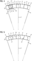
- the representation after figure 4 shows the positioning of the electrical conductors and intermediate pieces in a section of the active part in a front cross-section in the form of a piece of cake.
- the intermediate bodies 4,4 ' , 4 " , 4"' are located between the electrical conductors 3,3 ' , 3 " , 3 '' ' .
- the electrical conductors contain, in particular, copper.
- the intermediate bodies include, in particular, iron and/or steel. Both are printed.
- contact layers 5, 5 ' , 5 " , 5 ''' which in particular contain nickel.
- the contact layers have a serrated pattern 16, 16 ' .
- the electrical conductors and the intermediate bodies are printed on a shaft body Printing takes place from the inside to the outside, which is illustrated by the radial direction 17.
- the width 9.9 ′ , 9 ′′ , 9 ′′′ of the electrical conductors changes outwards in the circumferential direction.
- the width of the intermediate bodies also changes in the same radial position.
- the jagged shape results in a particularly good hold within a pressure layer 22 .
- FIG 5 shows in a similar way as figure 4 the cross section of a section of an active part, the boundary area between the electrical conductors and the intermediate body not being shown, but running in a wavy manner.
- the representation according to Figures 6 to 9 shows the sequence of printing operations.
- a layer of the electrical conductors 3,3 ' ,3 " ,3 “' is printed onto the shaft body 6. These electrical conductors are spaced apart from one another.
- layers of the intermediate bodies 4,4 ' ,4 " ,4 ''' printed, extending radially outward over the first layer of electrical conductors result.
- the electrical conductors are then printed in layers so that they also rise radially outwards over the intermediate bodies. This results in levels 20.
- step 9 the intermediate bodies are then initially printed further radially outwards until the electrical conductors are then printed outwards in such a way that there are no longer any steps.
- This step-by-step procedure forms layers 19, 19 ' .
- the representation according to Figures 10 to 13 shows the sequence of printing processes, according to that already in the Figures 6 to 9 shown sequence.
- the electrical conductors have a rounded shape and reflect how electrical conductors and intermediate bodies can be connected to one another through their shape in order to absorb centrifugal forces. It is shown that here too the width 18 of a formed electrical conductor changes alternately radially outwards, ie once larger it becomes smaller again and then larger again or vice versa.
Abstract
Ein Aktivteil (1) einer elektrischen Maschine (10), weist elektrische Leiter (3,3',3",3"') auf, wobei die elektrischen Leiter (3,3',3",3"') gedruckt sind, wobei zwischen den elektrischen Leitern (3,3',3",3"') ein Zwischenkörper (4,4',4",4"') ist. Bei einem Verfahren zur Herstellung eines Aktivteils (1) einer elektrischen Maschine, werden elektrische Leiter (3,3',3",3"') gedruckt, wobei zwischen elektrischen Leitern (3,3',3",3"') ein Zwischenkörper (4,4',4",4"') gedruckt wird, wobei zwischen dem Druck zumindest eines elektrischen Leiters (3,3',3",3"') und eines Zwischenkörper (4,4',4",4"') abgewechselt wird.An active part (1) of an electrical machine (10) has electrical conductors (3,3',3",3"'), the electrical conductors (3,3',3",3"') being printed, there being an intermediate body (4,4',4",4"') between the electrical conductors (3,3',3",3"'). In a method for producing an active part (1) of an electrical machine, electrical conductors (3,3',3",3"') are printed, with a Intermediate body (4,4',4",4"') is printed, with at least one electrical conductor (3,3',3",3"') and an intermediate body (4,4',4", 4"') is alternated.
Description
Die Erfindung betrifft einen Aktivteil einer elektrischen Maschine und ein Verfahren zur Herstellung dessen.The invention relates to an active part of an electrical machine and a method for producing it.
Eine elektrische Maschine weist einen Stator und einen Rotor auf. Ist die elektrische Maschine eine Asynchronmaschine, ist im Betrieb der elektrischen Maschine sowohl der Stator wie auch der Rotor bestromt. Damit ist der Rotor auch ein Aktivteil der elektrischen Maschine, da dieser einen Kurzschlusskäfig aufweist, welcher Leiter aufweist, durch welchen im Betrieb der elektrischen Maschine elektrischer Strom fließt.An electrical machine has a stator and a rotor. If the electrical machine is an asynchronous machine, both the stator and the rotor are energized during operation of the electrical machine. The rotor is therefore also an active part of the electric machine, since it has a squirrel cage which has conductors through which electric current flows during operation of the electric machine.
Der Rotor der elektrischen Maschine, also das Aktivteil der Asynchronmaschine welches sich im Betrieb dreht, ist im Betrieb Fliehkräften ausgesetzt. Leiter des Aktivteils, also insbesondere Leiter des Kurzschlusskäfigs sind so auszuführen bzw. zu konstruieren, dass diese den Fliehkräften standhalten. Ein spezifisches Problem besteht beispielsweise darin, eine Verbindung (bspw. zur Herstellung von Komponenten für elektrische Maschinen, wie zum Beispiel dem Rotor einer Asynchronmaschine als deren Aktivteil) unter Verwendung unterschiedlicher Materialien (bspw. Kuper / Eisen oder Kupfer / Stahl oder Eisen / Stahl) stabil auszuführen. Dies gelingt beispielsweise durch stoffschlüssige Verbindungen. Eine solche stoffschlüssige Verbindung wurde bisher bspw. für Käfigläufer von Asynchronmaschinen gefertigt. Diese Läufer erfordern kurzgeschlossene Rotorwicklungen, um ihre Funktion zu erfüllen. Der bestromte Stator induziert im Rotor Ströme, die mit dem Feld des Stators ein Drehmoment bewirken und so eine Last antreiben. Bei Hochdrehzahlantrieben ist der Rotor, aus Gründen der mechanischen Festigkeit, aus massivem, hochfestem Stahl mit integrierter Kurzschluss-Rotorwicklung. Zur Integration der Rotorwicklung werden zunächst Nuten für die Stäbe bzw. die Ringsegmente der Wicklung in den massiven Rotorballen gefräst bzw. gedreht und dort anschließend massive, vernickelte Kupferstäbe/-ringsegmente eingefügt. Durch die anschließende Anwendung eines isostatischen Heißpressverfahrens (HIP: Hot Isostatic Pressing) entsteht eine Diffusionszone zwischen dem Kupfer der Stäbe und dem Nickel der Beschichtung, sowie zwischen dem Nickel der Beschichtung und dem Stahl des massiven Rotors. Diese hochfeste Verbindung ist notwendig, um den Fliehkraft-Beanspruchungen bei höchsten Drehzahlen Stand zu halten. Der HIP-Prozess erfordert hohe Temperaturen und Drücke. Das beschriebene Verfahren ist sehr aufwendig und teuer.The rotor of the electrical machine, i.e. the active part of the asynchronous machine which rotates during operation, is exposed to centrifugal forces during operation. Conductors of the active part, i.e. in particular conductors of the squirrel cage, must be designed or constructed in such a way that they withstand the centrifugal forces. A specific problem is, for example, a connection (e.g. for the production of components for electrical machines, such as the rotor of an asynchronous machine as its active part) using different materials (e.g. copper / iron or copper / steel or iron / steel) run stably. This is achieved, for example, by material connections. Such an integral connection was previously made, for example, for squirrel-cage rotors of asynchronous machines. These rotors require shorted rotor windings to perform their function. The energized stator induces currents in the rotor, which cause a torque with the stator field and thus drive a load. For reasons of mechanical strength, the rotor of high-speed drives is made of solid, high-strength steel with an integrated short-circuit rotor winding. To integrate the rotor winding, grooves for the rods or the ring segments of the winding are first milled or turned in the solid rotor body and then solid, nickel-plated copper rods/ring segments inserted. The subsequent application of a hot isostatic pressing process (HIP: Hot Isostatic Pressing) creates a diffusion zone between the copper of the rods and the nickel of the coating, and between the nickel of the coating and the steel of the solid rotor. This high-strength connection is necessary to withstand the centrifugal stresses at the highest speeds. The HIP process requires high temperatures and pressures. The method described is very complicated and expensive.
Eine Aufgabe der Erfindung ist es ein Aktivteil der elektrischen Maschine, insbesondere einen Rotor der elektrischen Maschine einfach und stabil auszuführen. Damit soll erreicht werden, dass das Aktivteil bei Rotation nicht zerstört wird.One object of the invention is to design an active part of the electrical machine, in particular a rotor of the electrical machine, in a simple and stable manner. This is to ensure that the active part is not destroyed during rotation.
Eine Lösung der Aufgabe ergibt sich bei einem Aktivteil nach Anspruch 1. Eine weitere Lösung der Aufgabe ergibt sich bei einem Verfahren nach Anspruch 8. weitere Ausgestaltungen ergeben sich gemäß der Ansprüche 2 bis 7 und 9 bis 12.A solution to the problem results from an active part according to claim 1. A further solution to the problem results from a method according to claim 8. Further configurations result from claims 2 to 7 and 9 to 12.
Ein Aktivteil einer elektrischen Maschine, welches elektrische Leiter aufweist, weist elektrische Leiter auf, welche gedruckt sind. Das Aktivteil der elektrischen Maschine ist insbesondere ein Rotor der elektrischen Maschine. Die elektrische Maschine ist insbesondere eine Asynchronmaschine. Der gedruckte elektrische Leiter ist insbesondere ein Leiter eines Kurzschlusskäfigs der Asynchronmaschine. Zwischen den gedruckten elektrischen Leiter befindet sich ein Zwischenkörper. Die Zwischenkörper weisen eine zu den elektrischen Leitern unterschiedliche und geringere elektrische Leitfähigkeit auf. Durch das Drucken der elektrischen Leiter kann eine feste Verbindung hergestellt werden. Die gedruckten elektrischen Leiter weisen eine Längsausrichtung parallel zur Rotationsachse des Rotors auf. Zum gedruckten elektrischen Leiter kann beispielsweise Kupfer und/oder Aluminium verwendet werden.An active part of an electrical machine, which has electrical conductors, has electrical conductors that are printed. The active part of the electrical machine is in particular a rotor of the electrical machine. The electrical machine is in particular an asynchronous machine. The printed electrical conductor is in particular a conductor of a squirrel cage of the asynchronous machine. There is an intermediate body between the printed electrical conductors. The intermediate bodies have a different and lower electrical conductivity than the electrical conductors. By printing the electrical conductors, a firm connection can be made. The printed electrical conductors have a longitudinal orientation parallel to the axis of rotation of the rotor. For example, copper and/or aluminum can be used for the printed electrical conductor.
In einer Ausgestaltung des Aktivteils sind elektrische Leiter gedruckt wie auch Zwischenkörper zwischen den elektrischen Leitern. Auch dies erhöht die Festigkeit.In one configuration of the active part, electrical conductors are printed, as are intermediate bodies between the electrical conductors. This also increases strength.
In einer Ausgestaltung des Aktivteils sind die elektrischen Leiter symmetrisch über den Umfang des Rotors (Aktivteil) positioniert.In one configuration of the active part, the electrical conductors are positioned symmetrically over the circumference of the rotor (active part).
In einer Ausgestaltung des Aktivteils weist zumindest einer der elektrischen Leiter in einem Abschnitt einen Querschnitt auf, welcher sich mit zunehmendem Radius verjüngt. Der Radius betrifft dabei die Rotationsachse des Aktivteils (Rotors). Verjüngt sich der Querschnitt radial nach außen kann der gedruckte elektrische Leiter doch angrenzende Zwischenkörper gehalten werden. Dies ergibt sich aus der geometrischen Form, wenn sich die Zwischenkörper in Umfangsrichtung jeweils an die elektrischen Leiter mittelbar oder unmittelbar anschließend. Ein mittelbares Anschließen ergibt sich beispielsweise dadurch, wenn sich zwischen den elektrischen Leiter und dem Zwischenkörper noch eine Zwischenschicht befindet. Dies ist beispielsweise aus einem Material, welches Mittel aufweist. Die Zwischenkörper sind beispielsweise aus einem Material, welches Stahl und/oder Eisen aufweist. Verjüngt sich der Querschnitt eines gedruckten elektrischen Leiters, so verjüngt sich dieser insbesondere in einer Tangentialrichtung. Der Querschnitt ergibt sich aus einer stirnseitigen Sicht auf die elektrischen Leiter bzw. die Zwischenkörper.In one configuration of the active part, at least one of the electrical conductors has a cross section in a section that tapers with increasing radius. The radius relates to the axis of rotation of the active part (rotor). If the cross section tapers radially outwards, the printed electrical conductor can still be held on adjacent intermediate bodies. This results from the geometric shape when the intermediate bodies are each directly or indirectly connected to the electrical conductors in the circumferential direction. An indirect connection results, for example, when there is an intermediate layer between the electrical conductor and the intermediate body. This is, for example, made of a material which has means. The intermediate bodies are made, for example, from a material that includes steel and/or iron. If the cross section of a printed electrical conductor tapers, it tapers in particular in a tangential direction. The cross section results from an end view of the electrical conductors or the intermediate bodies.
In einer Ausgestaltung des Aktivteils nimmt der Querschnitt in seiner Tangentialausdehnung radial nach außen abwechselnd zu und ab bzw. ab und zu. Dies trifft ebenso den Querschnitt bezüglich der tangentialen Ausdehnung der Zwischenkörper. Dabei ergibt es sich in einer Ausgestaltung, dass dort, wo sich der Querschnitt des gedruckten elektrischen Leiters in einer radialen Richtung verjüngt sich in entsprechender Weise der Querschnitt des Zwischenkörpers vergrößert und umgekehrt. Damit ergibt sich insbesondere eine Verzahnung von elektrischen Leitern und Zwischenkörpern, wobei auch die Zwischenkörper gedruckt ausgeführt sein können.In one configuration of the active part, the cross section alternately increases and decreases or decreases and increases radially outwards in its tangential extent. This also applies to the cross section with regard to the tangential extension of the intermediate bodies. In one embodiment, the result is that where the cross section of the printed electrical conductor tapers in a radial direction, the cross section of the intermediate body increases in a corresponding manner and vice versa. This results in particular in an interlocking of electrical Conductors and intermediate bodies, the intermediate body can also be printed.
In einer Ausgestaltung des Aktivteils ist in dieses folglich derart ausführbar, dass zumindest einer der elektrischen Leiter eine Vielzahl von Abschnitten mit Querschnitten aufweist, welche sich mit zunehmendem Radius verjüngen. Dabei entsprechen die Abschnitte beispielsweise zumindest teilweise Abschnitte eines Drucks der elektrischen Leiter, wobei die elektrischen Leiter abwechselnd zu den Zwischenkörper radial zunehmend aufgedruckt werden.In one configuration of the active part, it can consequently be designed in such a way that at least one of the electrical conductors has a multiplicity of sections with cross sections which taper with increasing radius. The sections correspond, for example, at least in part to sections of a print of the electrical conductors, with the electrical conductors being printed on alternately to the intermediate body, increasing radially.
In einer Ausgestaltung des Aktivteils ist zwischen zumindest einem der gedruckten elektrischen Leiter und dem gedruckten Zwischenkörper eine dreidimensionale Struktur ausgebildet. Diese dreidimensionale Struktur ist beispielsweise im Querschnitt gezackt oder gewellt. So ergibt sich eine Formpassung zwischen den Zwischenkörper und den elektrischen Leitern sodass diese besser in Position gehalten werden können, auch wenn Kräfte radial nach Außen auf diese wirken.In one configuration of the active part, a three-dimensional structure is formed between at least one of the printed electrical conductors and the printed intermediate body. This three-dimensional structure is jagged or wavy in cross section, for example. This results in a form fit between the intermediate body and the electrical conductors so that they can be held in position better, even when forces act on them radially outwards.
In einer Ausgestaltung des Aktivteils weist die dreidimensionale Struktur in einem Querschnitt also ein Zackenmuster oder ein Wellenmuster auf.In one configuration of the active part, the three-dimensional structure thus has a jagged pattern or a wave pattern in a cross section.
In einer Ausgestaltung des Aktivteils differiert die elektrische Leitfähigkeit der elektrischen Leiter radial. Die elektrische Leitfähigkeit ist insbesondere in Bereichen größer, welche einen größeren Radius, d. h. einen größeren Abstand von der Rotationsachse, aufweisen. So kann der Widerstand der elektrischen Leiter eingestellt werden und auch der Skinneffekt berücksichtigt werden. Beispielsweise kann auch die elektrische Leitfähigkeit radial nach außen abnehmen.In one configuration of the active part, the electrical conductivity of the electrical conductors differs radially. The electrical conductivity is particularly greater in areas that have a larger radius, i. H. have a greater distance from the axis of rotation. In this way, the resistance of the electrical conductors can be adjusted and the skin effect can also be taken into account. For example, the electrical conductivity can also decrease radially outwards.
In einer Ausgestaltung des Aktivteils weisen die elektrischen Leiter und/oder die insbesondere gedruckten Zwischenkörper zwischen zwei der elektrischen Leiter, Schichten auf, welche radial dort enden bzw. beginnen, an welchen die Dicke eines der elektrischen Leiters, bzw. Zwischenkörpers ein lokales Minimum oder Maximum aufweist. Die Schichtung ergibt sich daraus, dass die elektrischen Leiter bzw. die Zwischenkörper radial nach außen schichtweise aufgedruckt werden. Die radiale Dicke der elektrischen Leiter und der Zwischenkörper vergrößert sich also alternierend (abwechselnd). Damit ist es möglich die Wellenform bzw. die Zackenform herzustellen, welche zusätzlichen Halt gibt.In one configuration of the active part, the electrical conductors and/or the particularly printed intermediate bodies between two of the electrical conductors have layers which end or begin radially there, at which the thickness of a of the electrical conductor or intermediate body has a local minimum or maximum. The layering results from the fact that the electrical conductors or the intermediate bodies are printed in layers radially outward. The radial thickness of the electrical conductors and the intermediate body thus increases alternately (alternately). This makes it possible to produce the wave shape or jagged shape, which gives additional support.
In einem Verfahren zur Herstellung eines Aktivteils, insbesondere eines Rotors mit einem Kurzschlusskäfig, einer elektrischen Maschine, werden die elektrische Leiter gedruckt, wobei zwischen elektrischen Leitern ein Zwischenkörper gedruckt wird, wobei zwischen dem Druck zumindest eines elektrischen Leiters und eines Zwischenkörper abgewechselt wird. So ergibt sich ein schichtweiser Aufbau von elektrischen Leitern bzw. Zwischenkörper. Der Kurzschlusskäfig des Aktivteils (Rotors) der Asynchronmaschine ist insbesondere additiv so zu fertigen, dass eine stoffschlüssige Verbindung zwischen den Materialien entsteht. Der Stoffschluss ist notwendig, um hohe Festigkeiten im Interface der Verbindung, und somit zwischen den Stoffen, gewähren zu können. Dies gelingt beispielsweise mittels eines Kaltgasspritzverfahrens. Mittels des Kaltgasspritzverfahrens lässt sich elektrisch leitendes Material wie Kupfer oder Aluminium aber auch magnetisierbares Material wie Eisen drucken. Der Kurzschlusskäfig der Asynchronmaschine kann also teilweise oder vollständig mittels eines additiven Druckverfahrens wie das "Kaltgasspritzen" hergestellt werden. Dazu wird der Leiterwerkstoff (bspw. Kupfer oder Aluminium) für die Wicklung und ein weichmagnetischer Werkstoff (bspw. FeSi2,9) für die Zähne schichtweise so auf eine Welle gedruckt, dass die Leiter und die Zähle parallel aufgebaut werden. Zusätzlich wird zum Beispiel parallel dazu zwischen Leiter-, Zahn- und Wellenwerkstoff eine im Vergleich sehr dünne Schicht (<= 300 µm) eines dritten Materials bspw. Nickel gedruckt. Diese zusätzliche Schicht (auch Diffusionsschicht genannt) dient der Ausbildung einer Diffusionszone. Die Diffusionszone erhöht die Bindung zwischen den angrenzenden Materialien. Der Zahn ist ein Beispiel für einen Zwischenkörper zwischen den elektrischen Leitern, welche kurzgeschlossene Wicklungen ausbilden. In einer möglichen anschließenden Wärmebehandlung (bspw. 6h bei 400°C) bildet sich dann insbesondere zwischen Leiterwerkstoff und Diffusionsschicht, zwischen Diffusionsschicht und weichmagnetischem Werkstoff sowie zwischen Diffusionsschicht und Stahl des massiven Rotors eine Diffusionszone und somit eine hochfeste Verbindung zwischen den unterschiedlichen Werkstoffen aus. Ggf. kann es aus prozesstechnischen- und / oder Genauigkeitsgründen notwendig sein, zwischen den additiv aufgebauten Werkstoffen eine subtraktive Zwischenbearbeitung durchzuführen. Das beschriebene Verfahren bzw. die beschriebenen Verfahren sind nicht ausschließlich auf Asynchronmaschinen mit massiven Rotoren beschränkt. Rotoren können beispielsweise auch Teil massiv ausgebildet werden.In a method for producing an active part, in particular a rotor with a squirrel cage, of an electrical machine, the electrical conductors are printed, with an intermediate body being printed between electrical conductors, with the printing of at least one electrical conductor and an intermediate body being alternated. This results in a layered structure of electrical conductors or intermediate bodies. The squirrel-cage cage of the active part (rotor) of the asynchronous machine must be manufactured additively in such a way that a material bond is created between the materials. The material connection is necessary in order to be able to guarantee high strength in the interface of the connection, and thus between the materials. This is achieved, for example, by means of a cold gas spraying process. The cold gas spraying process can be used to print electrically conductive material such as copper or aluminum, but also magnetizable material such as iron. The squirrel-cage cage of the asynchronous machine can therefore be produced partially or completely using an additive printing process such as "cold gas spraying". For this purpose, the conductor material (e.g. copper or aluminum) for the winding and a soft magnetic material (e.g. FeSi2.9) for the teeth are printed in layers onto a shaft in such a way that the conductor and the counter are built up in parallel. In addition, a comparatively very thin layer (<= 300 µm) of a third material, e.g. nickel, is printed in parallel between the conductor, tooth and shaft material. This additional layer (also called diffusion layer) serves to form a diffusion zone. The diffusion zone increases the bonding between the adjacent ones Materials. The tooth is an example of an intermediate body between the electrical conductors that form short-circuited windings. In a possible subsequent heat treatment (e.g. 6 hours at 400°C), a diffusion zone is then formed in particular between the conductor material and the diffusion layer, between the diffusion layer and the soft magnetic material and between the diffusion layer and the steel of the massive rotor, and thus a high-strength connection between the different materials. It may be necessary for process engineering and/or accuracy reasons to carry out subtractive intermediate processing between the additively built materials. The method or methods described are not exclusively limited to asynchronous machines with solid rotors. Rotors can also be made partially solid, for example.
In einer Ausgestaltung des Verfahrens wird in einem Verfahrensschritt ein erster elektrischer Leiter und ein zweiter benachbarter elektrischer Leiter gedruckt, wobei deren Breite abnimmt, wobei in einem nachfolgenden Verfahrensschritt der Zwischenkörper zwischen dem ersten elektrischen Leiter und dem zweiten elektrischen Leiter gedruckt wird, wobei dessen Breite zunimmt. So ergeben sich unterschiedliche Dicken der Querschnitte der gedruckten Elemente.In one configuration of the method, a first electrical conductor and a second adjacent electrical conductor are printed in one method step, with their width decreasing, with the intermediate body between the first electrical conductor and the second electrical conductor being printed in a subsequent method step, with its width increasing . This results in different thicknesses of the cross sections of the printed elements.
In einer Ausgestaltung des Verfahrens sind die elektrischen Leiter und/oder die Zwischenkörper auf eine Wellenkörper gedruckt. Diese ist insbesondere derart massiv aufgebaut, dass er von auftretenden Fliehkräften unbeeinflusst ist.In one embodiment of the method, the electrical conductors and/or the intermediate bodies are printed onto a corrugated body. In particular, this is constructed so massively that it is unaffected by centrifugal forces that occur.
In einer Ausgestaltung des Verfahrens wird zwischen einem Druck zumindest eines Teils eines der elektrischen Leiter, welche ein erster Druckgegenstand sind und dem Druck zumindest eines Teils der Zwischenkörper, welche ein zweiter Druckgegenstand sind, derart abgewechselt, dass sich vor einem Wechsel ein radialer Dickenzuwachs des elektrischen Leiters oder des Zwischenkörpers ergibt der zwischen größer gleich 50 % und kleiner gleich 200 % des darauf folgenden radialen Dickenzuwachses des jeweils anderen Druckgegenstandes ist.In one embodiment of the method, printing of at least part of one of the electrical conductors, which is a first printed object, and printing of at least part of the intermediate bodies, which are a second printed object, are alternated in such a way that before a change, a radial increase in thickness of the electrical Conductor or the intermediate body results in the between larger is equal to 50% and less than or equal to 200% of the subsequent radial increase in thickness of the other printed object in each case.
Die beschriebene Methode birgt eine Vereinfachung der Fertigung und eine deutliche Erhöhung des Automatisierungsgrads (>80% möglich) gegenüber dem bestehenden Füge-/HIP-Verfahren. Darüber hinaus impliziert sie die Möglichkeit individuelle Läufergeometrie, angepasst auf spezielle Anforderungen des Kunden (Rotorstab-Geometrien) zu realisieren, die mit herkömmlichen Methoden nicht oder nur mit äußerst hohem Aufwand fertigbar sind. Zudem können einem Rotorstab, also einem elektrischen Leiter des Aktivteils, lokal besondere elektrische Materialeigenschaften, wie z.B. unterschiedliche elektrische Leitfähigkeiten gegeben werden.The method described simplifies production and significantly increases the degree of automation (>80% possible) compared to the existing joining/HIP process. In addition, it implies the possibility of realizing individual rotor geometries, adapted to special customer requirements (rotor bar geometries), which cannot be produced with conventional methods or can only be produced with extremely great effort. In addition, a rotor bar, i.e. an electrical conductor of the active part, can be given special electrical material properties locally, such as different electrical conductivities.
Im Folgenden wird die Erfindung beispielhaft anhand von Figuren näher dargestellt und erläutert. Die in den Figuren gezeigten Merkmale können auch zu neuen Ausführungsformen kombiniert werden, ohne die Erfindung zu verlassen. Gleiche Bezugszeichen bezeichnen gleichartige Elemente. Es zeigen:
- FIG 1
- eine elektrische Maschine;
- FIG 2
- Nuten;
- FIG 3
- Nutenformen;
- FIG 4
- eine erste Form von gedruckten elektrischen Leitern;
- FIG 5
- eine zweite Form von gedruckten elektrischen Leitern.
- FIG 6 bis FIG 9
- eine erste Abfolge eines Druckvorgangs und
- FIG 10 bis FIG 13
- eine zweite Abfolge eines Druckvorgangs.
- FIG 1
- an electric machine;
- FIG 2
- grooves;
- 3
- groove shapes;
- FIG 4
- a first form of printed electrical conductors;
- 5
- a second form of printed electrical conductors.
- 6 to 9
- a first sequence of printing and
- 10 to 13
- a second sequence of printing.
Die Darstellung nach
Die Darstellung nach
Die Darstellung nach
Die Darstellung nach
Die Darstellung gemäß
Die Darstellung gemäß der
Die Darstellung gemäß der
Claims (12)
Priority Applications (5)
| Application Number | Priority Date | Filing Date | Title |
|---|---|---|---|
| EP20193655.6A EP3961880A1 (en) | 2020-08-31 | 2020-08-31 | Active part of an electric machine with printed conductor |
| PCT/EP2021/073442 WO2022043353A1 (en) | 2020-08-31 | 2021-08-25 | Active part of an electric machine, having a printed conductor |
| CN202180073891.1A CN116458045A (en) | 2020-08-31 | 2021-08-25 | Active component of an electric machine with printed conductors |
| EP21769387.8A EP4183033A1 (en) | 2020-08-31 | 2021-08-25 | Active part of an electric machine, having a printed conductor |
| US18/023,627 US11804756B2 (en) | 2020-08-31 | 2021-08-25 | Active part of an electric machine, having a printed conductor |
Applications Claiming Priority (1)
| Application Number | Priority Date | Filing Date | Title |
|---|---|---|---|
| EP20193655.6A EP3961880A1 (en) | 2020-08-31 | 2020-08-31 | Active part of an electric machine with printed conductor |
Publications (1)
| Publication Number | Publication Date |
|---|---|
| EP3961880A1 true EP3961880A1 (en) | 2022-03-02 |
Family
ID=72292400
Family Applications (2)
| Application Number | Title | Priority Date | Filing Date |
|---|---|---|---|
| EP20193655.6A Withdrawn EP3961880A1 (en) | 2020-08-31 | 2020-08-31 | Active part of an electric machine with printed conductor |
| EP21769387.8A Pending EP4183033A1 (en) | 2020-08-31 | 2021-08-25 | Active part of an electric machine, having a printed conductor |
Family Applications After (1)
| Application Number | Title | Priority Date | Filing Date |
|---|---|---|---|
| EP21769387.8A Pending EP4183033A1 (en) | 2020-08-31 | 2021-08-25 | Active part of an electric machine, having a printed conductor |
Country Status (4)
| Country | Link |
|---|---|
| US (1) | US11804756B2 (en) |
| EP (2) | EP3961880A1 (en) |
| CN (1) | CN116458045A (en) |
| WO (1) | WO2022043353A1 (en) |
Citations (3)
| Publication number | Priority date | Publication date | Assignee | Title |
|---|---|---|---|---|
| DE102012006248A1 (en) * | 2011-04-04 | 2012-10-04 | Fanuc Corporation | Squirrel cage and its manufacturing process |
| JP2014108006A (en) * | 2012-11-29 | 2014-06-09 | Toyota Industries Corp | Rotor, induction motor including rotor, and manufacturing method of rotor |
| EP3629452A1 (en) * | 2018-09-28 | 2020-04-01 | Siemens Aktiengesellschaft | Method for the preparation of a rotor of a rotary electric machine |
Family Cites Families (18)
| Publication number | Priority date | Publication date | Assignee | Title |
|---|---|---|---|---|
| US3456144A (en) * | 1962-09-20 | 1969-07-15 | Printed Motors Inc | Printed-circuit multilayer winding for electric rotary machines |
| DE2409681A1 (en) * | 1974-02-28 | 1975-09-11 | Retobobina Handelsanstalt | ELECTRIC ANCHOR WRAP |
| DE602004013722D1 (en) * | 2003-02-07 | 2008-06-26 | Core Motion Inc | OPTIMIZED LADDER ASSEMBLY FOR AN AXIAL FIELD TURNING EQUIPMENT |
| NL2011129C2 (en) * | 2013-07-09 | 2015-01-12 | Eco Logical Entpr B V | COMPACT ELECTRICAL DEVICE AND ELECTRODYNAMIC LOUDSPEAKER, ELECTRIC MOTOR, SCREENER AND ADJUSTABLE COUPLING BASED ON THEM. |
| EP2999092A1 (en) * | 2014-09-18 | 2016-03-23 | ABB Technology AG | Insulation of a wound conductor and method for insulating such a conductor |
| US10170953B2 (en) * | 2015-10-02 | 2019-01-01 | E-Circuit Motors, Inc. | Planar composite structures and assemblies for axial flux motors and generators |
| US9673684B2 (en) * | 2015-10-02 | 2017-06-06 | E-Circuit Motors, Inc. | Structures and methods for thermal management in printed circuit board stators |
| EP3255758A1 (en) | 2016-06-07 | 2017-12-13 | Siemens Aktiengesellschaft | Rotor for a reluctance machine |
| EP3297131A1 (en) | 2016-09-19 | 2018-03-21 | Siemens Aktiengesellschaft | Rotor for an electric rotating machine |
| GB2577288A (en) * | 2018-09-20 | 2020-03-25 | Rolls Royce Plc | Electrical machine winding assembly and method of manufacture thereof |
| JP7293627B2 (en) * | 2018-12-05 | 2023-06-20 | 株式会社デンソー | Rotating electric machine and manufacturing method of rotating electric machine |
| EP3723244A1 (en) * | 2019-04-08 | 2020-10-14 | Siemens Aktiengesellschaft | Winding head assembly for an electric rotating machine |
| US11283319B2 (en) * | 2019-11-11 | 2022-03-22 | Infinitum Electric, Inc. | Axial field rotary energy device with PCB stator having interleaved PCBS |
| US20220149019A1 (en) * | 2019-12-06 | 2022-05-12 | Osram Opto Semiconductors Gmbh | Optoelectronic device |
| DE102021102753B4 (en) * | 2021-02-05 | 2023-05-25 | Ford Global Technologies Llc | electrical machine |
| JP2022162384A (en) * | 2021-04-12 | 2022-10-24 | Tdk株式会社 | Coil type electronic component |
| CN115706498A (en) * | 2021-08-06 | 2023-02-17 | 福特全球技术公司 | Electrical steel sheet for electric machine and method for producing electrical steel sheet |
| EP4181637A1 (en) * | 2021-11-15 | 2023-05-17 | AT & S Austria Technologie & Systemtechnik Aktiengesellschaft | Component carrier with a via containing a hardened filling material |
-
2020
- 2020-08-31 EP EP20193655.6A patent/EP3961880A1/en not_active Withdrawn
-
2021
- 2021-08-25 WO PCT/EP2021/073442 patent/WO2022043353A1/en active Application Filing
- 2021-08-25 US US18/023,627 patent/US11804756B2/en active Active
- 2021-08-25 CN CN202180073891.1A patent/CN116458045A/en active Pending
- 2021-08-25 EP EP21769387.8A patent/EP4183033A1/en active Pending
Patent Citations (3)
| Publication number | Priority date | Publication date | Assignee | Title |
|---|---|---|---|---|
| DE102012006248A1 (en) * | 2011-04-04 | 2012-10-04 | Fanuc Corporation | Squirrel cage and its manufacturing process |
| JP2014108006A (en) * | 2012-11-29 | 2014-06-09 | Toyota Industries Corp | Rotor, induction motor including rotor, and manufacturing method of rotor |
| EP3629452A1 (en) * | 2018-09-28 | 2020-04-01 | Siemens Aktiengesellschaft | Method for the preparation of a rotor of a rotary electric machine |
Also Published As
| Publication number | Publication date |
|---|---|
| CN116458045A (en) | 2023-07-18 |
| WO2022043353A1 (en) | 2022-03-03 |
| EP4183033A1 (en) | 2023-05-24 |
| US11804756B2 (en) | 2023-10-31 |
| US20230246527A1 (en) | 2023-08-03 |
Similar Documents
| Publication | Publication Date | Title |
|---|---|---|
| EP2577852B1 (en) | Cage rotor for an asynchronous machine and method for producing the cage rotor | |
| EP3248271B1 (en) | Rotor of an asynchronous machine | |
| EP3178155A1 (en) | Rotor, reluctance machine and method for manufacturing the rotor | |
| WO2016020359A1 (en) | Rotor and reluctance machine | |
| DE2521557A1 (en) | INDUCTION MOTOR WITH A ROTOR HAVING NUMEROUS CAGEFUL ARRANGEMENTS AND METHOD OF MANUFACTURING | |
| EP3867998B1 (en) | Joining of a stack of metal sheets on a shaft | |
| DE102013113418A1 (en) | Method for manufacturing a stator core for rotating electrical machines | |
| EP3205004B1 (en) | Squirrel-cage rotor for an asynchronous electric machine having a support disk that stabilizes a short-circuit ring | |
| DE102015204872A1 (en) | Squirrel cage rotor for an electric asynchronous machine with a short-circuit ring stabilizing tie rods | |
| EP3961880A1 (en) | Active part of an electric machine with printed conductor | |
| EP2820746B1 (en) | Squirrel-cage rotor for a small motor and method for the production thereof | |
| DE102015202004A1 (en) | Squirrel-cage rotor with stable short-circuit ring for an electrical asynchronous machine and method of making the same | |
| WO2019228951A1 (en) | Cage rotor for an electric motor, in particular an asynchronous motor, electric motor and method for producing a cage rotor | |
| EP3657635A1 (en) | Rotor for an asynchronous machine with loss-optimised rod geometry, asynchronous machine and method | |
| EP4029133B1 (en) | Cage rotor and method for its production | |
| EP4277096A1 (en) | Rotor of a cage rotor motor and method for producing the same | |
| EP3393016A1 (en) | Short circuit rotor and method for producing a short circuit rotor | |
| EP3425779A1 (en) | Cage rotor for an asynchronous machine | |
| WO2021043365A1 (en) | Method for producing a rotor, rotor, and asynchronous motor | |
| DE3324687A1 (en) | Asynchronous machine with a double-cage armature winding | |
| DE102018208409A1 (en) | Squirrel cage rotor for an electric motor, in particular asynchronous motor, electric motor, and method for producing a shorting ring of a squirrel cage rotor | |
| EP3425778A1 (en) | Method for producing a short-circuit ring from a metal strip | |
| DE202018006590U1 (en) | Squirrel cage for an electric motor, in particular an asynchronous motor, electric motor | |
| WO2023150809A1 (en) | Method for producing an annular winding head support, and winding head support | |
| EP3979466A1 (en) | Electrical machine and system |
Legal Events
| Date | Code | Title | Description |
|---|---|---|---|
| PUAI | Public reference made under article 153(3) epc to a published international application that has entered the european phase |
Free format text: ORIGINAL CODE: 0009012 |
|
| STAA | Information on the status of an ep patent application or granted ep patent |
Free format text: STATUS: THE APPLICATION HAS BEEN PUBLISHED |
|
| AK | Designated contracting states |
Kind code of ref document: A1 Designated state(s): AL AT BE BG CH CY CZ DE DK EE ES FI FR GB GR HR HU IE IS IT LI LT LU LV MC MK MT NL NO PL PT RO RS SE SI SK SM TR |
|
| STAA | Information on the status of an ep patent application or granted ep patent |
Free format text: STATUS: THE APPLICATION IS DEEMED TO BE WITHDRAWN |
|
| 18D | Application deemed to be withdrawn |
Effective date: 20220903 |