EP3961845B1 - System und verfahren zur verwaltung eines von einem windpark erzeugten ausgabeflackerns - Google Patents
System und verfahren zur verwaltung eines von einem windpark erzeugten ausgabeflackerns Download PDFInfo
- Publication number
- EP3961845B1 EP3961845B1 EP21191952.7A EP21191952A EP3961845B1 EP 3961845 B1 EP3961845 B1 EP 3961845B1 EP 21191952 A EP21191952 A EP 21191952A EP 3961845 B1 EP3961845 B1 EP 3961845B1
- Authority
- EP
- European Patent Office
- Prior art keywords
- wind
- flicker
- output
- farm
- controller
- Prior art date
- Legal status (The legal status is an assumption and is not a legal conclusion. Google has not performed a legal analysis and makes no representation as to the accuracy of the status listed.)
- Active
Links
Images


Classifications
-
- F—MECHANICAL ENGINEERING; LIGHTING; HEATING; WEAPONS; BLASTING
- F03—MACHINES OR ENGINES FOR LIQUIDS; WIND, SPRING, OR WEIGHT MOTORS; PRODUCING MECHANICAL POWER OR A REACTIVE PROPULSIVE THRUST, NOT OTHERWISE PROVIDED FOR
- F03D—WIND MOTORS
- F03D17/00—Monitoring or testing of wind motors, e.g. diagnostics
-
- H—ELECTRICITY
- H02—GENERATION; CONVERSION OR DISTRIBUTION OF ELECTRIC POWER
- H02J—CIRCUIT ARRANGEMENTS OR SYSTEMS FOR SUPPLYING OR DISTRIBUTING ELECTRIC POWER; SYSTEMS FOR STORING ELECTRIC ENERGY
- H02J3/00—Circuit arrangements for AC mains or AC distribution networks
- H02J3/002—Flicker reduction, e.g. compensation of flicker introduced by non-linear load
-
- F—MECHANICAL ENGINEERING; LIGHTING; HEATING; WEAPONS; BLASTING
- F03—MACHINES OR ENGINES FOR LIQUIDS; WIND, SPRING, OR WEIGHT MOTORS; PRODUCING MECHANICAL POWER OR A REACTIVE PROPULSIVE THRUST, NOT OTHERWISE PROVIDED FOR
- F03D—WIND MOTORS
- F03D1/00—Wind motors with rotation axis substantially parallel to the air flow entering the rotor
- F03D1/02—Wind motors with rotation axis substantially parallel to the air flow entering the rotor having a plurality of rotors
-
- F—MECHANICAL ENGINEERING; LIGHTING; HEATING; WEAPONS; BLASTING
- F03—MACHINES OR ENGINES FOR LIQUIDS; WIND, SPRING, OR WEIGHT MOTORS; PRODUCING MECHANICAL POWER OR A REACTIVE PROPULSIVE THRUST, NOT OTHERWISE PROVIDED FOR
- F03D—WIND MOTORS
- F03D7/00—Controlling wind motors
- F03D7/02—Controlling wind motors the wind motors having rotation axis substantially parallel to the air flow entering the rotor
- F03D7/028—Controlling wind motors the wind motors having rotation axis substantially parallel to the air flow entering the rotor controlling wind motor output power
- F03D7/0284—Controlling wind motors the wind motors having rotation axis substantially parallel to the air flow entering the rotor controlling wind motor output power in relation to the state of the electric grid
-
- F—MECHANICAL ENGINEERING; LIGHTING; HEATING; WEAPONS; BLASTING
- F03—MACHINES OR ENGINES FOR LIQUIDS; WIND, SPRING, OR WEIGHT MOTORS; PRODUCING MECHANICAL POWER OR A REACTIVE PROPULSIVE THRUST, NOT OTHERWISE PROVIDED FOR
- F03D—WIND MOTORS
- F03D7/00—Controlling wind motors
- F03D7/02—Controlling wind motors the wind motors having rotation axis substantially parallel to the air flow entering the rotor
- F03D7/04—Automatic control; Regulation
- F03D7/042—Automatic control; Regulation by means of an electrical or electronic controller
- F03D7/048—Automatic control; Regulation by means of an electrical or electronic controller controlling wind farms
-
- F—MECHANICAL ENGINEERING; LIGHTING; HEATING; WEAPONS; BLASTING
- F03—MACHINES OR ENGINES FOR LIQUIDS; WIND, SPRING, OR WEIGHT MOTORS; PRODUCING MECHANICAL POWER OR A REACTIVE PROPULSIVE THRUST, NOT OTHERWISE PROVIDED FOR
- F03D—WIND MOTORS
- F03D80/00—Details, components or accessories not provided for in groups F03D1/00 - F03D17/00
-
- H—ELECTRICITY
- H02—GENERATION; CONVERSION OR DISTRIBUTION OF ELECTRIC POWER
- H02J—CIRCUIT ARRANGEMENTS OR SYSTEMS FOR SUPPLYING OR DISTRIBUTING ELECTRIC POWER; SYSTEMS FOR STORING ELECTRIC ENERGY
- H02J3/00—Circuit arrangements for AC mains or AC distribution networks
- H02J3/01—Arrangements for reducing harmonics or ripples
-
- H—ELECTRICITY
- H02—GENERATION; CONVERSION OR DISTRIBUTION OF ELECTRIC POWER
- H02J—CIRCUIT ARRANGEMENTS OR SYSTEMS FOR SUPPLYING OR DISTRIBUTING ELECTRIC POWER; SYSTEMS FOR STORING ELECTRIC ENERGY
- H02J3/00—Circuit arrangements for AC mains or AC distribution networks
- H02J3/38—Arrangements for parallely feeding a single network by two or more generators, converters or transformers
- H02J3/381—Dispersed generators
-
- H02J2101/28—
-
- H02J2105/16—
-
- Y—GENERAL TAGGING OF NEW TECHNOLOGICAL DEVELOPMENTS; GENERAL TAGGING OF CROSS-SECTIONAL TECHNOLOGIES SPANNING OVER SEVERAL SECTIONS OF THE IPC; TECHNICAL SUBJECTS COVERED BY FORMER USPC CROSS-REFERENCE ART COLLECTIONS [XRACs] AND DIGESTS
- Y02—TECHNOLOGIES OR APPLICATIONS FOR MITIGATION OR ADAPTATION AGAINST CLIMATE CHANGE
- Y02E—REDUCTION OF GREENHOUSE GAS [GHG] EMISSIONS, RELATED TO ENERGY GENERATION, TRANSMISSION OR DISTRIBUTION
- Y02E10/00—Energy generation through renewable energy sources
- Y02E10/70—Wind energy
- Y02E10/72—Wind turbines with rotation axis in wind direction
-
- Y—GENERAL TAGGING OF NEW TECHNOLOGICAL DEVELOPMENTS; GENERAL TAGGING OF CROSS-SECTIONAL TECHNOLOGIES SPANNING OVER SEVERAL SECTIONS OF THE IPC; TECHNICAL SUBJECTS COVERED BY FORMER USPC CROSS-REFERENCE ART COLLECTIONS [XRACs] AND DIGESTS
- Y02—TECHNOLOGIES OR APPLICATIONS FOR MITIGATION OR ADAPTATION AGAINST CLIMATE CHANGE
- Y02E—REDUCTION OF GREENHOUSE GAS [GHG] EMISSIONS, RELATED TO ENERGY GENERATION, TRANSMISSION OR DISTRIBUTION
- Y02E10/00—Energy generation through renewable energy sources
- Y02E10/70—Wind energy
- Y02E10/76—Power conversion electric or electronic aspects
Definitions
- the present disclosure relates in general to wind farms, and more particularly to systems and methods for managing output flicker generated by a wind farm having a plurality of wind turbines.
- Wind power is considered one of the cleanest, most environmentally friendly energy sources presently available, and wind turbines have gained increased attention in this regard.
- a modern wind turbine typically includes a tower, generator, gearbox, nacelle, and one or more rotor blades.
- the rotor blades capture kinetic energy of wind using known airfoil principles.
- rotor blades typically have the cross-sectional profile of an airfoil such that, during operation, air flows over the blade producing a pressure difference between the sides. Consequently, a lift force, which is directed from a pressure side towards a suction side, acts on the blade. The lift force generates torque on the main rotor shaft, which is geared to a generator for producing electricity.
- the generator may be electrically coupled to a bi-directional power converter that includes a rotor-side converter joined to a line-side converter via a regulated DC link.
- a bi-directional power converter that includes a rotor-side converter joined to a line-side converter via a regulated DC link.
- Such wind turbine power systems are generally referred to as a doubly-fed induction generator (DFIG).
- DFIG operation is typically characterized in that the rotor circuit is supplied with current from a current-regulated power converter.
- the wind turbine produces variable mechanical torque due to variable wind speeds and the power converter ensures this torque is converted into an electrical output at the same frequency of the grid.
- the low-speed shaft is configured to drive the gearbox that subsequently steps up the low rotational speed of the low-speed shaft to drive a high-speed shaft at an increased rotational speed.
- the high-speed shaft is generally coupled to the generator so as to rotatably drive a generator rotor.
- a rotating magnetic field may be induced by the generator rotor and a voltage may be induced within a generator stator.
- Rotational energy is converted into electrical energy through electromagnetic fields coupling the rotor and the stator, which is supplied to a power grid via a grid breaker.
- the main transformer steps up the voltage amplitude of the electrical power such that the transformed electrical power may be further transmitted to the power grid.
- flicker generally refers to variations in current or voltage on the power grid that are perceptible at certain frequencies (e.g. from about 1 Hertz (Hz) to about 30 Hz). Additionally, when the wind turbines are assembled as a wind farm, the flicker of the individual wind turbines, or a portion thereof, may be unintentionally synchronized resulting in an output flicker in the output of the wind farm. Oftentimes, grid requirements prohibit connection to the power grid if flicker is present in a certain amount.
- the invention is defined by a method for managing output flicker of a wind farm connected to a power grid with the steps of independent claim 1 and by a system for managing output flicker generated by a wind farm with the technical features of independent claim 11.
- the wind farm may also include at least one output sensor operably coupled to the farm controller at a point of interconnect (POI) with the power grid.
- detecting the parameter(s) indicative of the output flicker may also include monitoring via the output sensor(s) a frequency and amplitude of variations in current or voltage of the output of the wind farm at the point of interconnect with the power grid. The frequency and amplitude of the variations may be indicative of output flicker in the output of the wind turbine(s).
- the method may also include detecting, with the farm controller, an approach of the output of the output sensor(s) to a flicker threshold for the wind farm.
- the wind farm may include at least one environmental sensor operably coupled to the farm controller. Additionally, detecting the parameter(s) indicative of the output flicker may include monitoring, via the environmental sensor(s), at least one environmental parameter indicative of an environmental condition affecting the wind farm. The method may also include correlating, with the farm controller, the environmental parameter(s) to indicate an of a level of output flicker as detected by the output sensor(s) at the monitored environmental condition.
- the method may include determining, with the farm controller, an output flicker potential for the wind farm based at least in part on the correlation and a forecasted environmental condition.
- generating the command offset may include generating the command offset when at least one of the output flicker potential or the output of the output sensor(s) approaches or exceeds the flicker threshold for the wind farm.
- the method may include determining an impact on the level of output flicker resulting from the changing of the operating parameter of the wind turbine(s) based on the command offset.
- the method may also include correlating, with the farm controller, the impact with the environmental condition affecting the wind farm. Further, the method may include assigning a synchronicity-impact score to the wind turbine(s) based on the computed correlation for the detected environmental condition. Additionally, the method may include selecting the wind turbine(s) from the plurality of wind turbines to receive the command offset based, at least partially, on the synchronicity-impact score.
- detecting the parameter(s) indicative of the output flicker may include receiving, with the farm controller, a timing signal from the two wind turbines.
- the timing signal may be indicative of a rotor position for each of the wind turbines.
- the method may include determining, with the farm controller, a degree of synchronicity amongst the two wind turbines of the plurality of wind turbines based on the respective timing signals. Additionally, the method may include determining, with the farm controller, a difference between the degree of synchronicity and a synchronicity threshold corresponding to an output flicker threshold.
- determining the degree of synchronicity among the plurality of wind turbines may include establishing, with the farm controller, a plurality of time slices. The method may also include determining, with the farm controller, a standard deviation for the timing signals across the time slices. The standard deviation for the timing signals may be indicative of the degree of synchronicity amongst the plurality of wind turbines.
- the two wind turbines of the plurality of wind turbines may include at least a first sub-grouping of wind turbines and a second sub-grouping of wind turbines.
- the timing signal may be indicative of a combined timing of the first and second sub-groupings of wind turbines respectively.
- changing the operating parameter of the wind turbine(s) based on the command offset may include changing an operating parameter corresponding to at least one of generator torque, power output, rotor speed, or mechanical loading of the wind turbine(s).
- first, second, and third may be used interchangeably to distinguish one component from another and are not intended to signify location or importance of the individual components.
- Coupled refers to both direct coupling, as well as indirect coupling, through one or more intermediate components or features, unless otherwise specified herein.
- Approximating language is applied to modify any quantitative representation that could permissibly vary without resulting in a change in the basic function to which it is related. Accordingly, a value modified by a term or terms, such as “about”, “approximately”, and “substantially”, are not to be limited to the precise value specified. In at least some instances, the approximating language may correspond to the precision of an instrument for measuring the value, or the precision of the methods or machines for constructing or manufacturing the components and/or systems. For example, the approximating language may refer to being within a 10 percent margin.
- the present disclosure is directed to systems and methods for controlling a wind farm connected to power grid.
- the present invention includes a system and method which facilitate managing flicker occurring in the power grid generated by the wind farm.
- the flicker is be an output flicker resulting in the output of the wind farm resulting from the unintentional alignment/synchronization of the flicker that may be present in the outputs of the individual wind turbines of the wind farm.
- the farm controller detects a parameter of the wind farm, the indicative of a synchronized flicker of two or more wind turbines of the wind farm.
- the parameter may, for example, include measurements of the flicker, weather conditions, rotor position timing signals, learned wind turbine behaviors, and/or the wind turbine operational state.
- the farm controller In response to detecting the parameter, the farm controller generates a command offset for at least one of the wind turbines.
- the command offset may temporarily alter an operating state or parameter of the wind turbine. For example, when the rotors of two wind turbines pass through the six o'clock position at the same time, any flicker in the output of the wind turbines may be synchronized.
- the farm controller may direct one of the wind turbines to momentarily change its rotational speed so that the rotors of the two wind turbines pass through the six o'clock position at different instants.
- one of the wind turbines may, essentially, "skip a beat" so that the rotor positions, or other aspect of the turbines, are de-synchronized. Even though the individual wind turbines may produce an output having flicker, by de-synchronizing the flickers, the combined output of the wind farm delivered to the power grid may not flicker.
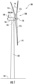
- FIG. 1 illustrates a perspective view of one embodiment of a wind turbine 100 according to the present disclosure.
- the wind turbine 100 generally includes a tower 102 extending from a support surface 104, a nacelle 106, mounted on the tower 102, and a rotor 108 coupled to the nacelle 106.
- the rotor 108 includes a rotatable hub 110 and at least one rotor blade 112 coupled to and extending outwardly from the hub 110.
- the rotor 108 includes three rotor blades 112.
- the rotor 108 may include more or less than three rotor blades 112.
- Each rotor blade 112 may be spaced about the hub 110 to facilitate rotating the rotor 108 to enable kinetic energy to be transferred from the wind into usable mechanical energy, and subsequently, electrical energy.
- the hub 110 may be rotatably coupled to an electric generator (not shown) positioned within the nacelle 106 to permit electrical energy to be produced.
- the wind turbine 100 may also include a controller 200 configured as a turbine controller 204.
- the controller 200 may be centralized within the nacelle 106. However, in other embodiments, the controller 200 may be located within any other component of the wind turbine 100 or at a location outside the wind turbine 100. Further, the controller 200 may be communicatively coupled to any number of the components of the wind turbine 100 in order to control the components. As such, the controller 200 may include a computer or other suitable processing unit.
- the turbine controller 204 may include suitable computer-readable instructions that, when implemented, configure the controller 200 to perform various different functions, such as receiving, transmitting and/or executing wind turbine control signals.
- one or more sensors 156, 158 may be provided on the wind turbine 100 to monitor the performance of the wind turbine 100 and/or environmental conditions affecting the wind turbine 100.
- the term "monitor" and variations thereof indicates that the various sensors of the wind turbine 100 may be configured to provide a direct measurement of the parameters being monitored or an indirect measurement of such parameters.
- the sensors described herein may, for example, be used to generate signals relating to the parameter being monitored, which can then be utilized by the controller 200 to determine the condition of the wind turbine 100.
- each of the wind turbines 100 may include an environmental sensor 158 configured for gathering data indicative of at least one environmental condition.
- the environmental sensor 158 may be operably coupled to the controller 200.
- the environmental sensor(s) 158 may, for example, be a wind vane, an anemometer, a lidar sensor, thermometer, barometer, or other suitable sensor.
- the data gathered by the environmental sensor(s) 158 may include measures of wind speed, wind direction, wind shear, wind gust, wind veer, atmospheric pressure, and/or temperature.
- the environmental sensor(s) 158 may be mounted to the nacelle 106 at a location downwind of the rotor 108.
- the environmental sensor(s) 158 may, in alternative embodiments, be coupled to, or integrated with, the rotor 108. It should be appreciated that the environmental sensor(s) 158 may include a network of sensors and may be positioned away from the wind turbines 100.
- the wind turbines 100 may also include one or more asset condition sensors 156.
- the asset condition sensor(s) 156 may, for example, be configured to monitor electrical properties of the output of the generator of each of the wind turbines 100, such as current sensors, voltage sensors temperature sensors, or power sensors that monitor power output directly based on current and voltage measurements.
- the asset condition sensor(s) 156 may include any other sensors that may be utilized to monitor the operating state of the wind turbines 100, such as rotor position and/or rotor timing.
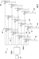
- the wind farm 152 may include a plurality of wind turbines 100 described herein and a controller 200.
- the controller 200 may be configured as a farm controller 202.
- the wind farm 152 may include twelve wind turbines 100.
- the wind farm 152 may include any other number of wind turbines 100, such as less than twelve wind turbines 100 or greater than twelve wind turbines 100.
- the turbine controller(s) 204 of the wind turbine(s) 100 may be communicatively coupled to the farm controller 202 through a wired connection, such as by connecting the controller(s) 200 through suitable communicative links 154 (e.g., a suitable cable).
- the controller(s) 200 may be communicatively coupled to the farm controller 202 through a wireless connection, such as by using any suitable wireless communications protocol known in the art.
- the farm controller 202 may be generally configured similar to the controller 200 for each of the individual wind turbines 100 within the wind farm 152.
- the farm controller 202 may also be operably coupled to at least one output sensor 162 at a point of interconnect with the power grid.
- the output sensor(s) 162 may be configured to monitor the output of the wind farm 152 in order to detect indications of output flicker in the output.
- FIGS. 3-5 schematic diagrams of multiple embodiments of a system 300 for managing flicker generated by the wind farm 152 according to the present disclosure are presented.
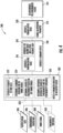
- the controller 200 may include one or more processor(s) 206 and associated memory device(s) 208 configured to perform a variety of computer-implemented functions (e.g., performing the methods, steps, calculations and the like and storing relevant data as disclosed herein).
- the controller 200 may also include a communications module 210 to facilitate communications between the controller 200 and the various components of the wind turbines 100.
- the communications module 210 may include a sensor interface 212 (e.g., one or more analog-to-digital converters) to permit signals transmitted from one or more sensors 156, 158, 162 to be converted into signals that can be understood and processed by the processors 206.
- the sensors 156, 158, 162 may be communicatively coupled to the communications module 210 using any suitable means.
- the sensors 156, 158, 162 are coupled to the sensor interface 212 via a wired connection.
- the sensors 156, 158, 162 may be coupled to the sensor interface 212 via a wireless connection, such as by using any suitable wireless communications protocol known in the art.
- the communications module 210 may also be operably coupled to an operating state control module 214 configured to change at least one wind turbine operating state/operating parameter.
- the term "processor” refers not only to integrated circuits referred to in the art as being included in a computer, but also refers to a controller, a microcontroller, a microcomputer, a programmable logic controller (PLC), an application specific integrated circuit, and other programmable circuits.
- the memory device(s) 208 may generally comprise memory element(s) including, but not limited to, computer readable medium (e.g., random access memory (RAM)), computer readable non-volatile medium (e.g., a flash memory), a floppy disk, a compact disc-read only memory (CD-ROM), a magneto-optical disk (MOD), a digital versatile disc (DVD) and/or other suitable memory elements.
- RAM random access memory
- CD-ROM compact disc-read only memory
- MOD magneto-optical disk
- DVD digital versatile disc
- Such memory device(s) 208 may generally be configured to store suitable computer-readable instructions that, when implemented by the processor(s) 206, configure the controller 200 to perform various functions including, but not limited to, detecting at least one parameter indicative of an output flicker, generating a command offset for a wind turbine, and changing an operating parameter of the wind turbine based on the command offset in order to de-synchronize the synchronized flicker in the output signals of the wind turbines, as described herein, as well as various other suitable computer-implemented functions.
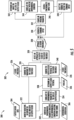
- the farm controller 202 of the system 300 is configured to detect at least one parameter 302 of the wind farm 152 indicative of an output flicker occurring in the power grid and generated by at least two of the wind turbines 100.
- the parameter(s) 302 may be indicated by output sensor data 304, the environmental sensor data 306, and/or a timing signal 308.
- the parameter(s) 302 may include measurements of the flicker in the output of the wind farm 152 as indicated by variations in current and/or voltage, which may be indicative of synchronized flicker.
- the parameter(s) 302 may include data indicative of an environmental condition affecting the wind turbines 100.
- the parameter(s) 302 may include rotor positions of the rotors 108 of the wind turbines 100 as indicated by the timing signal 308. Additionally, in an embodiment, the parameter(s) 302 may be a learned wind turbine behavior wherein historical environmental conditions that resulted in flicker may be correlated to determine an output flicker potential corresponding to a weather forecast. In yet a further embodiment, the parameter(s) 302 may correspond to an operational state of the wind farm. For example, in an embodiment, the presence of synchronized flicker may be presumed whenever the wind farm 152 is in operation and, therefore, the control logic of the system 300 may be utilized to de-synchronize the output of each wind turbine 100 of the wind farm 152.
- the flicker generated by the wind farm 152 is the result of the synchronization of flicker present in the output of at least a portion of the plurality of wind turbines 100 of the wind farm 152.
- FIG. 6 depicts an embodiment wherein the output signal of a first wind turbine 164, a second wind turbine 166, and a third wind turbine 168 may be characterized by frequency and amplitude variations in current/voltage, which may be synchronized.
- the resultant output of the wind farm 152 may reflect the combined, synchronized flicker of the wind turbines 100, as indicated by the plot 170.
- plot 170 may reflect flicker in the output of the wind farm 152 as seen by the power grid, and which may be delivered to a power grid consumer.
- the system 300 may be employed to change an operating parameter of at least one wind turbine 100 in order to de-synchronize the synchronized flicker in the output signals.
- the output signals of the first, second, and third wind turbines 164, 166, 168 may be characterized by frequency and amplitude variations in current/voltage which are de-synchronized relative to one another as depicted in FIG. 7 .
- the combination of the de-synchronized output signals may result in an output signal of the wind farm 152 having an absence of flicker as depicted by plot 172.
- the frequency and amplitude variations (e.g., flicker) in the output signal of a wind turbine 100 may be essentially masked by the frequency and amplitude variations in the output signal of another wind turbine 100 of the wind farm 152. Therefore, while flicker may, in an embodiment, be detectable in the outputs of the individual wind turbines 100, the combination of the de-synchronized outputs, as reflected by the output of the wind farm 152, may be a stable/constant output as perceived by a power grid consumer.
- the farm controller 202 of the system 300 is configured to generate a command offset 310 for at least one wind turbine 100 upon detecting the parameter(s) 302 indicative of the synchronized flicker of the outputs of at least two wind turbines 100.
- the command offset 310 facilitates the de-synchronization of the synchronized flicker in order to develop a wind farm 152 output which does not demonstrate the characteristics of flicker.
- the command offset is employed by the system 300 to change an operating parameter of the wind turbine(s) 100 so as to de-synchronize the synchronized flicker in the output signals of the at least two wind turbines at 314.
- changing the operating parameter of the wind turbine(s) 100 based on the command offset 310 may include changing an operating parameter corresponding to a generator torque, power output, rotors speed, and/or mechanical loading of the wind turbine(s) 100.
- the command offset may be merged with a setpoint command for the wind turbine(s) 100 to generate a modified setpoint command.
- the modified setpoint command may, in an embodiment, be transmitted to the wind turbine(s) 100 in order to adjust the operating state of the wind turbine(s) 100.
- the system 300 may follow the transmission of the modified setpoint command with the transmission of an unmodified setpoint command thereby returning the wind turbine(s) 100 to the original operating state but without the previously detected synchronized flicker.
- the torque set point of the generator may be temporarily increased, resulting in an alteration of the frequency and/or amplitude of variations in the output current/voltage of the wind turbine(s) 100, before returning to a previous established optimal torque setpoint for the given operating state of the wind turbine(s) 100.
- generating the command offset 310 includes the generation of a random biasing value 316 by the farm controller 202.
- the random biasing value 316 may be a random value introduced into a control logic of the wind turbine(s) 100 to temporarily bias a setpoint of the wind turbine(s) 100.
- the farm controller 202 may be configured to introduce the biasing value 316 into a speed feedback loop of the turbine controller(s) 204 of the wind turbine(s) 100 to develop a variable rotor speed 320 for the wind turbine(s) 100.
- the random biasing value 316 may include different variables introduced to different wind turbines 100 of the wind farm 152.
- the random biasing value 316 may be a single value introduced to a random selection of wind turbines 100 of the wind farm 152 at a first instant, and a different random selection of wind turbines 100 at a second instant.
- the farm controller 202 of the system 300 may be configured to receive output sensor data 304 from the output sensor(s) 162. Accordingly, the output sensor(s) 162 may, at 322, be utilized to monitor the frequency and amplitude of variations in current and/or voltage of the output of the wind farm 152 at the POI. In an embodiment, the frequency and/or amplitude of the variations in the output of the wind farm 152 may be indicative of the synchronization of the flicker present in the output of various wind turbines 100 of the wind farm 152. As depicted at 324, in an embodiment, the farm controller 202 may compare the monitored variations in current and/or voltage to a flicker threshold 326.
- the farm controller 202 may, at 328, detect an approach of the output of the output sensor(s) 162 to the flicker threshold 326 for the wind farm 152. In an embodiment wherein the farm controller 202 determines, at 330, a level of flicker which approaches or exceeds the flicker threshold 326, the farm controller 202 may generate the command offset 310.
- detecting the parameter(s) 302 indicative of output flicker may include monitoring environmental sensor data 306.
- the environmental sensor data 306 may be at least one environmental parameter 332 indicative of an environmental condition affecting the wind farm 152.
- the farm controller 202 may, at 334, correlate the environmental parameter(s) 332 to an indication of a level of output flicker.
- the farm controller 202 may, in an embodiment, correlate the environmental parameter(s) 332 to the level of output flicker detected by the output sensor(s) 162 at the monitored environmental condition.
- the correlation of the environmental conditions to the level of output flicker may be accomplished over a specified period in order to establish a historical data set of correlations based on the observed relationship between the environmental conditions and the resultant level of output flicker.
- the farm controller 202 of the system 300 may be configured to receive an environmental condition forecast 336. Based at least in part on the environmental condition forecast 336 and the correlation between the environmental parameter(s) 332/level of output flicker correlation, the farm controller 202 may determine an output flicker potential 338. It should be appreciated that the output flicker potential 338 may represent the degree of synchronized flicker which may be anticipated when the wind farm is affected by the forecasted environmental conditions.
- the farm controller 202 may be configured to compare the output flicker potential 338 to the flicker threshold 326 in order to detect, at 328, an approach of the flicker potential 338 to the flicker threshold 326.
- the farm controller 202 may generate the command offset 310.
- the farm controller 202 may receive a weather forecast and may determine the anticipated level of output flicker under the forecast conditions. This anticipated level may, in an embodiment, be compared to the flicker threshold 326.
- the farm controller 202 may prospectively generate the command offset 310 so as to preclude the development of an unacceptable level of output flicker in the output of the wind farm 152. Accordingly, it should be appreciated that the farm controller 202 may, in an embodiment generate the command offset 310 when the output flicker potential 338 and/or the output of the output sensor(s) 162 approaches or exceeds the flicker threshold 326 for the wind farm 152.
- the farm controller 202 of the system 300 may be configured to execute a feedback loop wherein the de-synchronization efficacy of the various wind turbines 100 of the wind farm 152 may be determined for various environmental conditions. Accordingly, the farm controller 202 may determine an impact 342 on the level of output flicker resulting from the changing of the operating parameter, at 312, of the wind turbine(s) 100 based on the command offset 310. As depicted at 344, the farm controller 202 may correlate the impact 342 with the environmental condition affecting the wind turbine 152 as indicated by the environmental parameter(s) 332. In an embodiment, the farm controller 202 may assign a synchronicity-impact score 346 to the wind turbine(s) 100 based on the computed correlation for the detected environmental condition.
- the farm controller 202 may, at 348, select the wind turbine(s) 100 from the plurality of wind turbines 100 to receive the command offset 310.
- the feedback loop may be executed each time the command offset 310 is generated in response to the detection of the parameter(s) 302 indicative of output flicker, over a specified number of command cycles, and/or a specified period. Accordingly, a historical data set of correlations between the environmental parameter(s) 332 (e.g., weather conditions) and the de-synchronization efficacy of the wind turbine(s) 100.
- the farm controller 202 may utilize the historical data set, at least in part, to select the wind turbine(s) 100 from the plurality of wind turbines 100 which may be most effective at de-synchronizing the synchronized flicker output either prospectively or reactively.
- the detection of the parameter(s) 302 indicative of the output flicker may be based, at least in part, on the rotor positions of at least two wind turbines 100.
- the farm controller 202 of the system 300 may be configured to receive a timing signal 308 from at least two wind turbines 100 of the wind farm 152.
- the timing signal 308 may be indicative of the rotor position for the rotors 108 for each of the wind turbines 100.
- the rotor position may indicate that a rotor blade 112 of each respective rotor 108 may be passing the tower 102 at the same instant, thereby indicating that the rotation of the respective rotors 108 may be synchronized.
- the farm controller 202 may, in an embodiment, determine a degree of synchronicity 350 amongst the wind turbines 100.
- the at least two wind turbines 100 may be at least a first sub-grouping 360 of wind turbines 100 and a second sub-grouping 362 of wind turbines 100.
- the timing signals 308 of the individual wind turbines 100 of the respective sub-groupings 360, 362 may be consolidated into a single timing signal 308 for each of the sub-groupings 360, 362.
- the timing signals 308 received by the farm controller 202 may correspond to a consolidated timing signal for the first sub-grouping 360 and a consolidated timing signal for the second sub-grouping 362.
- determining the degree of synchronicity 350 may include establishing a plurality of time slices 352 with the farm controller 202. The farm controller 202 may then determine a standard deviation 354 for the timing signal 308 across the time slices. The standard deviation 354 may be indicative of the degree of synchronicity 350 amongst the wind turbines 100. It should be appreciated that the lower the standard deviation 354, the greater the degree of synchronicity 350 amongst the wind turbines 100, with the opposite being also true.
- the farm controller 202 may, in an embodiment, determine, at 356, a difference between the degree of synchronicity 350 and a synchronicity threshold 358.
- the synchronicity threshold 358 may correspond to the flicker threshold 326 such that an approach to the synchronicity threshold 358 may indicate an approach of the output flicker in the output of the wind farm 152 to the flicker threshold 326. It should be appreciated that the utilization of the degree of synchronicity 350 to detect an approach of the level of flicker to the flicker threshold 326 may preclude the requirement to monitor the output of the wind farm 152 and/or the environmental parameter(s) 332, or may be employed in conjunction with the monitoring of the output and/or the environmental parameter(s) 332.
Landscapes
- Engineering & Computer Science (AREA)
- Life Sciences & Earth Sciences (AREA)
- Sustainable Development (AREA)
- Sustainable Energy (AREA)
- Chemical & Material Sciences (AREA)
- Combustion & Propulsion (AREA)
- Mechanical Engineering (AREA)
- General Engineering & Computer Science (AREA)
- Power Engineering (AREA)
- Physics & Mathematics (AREA)
- Nonlinear Science (AREA)
- Wind Motors (AREA)
Claims (12)
- Verfahren zur Steuerung des Ausgangsflimmerns eines Windparks (152), der an ein Stromnetz angeschlossen ist, wobei der Windpark (152) eine Vielzahl von Windturbinen (100) umfasst, wobei das Verfahren Folgendes umfasst:Erfassen, mit einem Steuergerät (202), mindestens eines Parameters des Windparks (152), der ein Ausgangsflimmern anzeigt, das aus einem synchronisierten Flimmern von mindestens zwei Windturbinen (100) der Vielzahl von Windturbinen (100) resultiert;beim Erfassen des mindestens einen Parameters, Erzeugen eines Befehlsoffsets (310) für mindestens eine Windturbine (100) der mindestens zwei Windturbinen (100), wobei das Erzeugen des Befehlsoffsets (310) das Erzeugen eines zufälligen Verzerrungswertes (316) umfasst; undÄndern eines Betriebsparameters der mindestens einen Windkraftanlage (100) auf der Grundlage des Befehlsoffsets (310), um das synchronisierte Flimmern in den Ausgangssignalen der mindestens zwei Windkraftanlagen (100) zu desynchronisieren,wobei der zufällige Verzerrungswert (316) in eine Drehzahlrückkopplungsschleife eines Turbinenreglers (200) eingeführt wird, um eine variable Rotordrehzahl für die mindestens eine Windturbine (100) zu entwickeln.
- . Verfahren nach Anspruch 1, wobei der Windpark (152) ferner mindestens einen Ausgangssensor (162) umfasst, der betriebsmäßig mit dem Steuergerät (202) an einem Verbindungspunkt mit dem Stromnetz gekoppelt ist, und wobei das Erfassen des mindestens einen Parameters, der ein Ausgangsflimmern anzeigt, ferner umfasst:Überwachen, über den mindestens einen Ausgangssensor (162), einer Frequenz und Amplitude von Schwankungen des Stroms oder der Spannung eines Ausgangs des Windparks (152) am Verbindungspunkt mit dem Stromnetz, wobei die Frequenz und Amplitude der Schwankungen das synchronisierte Flimmern anzeigen; undErkennen einer Annäherung des Ausgangs an eine Flimmerschwelle für den Windpark (152) mit dem Steuergerät (202).
- . Verfahren nach Anspruch 2, wobei der Windpark (152) ferner mindestens einen Umgebungssensor (158) umfasst, der betriebsfähig mit dem Steuergerät (202) gekoppelt ist, und wobei das Erfassen des mindestens einen Parameters, der das Ausgangsflimmern anzeigt, ferner umfasst:Überwachen, über den mindestens einen Umweltsensor (158), mindestens eines Umweltparameters, der einen Umweltzustand anzeigt, der den Windpark (152) beeinflusst; undKorrelieren des mindestens einen Umgebungsparameters mit dem Steuergerät (202) mit einem Niveau des Ausgangsflimmerns, wie es von dem mindestens einen Ausgangssensor (162) bei der überwachten Umgebungsbedingung erfasst wird.
- . Verfahren nach Anspruch 3, weiter umfassend:
Bestimmen, mit dem Steuergerät (202), eines Ausgangsflimmerpotentials für den Windpark (152), das zumindest teilweise auf der Korrelation und einer vorhergesagten Umweltbedingung basiert. - . Verfahren nach Anspruch 4, wobei das Erzeugen des Befehlsoffsets (310) ferner das Erzeugen des Befehlsoffsets (310) umfasst,
wenn mindestens eines von dem Ausgangsflimmerpotenzial oder dem Ausgang des Windparks (152) sich dem Flimmerschwellenwert für den Windpark (152) nähert oder diesen überschreitet. - . Verfahren nach Anspruch 3, 4 oder 5, weiter umfassend:Bestimmen einer Auswirkung auf das Niveau des Ausgangsflimmerns, die sich aus der Änderung des Betriebsparameters der mindestens einen Windturbine (100) ergibt, basierend auf dem Befehlsoffset (310);Korrelieren, mit dem Steuergerät (202), der Auswirkung mit den Umweltbedingungen, die auf den Windpark (152) einwirken;Zuordnen einer Synchronitätsauswirkungsbewertung (346) zu der mindestens einen Windturbine (100) auf der Grundlage der berechneten Korrelation für den erfassten Umgebungszustand; undAuswählen der mindestens einen Windturbine (100) aus der Vielzahl von Windturbinen (100), um den Befehlsoffset (310) zu erhalten, zumindest teilweise basierend auf der Synchronitätsauswirkungsbewertung (346).
- . Verfahren nach einem der vorhergehenden Ansprüche, wobei das Erfassen des mindestens einen Parameters, der das Ausgangsflimmern anzeigt, ferner umfasst:Empfangen eines Zeitsignals (308) von den mindestens zwei Windturbinen mit dem Steuergerät (202), wobei das Zeitsignal (308) eine Rotorposition für jede der Windturbinen anzeigt;Bestimmen, mit dem Steuergerät (202), eines Synchronitätsgrades (350) zwischen den mindestens zwei Windturbinen (100) der Vielzahl von Windturbinen (100), basierend auf den jeweiligen Zeitsignalen (308); undBestimmen einer Differenz zwischen dem Synchronitätsgrad (350) und einem Synchronitätsschwellenwert, der einem Schwellenwert für synchronisiertes Flimmern entspricht, mit dem Steuergerät (202).
- . Verfahren nach Anspruch 7, wobei das Bestimmen des Synchronitätsgrades (350) zwischen den mindestens zwei Windturbinen (100) der Vielzahl von Windturbinen (100) weiterhin umfasst:Erstellen einer Vielzahl von Zeitscheiben mit dem Steuergerät (202); undBestimmen, mit dem Steuergerät (202), einer Standardabweichung (354) für die Zeitsignale (308) über die Zeitscheiben, wobei die Standardabweichung (354) für die Zeitsignale (308) den Synchronitätsgrad (350) zwischen der Vielzahl von Windturbinen anzeigt.
- . Verfahren nach Anspruch 7 oder 8, wobei die mindestens zwei Windturbinen (100) der Vielzahl von Windturbinen (100) mindestens eine erste Untergruppe (360) von Windturbinen (100) und eine zweite Untergruppe (362) von Windturbinen (100) umfassen, und wobei die jeweiligen Zeitsteuerungssignale (308) eine kombinierte Zeitsteuerung der Windturbinen (100), die die erste Untergruppe (360) umfassen, und eine kombinierte Zeitsteuerung der Windturbinen (100), die die zweite Untergruppe (362) von Windturbinen (100) umfassen, anzeigen.
- . Verfahren nach einem der vorhergehenden Ansprüche, wobei das Ändern des Betriebsparameters der mindestens einen Windturbine (100) auf der Grundlage des Befehlsoffsets (310) ferner das Ändern des Betriebsparameters umfasst, der mindestens einem der folgenden Parameter entspricht: Generatormoment, Leistungsabgabe, Rotordrehzahl oder mechanische Belastung der Windturbine.
- . System (300) zum Steuern eines Ausgangsflimmerns, das von einem Windpark (152) erzeugt wird, wobei das System umfasst:eine Vielzahl von Windturbinen (100), die mit einem elektrischen Netz verbunden sind; undeine Windparksteuerung (202), die kommunikativ mit der Vielzahl von Windturbinen (100) und mit dem Stromnetz verbunden ist, wobei die Windparksteuerung (202) mindestens einen Prozessor umfasst, der so konfiguriert ist, dass er eine Mehrzahl von Operationen durchführt, wobei die Mehrzahl von Operationen Folgendes umfasst:Erfassen mindestens eines Parameters des Windparks (152), der auf ein synchronisiertes Flimmern von mindestens zwei Windturbinen (100) der Vielzahl von Windturbinen (100) hinweist, wobei das synchronisierte Flimmern im Stromnetz auftritt,beim Erfassen des mindestens einen Parameters, Erzeugen eines Befehlsoffsets (310) für mindestens eine Windturbine (100) der mindestens zwei Windturbinen, wobei das Erzeugen des Befehlsoffsets (310) das Erzeugen eines zufälligen Verzerrungswertes (316) umfasst, undÄndern eines Betriebsparameters der mindestens einen Windkraftanlage (100) auf der Grundlage des Befehlsoffsets (310), um das synchronisierte Flimmern in den Ausgangssignalen der mindestens zwei Windkraftanlagen zu desynchronisieren, wobei der zufällige Verzerrungswert (316) in eine Drehzahlrückkopplungsschleife eines Turbinenreglers (200) eingeführt wird, um eine variable Rotordrehzahl für die mindestens eine Windturbine (100) zu entwickeln.
- . System (300) nach Anspruch 11, wobei der Windpark (152) ferner mindestens einen Ausgangssensor (162) umfasst, der betriebsmäßig mit der Windparksteuerung (202) an einem Verbindungspunkt mit dem Stromnetz gekoppelt ist, und wobei die Operation der Erfassung des mindestens einen Parameters, der das Ausgangsflimmern anzeigt, ferner umfasst:Überwachen, über den mindestens einen Ausgangssensor (162), einer Frequenz und Amplitude von Schwankungen des Stroms oder der Spannung eines Ausgangs des Windparks (152) am Verbindungspunkt mit dem Stromnetz, wobei die Frequenz und Amplitude der Schwankungen das synchronisierte Flimmern anzeigen; undErkennen einer Annäherung der Leistung an eine Flimmerschwelle für den Windpark (152) mit der Windparksteuerung (202).
Applications Claiming Priority (1)
| Application Number | Priority Date | Filing Date | Title |
|---|---|---|---|
| US16/998,034 US11530685B2 (en) | 2020-08-20 | 2020-08-20 | System and method for managing output flicker generated by a wind farm |
Publications (2)
| Publication Number | Publication Date |
|---|---|
| EP3961845A1 EP3961845A1 (de) | 2022-03-02 |
| EP3961845B1 true EP3961845B1 (de) | 2024-12-18 |
Family
ID=77398494
Family Applications (1)
| Application Number | Title | Priority Date | Filing Date |
|---|---|---|---|
| EP21191952.7A Active EP3961845B1 (de) | 2020-08-20 | 2021-08-18 | System und verfahren zur verwaltung eines von einem windpark erzeugten ausgabeflackerns |
Country Status (5)
| Country | Link |
|---|---|
| US (1) | US11530685B2 (de) |
| EP (1) | EP3961845B1 (de) |
| CN (1) | CN114076066B (de) |
| DK (1) | DK3961845T3 (de) |
| ES (1) | ES3014993T3 (de) |
Family Cites Families (18)
| Publication number | Priority date | Publication date | Assignee | Title |
|---|---|---|---|---|
| US6600240B2 (en) | 1997-08-08 | 2003-07-29 | General Electric Company | Variable speed wind turbine generator |
| NO20001641L (no) | 2000-03-29 | 2001-10-01 | Abb Research Ltd | Vindkraftanlegg |
| US6924565B2 (en) | 2003-08-18 | 2005-08-02 | General Electric Company | Continuous reactive power support for wind turbine generators |
| US7119452B2 (en) | 2003-09-03 | 2006-10-10 | General Electric Company | Voltage control for wind generators |
| DE102004048341A1 (de) * | 2004-10-01 | 2006-04-13 | Repower Systems Ag | Windpark mit robuster Blindleistungsregelung und Verfahren zum Betrieb |
| CN101267117B (zh) * | 2008-04-30 | 2010-06-09 | 北京清能华福风电技术有限公司 | 一种变速恒频双馈风力发电系统及其并网控制方法 |
| AU2009265720B2 (en) | 2008-06-30 | 2011-12-08 | Vestas Wind Systems A/S | A method of controlling a wind power plant |
| US7804184B2 (en) | 2009-01-23 | 2010-09-28 | General Electric Company | System and method for control of a grid connected power generating system |
| CN102374118B (zh) | 2010-08-11 | 2013-06-12 | 华锐风电科技(江苏)有限公司 | 风力发电机组的功率控制方法 |
| TWI445276B (zh) | 2011-10-04 | 2014-07-11 | Iner Aec Executive Yuan | 一種整合自動電壓調整器之控制系統和方法 |
| CN103061972A (zh) * | 2011-10-20 | 2013-04-24 | 华锐风电科技(集团)股份有限公司 | 风力发电机组的功率控制方法及系统 |
| US9450415B2 (en) | 2012-08-31 | 2016-09-20 | General Electric Company | System and method for controlling a dual-fed induction generator in response to high-voltage grid events |
| US9780709B2 (en) * | 2014-09-03 | 2017-10-03 | General Electric Company | System and method for optimizing wind turbine operation |
| US9458830B2 (en) | 2014-09-05 | 2016-10-04 | General Electric Company | System and method for improving reactive current response time in a wind turbine |
| US9831810B2 (en) | 2015-03-10 | 2017-11-28 | General Electric Company | System and method for improved reactive power speed-of-response for a wind farm |
| EP3116089B1 (de) * | 2015-07-07 | 2020-02-26 | Siemens Gamesa Renewable Energy A/S | Windturbinenbetrieb basierend auf der frequenz eines von einem umrichter für die windturbine bereitgestellten wechselstromausgangsspannungssignals |
| US10491146B2 (en) | 2018-03-30 | 2019-11-26 | General Electric Company | System and method for compensating for generator-induced flicker in a wind turbine |
| DE102018114935A1 (de) * | 2018-06-21 | 2019-12-24 | Wobben Properties Gmbh | Leistungsreduzierter Betrieb einer Windenergieanlage |
-
2020
- 2020-08-20 US US16/998,034 patent/US11530685B2/en active Active
-
2021
- 2021-08-18 EP EP21191952.7A patent/EP3961845B1/de active Active
- 2021-08-18 ES ES21191952T patent/ES3014993T3/es active Active
- 2021-08-18 DK DK21191952.7T patent/DK3961845T3/da active
- 2021-08-20 CN CN202110960806.5A patent/CN114076066B/zh active Active
Also Published As
| Publication number | Publication date |
|---|---|
| EP3961845A1 (de) | 2022-03-02 |
| CN114076066B (zh) | 2025-12-12 |
| ES3014993T3 (en) | 2025-04-28 |
| US20220056883A1 (en) | 2022-02-24 |
| US11530685B2 (en) | 2022-12-20 |
| CN114076066A (zh) | 2022-02-22 |
| DK3961845T3 (da) | 2025-03-24 |
Similar Documents
| Publication | Publication Date | Title |
|---|---|---|
| US10107261B2 (en) | System and method for reducing oscillation loads of wind turbine | |
| US9014861B2 (en) | Method and system for noise-controlled operation of a wind turbine | |
| US8249852B2 (en) | Condition monitoring of windturbines | |
| CN101568721B (zh) | 风力发电装置、风力发电系统以及风力发电装置的发电控制方法 | |
| EP2369432B1 (de) | Test System zur Windturbinenbetriebsoptimierung | |
| CN103206344B (zh) | 用于操作风力涡轮机的方法 | |
| US11242841B2 (en) | System and method for controlling a wind turbine based on a collective pitch-offset | |
| DK2541055T3 (en) | System and methods for controlling the amplitude modulation of the noise generated by wind turbines | |
| EP2952860B1 (de) | System und verfahren zum schutz von rotierenden maschinen | |
| US9291154B2 (en) | Methods and systems for use in monitoring a tachometer | |
| US10156224B2 (en) | System and method for controlling a wind turbine | |
| EP3723230B1 (de) | System und verfahren zur abschätzung der stärke eines netzes | |
| US12410780B2 (en) | System and method for controlling a wind turbine | |
| EP3961845B1 (de) | System und verfahren zur verwaltung eines von einem windpark erzeugten ausgabeflackerns | |
| EP3124789B1 (de) | Windturbinensteuerung mit sekundärer steuerung zur einstellung der eingangswerte der windgeschwindigkeit und/oder -richtung |
Legal Events
| Date | Code | Title | Description |
|---|---|---|---|
| PUAI | Public reference made under article 153(3) epc to a published international application that has entered the european phase |
Free format text: ORIGINAL CODE: 0009012 |
|
| STAA | Information on the status of an ep patent application or granted ep patent |
Free format text: STATUS: THE APPLICATION HAS BEEN PUBLISHED |
|
| AK | Designated contracting states |
Kind code of ref document: A1 Designated state(s): AL AT BE BG CH CY CZ DE DK EE ES FI FR GB GR HR HU IE IS IT LI LT LU LV MC MK MT NL NO PL PT RO RS SE SI SK SM TR |
|
| STAA | Information on the status of an ep patent application or granted ep patent |
Free format text: STATUS: REQUEST FOR EXAMINATION WAS MADE |
|
| 17P | Request for examination filed |
Effective date: 20220706 |
|
| RBV | Designated contracting states (corrected) |
Designated state(s): AL AT BE BG CH CY CZ DE DK EE ES FI FR GB GR HR HU IE IS IT LI LT LU LV MC MK MT NL NO PL PT RO RS SE SI SK SM TR |
|
| P01 | Opt-out of the competence of the unified patent court (upc) registered |
Effective date: 20230530 |
|
| RAP1 | Party data changed (applicant data changed or rights of an application transferred) |
Owner name: GENERAL ELECTRIC RENOVABLES ESPANA, S.L. |
|
| GRAP | Despatch of communication of intention to grant a patent |
Free format text: ORIGINAL CODE: EPIDOSNIGR1 |
|
| STAA | Information on the status of an ep patent application or granted ep patent |
Free format text: STATUS: GRANT OF PATENT IS INTENDED |
|
| INTG | Intention to grant announced |
Effective date: 20240516 |
|
| GRAJ | Information related to disapproval of communication of intention to grant by the applicant or resumption of examination proceedings by the epo deleted |
Free format text: ORIGINAL CODE: EPIDOSDIGR1 |
|
| STAA | Information on the status of an ep patent application or granted ep patent |
Free format text: STATUS: REQUEST FOR EXAMINATION WAS MADE |
|
| GRAP | Despatch of communication of intention to grant a patent |
Free format text: ORIGINAL CODE: EPIDOSNIGR1 |
|
| STAA | Information on the status of an ep patent application or granted ep patent |
Free format text: STATUS: GRANT OF PATENT IS INTENDED |
|
| INTC | Intention to grant announced (deleted) | ||
| INTG | Intention to grant announced |
Effective date: 20240731 |
|
| GRAS | Grant fee paid |
Free format text: ORIGINAL CODE: EPIDOSNIGR3 |
|
| GRAA | (expected) grant |
Free format text: ORIGINAL CODE: 0009210 |
|
| STAA | Information on the status of an ep patent application or granted ep patent |
Free format text: STATUS: THE PATENT HAS BEEN GRANTED |
|
| AK | Designated contracting states |
Kind code of ref document: B1 Designated state(s): AL AT BE BG CH CY CZ DE DK EE ES FI FR GB GR HR HU IE IS IT LI LT LU LV MC MK MT NL NO PL PT RO RS SE SI SK SM TR |
|
| REG | Reference to a national code |
Ref country code: CH Ref legal event code: EP |
|
| REG | Reference to a national code |
Ref country code: DE Ref legal event code: R096 Ref document number: 602021023476 Country of ref document: DE |
|
| REG | Reference to a national code |
Ref country code: IE Ref legal event code: FG4D |
|
| REG | Reference to a national code |
Ref country code: DK Ref legal event code: T3 Effective date: 20250318 |
|
| REG | Reference to a national code |
Ref country code: LT Ref legal event code: MG9D |
|
| PG25 | Lapsed in a contracting state [announced via postgrant information from national office to epo] |
Ref country code: HR Free format text: LAPSE BECAUSE OF FAILURE TO SUBMIT A TRANSLATION OF THE DESCRIPTION OR TO PAY THE FEE WITHIN THE PRESCRIBED TIME-LIMIT Effective date: 20241218 |
|
| PG25 | Lapsed in a contracting state [announced via postgrant information from national office to epo] |
Ref country code: FI Free format text: LAPSE BECAUSE OF FAILURE TO SUBMIT A TRANSLATION OF THE DESCRIPTION OR TO PAY THE FEE WITHIN THE PRESCRIBED TIME-LIMIT Effective date: 20241218 |
|
| PG25 | Lapsed in a contracting state [announced via postgrant information from national office to epo] |
Ref country code: BG Free format text: LAPSE BECAUSE OF FAILURE TO SUBMIT A TRANSLATION OF THE DESCRIPTION OR TO PAY THE FEE WITHIN THE PRESCRIBED TIME-LIMIT Effective date: 20241218 |
|
| PG25 | Lapsed in a contracting state [announced via postgrant information from national office to epo] |
Ref country code: NO Free format text: LAPSE BECAUSE OF FAILURE TO SUBMIT A TRANSLATION OF THE DESCRIPTION OR TO PAY THE FEE WITHIN THE PRESCRIBED TIME-LIMIT Effective date: 20250318 |
|
| REG | Reference to a national code |
Ref country code: NL Ref legal event code: MP Effective date: 20241218 |
|
| PG25 | Lapsed in a contracting state [announced via postgrant information from national office to epo] |
Ref country code: LV Free format text: LAPSE BECAUSE OF FAILURE TO SUBMIT A TRANSLATION OF THE DESCRIPTION OR TO PAY THE FEE WITHIN THE PRESCRIBED TIME-LIMIT Effective date: 20241218 Ref country code: GR Free format text: LAPSE BECAUSE OF FAILURE TO SUBMIT A TRANSLATION OF THE DESCRIPTION OR TO PAY THE FEE WITHIN THE PRESCRIBED TIME-LIMIT Effective date: 20250319 |
|
| PG25 | Lapsed in a contracting state [announced via postgrant information from national office to epo] |
Ref country code: RS Free format text: LAPSE BECAUSE OF FAILURE TO SUBMIT A TRANSLATION OF THE DESCRIPTION OR TO PAY THE FEE WITHIN THE PRESCRIBED TIME-LIMIT Effective date: 20250318 |
|
| PG25 | Lapsed in a contracting state [announced via postgrant information from national office to epo] |
Ref country code: NL Free format text: LAPSE BECAUSE OF FAILURE TO SUBMIT A TRANSLATION OF THE DESCRIPTION OR TO PAY THE FEE WITHIN THE PRESCRIBED TIME-LIMIT Effective date: 20241218 |
|
| REG | Reference to a national code |
Ref country code: AT Ref legal event code: MK05 Ref document number: 1753035 Country of ref document: AT Kind code of ref document: T Effective date: 20241218 |
|
| PG25 | Lapsed in a contracting state [announced via postgrant information from national office to epo] |
Ref country code: SM Free format text: LAPSE BECAUSE OF FAILURE TO SUBMIT A TRANSLATION OF THE DESCRIPTION OR TO PAY THE FEE WITHIN THE PRESCRIBED TIME-LIMIT Effective date: 20241218 |
|
| PG25 | Lapsed in a contracting state [announced via postgrant information from national office to epo] |
Ref country code: PL Free format text: LAPSE BECAUSE OF FAILURE TO SUBMIT A TRANSLATION OF THE DESCRIPTION OR TO PAY THE FEE WITHIN THE PRESCRIBED TIME-LIMIT Effective date: 20241218 |
|
| PG25 | Lapsed in a contracting state [announced via postgrant information from national office to epo] |
Ref country code: IS Free format text: LAPSE BECAUSE OF FAILURE TO SUBMIT A TRANSLATION OF THE DESCRIPTION OR TO PAY THE FEE WITHIN THE PRESCRIBED TIME-LIMIT Effective date: 20250418 |
|
| PG25 | Lapsed in a contracting state [announced via postgrant information from national office to epo] |
Ref country code: PT Free format text: LAPSE BECAUSE OF FAILURE TO SUBMIT A TRANSLATION OF THE DESCRIPTION OR TO PAY THE FEE WITHIN THE PRESCRIBED TIME-LIMIT Effective date: 20250421 |
|
| PG25 | Lapsed in a contracting state [announced via postgrant information from national office to epo] |
Ref country code: EE Free format text: LAPSE BECAUSE OF FAILURE TO SUBMIT A TRANSLATION OF THE DESCRIPTION OR TO PAY THE FEE WITHIN THE PRESCRIBED TIME-LIMIT Effective date: 20241218 |
|
| PG25 | Lapsed in a contracting state [announced via postgrant information from national office to epo] |
Ref country code: AT Free format text: LAPSE BECAUSE OF FAILURE TO SUBMIT A TRANSLATION OF THE DESCRIPTION OR TO PAY THE FEE WITHIN THE PRESCRIBED TIME-LIMIT Effective date: 20241218 Ref country code: RO Free format text: LAPSE BECAUSE OF FAILURE TO SUBMIT A TRANSLATION OF THE DESCRIPTION OR TO PAY THE FEE WITHIN THE PRESCRIBED TIME-LIMIT Effective date: 20241218 |
|
| PG25 | Lapsed in a contracting state [announced via postgrant information from national office to epo] |
Ref country code: SK Free format text: LAPSE BECAUSE OF FAILURE TO SUBMIT A TRANSLATION OF THE DESCRIPTION OR TO PAY THE FEE WITHIN THE PRESCRIBED TIME-LIMIT Effective date: 20241218 |
|
| PG25 | Lapsed in a contracting state [announced via postgrant information from national office to epo] |
Ref country code: CZ Free format text: LAPSE BECAUSE OF FAILURE TO SUBMIT A TRANSLATION OF THE DESCRIPTION OR TO PAY THE FEE WITHIN THE PRESCRIBED TIME-LIMIT Effective date: 20241218 |
|
| PG25 | Lapsed in a contracting state [announced via postgrant information from national office to epo] |
Ref country code: IT Free format text: LAPSE BECAUSE OF FAILURE TO SUBMIT A TRANSLATION OF THE DESCRIPTION OR TO PAY THE FEE WITHIN THE PRESCRIBED TIME-LIMIT Effective date: 20241218 |
|
| PG25 | Lapsed in a contracting state [announced via postgrant information from national office to epo] |
Ref country code: SE Free format text: LAPSE BECAUSE OF FAILURE TO SUBMIT A TRANSLATION OF THE DESCRIPTION OR TO PAY THE FEE WITHIN THE PRESCRIBED TIME-LIMIT Effective date: 20241218 |
|
| REG | Reference to a national code |
Ref country code: DE Ref legal event code: R097 Ref document number: 602021023476 Country of ref document: DE |
|
| PGFP | Annual fee paid to national office [announced via postgrant information from national office to epo] |
Ref country code: ES Payment date: 20250901 Year of fee payment: 5 |
|
| PGFP | Annual fee paid to national office [announced via postgrant information from national office to epo] |
Ref country code: DK Payment date: 20250723 Year of fee payment: 5 Ref country code: DE Payment date: 20250724 Year of fee payment: 5 |
|
| PLBE | No opposition filed within time limit |
Free format text: ORIGINAL CODE: 0009261 |
|
| STAA | Information on the status of an ep patent application or granted ep patent |
Free format text: STATUS: NO OPPOSITION FILED WITHIN TIME LIMIT |
|
| 26N | No opposition filed |
Effective date: 20250919 |