EP3961622B1 - Audio encoder - Google Patents
Audio encoder Download PDFInfo
- Publication number
- EP3961622B1 EP3961622B1 EP21198240.0A EP21198240A EP3961622B1 EP 3961622 B1 EP3961622 B1 EP 3961622B1 EP 21198240 A EP21198240 A EP 21198240A EP 3961622 B1 EP3961622 B1 EP 3961622B1
- Authority
- EP
- European Patent Office
- Prior art keywords
- vector
- elements
- encoding
- upmix matrix
- symbol
- Prior art date
- Legal status (The legal status is an assumption and is not a legal conclusion. Google has not performed a legal analysis and makes no representation as to the accuracy of the status listed.)
- Active
Links
Images


Classifications
-
- G—PHYSICS
- G10—MUSICAL INSTRUMENTS; ACOUSTICS
- G10L—SPEECH ANALYSIS TECHNIQUES OR SPEECH SYNTHESIS; SPEECH RECOGNITION; SPEECH OR VOICE PROCESSING TECHNIQUES; SPEECH OR AUDIO CODING OR DECODING
- G10L19/00—Speech or audio signals analysis-synthesis techniques for redundancy reduction, e.g. in vocoders; Coding or decoding of speech or audio signals, using source filter models or psychoacoustic analysis
- G10L19/0017—Lossless audio signal coding; Perfect reconstruction of coded audio signal by transmission of coding error
-
- G—PHYSICS
- G10—MUSICAL INSTRUMENTS; ACOUSTICS
- G10L—SPEECH ANALYSIS TECHNIQUES OR SPEECH SYNTHESIS; SPEECH RECOGNITION; SPEECH OR VOICE PROCESSING TECHNIQUES; SPEECH OR AUDIO CODING OR DECODING
- G10L19/00—Speech or audio signals analysis-synthesis techniques for redundancy reduction, e.g. in vocoders; Coding or decoding of speech or audio signals, using source filter models or psychoacoustic analysis
- G10L19/008—Multichannel audio signal coding or decoding using interchannel correlation to reduce redundancy, e.g. joint-stereo, intensity-coding or matrixing
-
- G—PHYSICS
- G10—MUSICAL INSTRUMENTS; ACOUSTICS
- G10L—SPEECH ANALYSIS TECHNIQUES OR SPEECH SYNTHESIS; SPEECH RECOGNITION; SPEECH OR VOICE PROCESSING TECHNIQUES; SPEECH OR AUDIO CODING OR DECODING
- G10L19/00—Speech or audio signals analysis-synthesis techniques for redundancy reduction, e.g. in vocoders; Coding or decoding of speech or audio signals, using source filter models or psychoacoustic analysis
- G10L19/02—Speech or audio signals analysis-synthesis techniques for redundancy reduction, e.g. in vocoders; Coding or decoding of speech or audio signals, using source filter models or psychoacoustic analysis using spectral analysis, e.g. transform vocoders or subband vocoders
- G10L19/032—Quantisation or dequantisation of spectral components
- G10L19/038—Vector quantisation, e.g. TwinVQ audio
-
- H—ELECTRICITY
- H04—ELECTRIC COMMUNICATION TECHNIQUE
- H04S—STEREOPHONIC SYSTEMS
- H04S3/00—Systems employing more than two channels, e.g. quadraphonic
- H04S3/02—Systems employing more than two channels, e.g. quadraphonic of the matrix type, i.e. in which input signals are combined algebraically, e.g. after having been phase shifted with respect to each other
-
- H—ELECTRICITY
- H04—ELECTRIC COMMUNICATION TECHNIQUE
- H04S—STEREOPHONIC SYSTEMS
- H04S2400/00—Details of stereophonic systems covered by H04S but not provided for in its groups
- H04S2400/01—Multi-channel, i.e. more than two input channels, sound reproduction with two speakers wherein the multi-channel information is substantially preserved
-
- H—ELECTRICITY
- H04—ELECTRIC COMMUNICATION TECHNIQUE
- H04S—STEREOPHONIC SYSTEMS
- H04S2420/00—Techniques used stereophonic systems covered by H04S but not provided for in its groups
- H04S2420/03—Application of parametric coding in stereophonic audio systems
Definitions
- the disclosure herein generally relates to audio coding.
- it relates to encoding and decoding of a vector of parameters in an audio coding system.
- the disclosure further relates to a method and apparatus for reconstructing an audio object in an audio decoding system.
- Each channel may for example represent the content of one speaker or one speaker array.
- Possible coding schemes for such systems include discrete multi-channel coding or parametric coding such as MPEG Surround.
- a new approach has been developed.
- This approach is object-based.
- a three-dimensional audio scene is represented by audio objects with their associated positional metadata. These audio objects move around in the three-dimensional audio scene during playback of the audio signal.
- the system may further include so called bed channels, which may be described as stationary audio objects which are directly mapped to the speaker positions of for example a conventional audio system as described above.
- a problem that may arise in an object-based audio system is how to efficiently encode and decode the audio signal and preserve the quality of the coded signal.
- a possible coding scheme includes, on an encoder side, creating a downmix signal comprising a number of channels from the audio objects and bed channels, and side information which enables recreation of the audio objects and bed channels on a decoder side.
- MPEG Spatial Audio Object Coding describes a system for parametric coding of audio objects.
- the system sends side information, c.f. upmix matrix, describing the properties of the objects by means of parameters such as level difference and cross correlation of the objects. These parameters are then used to control the recreation of the audio objects on a decoder side.
- This process can be mathematically complex and often has to rely on assumptions about properties of the audio objects that is not explicitly described by the parameters.
- the method presented in MPEG SAOC may lower the required bitrate for an object-based audio system, but further improvements may be needed to further increase the efficiency and quality as described above.
- US 2004/0039568 A1 describes an encoding apparatus, wherein difference values between adjacent quantization units are transformed to take a smaller range of values than the distribution range of the difference values. For instance, when the distribution range of the input values is [0;7], the distribution range of the difference values is [-7;7]. Therefore if a difference value is 3 or more, 8 is subtracted to the difference value, and if the difference value is less than -4, 8 is added to the difference value, thereby transforming the difference values. Thus, the distribution range of the transformed difference values becomes [-4;3], and the size of the codebook (table) can be held down to the same size as in the case where difference is not taken.
- Multichannel Coding of Applause Signals (Hotho et al., EURASIP Journal on Advances in Signal Processing, 2 August 2007 ) describes a parametric multichannel audio codec dedicated to coding signals consisting of a dense series of transient-type events, such as applause.
- the codec design is based on preservation of both timbre and transient-type event density.
- US 2004/268334 A1 describes using software-pipelining to translate programs, from higher level languages into equivalent object or machine language code for execution on a computer, including sparse arrays/matrices.
- example embodiments propose encoding methods according to claim 1 and encoders according to claim 2.
- An advantage of this method is that the number of possible symbols is reduced by approximately a factor of two compared to conventional difference coding strategies where modulo N is not applied to the difference. Consequently the size of the probability table is reduced by approximately a factor of two. As a result, less memory is required to store the probability table and, since the probability table often is stored in expensive memory in the encoder, the encoder may in this way be made cheaper. Moreover, the speed of looking up the symbol in the probability table may be increased.
- a further advantage is that coding efficiency may increase since all symbols in the probability table are possible candidates to be associated with a specific second element. This can be compared to conventional difference coding strategies where only approximately half of the symbols in the probability table are candidates for being associated with a specific second element.
- This method uses the fact that the probability distribution of the index value of the first element and the probability distribution of the symbols of the at least one second element are similar, although being shifted relative to each other by an off-set value.
- the same probability table may be used for the first element in the vector, instead of a dedicated probability table. This may result in reduced memory requirements and a cheaper encoder according to above.
- examples which were originally filed but which do not represent embodiments of the presently claimed invention propose decoding methods, decoders, and computer program products for decoding.
- the proposed methods, decoders and computer program products may generally have the same features and advantages.
- a method for decoding a vector of entropy coded symbols in an audio decoding system into a vector of parameters relating to a non-periodic quantity, the vector of entropy coded symbols comprising a first entropy coded symbol and at least one second entropy coded symbol and the vector of parameters comprising a first element and at least one second element the method comprising: representing each entropy coded symbol in the vector of entropy coded symbols by a symbol which may take N integer values by using a probability table; associating the first entropy coded symbol with an index value; associating each of the at least one second entropy coded symbol with an index value, the index value of the at least one second entropy coded symbol being calculated by: calculating the sum of the index value associated with the of entropy coded symbol preceding the second entropy coded symbol in the vector of entropy coded symbols and the symbol representing the second entropy coded symbol
- the step of representing each entropy coded symbol in the vector of entropy coded symbols by a symbol is performed using the same probability table for all entropy coded symbols in the vector of entropy coded symbols, wherein the index value associated with the first entropy coded symbol is calculated by: shifting the symbol representing the first entropy coded symbol in the vector of entropy coded symbols by an off-set value; applying modulo N to the shifted symbol.
- the method further comprising the step of: representing the first element of the vector of parameters by a parameter value corresponding to the index value associated with the first entropy coded symbol.
- the probability table is translated to a Huffman codebook and each entropy coded symbol corresponds to a codeword in the Huffman codebook.
- each codeword in the Huffman codebook is associated with a codebook index
- the step of representing each entropy coded symbol in the vector of entropy coded symbols by a symbol comprises representing the entropy coded symbol by the codebook index being associated with the codeword corresponding to the entropy coded symbol.
- each entropy coded symbol in the vector of entropy coded symbols corresponds to different frequency bands used in the audio decoding system at a specific time frame.
- each entropy coded symbol in the vector of entropy coded symbols corresponds to different time frames used in the audio decoding system at a specific frequency band.
- the vector of parameters corresponds to an element in an upmix matrix used by the audio decoding system.
- a computer-readable medium comprising computer code instructions adapted to carry out any method of the second aspect when executed on a device having processing capability.
- a decoder for decoding a vector of entropy coded symbols in an audio decoding system into a vector of parameters relating to a non-periodic quantity, the vector of entropy coded symbols comprising a first entropy coded symbol and at least one second entropy coded symbol and the vector of parameters comprising a first element and at least a second element
- the decoder comprising: a receiving component configured to receive the vector of entropy coded symbols; a indexing component configured to represent each entropy coded symbol in the vector of entropy coded symbols by a symbol which may take N integer values by using a probability table; an associating component configured to associate the first entropy coded symbol with an index value; the associating component further configured to associate each of the at least one second entropy coded symbol with a index value, the index value of the at least one second entropy coded symbol being calculated by: calculating the sum of the index value associated with the en
- example embodiments propose encoding methods and encoders.
- the proposed methods, encoders and computer program products may generally have the same features and advantages.
- downmix signal comprising M channels
- a signal which comprises M signals, or channels, where each of the channels is a combination of a plurality of audio objects, including the audio objects to be reconstructed.
- the number of channels is typically larger than one and in many cases the number of channels is five or more.
- upmix matrix refers to a matrix having N rows and M columns which allows N audio objects to be reconstructed from a downmix signal comprising M channels.
- the elements on each row of the upmix matrix corresponds to one audio object, and provide coefficients to be multiplied with the M channels of the downmix in order to reconstruct the audio object.
- a position in the upmix matrix is generally meant a row and a column index which indicates the row and the column of the matrix element.
- the term position may also mean a column index in a given row of the upmix matrix.
- sending all elements of an upmix matrix per time/frequency tile requires an undesirably high bit rate in an audio encoding/decoding system.
- An advantage of the method is that only a subset of the upmix matrix elements needs to encoded and transmitted to a decoder. This may decrease the required bit rate of an audio encoding/decoding system since less data is transmitted and the data may be more efficiently coded.
- Audio encoding/decoding systems typically divide the time-frequency space into time/frequency tiles, e.g. by applying suitable filter banks to the input audio signals.
- a time/frequency tile is generally meant a portion of the time-frequency space corresponding to a time interval and a frequency sub-band.
- the time interval may typically correspond to the duration of a time frame used in the audio encoding/decoding system.
- the frequency sub-band may typically correspond to one or several neighboring frequency sub-bands defined by the filter bank used in the encoding/decoding system.
- the frequency sub-band corresponds to several neighboring frequency sub-bands defined by the filter bank, this allows for having non-uniform frequency sub-bands in the decoding process of the audio signal, for example wider frequency sub-bands for higher frequencies of the audio signal.
- the frequency sub-band of the time/frequency tile may correspond to the whole frequency range.
- time/frequency tiles may be encoded simultaneously.
- neighboring time/frequency tiles may overlap a bit in time and/or frequency.
- an overlap in time may be equivalent to a linear interpolation of the elements of the reconstruction matrix in time, i.e. from one time interval to the next.
- this disclosure targets other parts of encoding/decoding system and any overlap in time and/or frequency between neighboring time/frequency tiles is left for the skilled person to implement.
- example embodiments propose decoding methods, decoders, and computer program products for decoding.
- the proposed methods, decoders and computer program products may generally have the same features and advantages.
- a method for reconstructing a time/frequency tile of an audio object in an audio decoding system comprising: receiving a downmix signal comprising M channels; receiving at least one encoded element representing a subset of M elements of a row in an upmix matrix, each encoded element comprising a value and a position in the row in the upmix matrix, the position indicating one of the M channels of the downmix signal to which the encoded element corresponds; and reconstructing the time/frequency tile of the audio object from the downmix signal by forming a linear combination of the downmix channels that correspond to the at least one encoded element, wherein in said linear combination each downmix channel is multiplied by the value of its corresponding encoded element.
- a time/frequency tile of an audio object is reconstructed by forming a linear combination of a subset of the downmix channels.
- the subset of the downmix channels corresponds to those channels for which encoded upmix coefficients have been received.
- the method allows for reconstructing an audio object despite the fact that only a subset, such as a sparse subset, of the upmix matrix is received.
- a subset such as a sparse subset
- the complexity of the decoding process may be decreased.
- An alternative would be to form a linear combination of all the downmix signals and then multiply some of them (the ones not corresponding to the at least one encoded element) with the value zero.
- the positions of the at least one encoded element vary across a plurality of frequency bands and/or across a plurality of time frames.
- different elements of the upmix matrix may be encoded for different time/frequency tiles.
- the number of elements of the at least one encoded element is equal to one. This means that the audio object is reconstructed from one downmix channel in each time/frequency tile. However, the one downmix channel used to reconstruct the audio object may vary between different time/frequency tiles.
- the values of the at least one encoded element form one or more vectors, wherein each value is represented by an entropy coded symbol, wherein each symbol in each vector of entropy coded symbols corresponds to one of the plurality of frequency bands or one of the plurality of time frames, and wherein the one or more vector of entropy coded symbols are decoded using the method according to the second aspect.
- the values of the elements of the upmix matrix may be efficiently coded.
- the positions of the at least one encoded element form one or more vectors, wherein each position is represented by an entropy coded symbol, wherein each symbol in each vector of entropy coded symbols corresponds to one of the plurality of frequency bands or the plurality of time frames, and wherein the one or more vector of entropy coded symbols are decoded using the method according to the second aspect.
- the positions of the elements of the upmix matrix may be efficiently coded.
- a computer-readable medium comprising computer code instructions adapted to carry out any method of the third aspect when executed on a device having processing capability.
- a decoder for reconstructing a time/frequency tile of an audio object, comprising: a receiving component configured to receive a downmix signal comprising M channels and at least one encoded element representing a subset of M elements of a row in an upmix matrix, each encoded element comprising a value and a position in the row in the upmix matrix, the position indicating one of the M channels of the downmix signal to which the encoded element corresponds; and a reconstructing component configured to reconstruct the time/frequency tile of the audio object from the downmix signal by forming a linear combination of the downmix channels that correspond to the at least one encoded element, wherein in said linear combination each downmix channel is multiplied by the value of its corresponding encoded element.
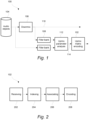
- FIG 1 shows a generalized block diagram of an audio encoding system 100 for encoding audio objects 104.
- the audio encoding system comprises a downmixing component 106 which creates a downmix signal 110 from the audio objects 104.
- the downmix signal 110 may for example be a 5.1 or 7.1 surround signal which is backwards compatible with established sound decoding systems such as Dolby Digital Plus or MPEG standards such as AAC, USAC or MP3. In further embodiments, the downmix signal is not backwards compatible.
- upmix parameters are determined at an upmix parameter analysis component 112 from the downmix signal 110 and the audio objects 104.
- the upmix parameters may correspond to elements of an upmix matrix which allows reconstruction of the audio objects 104 from the downmix signal 110.
- the upmix parameter analysis component 112 processes the downmix signal 110 and the audio objects 104 with respect to individual time/frequency tiles.
- the upmix parameters are determined for each time/frequency tile.
- an upmix matrix may be determined for each time/frequency tile.
- the upmix parameter analysis component 112 may operate in a frequency domain such as a Quadrature Mirror Filters (QMF) domain which allows frequency-selective processing.
- QMF Quadrature Mirror Filters
- the downmix signal 110 and the audio objects 104 may be transformed to the frequency domain by subjecting the downmix signal 110 and the audio objects 104 to a filter bank 108. This may for example be done by applying a QMF transform or any other suitable transform.
- the upmix parameters 114 may be organized in a vector format.
- a vector may represent an upmix parameter for reconstructing a specific audio object from the audio objects 104 at different frequency bands at a specific time frame.
- a vector may correspond to a certain matrix element in the upmix matrix, wherein the vector comprises the values of the certain matrix element for subsequent frequency bands.
- the vector may represent upmix parameters for reconstructing a specific audio object from the audio objects 104 at different time frames at a specific frequency band.
- a vector may correspond to a certain matrix element in the upmix matrix, wherein the vector comprises the values of the certain matrix element for subsequent time frames but at the same frequency band.
- Each parameter in the vector corresponds to a non-periodic quantity, for example a quantity which take a value between -9.6 and 9.4.
- a non-periodic quantity is generally meant a quantity where there is no periodicity in the values that the quantity may take. This is in contrast to a periodic quantity, such as an angle, where there is a clear periodic correspondence between the values that the quantity may take. For example, for an angle, there is a periodicity of 2 ⁇ such that e.g. the angle zero corresponds to the angle 2 ⁇ .
- the upmix parameters 114 are then received by an upmix matrix encoder 102 in the vector format.
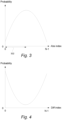
- the upmix matrix encoder will now be explained in detail in conjunction with figure 2 .
- the vector is received by a receiving component 202 and has a first element and at least one second element.
- the number of elements depends on for example the number of frequency bands in the audio signal.
- the number of elements may also depend on the number of time frames of the audio signal being encoded in one encoding operation.
- the vector is then indexed by an indexing component 204.
- the indexing component is adapted to represent each parameter in the vector by an index value which may take a predefined number of values. This representation can be done in two steps. First the parameter is quantized, and then the quantized value is indexed by an index value. By way of example, in the case where each parameter in the vector can take a value between -9.6 and 9.4, this can be done by using quantization steps of 0.2.
- the quantized values may then be indexed by indices 0-95, i.e. 96 different values. In the following examples, the index value is in the range of 0-95, but this is of course only an example, other ranges of index values are equally possible, for example 0-191 or 0-63. Smaller quantization steps may yield a less distorted decoded audio signal on a decoder side, but may also yield a larger required bit rate for the transmission of data between the audio encoding system 100 and the decoder.
- the indexed values are subsequently sent to an associating component 206 which associates each of the at least one second element with a symbol using a modulo differential encoding strategy.
- the associating component 206 is adapted to calculate a difference between the index value of the second element and the index value of the preceding element in the vector.
- the difference may be anywhere in the range of -95 to 95, i.e. it has 191 possible values. This means that when the difference is encoded using entropy coding, a probability table comprising 191 probabilities is needed, i.e. one probability for each of the 191 possible values of the differences.
- the efficiency of the encoding would be decreased since for each difference, approximately half of the 191 probabilities are impossible.
- the second element to be differential encoded has the index value 90, the possible differences are in the range -5 to +90.
- having an entropy encoding strategy where some of the probabilities are impossible for each value to be coded will decrease the efficiency of the encoding.
- the differential encoding strategy in this disclosure may overcome this problem and at the same time reduce the number of needed codes to 96 by applying a modulo 96 operation to the difference.
- the probability table is translated to a Huffman codebook.
- the symbol associated with an element in the vector is used as a codebook index.
- the encoding component 208 may then encode each of the at least one second element by representing the second element with a codeword in the Huffman codebook that is indexed by the codebook index associated with the second element.
- any other suitable entropy encoding strategy may be implemented in the encoding component 208.
- such encoding strategy may be a range coding strategy or an arithmetic coding strategy.
- p(n) p ( n ) is the probability of the plain differential index value n.
- the entropy for the modulo approach is always lower than or equal to the entropy of the conventional differential approach.
- the case where the entropy is equal is a rare case where the data to be encoded is a pathological data, i.e. non well behaved data, which in most cases does not apply to for example an upmix matrix.
- entropy coding of the symbols calculated by the modulo approach will yield in a lower or at least the same bit rate compared to entropy coding of symbols calculated by the conventional differential approach.
- the entropy coding of the symbols calculated by the modulo approach is in most cases more efficient than the entropy coding of symbols calculated by the conventional differential approach.
- a further advantage is, as mentioned above, that the number of required probabilities in the probability table in the modulo approach are approximately half the number required probabilities in the conventional non-modulo approach.
- the above has described a modulo approach for encoding the at least one second element in the vector of parameters.
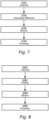
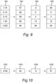
- the first element may be encoded by using the indexed value by which the first element is represented. Since the probability distribution of the index value of the first element and the modulo differential value of the at least one second element may be very different, (see figure 3 for an probability distribution of the indexed first element and figure 4 for a probability distribution of the modulo differential value, i.e. the symbol, for the at least one second element) a dedicated probability table for the first element may be needed. This requires that both the audio encoding system 100 and a corresponding decoder have such a dedicated probability table in its memory.
- the shape of the probability distributions may in some cases be quite similar, albeit shifted relative to one another. This observation may be used to approximate the probability distribution of the indexed first element by a shifted version of the probability distribution of the symbol for the at least one second element.
- Such shifting may be implemented by adapting the associating component 206 to associate the first element in the vector with a symbol by shifting the index value representing the first element in the vector by an off-set value and subsequently apply modulo 96 (or corresponding value) to the shifted index value.
- idx shifted 1 idx 1 ⁇ abs _ offset modN Q
- the thus achieved symbol is used by the encoding component 208 which encodes the first element by entropy coding of the symbol associated with the first element using the same probability table that is used to encode the at least one second element.
- the off-set value may be equal to, or at least close to, the difference between a most probable index value for the first element and the most probable symbol for the at least one second element in the probability table.
- the most probable index value for the first element is denoted by the arrow 302.
- the value denoted by the arrow 302 will be the off-set value used.
- the encoding component 208 may encode the first element in the vector using the same Huffman codebook that is used to encode the at least one second element by representing the first element with a codeword in the Huffman codebook that is indexed by the codebook index associated with the first element.
- the memory on which the codebook is stored is advantageously a fast memory, and thus expensive.
- the encoder may thus be cheaper than in the case where two probability tables are used.
- an audio encoding system 100 using a vector from an upmix matrix as the vector of parameters being encoded is just an example application.
- the method for encoding a vector of parameters may be used in other applications in an audio encoding system, for example when encoding other internal parameters in downmix encoding system such as parameters used in a parametric bandwidth extension system such as spectral band replication (SBR).
- SBR spectral band replication
- Figure 5 is a generalized block diagram of an audio decoding system 500 for recreating encoded audio objects from a coded downmix signal 510 and a coded upmix matrix 512.
- the coded downmix signal 510 is received by a downmix receiving component 506 where the signal is decoded and, if not already in a suitable frequency domain, transformed to a suitable frequency domain.
- the decoded downmix signal 516 is then sent to the upmix component 508.
- the encoded audio objects are recreated using the decoded downmix signal 516 and a decoded upmix matrix 504.
- the upmix component 508 may perform a matrix operation in which the decoded upmix matrix 504 is multiplied by a vector comprising the decoded downmix signals 516.
- the decoding process of the upmix matrix is described below.
- the audio decoding system 500 further comprises a rendering component 514 which output an audio signal based on the reconstructed audio objects 518 depending on what type of playback unit that is connected to the audio decoding system 500.
- a coded upmix matrix 512 is received by an upmix matrix decoder 502 which will now be explained in detail in conjunction with figure 6 .
- the upmix matrix decoder 502 is configured to decode a vector of entropy coded symbols in an audio decoding system into a vector of parameters relating to a non-periodic quantity.
- the vector of entropy coded symbols comprises a first entropy coded symbol and at least one second entropy coded symbol and the vector of parameters comprises a first element and at least a second element.
- the coded upmix matrix 512 is thus received by a receiving component 602 in a vector format.
- the decoder 502 further comprises an indexing component 604 configured to represent each entropy coded symbol in the vector by a symbol which may take N values by using a probability table. N may for example be 96.
- An associating component 606 is configured to associate the first entropy coded symbol with an index value by any suitable means, depending on the encoding method used for encoding the first element in the vector of parameters. The symbol for each of the second codes and the index value for the first code is then used by the associating component 606 which associates each of the at least one second entropy coded symbol with an index value.
- the index value of the at least one second entropy coded symbol is calculated by first calculating the sum of the index value associated with the entropy coded symbol preceding the second entropy coded symbol in the vector of entropy coded symbols and the symbol representing the second entropy coded symbol. Subsequently, modulo N is the applied to the sum. Assuming, without loss of generality, that the minimum index value is 0 and the maximum index value is N-1, e.g. 95.
- the upmix matrix decoder 502 further comprises a decoding component 608 which is configured to represent the at least one second element of the vector of parameters by a parameter value corresponding to the index value associated with the at least one second entropy coded symbol.
- This representation is thus the decoded version of the parameter encoded by for example the audio encoding system 100 shown in figure 1 . In other words, this representation is equal to the quantized parameter encoded by the audio encoding system 100 shown in figure 1 .
- each entropy coded symbol in the vector of entropy coded symbol is represented by symbol using the same probability table for all entropy coded symbols in the vector of entropy coded symbols.
- the association component 606 may be configure to associating the first entropy coded symbol with an index value by first shifting the symbol representing the first entropy coded symbol in the vector of entropy coded symbols by an off-set value. Modulo N is then applied to the shifted symbol.
- the decoding component 608 is configured to represent the first element of the vector of parameters by a parameter value corresponding to the index value associated with the first entropy coded symbol. This representation is thus the decoded version of the parameter encoded by for example the audio encoding system 100 shown in figure 1 .
- Figure 7 and 9 describes an encoding method for four (4) second elements in a vector of parameters.
- the input vector 902 thus comprises five parameters.
- the parameters may take any value between a min value and a max value.
- the min value is -9.6 and the max value is 9.4.
- the first step S702 in the encoding method is to represent each parameter in the vector 902 by an index value which may take N values.
- N is chosen to be 96, which means that the quantization step size is 0.2.
- the next step S704 is to calculate the difference between each of the second elements, i.e. the four upper parameters in vector 904, and its preceding element.
- the resulting vector 906 thus comprises four differential values - the four upper values in the vector 906.
- the differential values may be both negative, zero and positive. As explained above, it is advantageous to have differential values which only can take N values, in this case 96 values. To achieve this, in the next step S706 of this method, modulo 96 is applied to the second elements in the vector 906. The resulting vector 908 does not contain any negative values. The thus achieved symbol shown in vector 908 is then used for encoding the second elements of the vector in the final step S708 of the method shown in figure 7 by entropy coding of the symbol associated with the at least one second element based on a probability table comprising probabilities of the symbols shown in vector 908.
- the first element is not handled after the indexing step S702.
- a method for encoding the first element in the input vector is described. The same assumption as made in the above description of figure 7 and 9 regarding the min and max value of the parameters and the number of possible index values are valid when describing figure 8 and 10 .
- the first element 1002 is received by the encoder.
- the parameter of the first element is represented by an index value 1004.
- the indexed value 1004 is shifted by an off-set value. In this example, the value of the off-set is 49. This value is calculated as described above.
- modulo 96 is applied to the shifted index value 1006.
- the resulting value 1008 may then be used in an encoding step S802 to encode the first element by entropy coding of the symbol 1008 using the same probability table that is used to encode the at least one second element in figure 7 .
- Figure 11 shows an embodiment 102' of the upmix matrix encoding component 102 in figure 1 .
- the upmix matrix encoder 102' may be used for encoding an upmix matrix in an audio encoding system, for example the audio encoding system 100 shown in figure 1 .
- each row of the upmix matrix comprises M elements allowing reconstruction of an audio object from a downmix signal comprising M channels.
- encoding and sending all M upmix matrix elements per object and T/F tile, one for each downmix channel can require an undesirably high bit rate. This can be reduced by "sparsening" of the upmix matrix, i.e., trying to reduce the number of non-zero elements. In some cases, four out of five elements are zero and only a single downmix channel is used as basis for reconstruction of the audio object. Sparse matrices have other probability distributions of the coded indices (absolute or differential) than non-sparse matrices.
- the upmix matrix comprises a large portion of zeros, such that the value zero becomes more probable than 0.5, and Huffman coding is used
- the coding efficiency will decrease since the Huffman coding algorithm is inefficient when a specific value, e.g. zero, has a probability of more than 0.5.
- a strategy may thus be to select a subset of the upmix matrix elements and only encode and transmit those to a decoder. This may decrease the required bit rate of an audio encoding/decoding system since less data is transmitted.
- a dedicated coding mode for sparse matrices may be used which will be explained in detail below.
- the encoder 102' comprises a receiving component 1102 adapted to receive each row in the upmix matrix.
- the encoder 102' further comprises a selection component 1104 adapted to select a subset of elements from the M elements of the row in the upmix matrix. In most cases, the subset comprises all elements not having a zero value. But according to some embodiment, the selection component may choose to not select an element having a non-zero value, for example an element having a value close to zero.
- the selected subset of elements may comprise the same number of elements for each row of the upmix matrix. To further reduce the required bit rate, the number of selected elements may be one (1).
- the encoder 102' further comprises an encoding component 1106 which is adapted to represent each element in the selected subset of elements by a value and a position in the upmix matrix.
- the encoding component 1106 is further adapted to encode the value and the position in the upmix matrix of each element in the selected subset of elements. It may for example be adapted to encode the value using modulo differential encoding as described above.
- the values of the elements of the selected subsets of elements form one or more vector of parameters.
- Each parameter in the vector of parameters corresponds to one of the plurality of frequency bands or the plurality of time frames.
- the vector of parameters may thus be coded using modulo differential encoding as described above.
- the vector of parameters may be coded using regular differential encoding.
- the encoding component 1106 is adapted to code each value separately, using fixed rate coding of the true quantization value, i.e. not differential encoded, of each value.
- the following average bit rates have been observed:
- Modulo differential coding for both the value of the element and the position of the element: 20 kb/sec.
- the encoding component 1106 may be adapted to encode the position in the upmix matrix of each element in the subset of elements in the same way as the value.
- the encoding component 1106 may also be adapted to encode the position in the upmix matrix of each element in the subset of elements in a different way compared to the encoding of the value.
- the positions of the elements of the selected subsets of elements form one or more vector of parameters.
- Each parameter in the vector of parameters corresponds to one of the plurality of frequency bands or plurality of time frame.
- the vector of parameters is thus encoded using differential coding or modulo differential coding as described above.
- the encoder 102' may be combined with the encoder 102 in figure 2 to achieve modulo differential coding of a sparse upmix matrix according to the above.
- An upmix matrix is received, for example by the receiving component 1102 in figure 11 .
- the method comprising selecting a subset S1302 from the M, e.g. 5, elements of the row in the upmix matrix.
- Each element in the selected subset of elements is then represented S1304 by a value and a position in the upmix matrix.
- one element is selected S1302 as the subset, e.g. element number 3 having a value of 2.34.
- the representation may thus be a vector 1404 having two fields.
- the first field in the vector 1404 represents the value, e.g. 2.34
- the second field in the vector 1404 represents the position, e.g. 3.
- the representation may thus be a vector 1504 having four fields.
- the first field in the vector 1504 represents the value of the first element, e.g. 2.34
- the second field in the vector 1504 represents the position of the first element, e.g. 3.
- the third field in the vector 1504 represents the value of the second element, e.g. - 1.81
- the fourth field in the vector 1504 represents the position of the second element, e.g. 5.
- the representations 1404, 1504 is then encoded S1306 according to the above.
- FIG 12 is a generalized block diagram of an audio decoding system 1200.
- the decoder 1200 comprises a receiving component 1206 configured to receive a downmix signal 1210 comprising M channels and at least one encoded element 1204 representing a subset of M elements of a row in an upmix matrix.
- Each of the encoded elements comprises a value and a position in the row in the upmix matrix, the position indicating one of the M channels of the downmix signal 1210 to which the encoded element corresponds.
- the at least one encoded element 1204 is decoded by an upmix matrix element decoding component 1202.
- the upmix matrix element decoding component 1202 is configured to decode the at least one encoded element 1204 according to the encoding strategy used for encoding the at least one encoded element 1204.
- the at least one decoded element 1214 is then sent to the reconstructing component 1208 which is configured to reconstruct a time/frequency tile of the audio object from the downmix signal 1210 by forming a linear combination of the downmix channels that correspond to the at least one encoded element 1204.
- each downmix channel is multiplied by the value of its corresponding encoded element 1204.
- the decoded element 1214 comprises the value 1.1 and the position 2
- the time/frequency tile of the second downmix channel is multiplied by 1.1 and this is then used for reconstructing the audio object.
- the audio decoding system 500 further comprises a rendering component 1216 which output an audio signal based on the reconstructed audio object 1218.
- the type of audio signal depends on what type of playback unit that are connected to the audio decoding system 1200. For example, if a pair of headphones is connected to the audio decoding system 1200, a stereo signal may be outputted by the rendering component 1216.
- the systems and methods disclosed hereinabove may be implemented as software, firmware, hardware or a combination thereof.
- the division of tasks between functional units referred to in the above description does not necessarily correspond to the division into physical units; to the contrary, one physical component may have multiple functionalities, and one task may be carried out by several physical components in cooperation.
- Certain components or all components may be implemented as software executed by a digital signal processor or microprocessor, or be implemented as hardware or as an application-specific integrated circuit.
- Such software may be distributed on computer readable media, which may comprise computer storage media (or non-transitory media) and communication media (or transitory media).
- Computer storage media includes both volatile and nonvolatile, removable and non-removable media implemented in any method or technology for storage of information such as computer readable instructions, data structures, program modules or other data.
- Computer storage media includes, but is not limited to, RAM, ROM, EEPROM, flash memory or other memory technology, CD-ROM, digital versatile disks (DVD) or other optical disk storage, magnetic cassettes, magnetic tape, magnetic disk storage or other magnetic storage devices, or any other medium which can be used to store the desired information and which can be accessed by a computer.
- communication media typically embodies computer readable instructions, data structures, program modules or other data in a modulated data signal such as a carrier wave or other transport mechanism and includes any information delivery media.
Landscapes
- Engineering & Computer Science (AREA)
- Physics & Mathematics (AREA)
- Signal Processing (AREA)
- Acoustics & Sound (AREA)
- Multimedia (AREA)
- Computational Linguistics (AREA)
- Health & Medical Sciences (AREA)
- Audiology, Speech & Language Pathology (AREA)
- Human Computer Interaction (AREA)
- Spectroscopy & Molecular Physics (AREA)
- Mathematical Physics (AREA)
- Algebra (AREA)
- General Physics & Mathematics (AREA)
- Mathematical Analysis (AREA)
- Mathematical Optimization (AREA)
- Pure & Applied Mathematics (AREA)
- Theoretical Computer Science (AREA)
- Compression, Expansion, Code Conversion, And Decoders (AREA)
- Stereophonic System (AREA)
- Error Detection And Correction (AREA)
Priority Applications (1)
| Application Number | Priority Date | Filing Date | Title |
|---|---|---|---|
| EP23205287.8A EP4290510A3 (en) | 2013-05-24 | 2014-05-23 | Audio encoder |
Applications Claiming Priority (5)
| Application Number | Priority Date | Filing Date | Title |
|---|---|---|---|
| US201361827264P | 2013-05-24 | 2013-05-24 | |
| EP19193266.4A EP3605532B1 (en) | 2013-05-24 | 2014-05-23 | Audio encoder |
| EP14725736.4A EP3005350B1 (en) | 2013-05-24 | 2014-05-23 | Audio encoder and decoder |
| PCT/EP2014/060731 WO2014187988A2 (en) | 2013-05-24 | 2014-05-23 | Audio encoder and decoder |
| EP17164543.5A EP3252757B1 (en) | 2013-05-24 | 2014-05-23 | Audio encoder and decoder |
Related Parent Applications (3)
| Application Number | Title | Priority Date | Filing Date |
|---|---|---|---|
| EP17164543.5A Division EP3252757B1 (en) | 2013-05-24 | 2014-05-23 | Audio encoder and decoder |
| EP19193266.4A Division EP3605532B1 (en) | 2013-05-24 | 2014-05-23 | Audio encoder |
| EP14725736.4A Division EP3005350B1 (en) | 2013-05-24 | 2014-05-23 | Audio encoder and decoder |
Related Child Applications (1)
| Application Number | Title | Priority Date | Filing Date |
|---|---|---|---|
| EP23205287.8A Division EP4290510A3 (en) | 2013-05-24 | 2014-05-23 | Audio encoder |
Publications (2)
| Publication Number | Publication Date |
|---|---|
| EP3961622A1 EP3961622A1 (en) | 2022-03-02 |
| EP3961622B1 true EP3961622B1 (en) | 2023-11-01 |
Family
ID=50771514
Family Applications (5)
| Application Number | Title | Priority Date | Filing Date |
|---|---|---|---|
| EP21198240.0A Active EP3961622B1 (en) | 2013-05-24 | 2014-05-23 | Audio encoder |
| EP23205287.8A Pending EP4290510A3 (en) | 2013-05-24 | 2014-05-23 | Audio encoder |
| EP14725736.4A Active EP3005350B1 (en) | 2013-05-24 | 2014-05-23 | Audio encoder and decoder |
| EP17164543.5A Active EP3252757B1 (en) | 2013-05-24 | 2014-05-23 | Audio encoder and decoder |
| EP19193266.4A Active EP3605532B1 (en) | 2013-05-24 | 2014-05-23 | Audio encoder |
Family Applications After (4)
| Application Number | Title | Priority Date | Filing Date |
|---|---|---|---|
| EP23205287.8A Pending EP4290510A3 (en) | 2013-05-24 | 2014-05-23 | Audio encoder |
| EP14725736.4A Active EP3005350B1 (en) | 2013-05-24 | 2014-05-23 | Audio encoder and decoder |
| EP17164543.5A Active EP3252757B1 (en) | 2013-05-24 | 2014-05-23 | Audio encoder and decoder |
| EP19193266.4A Active EP3605532B1 (en) | 2013-05-24 | 2014-05-23 | Audio encoder |
Country Status (18)
Families Citing this family (15)
| Publication number | Priority date | Publication date | Assignee | Title |
|---|---|---|---|---|
| CN105229733B (zh) | 2013-05-24 | 2019-03-08 | 杜比国际公司 | 包括音频对象的音频场景的高效编码 |
| ES2640815T3 (es) | 2013-05-24 | 2017-11-06 | Dolby International Ab | Codificación eficiente de escenas de audio que comprenden objetos de audio |
| CA3123374C (en) | 2013-05-24 | 2024-01-02 | Dolby International Ab | Coding of audio scenes |
| US9704493B2 (en) | 2013-05-24 | 2017-07-11 | Dolby International Ab | Audio encoder and decoder |
| CN105229731B (zh) | 2013-05-24 | 2017-03-15 | 杜比国际公司 | 根据下混的音频场景的重构 |
| WO2015059154A1 (en) | 2013-10-21 | 2015-04-30 | Dolby International Ab | Audio encoder and decoder |
| US9756448B2 (en) | 2014-04-01 | 2017-09-05 | Dolby International Ab | Efficient coding of audio scenes comprising audio objects |
| GB2528460B (en) * | 2014-07-21 | 2018-05-30 | Gurulogic Microsystems Oy | Encoder, decoder and method |
| JP2018526669A (ja) * | 2015-07-06 | 2018-09-13 | ノキア テクノロジーズ オサケユイチア | オーディオ信号デコーダのためのビット・エラー検出器 |
| US10249312B2 (en) | 2015-10-08 | 2019-04-02 | Qualcomm Incorporated | Quantization of spatial vectors |
| US9961475B2 (en) * | 2015-10-08 | 2018-05-01 | Qualcomm Incorporated | Conversion from object-based audio to HOA |
| KR102546098B1 (ko) * | 2016-03-21 | 2023-06-22 | 한국전자통신연구원 | 블록 기반의 오디오 부호화/복호화 장치 및 그 방법 |
| CN107886960B (zh) * | 2016-09-30 | 2020-12-01 | 华为技术有限公司 | 一种音频信号重建方法及装置 |
| CN116324979A (zh) * | 2020-09-28 | 2023-06-23 | 三星电子株式会社 | 音频编码装置和方法,以及音频解码装置和方法 |
| US12259827B2 (en) * | 2023-01-31 | 2025-03-25 | Avago Technologies International Sales Pte. Limited | Systems and methods for address scrambling |
Family Cites Families (41)
| Publication number | Priority date | Publication date | Assignee | Title |
|---|---|---|---|---|
| JPS5470801A (en) | 1977-11-16 | 1979-06-07 | Mitsubishi Monsanto Chem | Sound shielding plate |
| JPS615159A (ja) | 1984-06-16 | 1986-01-10 | 株式会社アイジー技術研究所 | サイデイングボ−ド |
| DE4423612A1 (de) | 1994-07-06 | 1996-01-11 | Basf Ag | 2-[(Dihydro)pyrazolyl-3'-oxymethylen]-anilide, Verfahren zu ihrer Herstelung und ihre Verwendung |
| KR100844810B1 (ko) | 2000-12-22 | 2008-07-09 | 소니 가부시끼 가이샤 | 부호화 장치 및 복호 장치 |
| SE0202159D0 (sv) * | 2001-07-10 | 2002-07-09 | Coding Technologies Sweden Ab | Efficientand scalable parametric stereo coding for low bitrate applications |
| JP2003110429A (ja) * | 2001-09-28 | 2003-04-11 | Sony Corp | 符号化方法及び装置、復号方法及び装置、伝送方法及び装置、並びに記録媒体 |
| JP3982397B2 (ja) | 2001-11-28 | 2007-09-26 | 日本ビクター株式会社 | 可変長符号化データ復号化用プログラム及び可変長符号化データ受信用プログラム |
| US7263692B2 (en) * | 2003-06-30 | 2007-08-28 | Intel Corporation | System and method for software-pipelining of loops with sparse matrix routines |
| US7912122B2 (en) | 2004-01-20 | 2011-03-22 | Panasonic Corporation | Picture coding method, picture decoding method, picture coding apparatus, picture decoding apparatus |
| US7895034B2 (en) | 2004-09-17 | 2011-02-22 | Digital Rise Technology Co., Ltd. | Audio encoding system |
| US20060080090A1 (en) | 2004-10-07 | 2006-04-13 | Nokia Corporation | Reusing codebooks in parameter quantization |
| EP1691348A1 (en) | 2005-02-14 | 2006-08-16 | Ecole Polytechnique Federale De Lausanne | Parametric joint-coding of audio sources |
| US20070055510A1 (en) | 2005-07-19 | 2007-03-08 | Johannes Hilpert | Concept for bridging the gap between parametric multi-channel audio coding and matrixed-surround multi-channel coding |
| TWI396188B (zh) | 2005-08-02 | 2013-05-11 | Dolby Lab Licensing Corp | 依聆聽事件之函數控制空間音訊編碼參數的技術 |
| KR20070037945A (ko) | 2005-10-04 | 2007-04-09 | 삼성전자주식회사 | 오디오 신호의 부호화/복호화 방법 및 장치 |
| KR100878833B1 (ko) | 2005-10-05 | 2009-01-14 | 엘지전자 주식회사 | 신호 처리 방법 및 이의 장치, 그리고 인코딩 및 디코딩방법 및 이의 장치 |
| KR101370017B1 (ko) | 2006-02-22 | 2014-03-05 | 오렌지 | Celp 기술에서의 디지털 오디오 신호의 개선된 코딩/디코딩 |
| CN101390158B (zh) * | 2006-02-24 | 2012-03-14 | 法国电信公司 | 量化索引的编码方法、解码信号包络方法、编解码模块 |
| ATE536612T1 (de) * | 2006-10-16 | 2011-12-15 | Dolby Int Ab | Verbesserte kodierungs- und parameterdarstellung von mehrkanaliger abwärtsgemischter objektkodierung |
| US7953595B2 (en) | 2006-10-18 | 2011-05-31 | Polycom, Inc. | Dual-transform coding of audio signals |
| CN102089810B (zh) | 2008-07-10 | 2013-05-08 | 沃伊斯亚吉公司 | 多基准线性预测系数滤波器量化和逆量化设备及方法 |
| EP3246918B1 (en) * | 2008-07-11 | 2023-06-14 | Fraunhofer-Gesellschaft zur Förderung der angewandten Forschung e.V. | Audio decoder, method for decoding an audio signal and computer program |
| WO2010040522A2 (en) * | 2008-10-08 | 2010-04-15 | Fraunhofer-Gesellschaft zur Förderung der angewandten Forschung e. V. | Multi-resolution switched audio encoding/decoding scheme |
| EP2214161A1 (en) * | 2009-01-28 | 2010-08-04 | Fraunhofer-Gesellschaft zur Förderung der angewandten Forschung e.V. | Apparatus, method and computer program for upmixing a downmix audio signal |
| US8194862B2 (en) | 2009-07-31 | 2012-06-05 | Activevideo Networks, Inc. | Video game system with mixing of independent pre-encoded digital audio bitstreams |
| UA48138U (ru) | 2009-08-31 | 2010-03-10 | Винницкий Национальный Технический Университет | Способ направленного поиска векторов при уплотнении языковых сигналов |
| KR101710113B1 (ko) | 2009-10-23 | 2017-02-27 | 삼성전자주식회사 | 위상 정보와 잔여 신호를 이용한 부호화/복호화 장치 및 방법 |
| US9117458B2 (en) | 2009-11-12 | 2015-08-25 | Lg Electronics Inc. | Apparatus for processing an audio signal and method thereof |
| US8692848B2 (en) | 2009-12-17 | 2014-04-08 | Broadcom Corporation | Method and system for tile mode renderer with coordinate shader |
| EP2543039B1 (en) | 2010-03-02 | 2018-11-28 | Telefonaktiebolaget LM Ericsson (publ) | Source code adaption based on communication link quality and source coding delay. |
| DK2556502T3 (en) | 2010-04-09 | 2019-03-04 | Dolby Int Ab | MDCT-BASED COMPLEX PREVIEW Stereo Decoding |
| EP4404560A3 (en) | 2010-04-13 | 2024-08-21 | Fraunhofer-Gesellschaft zur Förderung der angewandten Forschung e.V. | Audio decoding method for processing stereo audio signals using a variable prediction direction |
| US9112591B2 (en) | 2010-04-16 | 2015-08-18 | Samsung Electronics Co., Ltd. | Apparatus for encoding/decoding multichannel signal and method thereof |
| KR101798079B1 (ko) * | 2010-05-10 | 2017-11-16 | 삼성전자주식회사 | 픽셀값의 차분을 이용하여 영상 프레임을 부호화하는 방법 및 이를 위한 장치 |
| US8660195B2 (en) | 2010-08-10 | 2014-02-25 | Qualcomm Incorporated | Using quantized prediction memory during fast recovery coding |
| US9111526B2 (en) * | 2010-10-25 | 2015-08-18 | Qualcomm Incorporated | Systems, method, apparatus, and computer-readable media for decomposition of a multichannel music signal |
| EP3096315B1 (en) * | 2011-04-20 | 2019-10-16 | Panasonic Intellectual Property Corporation of America | Device and method for execution of huffman coding |
| US9966080B2 (en) * | 2011-11-01 | 2018-05-08 | Koninklijke Philips N.V. | Audio object encoding and decoding |
| US9223376B2 (en) * | 2012-03-23 | 2015-12-29 | Qualcomm Incorporated | Managing electrical current in a portable computing device when two or more communications overlap in drawing power during a transmission |
| MX342150B (es) * | 2012-07-09 | 2016-09-15 | Koninklijke Philips Nv | Codificacion y decodificacion de señales de audio. |
| US9704493B2 (en) * | 2013-05-24 | 2017-07-11 | Dolby International Ab | Audio encoder and decoder |
-
2014
- 2014-05-23 US US14/892,722 patent/US9704493B2/en active Active
- 2014-05-23 MX MX2015015926A patent/MX350117B/es active IP Right Grant
- 2014-05-23 BR BR112015029031-0A patent/BR112015029031B1/pt active IP Right Grant
- 2014-05-23 EP EP21198240.0A patent/EP3961622B1/en active Active
- 2014-05-23 KR KR1020207002641A patent/KR102192245B1/ko active Active
- 2014-05-23 CA CA2990261A patent/CA2990261C/en active Active
- 2014-05-23 CN CN201910125157.XA patent/CN110085238B/zh active Active
- 2014-05-23 CN CN201480029565.0A patent/CN105229729B/zh active Active
- 2014-05-23 RU RU2015155311A patent/RU2643489C2/ru active
- 2014-05-23 AU AU2014270301A patent/AU2014270301B2/en active Active
- 2014-05-23 WO PCT/EP2014/060731 patent/WO2014187988A2/en active Application Filing
- 2014-05-23 MX MX2017010953A patent/MX375380B/es unknown
- 2014-05-23 MY MYPI2019003013A patent/MY199032A/en unknown
- 2014-05-23 EP EP23205287.8A patent/EP4290510A3/en active Pending
- 2014-05-23 PL PL14725736T patent/PL3005350T3/pl unknown
- 2014-05-23 ES ES19193266T patent/ES2902518T3/es active Active
- 2014-05-23 CA CA2911746A patent/CA2911746C/en active Active
- 2014-05-23 KR KR1020217015014A patent/KR102384348B1/ko active Active
- 2014-05-23 ES ES14725736.4T patent/ES2629025T3/es active Active
- 2014-05-23 KR KR1020227011202A patent/KR102459010B1/ko active Active
- 2014-05-23 KR KR1020237028826A patent/KR102715092B1/ko active Active
- 2014-05-23 DK DK14725736.4T patent/DK3005350T3/en active
- 2014-05-23 KR KR1020177020394A patent/KR101895198B1/ko active Active
- 2014-05-23 KR KR1020247033073A patent/KR20240151867A/ko active Pending
- 2014-05-23 KR KR1020157036397A patent/KR101763131B1/ko active Active
- 2014-05-23 SG SG11201509001YA patent/SG11201509001YA/en unknown
- 2014-05-23 SG SG10201710019SA patent/SG10201710019SA/en unknown
- 2014-05-23 EP EP14725736.4A patent/EP3005350B1/en active Active
- 2014-05-23 RU RU2018101246A patent/RU2676041C1/ru active
- 2014-05-23 JP JP2016514442A patent/JP6105159B2/ja active Active
- 2014-05-23 CA CA3163664A patent/CA3163664A1/en active Pending
- 2014-05-23 MY MYPI2015703952A patent/MY173644A/en unknown
- 2014-05-23 ES ES21198240T patent/ES2965423T3/es active Active
- 2014-05-23 EP EP17164543.5A patent/EP3252757B1/en active Active
- 2014-05-23 KR KR1020227036517A patent/KR102572382B1/ko active Active
- 2014-05-23 KR KR1020187024874A patent/KR102072777B1/ko active Active
- 2014-05-23 EP EP19193266.4A patent/EP3605532B1/en active Active
- 2014-05-23 CA CA3077876A patent/CA3077876C/en active Active
- 2014-05-23 KR KR1020207035676A patent/KR102280461B1/ko active Active
- 2014-05-23 UA UAA201512264A patent/UA112833C2/uk unknown
-
2015
- 2015-11-02 IL IL242410A patent/IL242410B/en active IP Right Grant
- 2015-11-19 MX MX2020010038A patent/MX2020010038A/es unknown
-
2017
- 2017-03-01 JP JP2017038524A patent/JP6573640B2/ja active Active
- 2017-07-06 US US15/643,416 patent/US9940939B2/en active Active
-
2018
- 2018-04-05 US US15/946,529 patent/US10418038B2/en active Active
- 2018-12-14 RU RU2018144368A patent/RU2710909C1/ru active
-
2019
- 2019-08-13 JP JP2019148473A patent/JP6920382B2/ja active Active
- 2019-09-17 US US16/573,488 patent/US10714104B2/en active Active
-
2020
- 2020-07-10 US US16/925,898 patent/US11024320B2/en active Active
-
2021
- 2021-05-28 US US17/333,527 patent/US11594233B2/en active Active
- 2021-07-26 JP JP2021121510A patent/JP7258086B2/ja active Active
-
2023
- 2023-02-27 US US18/114,885 patent/US12236961B2/en active Active
- 2023-04-04 JP JP2023060522A patent/JP7585379B2/ja active Active
-
2024
- 2024-11-06 JP JP2024194253A patent/JP2025028867A/ja active Pending
-
2025
- 2025-04-10 JP JP2025064679A patent/JP2025100674A/ja active Pending
Also Published As
Similar Documents
| Publication | Publication Date | Title |
|---|---|---|
| US12236961B2 (en) | Audio encoder and decoder | |
| HK1246958B (en) | Audio encoder and decoder | |
| HK1246958A1 (en) | Audio encoder and decoder | |
| HK1217246B (en) | Audio encoder and decoder |
Legal Events
| Date | Code | Title | Description |
|---|---|---|---|
| PUAI | Public reference made under article 153(3) epc to a published international application that has entered the european phase |
Free format text: ORIGINAL CODE: 0009012 |
|
| STAA | Information on the status of an ep patent application or granted ep patent |
Free format text: STATUS: THE APPLICATION HAS BEEN PUBLISHED |
|
| AC | Divisional application: reference to earlier application |
Ref document number: 3005350 Country of ref document: EP Kind code of ref document: P Ref document number: 3252757 Country of ref document: EP Kind code of ref document: P Ref document number: 3605532 Country of ref document: EP Kind code of ref document: P |
|
| AK | Designated contracting states |
Kind code of ref document: A1 Designated state(s): AL AT BE BG CH CY CZ DE DK EE ES FI FR GB GR HR HU IE IS IT LI LT LU LV MC MK MT NL NO PL PT RO RS SE SI SK SM TR |
|
| RAP3 | Party data changed (applicant data changed or rights of an application transferred) |
Owner name: DOLBY INTERNATIONAL AB |
|
| STAA | Information on the status of an ep patent application or granted ep patent |
Free format text: STATUS: REQUEST FOR EXAMINATION WAS MADE |
|
| 17P | Request for examination filed |
Effective date: 20220902 |
|
| RBV | Designated contracting states (corrected) |
Designated state(s): AL AT BE BG CH CY CZ DE DK EE ES FI FR GB GR HR HU IE IS IT LI LT LU LV MC MK MT NL NO PL PT RO RS SE SI SK SM TR |
|
| RAP3 | Party data changed (applicant data changed or rights of an application transferred) |
Owner name: DOLBY INTERNATIONAL AB |
|
| GRAP | Despatch of communication of intention to grant a patent |
Free format text: ORIGINAL CODE: EPIDOSNIGR1 |
|
| STAA | Information on the status of an ep patent application or granted ep patent |
Free format text: STATUS: GRANT OF PATENT IS INTENDED |
|
| RIC1 | Information provided on ipc code assigned before grant |
Ipc: G10L 19/00 20130101ALI20221220BHEP Ipc: G10L 19/008 20130101ALI20221220BHEP Ipc: G10L 19/038 20130101AFI20221220BHEP |
|
| INTG | Intention to grant announced |
Effective date: 20230110 |
|
| GRAJ | Information related to disapproval of communication of intention to grant by the applicant or resumption of examination proceedings by the epo deleted |
Free format text: ORIGINAL CODE: EPIDOSDIGR1 |
|
| STAA | Information on the status of an ep patent application or granted ep patent |
Free format text: STATUS: REQUEST FOR EXAMINATION WAS MADE |
|
| GRAP | Despatch of communication of intention to grant a patent |
Free format text: ORIGINAL CODE: EPIDOSNIGR1 |
|
| STAA | Information on the status of an ep patent application or granted ep patent |
Free format text: STATUS: GRANT OF PATENT IS INTENDED |
|
| INTC | Intention to grant announced (deleted) | ||
| P01 | Opt-out of the competence of the unified patent court (upc) registered |
Effective date: 20230418 |
|
| INTG | Intention to grant announced |
Effective date: 20230526 |
|
| GRAS | Grant fee paid |
Free format text: ORIGINAL CODE: EPIDOSNIGR3 |
|
| GRAA | (expected) grant |
Free format text: ORIGINAL CODE: 0009210 |
|
| STAA | Information on the status of an ep patent application or granted ep patent |
Free format text: STATUS: THE PATENT HAS BEEN GRANTED |
|
| AC | Divisional application: reference to earlier application |
Ref document number: 3005350 Country of ref document: EP Kind code of ref document: P Ref document number: 3252757 Country of ref document: EP Kind code of ref document: P Ref document number: 3605532 Country of ref document: EP Kind code of ref document: P |
|
| AK | Designated contracting states |
Kind code of ref document: B1 Designated state(s): AL AT BE BG CH CY CZ DE DK EE ES FI FR GB GR HR HU IE IS IT LI LT LU LV MC MK MT NL NO PL PT RO RS SE SI SK SM TR |
|
| REG | Reference to a national code |
Ref country code: GB Ref legal event code: FG4D |
|
| REG | Reference to a national code |
Ref country code: CH Ref legal event code: EP |
|
| REG | Reference to a national code |
Ref country code: DE Ref legal event code: R096 Ref document number: 602014088792 Country of ref document: DE |
|
| REG | Reference to a national code |
Ref country code: IE Ref legal event code: FG4D |
|
| REG | Reference to a national code |
Ref country code: NL Ref legal event code: FP |
|
| REG | Reference to a national code |
Ref country code: LT Ref legal event code: MG9D |
|
| PG25 | Lapsed in a contracting state [announced via postgrant information from national office to epo] |
Ref country code: GR Free format text: LAPSE BECAUSE OF FAILURE TO SUBMIT A TRANSLATION OF THE DESCRIPTION OR TO PAY THE FEE WITHIN THE PRESCRIBED TIME-LIMIT Effective date: 20240202 |
|
| PG25 | Lapsed in a contracting state [announced via postgrant information from national office to epo] |
Ref country code: IS Free format text: LAPSE BECAUSE OF FAILURE TO SUBMIT A TRANSLATION OF THE DESCRIPTION OR TO PAY THE FEE WITHIN THE PRESCRIBED TIME-LIMIT Effective date: 20240301 |
|
| PG25 | Lapsed in a contracting state [announced via postgrant information from national office to epo] |
Ref country code: LT Free format text: LAPSE BECAUSE OF FAILURE TO SUBMIT A TRANSLATION OF THE DESCRIPTION OR TO PAY THE FEE WITHIN THE PRESCRIBED TIME-LIMIT Effective date: 20231101 |
|
| REG | Reference to a national code |
Ref country code: AT Ref legal event code: MK05 Ref document number: 1628157 Country of ref document: AT Kind code of ref document: T Effective date: 20231101 Ref country code: ES Ref legal event code: FG2A Ref document number: 2965423 Country of ref document: ES Kind code of ref document: T3 Effective date: 20240415 |
|
| PG25 | Lapsed in a contracting state [announced via postgrant information from national office to epo] |
Ref country code: AT Free format text: LAPSE BECAUSE OF FAILURE TO SUBMIT A TRANSLATION OF THE DESCRIPTION OR TO PAY THE FEE WITHIN THE PRESCRIBED TIME-LIMIT Effective date: 20231101 |
|
| PG25 | Lapsed in a contracting state [announced via postgrant information from national office to epo] |
Ref country code: LT Free format text: LAPSE BECAUSE OF FAILURE TO SUBMIT A TRANSLATION OF THE DESCRIPTION OR TO PAY THE FEE WITHIN THE PRESCRIBED TIME-LIMIT Effective date: 20231101 Ref country code: IS Free format text: LAPSE BECAUSE OF FAILURE TO SUBMIT A TRANSLATION OF THE DESCRIPTION OR TO PAY THE FEE WITHIN THE PRESCRIBED TIME-LIMIT Effective date: 20240301 Ref country code: GR Free format text: LAPSE BECAUSE OF FAILURE TO SUBMIT A TRANSLATION OF THE DESCRIPTION OR TO PAY THE FEE WITHIN THE PRESCRIBED TIME-LIMIT Effective date: 20240202 Ref country code: BG Free format text: LAPSE BECAUSE OF FAILURE TO SUBMIT A TRANSLATION OF THE DESCRIPTION OR TO PAY THE FEE WITHIN THE PRESCRIBED TIME-LIMIT Effective date: 20240201 Ref country code: AT Free format text: LAPSE BECAUSE OF FAILURE TO SUBMIT A TRANSLATION OF THE DESCRIPTION OR TO PAY THE FEE WITHIN THE PRESCRIBED TIME-LIMIT Effective date: 20231101 Ref country code: PT Free format text: LAPSE BECAUSE OF FAILURE TO SUBMIT A TRANSLATION OF THE DESCRIPTION OR TO PAY THE FEE WITHIN THE PRESCRIBED TIME-LIMIT Effective date: 20240301 |
|
| PG25 | Lapsed in a contracting state [announced via postgrant information from national office to epo] |
Ref country code: SE Free format text: LAPSE BECAUSE OF FAILURE TO SUBMIT A TRANSLATION OF THE DESCRIPTION OR TO PAY THE FEE WITHIN THE PRESCRIBED TIME-LIMIT Effective date: 20231101 Ref country code: RS Free format text: LAPSE BECAUSE OF FAILURE TO SUBMIT A TRANSLATION OF THE DESCRIPTION OR TO PAY THE FEE WITHIN THE PRESCRIBED TIME-LIMIT Effective date: 20231101 Ref country code: PL Free format text: LAPSE BECAUSE OF FAILURE TO SUBMIT A TRANSLATION OF THE DESCRIPTION OR TO PAY THE FEE WITHIN THE PRESCRIBED TIME-LIMIT Effective date: 20231101 Ref country code: NO Free format text: LAPSE BECAUSE OF FAILURE TO SUBMIT A TRANSLATION OF THE DESCRIPTION OR TO PAY THE FEE WITHIN THE PRESCRIBED TIME-LIMIT Effective date: 20240201 Ref country code: LV Free format text: LAPSE BECAUSE OF FAILURE TO SUBMIT A TRANSLATION OF THE DESCRIPTION OR TO PAY THE FEE WITHIN THE PRESCRIBED TIME-LIMIT Effective date: 20231101 Ref country code: HR Free format text: LAPSE BECAUSE OF FAILURE TO SUBMIT A TRANSLATION OF THE DESCRIPTION OR TO PAY THE FEE WITHIN THE PRESCRIBED TIME-LIMIT Effective date: 20231101 |
|
| PG25 | Lapsed in a contracting state [announced via postgrant information from national office to epo] |
Ref country code: DK Free format text: LAPSE BECAUSE OF FAILURE TO SUBMIT A TRANSLATION OF THE DESCRIPTION OR TO PAY THE FEE WITHIN THE PRESCRIBED TIME-LIMIT Effective date: 20231101 |
|
| PG25 | Lapsed in a contracting state [announced via postgrant information from national office to epo] |
Ref country code: CZ Free format text: LAPSE BECAUSE OF FAILURE TO SUBMIT A TRANSLATION OF THE DESCRIPTION OR TO PAY THE FEE WITHIN THE PRESCRIBED TIME-LIMIT Effective date: 20231101 |
|
| PG25 | Lapsed in a contracting state [announced via postgrant information from national office to epo] |
Ref country code: SK Free format text: LAPSE BECAUSE OF FAILURE TO SUBMIT A TRANSLATION OF THE DESCRIPTION OR TO PAY THE FEE WITHIN THE PRESCRIBED TIME-LIMIT Effective date: 20231101 |
|
| PG25 | Lapsed in a contracting state [announced via postgrant information from national office to epo] |
Ref country code: SM Free format text: LAPSE BECAUSE OF FAILURE TO SUBMIT A TRANSLATION OF THE DESCRIPTION OR TO PAY THE FEE WITHIN THE PRESCRIBED TIME-LIMIT Effective date: 20231101 Ref country code: SK Free format text: LAPSE BECAUSE OF FAILURE TO SUBMIT A TRANSLATION OF THE DESCRIPTION OR TO PAY THE FEE WITHIN THE PRESCRIBED TIME-LIMIT Effective date: 20231101 Ref country code: EE Free format text: LAPSE BECAUSE OF FAILURE TO SUBMIT A TRANSLATION OF THE DESCRIPTION OR TO PAY THE FEE WITHIN THE PRESCRIBED TIME-LIMIT Effective date: 20231101 Ref country code: DK Free format text: LAPSE BECAUSE OF FAILURE TO SUBMIT A TRANSLATION OF THE DESCRIPTION OR TO PAY THE FEE WITHIN THE PRESCRIBED TIME-LIMIT Effective date: 20231101 Ref country code: CZ Free format text: LAPSE BECAUSE OF FAILURE TO SUBMIT A TRANSLATION OF THE DESCRIPTION OR TO PAY THE FEE WITHIN THE PRESCRIBED TIME-LIMIT Effective date: 20231101 |
|
| REG | Reference to a national code |
Ref country code: DE Ref legal event code: R097 Ref document number: 602014088792 Country of ref document: DE |
|
| PLBE | No opposition filed within time limit |
Free format text: ORIGINAL CODE: 0009261 |
|
| STAA | Information on the status of an ep patent application or granted ep patent |
Free format text: STATUS: NO OPPOSITION FILED WITHIN TIME LIMIT |
|
| 26N | No opposition filed |
Effective date: 20240802 |
|
| PG25 | Lapsed in a contracting state [announced via postgrant information from national office to epo] |
Ref country code: SI Free format text: LAPSE BECAUSE OF FAILURE TO SUBMIT A TRANSLATION OF THE DESCRIPTION OR TO PAY THE FEE WITHIN THE PRESCRIBED TIME-LIMIT Effective date: 20231101 |
|
| PG25 | Lapsed in a contracting state [announced via postgrant information from national office to epo] |
Ref country code: SI Free format text: LAPSE BECAUSE OF FAILURE TO SUBMIT A TRANSLATION OF THE DESCRIPTION OR TO PAY THE FEE WITHIN THE PRESCRIBED TIME-LIMIT Effective date: 20231101 |
|
| REG | Reference to a national code |
Ref country code: CH Ref legal event code: PL |
|
| PG25 | Lapsed in a contracting state [announced via postgrant information from national office to epo] |
Ref country code: MC Free format text: LAPSE BECAUSE OF FAILURE TO SUBMIT A TRANSLATION OF THE DESCRIPTION OR TO PAY THE FEE WITHIN THE PRESCRIBED TIME-LIMIT Effective date: 20231101 |
|
| PG25 | Lapsed in a contracting state [announced via postgrant information from national office to epo] |
Ref country code: LU Free format text: LAPSE BECAUSE OF NON-PAYMENT OF DUE FEES Effective date: 20240523 |
|
| PG25 | Lapsed in a contracting state [announced via postgrant information from national office to epo] |
Ref country code: MC Free format text: LAPSE BECAUSE OF FAILURE TO SUBMIT A TRANSLATION OF THE DESCRIPTION OR TO PAY THE FEE WITHIN THE PRESCRIBED TIME-LIMIT Effective date: 20231101 Ref country code: LU Free format text: LAPSE BECAUSE OF NON-PAYMENT OF DUE FEES Effective date: 20240523 Ref country code: CH Free format text: LAPSE BECAUSE OF NON-PAYMENT OF DUE FEES Effective date: 20240531 |
|
| REG | Reference to a national code |
Ref country code: BE Ref legal event code: MM Effective date: 20240531 |
|
| PG25 | Lapsed in a contracting state [announced via postgrant information from national office to epo] |
Ref country code: IE Free format text: LAPSE BECAUSE OF NON-PAYMENT OF DUE FEES Effective date: 20240523 |
|
| PG25 | Lapsed in a contracting state [announced via postgrant information from national office to epo] |
Ref country code: BE Free format text: LAPSE BECAUSE OF NON-PAYMENT OF DUE FEES Effective date: 20240531 |
|
| PGFP | Annual fee paid to national office [announced via postgrant information from national office to epo] |
Ref country code: NL Payment date: 20250423 Year of fee payment: 12 |
|
| PGFP | Annual fee paid to national office [announced via postgrant information from national office to epo] |
Ref country code: DE Payment date: 20250423 Year of fee payment: 12 |
|
| PGFP | Annual fee paid to national office [announced via postgrant information from national office to epo] |
Ref country code: GB Payment date: 20250423 Year of fee payment: 12 Ref country code: ES Payment date: 20250602 Year of fee payment: 12 |
|
| PGFP | Annual fee paid to national office [announced via postgrant information from national office to epo] |
Ref country code: IT Payment date: 20250423 Year of fee payment: 12 |
|
| PGFP | Annual fee paid to national office [announced via postgrant information from national office to epo] |
Ref country code: FR Payment date: 20250423 Year of fee payment: 12 |
|
| PG25 | Lapsed in a contracting state [announced via postgrant information from national office to epo] |
Ref country code: CY Free format text: LAPSE BECAUSE OF FAILURE TO SUBMIT A TRANSLATION OF THE DESCRIPTION OR TO PAY THE FEE WITHIN THE PRESCRIBED TIME-LIMIT; INVALID AB INITIO Effective date: 20140523 |
|
| PG25 | Lapsed in a contracting state [announced via postgrant information from national office to epo] |
Ref country code: HU Free format text: LAPSE BECAUSE OF FAILURE TO SUBMIT A TRANSLATION OF THE DESCRIPTION OR TO PAY THE FEE WITHIN THE PRESCRIBED TIME-LIMIT; INVALID AB INITIO Effective date: 20140523 |