EP3961309A1 - Cartridge and image forming apparatus - Google Patents
Cartridge and image forming apparatus Download PDFInfo
- Publication number
- EP3961309A1 EP3961309A1 EP21192983.1A EP21192983A EP3961309A1 EP 3961309 A1 EP3961309 A1 EP 3961309A1 EP 21192983 A EP21192983 A EP 21192983A EP 3961309 A1 EP3961309 A1 EP 3961309A1
- Authority
- EP
- European Patent Office
- Prior art keywords
- cartridge
- opposing
- memory
- opposing portion
- adhesive
- Prior art date
- Legal status (The legal status is an assumption and is not a legal conclusion. Google has not performed a legal analysis and makes no representation as to the accuracy of the status listed.)
- Pending
Links
Images







Classifications
-
- G—PHYSICS
- G03—PHOTOGRAPHY; CINEMATOGRAPHY; ANALOGOUS TECHNIQUES USING WAVES OTHER THAN OPTICAL WAVES; ELECTROGRAPHY; HOLOGRAPHY
- G03G—ELECTROGRAPHY; ELECTROPHOTOGRAPHY; MAGNETOGRAPHY
- G03G21/00—Arrangements not provided for by groups G03G13/00 - G03G19/00, e.g. cleaning, elimination of residual charge
- G03G21/16—Mechanical means for facilitating the maintenance of the apparatus, e.g. modular arrangements
- G03G21/18—Mechanical means for facilitating the maintenance of the apparatus, e.g. modular arrangements using a processing cartridge, whereby the process cartridge comprises at least two image processing means in a single unit
- G03G21/1875—Mechanical means for facilitating the maintenance of the apparatus, e.g. modular arrangements using a processing cartridge, whereby the process cartridge comprises at least two image processing means in a single unit provided with identifying means or means for storing process- or use parameters, e.g. lifetime of the cartridge
- G03G21/1878—Electronically readable memory
- G03G21/1882—Electronically readable memory details of the communication with memory, e.g. wireless communication, protocols
- G03G21/1885—Electronically readable memory details of the communication with memory, e.g. wireless communication, protocols position of the memory; memory housings; electrodes
-
- G—PHYSICS
- G03—PHOTOGRAPHY; CINEMATOGRAPHY; ANALOGOUS TECHNIQUES USING WAVES OTHER THAN OPTICAL WAVES; ELECTROGRAPHY; HOLOGRAPHY
- G03G—ELECTROGRAPHY; ELECTROPHOTOGRAPHY; MAGNETOGRAPHY
- G03G15/00—Apparatus for electrographic processes using a charge pattern
- G03G15/06—Apparatus for electrographic processes using a charge pattern for developing
- G03G15/08—Apparatus for electrographic processes using a charge pattern for developing using a solid developer, e.g. powder developer
- G03G15/0822—Arrangements for preparing, mixing, supplying or dispensing developer
- G03G15/0863—Arrangements for preparing, mixing, supplying or dispensing developer provided with identifying means or means for storing process- or use parameters, e.g. an electronic memory
-
- G—PHYSICS
- G03—PHOTOGRAPHY; CINEMATOGRAPHY; ANALOGOUS TECHNIQUES USING WAVES OTHER THAN OPTICAL WAVES; ELECTROGRAPHY; HOLOGRAPHY
- G03G—ELECTROGRAPHY; ELECTROPHOTOGRAPHY; MAGNETOGRAPHY
- G03G21/00—Arrangements not provided for by groups G03G13/00 - G03G19/00, e.g. cleaning, elimination of residual charge
- G03G21/16—Mechanical means for facilitating the maintenance of the apparatus, e.g. modular arrangements
- G03G21/18—Mechanical means for facilitating the maintenance of the apparatus, e.g. modular arrangements using a processing cartridge, whereby the process cartridge comprises at least two image processing means in a single unit
- G03G21/1875—Mechanical means for facilitating the maintenance of the apparatus, e.g. modular arrangements using a processing cartridge, whereby the process cartridge comprises at least two image processing means in a single unit provided with identifying means or means for storing process- or use parameters, e.g. lifetime of the cartridge
- G03G21/1878—Electronically readable memory
-
- G—PHYSICS
- G03—PHOTOGRAPHY; CINEMATOGRAPHY; ANALOGOUS TECHNIQUES USING WAVES OTHER THAN OPTICAL WAVES; ELECTROGRAPHY; HOLOGRAPHY
- G03G—ELECTROGRAPHY; ELECTROPHOTOGRAPHY; MAGNETOGRAPHY
- G03G2221/00—Processes not provided for by group G03G2215/00, e.g. cleaning or residual charge elimination
- G03G2221/16—Mechanical means for facilitating the maintenance of the apparatus, e.g. modular arrangements and complete machine concepts
- G03G2221/18—Cartridge systems
- G03G2221/1823—Cartridges having electronically readable memory
Definitions
- the present invention relates to a cartridge and an image forming apparatus.
- image forming apparatuses that form images on sheet-shaped recording media such as papers according to an electrophotographic system or the like have been known.
- Examples of the image forming apparatuses include copiers, facsimile machines, printers (such as laser beam printers and LED printers), and their multi-function machines (multi-function printers).
- a cartridge is a unit detachably attachable to an image forming apparatus and is, for example, a process cartridge.
- the process cartridge includes a photosensitive member, process means (such as a charging member, a developing member, and a cleaning member) acting on the photosensitive member, or the like.
- process means such as a charging member, a developing member, and a cleaning member acting on the photosensitive member, or the like.
- Some cartridges have a memory such as IC memory mounted thereon and enable the transmission and reception of information between the main body of an apparatus and the cartridges when the cartridges are mounted on the main body of the apparatus.
- Examples of information stored in the memory mounted on the cartridges include the lot numbers of the cartridges, the characteristics of the image forming apparatus, and the characteristics of process means.
- the control of image formation according to information stored in the memory makes it possible to perform the image formation under optimum conditions.
- Japanese Patent Application Laid-open No. 2014-102506 discloses a method for fixing a memory to the frame body or the component of a cartridge by adhesive or the like in an image forming apparatus using the cartridge on which such a memory is mounted.
- the present invention has been made in view of the above problem and the present invention is developed for providing a technology for preventing a memory provided in a cartridge installed in an image forming apparatus from falling off.
- the present invention in its first aspect provides a cartridge as specified in claims 1 to 16.
- the present invention in its second aspect provides an image forming apparatus as specified in claim 17.
- a laser beam printer will be exemplified as an electrophotographic image forming apparatus
- a process cartridge used in the laser beam printer will be exemplified as a cartridge.
- the present invention may be grasped as an invention relating to a cartridge on which a memory member is mountable, or may be an invention relating to an image forming apparatus including the cartridge and the main body of an image forming apparatus. Further, the present invention may be grasped as a method for manufacturing the cartridge or a method for manufacturing the image forming apparatus, the method including a step of mounting a memory member on the cartridge.
- the longitudinal direction of the cartridge will be the rotational axis direction of an electrophotographic photosensitive drum and will be a direction substantially orthogonal to a direction in which the cartridge is attached to and detached from the main body of the image forming apparatus.
- a side on which the photosensitive drum receives a driving force from the main body of the image forming apparatus is defined as a driving side
- the side opposite to the driving side is defined as a non-driving side.
- the "front side" of the image forming apparatus is defined as a direction in which the driving side is positioned on the right and the non-driving side is positioned on the left when the main body of the image forming apparatus is seen from the front side.
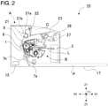
- FIG. 2 is a cross-sectional view of an apparatus main body A and a process cartridge (hereinafter described as a cartridge B) of an electrophotographic image forming apparatus 10.
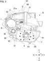
- FIG. 3 is a cross-sectional view of the cartridge B.
- the apparatus main body A is a portion excluding the cartridge B from the image forming apparatus.
- the image forming apparatus 10 shown in FIG. 2 is a laser beam printer in which the cartridge B is detachably attachable to the apparatus main body A.
- the apparatus main body A has an exposure apparatus 3 (laser scanner unit) used to form a latent image on a photosensitive drum 1 provided in the cartridge B when the cartridge B is mounted.
- an exposure apparatus 3 laser scanner unit
- a sheet tray 17 in which sheet materials P that are recording media on which an image is to be formed are accommodated is arranged under the cartridge B in the paper.
- the image forming apparatus 10 performs an image forming process on the sheet materials P on the basis of image information acquired by reception or the like from the outside of the apparatus.
- a pickup roller 7a In the apparatus main body A, a pickup roller 7a, a pair of feeding rollers 7b, a transfer roller 6, a transport guide 8, a fixing apparatus 21, a discharge roller 22, a discharge tray 23, and the like are also sequentially arranged along the transporting direction of the sheet materials P.
- the fixing apparatus 21 is constituted by a heat roller 21a and a pressurization roller 21b.
- the apparatus main body A further includes cartridge pressure members 27 and cartridge pressure springs 28 that will be described later.
- the cartridge B has the photosensitive drum 1 serving as an image bearing member, a charging roller 2 serving as a charging member, a developing unit 4 serving as a developing apparatus, and a cleaning unit 5 serving as cleaning means.
- the developing unit 4 has a developing roller 40 (developer bearing member) including a magnet roller 36, a developing container 41 in which toner T (developer) is accommodated and retained in a toner chamber 29, a transport member 43 serving also as a stirring member, and a developing blade 42.
- a cleaning unit 5 includes a cleaning frame body 51 including a waste toner chamber 51a or the like and a cleaning blade 52.
- a drive coupling 26 (see FIG. 6B ) of the apparatus main body A rotates. Since the drive coupling 26 engages the photosensitive drum 1 of the cartridge B, the photosensitive drum 1 also rotates at a prescribed peripheral speed (process speed) in an arrow R direction (see FIGS. 2 and 3 ) as the drive coupling 26 rotates. At this time, the charging roller 2 to which a bias voltage has been applied contacts the outer peripheral surface of the photosensitive drum 1 to uniformly charge the outer peripheral surface of the photosensitive drum 1 as shown in FIG. 3 .
- the exposure apparatus 3 of the apparatus main body A outputs laser light L according to image information with the control of the control unit 15.
- the laser light L performs scanning exposure on the outer peripheral surface of the photosensitive drum 1
- an electrostatic latent image corresponding to the image information is formed on the outer peripheral surface of the photosensitive drum 1.
- toner T accommodated in the toner chamber 29 of the developing unit 4 is stirred and transported by the rotation of the transport member 43 and delivered to a toner supply chamber 31.
- the toner T of the toner supply chamber 31 is born on the surface of the developing roller 40 by the magnetic force of the magnet roller 36 (stationary magnet).
- the developing blade 42 controls a layer thickness on the peripheral surface of the developing roller 40, while friction-charging the toner T born on the developing roller 40. Then, the toner T supplied to the photosensitive drum 1 develops an electrostatic latent image to be visualized as a toner image.
- the pickup roller 7a and the pair of feeding rollers 7b transport a sheet material P accommodated in the sheet tray 17 at the lower portion of the apparatus main body A to the transfer position between the photosensitive drum 1 and the transfer roller 6.
- a toner image on the photosensitive drum 1 is transferred onto the sheet material P at the transfer position.
- the sheet material P onto which the toner image has been transferred is separated from the photosensitive drum 1 and transported to the fixing apparatus 21 along the transport guide 8.
- the fixing apparatus 21 performs pressurization/heat fixation processing on the sheet material P passing through the nip portion between the heat roller 21a and the pressurization roller 21b to fix the toner image onto the sheet material P. Subsequently, the sheet material P is transported to the discharge roller 22 and discharged to the discharge tray 23.
- the cleaning blade 52 removes residual toner on the outer peripheral surface of the photosensitive drum 1 from which the toner image has been transferred and stores the removed residual toner in the waste toner chamber 51a as shown in FIG. 3 .
- the photosensitive drum 1 is used in an image forming process again.
- the charging roller 2, the developing roller 40, the transfer roller 6, and the cleaning blade 52 can be regarded as process means that acts on the photosensitive drum 1.
- FIG. 3 is a cross-sectional view of the cartridge B
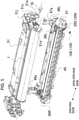
- FIGS. 4 and 5 are exploded perspective views for describing the configuration of the cartridge B. Note that screws used to connect respective components to each other will be omitted in the present embodiment.
- the cartridge B is discomposed into the cleaning unit 5 and the developing unit 4 to be shown.
- the cleaning unit 5 has the photosensitive drum 1, the charging roller 2, the cleaning blade 52, and a cleaning frame body 51 that supports the photosensitive drum 1, the charging roller 2, and the cleaning blade 52.
- a drum shaft 78 is press-fitted into a hole portion 73a (see FIG. 4 ) of a drum bearing 73.
- the drum shaft 78 is press-fitted into a hole portion 51c (see FIG. 5 ) provided on the cleaning frame body 51.
- the drum bearing 73 and the cleaning frame body 51 may be collectively called a cleaning frame body in a broad sense.
- the charging roller 2 and the cleaning blade 52 are arranged so as to contact the outer peripheral surface of the photosensitive drum 1.
- the charging roller 2 is brought into press-contact with the photosensitive drum 1 in a state in which a charging roller bearing 67 is pressurized by an urging member 68 toward the photosensitive drum 1.
- the charging roller 2 is driven to rotate by the rotation of the photosensitive drum 1.
- the developing unit 4 has the developing roller 40, the developing container 41 that supports the developing roller 40, the developing blade 42, and the like.
- the developing roller 40 is rotatably mounted on the developing container 41 by a driving-side developing bearing 46 (see FIG. 4 ) and a non-driving-side developing bearing 47 (see FIG. 5 ) that are provided at both ends.
- the non-driving-side developing bearing 47 of the present embodiment serves as a supporting body on which a memory mounting portion 200 is provided.
- a memory tag 100 serving as a memory member is mounted on the memory mounting portion 200.
- the magnet roller 36 is provided in the developing roller 40.
- the developing blade 42 used to control a toner layer on the developing roller 40 is arranged.
- interval retention members 38 (38R and 38L) are mounted at both ends of the developing roller 40. Since the interval retention members 38 contact the photosensitive drum 1, the developing roller 40 is retained with a slight gap produced between the developing roller 40 and the photosensitive drum 1.
- a procedure for connecting the developing unit 4 and the cleaning unit 5 to each other to constitute the cartridge B will be described.
- the center of a developing first supporting boss 46a of the driving-side developing bearing 46 corresponding to a first hanging hole 51i on the driving side of the cleaning frame body 51 and the center of a developing second supporting boss 47a of the non-driving-side developing bearing 47 corresponding to a second hanging hole 51j on the non-driving side thereof are aligned with each other.
- the developing unit 4 is moved in an arrow G direction
- the developing first supporting boss 46a and the developing second supporting boss 47a are fitted into the first hanging hole 51i and the second hanging hole 51j, respectively.
- the developing unit 4 is rotatably connected to the cleaning unit 5.
- the developing roller 40 is connected so as to be capable of contacting and separating from the photosensitive drum 1.
- the drum bearing 73 is mounted on the cleaning unit 5 to constitute the cartridge B.
- Developing urging members 48 (a non-driving-side developing urging member 48L and a driving-side developing urging member 48R) formed of compression springs urge the developing unit 4 to the cleaning unit 5 by an urging force.
- the interval retention members 38 provided at the developing roller 40 are brought into contact with the photosensitive drum 1.
- FIG. 6A is a perspective view of the apparatus main body A during the installation of the cartridge B when seen from a driving-side guide portion.
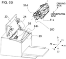
- FIG. 6B is a perspective view of the apparatus main body A during the installation of the cartridge B when seen from a non-driving-side guide portion.
- FIG. 7A is a cross-sectional view of the apparatus main body A during the positioning of the cartridge B when seen from the driving side.
- FIG. 7B is a cross-sectional view of the apparatus main body A during the positioning of the cartridge B when seen from the non-driving side.
- the installation direction of the cartridge B is a direction (as indicated by arrow C) substantially orthogonal to the axis line of the photosensitive drum 1.
- a driving-side plate 24 has a driving-side guide rail 24h serving as a guide (see FIG. 6B ), and a non-driving-side plate 25 has a non-driving-side upper guide rail 25d and a non-driving-side lower guide rail 25e (see FIG. 6A ).
- the drum bearing 73 provided on the driving side of the cartridge B is provided with a rotation stopped portion 73c (see FIGS. 4 , 6A , and 7A ).
- the cleaning frame body 51 has a positioned portion 51d and a rotation stopped portion 51e on the non-driving side in its longitudinal direction (see FIGS. 5 , 6B , and 7B ).
- the rotation stopped portion 73c on the driving side of the cartridge B inserted into the apparatus main body A is guided by the driving-side guide rail 24h of the apparatus main body A.
- the positioned portion 51d and the rotation stopped portion 51e on the non-driving side of the cartridge B are guided by the non-driving-side upper guide rail 25d and the non-driving-side lower guide rail 25e of the apparatus main body A, respectively.
- the driving-side plate 24 has an upper positioning portion 24a, a lower positioning portion 24b, and a rotation stopping portion 24c as a positioning mechanism.
- the drum bearing 73 has an upper positioned portion 73d and a lower positioned portion 73f.
- the non-driving-side plate 25 has a non-driving-side positioning portion 25a and a non-driving-side rotation stopping portion 25c.
- the cartridge pressure members 27 are rotatably mounted at both ends in the axial direction of the opening/closing door 30.
- the cartridge pressure springs 28 (28R and 28L) are, respectively, mounted at both ends in the longitudinal direction of a front plate 29 provided in the apparatus main body A.
- the drum bearing 73 has a pressed portion 73e serving as an urging force receiving portion, and the cleaning frame body 51 has a pressed portion 51o on the non-driving side.
- the cartridge B When the cartridge B receives a pressing force, the upper positioned portion 73d, the lower positioned portion 73f, and the rotation stopped portion 73c of the cartridge B are fixed to the upper positioning portion 24a, the lower positioning portion 24b, and the rotation stopping portion 24c of the apparatus main body A, respectively. Further, on the non-driving side, the positioned portion 51d and the rotation stopped portion 51e of the cartridge B are fixed to the non-driving-side positioning portion 25a and the non-driving-side rotation stopping portion 25c of the apparatus main body A, respectively. Thus, the cartridge B and the photosensitive drum 1 are positioned on both the driving side and the non-driving side.
- a configuration for positioning the cartridge B in the apparatus main body A is not limited to the above example.
- the opening/closing door 30 may directly tuck the cartridge B or a user may tuck the cartridge B without using the cartridge pressure members 27.
- the positions and the numbers of the positioning configurations on the side of the apparatus main body A and the positions and the numbers of the positioning configurations on the side of the cartridge B are not limited to the above example.
- the non-driving-side plate 25 of the apparatus main body A is provided with a tag connector 32 including an electric contact electrically connectable to the memory tag 100 at a position corresponding to the memory mounting portion 200 of the cartridge B.
- FIGS. 8A and 8B are enlarged perspective views showing the positioning configuration of the memory tag 100 provided in the cartridge B and the tag connector 32 provided in the apparatus main body A.
- the tag connector 32 is supported by the non-driving-side plate 25 and pressed in the direction of the cartridge B from the non-driving-side plate 25 by a connector spring 35.
- the tag connector 32 is provided with main-body electrode portions 33 capable of contacting contact portions 101 provided in the memory tag 100.
- the tag connector 32 is further provided with contact positioning portions 34 (34a and 34b) formed on both sides across the main-body electrode portions 33.
- the non-driving-side developing bearing 47 of the cartridge B is provided with the memory mounting portion 200 for mounting the memory tag 100.
- the memory mounting portion 200 positioning ribs 202a and 202b and lateral wall portions 200a and 200b are provided at positions opposing the contact positioning portions 34a and 34b of the tag connector 32 when the cartridge B is installed.
- the lateral wall portions 200a and 200b and the positioning ribs 202a and 202b engage the opposing contact positioning portions 34a and 34b, respectively.
- the cartridge B is positioned in the apparatus main body A.
- the contact portions 101 of the memory tag 100 contact the main-body electrode portions 33 of the tag connector 32 to establish electrical connection.
- the transmission and reception of information between the cartridge B and the apparatus main body A is made possible.
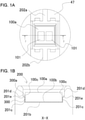
- FIG. 1A is a plan view of the memory mounting portion 200 before the memory tag 100 is mounted.
- FIG. 1B is a cross-sectional view of the memory mounting portion 200 in a state in which the memory tag 100 is fixed by adhesive 300.
- FIG. 9 is a perspective view of the memory tag 100.
- FIG. 10 is a perspective view of the memory mounting portion 200 before the memory tag 100 is mounted.
- FIGS. 11A and 11B are cross-sectional views showing the process of applying the adhesive 300 to mount the memory tag 100 on the memory mounting portion 200.
- the memory tag 100 includes a storage element that stores information relating to the cartridge B.
- the information includes, for example, the lot number of the cartridge, the characteristic information of the cartridge, the characteristic information of the image forming apparatus to which the cartridge is installed, or the like. By referring to these information items, it is possible to facilitate the maintenance of the apparatus main body A or the cartridge B.
- the memory tag 100 exemplified in FIG. 9 is a plate-shaped member that has a length of 5.5 mm and a width of 5 mm as the respective sides of an upper surface and has a thickness of 1.4 mm.
- the memory tag 100 includes a contact surface 100a (first surface), a bottom surface 100b (second surface) opposing the contact surface 100a, and four lateral surfaces 100c that extend in a direction crossing the contact surface 100a and the bottom surface 100b.
- the memory tag 100 is constituted by the two layers of a memory substrate 102 on which a storage element not shown is mounted and a protection portion 103 that is integrated with the memory substrate 102 and covers and protects the storage element.
- contact portions 101 electrically connected to the storage element are formed to be exposed.
- the shape of the memory tag 100 is not limited to a substantially cuboid shape.
- FIGS. 1A and 1B A configuration for mounting the memory tag 100 on the cartridge B will be specifically described with reference to FIGS. 1A and 1B , FIG. 5 , and FIG. 9 to FIGS. 11A and 11B .
- the memory mounting portion 200 for accommodating and fixing the memory tag 100 is formed as a substantially quadrangular depressed portion in a plan view at the prescribed position of the non-driving-side developing bearing 47 serving as the exterior portion of the cartridge B (see FIGS. 1A and 1B , FIG. 5 , and FIG. 10 ).
- the depressed portion of the memory mounting portion 200 is opened in a direction in which the cartridge is installed in the apparatus main body A.
- the depressed portion serves as an accommodation portion 201 that accommodates the memory tag 100.
- the accommodation portion 201 includes a bottom surface opposing portion 201b (first opposing portion) that opposes the bottom surface 100b when the memory tag 100 is accommodated.
- the accommodation portion 201 further includes lateral surface restriction portions 201c (second opposing portions), lateral surface buffer portions 201d, and inclination surfaces 201e (third opposing portions) that oppose the lateral surfaces 100c when the memory tag 100 is accommodated.
- a direction perpendicular to the surface of the bottom surface opposing portion 201b will be defined as a height direction and a distance from the surface of the bottom surface opposing portion 201b in the height direction will be defined as a height for the sake of convenience.
- the positions of the respective lateral surfaces 100c of the memory tag 100 are restricted by the lateral surface restriction portions 201c opposing the respective lateral surfaces 100c.
- a width Lb between the opposing lateral surface restriction portions 201c is therefore set to be slightly greater than a width Lmb of the memory tag 100 (Lb ⁇ Lmb).
- the memory tag 100 is fixed onto the memory mounting portion 200 via the adhesive 300.
- the adhesive 300 exists between the bottom surface 100b and the bottom surface opposing portion 201b and between the lateral surfaces 100c and the lateral surface restriction portions 201c.
- the adhesive 300 one having adequate bonding strength for the respective materials of the memory tag 100 and the memory mounting portion 200 is preferably used.
- a cyanoacrylate adhesive may be used.
- the types of the materials of the memory tag 100, the memory mounting portion 200, and the adhesive 300 are not limited to the above materials.
- the adhesive 300 is first applied onto the accommodation portion 201 as shown in FIG. 11A .
- the memory tag 100 is inserted into the accommodation portion 201 as shown in FIG. 11B .
- the adhesive 300 is pressed and expanded by the memory tag 100 and spread between the bottom surface 100b of the memory tag and the bottom surface opposing portion 201b.
- the pressed and expanded adhesive 300 is further spread at least between the lateral surfaces 100c and the lateral surface restriction portions 201c.
- FIG. 1B shows a state in which the insertion of the memory tag 100 is completed.
- a plurality of surfaces here, the bottom surface 100b and at least the range of the lateral surfaces 100c opposing the lateral surface restriction portions 201c
- the memory tag 100 is bonded onto the memory mounting portion 200.
- the adhesive 300 when the adhesive 300 is applied by such an amount that the height of the upper surface 300a of the adhesive 300 becomes lower than that of the contact surface 100a, the adhesive 300 is prevented from adhering to the contact surface 100a. Accordingly, it is possible to secure the electrical connection between the main-body electrode portions 33 of the tag connector 32 and the contact portions 101 of the memory tag 100.
- the lateral surface buffer portions 201d and the inclination surfaces 201e are provided at regions closer to the contact surface 100a than the lateral surface restriction portions 201c as shown in FIG. 1B . These portions are positioned at places more distant from the memory tag 100 than the lateral surface restriction portions 201c. Accordingly, compared with a case in which the lateral surface buffer portions 201d and the inclination surfaces 201e are not provided (that is, a case in which the lateral surfaces 100c and opposing surfaces are parallel to each other), it is possible to increase the volume of the space between the memory tag 100 and the accommodation portion 201 in which the adhesive 300 is accommodatable.
- the height of a portion at which the inclination surfaces 201e and the lateral surface buffer portions 201d are connected to each other is set to be lower than that of the contact surface 100a, whereby it is possible to accelerate timing at which the buffer region between the lateral surface buffer portions 201d and the lateral surfaces 100c produces a buffer effect.
- the upper surface 300a of the adhesive 300 in the respective cartridges B preferably has a prescribed height.
- the height of the upper surface 300a fluctuates since the application amount of the adhesive 300 slightly fluctuates. Therefore, by providing the lateral surface buffer portions 201d and the inclination surfaces 201e in the accommodation portion 201 as in the present embodiment, it is possible to reduce a fluctuation in the height of the upper surface 300a even if the application amount of the adhesive 300 fluctuates.
- the memory tag 100 is put in the lateral surface restriction portions 201c along the inclination surfaces 201e even if the memory tag 100 contacts the accommodation portion 201 when the memory tag 100 is inserted into the accommodation portion 201.
- the bottom surface 100b adheres closely to the bottom surface opposing portion 201b, it is possible to reliably mount the memory tag 100 on the memory mounting portion 200.
- the present embodiment it is possible to firmly fix the memory tag 100 onto the memory mounting portion 200 by the adhesive 300 and prevent the memory tag from falling off the memory mounting portion. In addition, it is possible to reduce a fluctuation in the height of the upper surface 300a of the adhesive 300. In addition, it is possible to smoothly mount the memory tag 100 on the memory mounting portion 200.
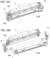
- FIGS. 12A and 12B show a cartridge B including a photosensitive drum 1, a charging unit 1002 serving as a charging apparatus, and a developing unit 4 serving as a developing apparatus.
- the cartridge B rotatably supports the photosensitive drum 1 and the developing unit 4 with a driving-side drum bearing 73 and a non-driving-side drum bearing 74.
- a memory mounting portion 200 is provided at the non-driving-side drum bearing 74 in the example shown in FIGS. 12A and 12B but may be provided at the driving-side drum bearing 73, the charging unit 1002, or the developing unit 4.
- the memory tag mounting configuration of the present embodiment is also applicable to a cartridge other than a process cartridge.
- examples of other cartridges include a drum cartridge having a photosensitive drum and a developing cartridge including a developer bearing member for supplying developer to an image bearing member on which a toner image is formed and a developer accommodation portion accommodating the developer.
- examples of other cartridges include a developer cartridge accommodating developer and an inkjet cartridge accommodating ink used in an inkjet recording apparatus.
- the present invention is applicable in a case in which a memory tag is mounted on a cartridge detachably attachable to the apparatus main body of an image forming apparatus.
- FIGS. 13A to 13C show the behavior of the adhesive 1300 when the memory tag 100 is inserted into the accommodation portion 1201 to which the adhesive 1300 is applied.
- FIG. 13A shows a state immediately after the memory tag 100 is mounted.
- FIG. 13B is a cross-sectional view taken along the line K-K in FIG. 13A and shows a state in which the adhesive 1300 is lenticulated as a result of the mounting of the memory tag 100.
- FIG. 13C is also a cross-sectional view taken along the line K-K in FIG. 13A and shows a state in which the adhesive is scattered as a result of the mounting of the memory tag.
- the adhesive 1300 When the memory tag 100 is inserted into the accommodation portion 1201 to which the adhesive 1300 is applied, the adhesive 1300 is pressed and expanded to the memory tag 100.
- the adhesive 1300 has low viscosity (for example, about 2 mpa ⁇ s)
- lenticulation 1301 is likely to occur in the pressed and expanded adhesive 1300 as shown in FIG. 13B .
- the lenticulated adhesive 1300 sometimes rebounds after hitting a lateral surface buffer portion 1201d, runs on a contact surface 100a of the memory tag 100, and adheres to contact portions 101.
- the adhesive extruded by the memory tag 100 sometimes flies out as a droplet 1302 as shown in FIG. 13C .
- the adhesive 1300 adheres to the contact portions 101 of the contact surface 100a or scatters to the outside of an accommodation portion.
- the adhesive 1300 having low viscosity when used under the configuration of the first embodiment, there is a need to accurately manage the application amount of the adhesive 1300 and prevent the lenticulated adhesive 1300 from running on the contact surface 100a. Further, there is a need to decrease the mounting speed of the memory tag 100 to reduce the scattering of the adhesive 1300.
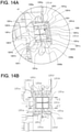
- FIG. 14A is a perspective view of the vicinity of a memory mounting portion.
- FIG. 14B is a view of the vicinity of the memory mounting portion when seen from the front side of a bottom surface opposing portion.
- FIG. 15A is a cross-sectional view of the vicinity of the memory mounting portion when seen from the KX-KX cross-section and the KY-KY cross section of FIG. 14B .
- FIG. 15B is a cross-sectional view of the vicinity of the memory mounting portion when seen from the KZ-KZ cross section of FIG. 14B .
- the memory tag 100 is accommodated in a memory mounting portion 1200 and fixed by the adhesive 1300 to be mounted on the cartridge B. Further, the memory mounting portion 1200 of the present embodiment is also provided at a non-driving-side developing bearing 47 serving as the exterior portion of the cartridge B as a substantially quadrangular depressed portion having its one end opened.
- the depressed portion is constituted as the accommodation portion 1201.
- the accommodation portion 1201 includes a bottom surface opposing portion 1201b (first opposing portion) opposing a bottom surface 100b of the memory tag 100 and lateral surface restriction portions 1201c (second opposing portions) opposing lateral surfaces 100c.
- the bottom surface opposing portion 1201b of the present embodiment is provided with a flow path groove 1201f.
- the flow path groove 1201f includes a quadrangular-shaped portion and a cross-shaped portion.
- the quadrangular-shaped portion is a portion that corresponds to the connected portion between the bottom surface opposing portion 1201b and the lateral surface restriction portions 1201c and is obtained by connecting the four outsides of the bottom surface opposing portion 1201b to each other.
- the cross-shaped portion is provided at the center of the bottom surface opposing portion 1201b.
- the cross-shaped groove and the quadrangular-shaped groove are preferably connected to each other. By the existence of the flow path groove 1201f, the adhesive 1300 evenly sneaks to the entire surface of the bottom surface opposing portion 1201b when the adhesive 1300 is applied.
- the shape of the flow path groove 1201f is not limited to the example shown in FIGS. 14A and 14B and FIGS. 15A and 15B but may only be a shape enabling the diffusion of the adhesive 1300.
- the arrangement or shape of the flow path groove 1201f is appropriately designed according to the type of the adhesive 1300, the application condition of the adhesive 1300, the materials or sizes of both members bonded to each other, required bonding strength, or the like.
- the shape of the flow path groove 1201f is not limited to a cross shape including crosswise grooves at the central portion of the bottom surface opposing portion 1201b.
- the number of grooves in a lengthwise direction and/or a widthwise direction may be increased, or grooves in an oblique direction may be added.
- the flow path groove 1201f may be provided only at the central portion of the bottom surface opposing portion 1201b.
- the shape is not limited to a cross shape. As opposed to this, only the flow path groove 1201f surrounding the bottom surface opposing portion 1201b may be provided.
- lateral surface buffer portions 1201d, accumulation groove portions 1201g, slant portions 1201e, and overflow step portions 1201h are further provided at positions more distant from the bottom surface opposing portion 1201b than the lateral surface restriction portions 1201c.
- the height of the lateral surface restriction portions 1201c in its direction perpendicular to a surface forming the bottom surface opposing portion 1201b is set to fall within a range not greater than the thickness of the memory tag. By setting such a height, it is possible to prevent the adhesive 1300 from rebounding after hitting the lateral surface restriction portions 1201c when the memory tag 100 is inserted.
- the lateral surface restriction portions 1201c are set to have a height of 0.8 mm (see FIG. 17B ) relative to the thickness of the memory tag, 1.4 mm.
- the accumulation groove portions 1201g are groove-shaped portions formed at positions lower than the apexes of the lateral surface restriction portions 1201c in their direction perpendicular to the surface forming the bottom surface opposing portion 1201b.
- the accumulation groove portions 1201g are provided at two right and left spots that are parts of the four sides of the bottom surface opposing portion 1201b as shown in FIG. 15B .
- the accumulation groove portions 1201g may be provided at three spots so as to correspond to three sides of the bottom surface opposing portion 1201b, or may be arranged at four spots so as to surround the bottom surface opposing portion 1201b in all directions.
- the lateral surface buffer portions 1201d are provided at positions more distant from the bottom surface opposing portion 1201b than the lateral surface restriction portions 1201c so as to surround the lateral surface restriction portions 1201c in all directions. About the spots at which the accumulation groove portions 1201g are provided, the lateral surface buffer portions 1201d are provided at positions more distant from the bottom surface opposing portion 1201b than the accumulation groove portions 1201g. It can be said that the lateral surface buffer portions 1201d generally define the outermost periphery of the entire accommodation portion 1201.
- the upper surfaces of the lateral surface restriction portions 1201c are called lateral-surface restriction upper surface portions 1201i.
- the slant portions 1201e and the overflow step portions 1201h are provided on the lateral-surface restriction upper surface portions 1201i.
- the overflow step portions 1201h are provided so as to connect the lateral surface restriction portions 1201c and the accumulation groove portions 1201g to each other.
- the height of the overflow step portions 1201h is lower than that of the lateral-surface restriction upper surface portions 1201i and higher than those of the accumulation groove portions 1201g and the bottom surface opposing portion 1201b in a direction perpendicular to the surface of the bottom surface opposing portion 1201b.
- the slant portions 1201e have a slant shape that is lower on its side close to the lateral surface restriction portions 1201c and higher on its side close to the accumulation groove portions 1201g in the direction perpendicular to the surface of the bottom surface opposing portion 1201b of the lateral surface restriction portions 1201c.
- the slant portions 1201e play a role in luring the memory tag 100 when the memory tag 100 is mounted.
- FIG. 16A shows a state in which the adhesive 1300 circulates around the entire region of the memory mounting portion 1200 during the application of the adhesive 1300.
- FIG. 16B is a cross-sectional view showing a state in which the memory tag 100 is inserted into the accommodation portion 1201 while being lured into the slant portions 1201e.
- FIG. 17A shows the process of inserting the memory tag 100 into the accommodation portion 1201.
- FIG. 17B is a cross-sectional view of the accommodation portion 1201 when seen from the SB-SB cross section of FIG. 17A and shows the flow of the adhesive 1300 when the memory tag 100 is inserted into the accommodation portion 1201.
- FIG. 18A is a cross-sectional view of the accommodation portion 1201 when seen from the SA-SA cross section of FIG. 17A and shows the flow of the adhesive 1300 when the memory tag 100 is inserted into the accommodation portion 1201.
- FIG. 18B is a cross-sectional view showing a state in which the mounting of the memory tag 100 is completed.
- the adhesive 1300 is applied onto the accommodation portion 1201 of the memory mounting portion 1200.
- the adhesive 1300 is applied in the vicinity of the center of the bottom surface opposing portion 1201b.
- a cyanoacrylate adhesive having a viscosity of about 2 mpa ⁇ s
- the adhesive 1300 is used as the adhesive 1300.
- the applied adhesive 1300 circulates around the surface of the bottom surface opposing portion 1201b along the flow path grooves 1201f provided in a cross shape at the center of the bottom surface opposing portion 1201b (as indicated by arrows Ya in FIG. 16A ) and then moves along the flow path grooves 1201f on the four outer sides of the bottom surface opposing portion 1201b.
- the adhesive 1300 evenly circulates around the entire region of the bottom surface opposing portion 1201b. Accordingly, since it is possible to reduce unevenness in the wraparound of the adhesive 1300 when the memory tag 100 is mounted later, the bonding and fixation of the memory tag 100 is secured. In addition, it is also possible to prevent the overflow of the adhesive 1300 due to the unevenness of the adhesive 1300.
- the configuration of the present embodiment is also applicable to a case in which the application amount of the adhesive 1300 fluctuates within the surface of the adhesive 1300 and the adhesive 1300 partially overflows. That is, the overflowing adhesive 1300 flows into the accumulation groove portions 1201g along the overflow step portions 1201h lower in height than the lateral-surface restriction upper surface portions 1201i (as indicated by arrows Yb in FIG. 16A ).
- the memory tag 100 is inserted into the accommodation portion 1201 (as indicated by an arrow F). Even if the center of the memory tag 100 is slightly deviated from the center of the bottom surface opposing portion 1201b at this time, the memory tag 100 moves while sliding in the direction of an arrow S under the existence of the slant portions 1201e and is inserted into the accommodation portion 1201. That is, it is possible to absorb a positioning fluctuation during the mounting of the memory tag 100 on the accommodation portion 1201.
- the adhesive 1300 is pressed and expanded by the memory tag 100 when the insertion of the memory tag 100 into the accommodation portion 1201 is completed. At this time, the adhesive 1300 spreads between the bottom surface 100b and the bottom surface opposing portion 1201a and between the lateral surface 100c and at least the lateral surface restriction portions 1201c. Thus, the adhesive 1300 is arranged at a portion needed to fix the memory tag 100.
- the surplus adhesive 1300 that overflows after being pressed and expanded by the memory tag 100 gets over the lateral-surface restriction upper surface portions 1201i and flows out in the direction of the lateral surface buffer portions 1201d.
- the overflowing surplus adhesive 1300 runs down the accumulation groove portions 1201g before hitting the lateral walls of the lateral surface buffer portions 1201d with the provision of the accumulation groove portions 1201g (as indicated by arrows Yc in FIG. 17B ), it is possible to prevent the lenticulation of the adhesive 1300.
- the overflow step portions 1201h lower in height than the lateral-surface restriction upper surface portions 1201i are provided at both ends of sides on which the accumulation groove portions 1201g are not provided. Therefore, the overflowing adhesive 1300 flows into the accumulation groove portions 1201g along the overflow step portions 1201h (as indicated by arrows Yd in FIG. 18A ).
- a plurality of surfaces (the bottom surface 100b and the range of the lateral surfaces 100c that oppose at least the lateral surface restriction portions 1201c) of the memory tag 100 are bonded.
- the positions of the respective lateral surfaces 100c of the memory tag 100 are restricted by the opposing lateral surface restriction portions 1201c in the accommodation portion 1201. Therefore, in order to make main-body electrode portions 33 of an apparatus main body A reliably contact portions 101 of the memory tag 100 to enable information communication in the present embodiment as well, the width between the opposing lateral surface restriction portions 1201c may only be slightly greater than that of the memory tag 100.
- the above configuration makes it possible to cause the surplus adhesive 1300 overflowing during the application of the adhesive 1300 or during the mounting of the memory tag 100 to positively flow into the accumulation groove portions 1201g. Therefore, it is possible to prevent the lenticulation of the adhesive 1300 or prevent the overflow of the adhesive 1300 to the contact surface 100a of the memory tag 100. As a result, it is possible to prevent the overflowing surplus adhesive 1300 from adhering to the contact portions 101 of the contact surface 100a of the memory tag 100 or prevent the same from scattering to the accommodation portion 1201 or the outside of the cartridge B. Accordingly, it is possible to stably secure the electrical connection between the main-body electrode portions 33 of the tag connector 32 and the contact portions 101 of the memory tag 100.
- the above configuration makes it possible to prevent the lenticulation of the adhesive 1300 or prevent the adhesive 1300 from scattering to the contact portions 101 of the contact surface 100a of the memory tag 100 during the mounting of the memory tag 100. Therefore, it is possible to further prevent a fluctuation in the application of the adhesive 1300 during the mounting and stably mount the memory tag 100. Further, since scattering is not likely to occur even if the mounting speed of the memory tag 100 is increased, productivity is improved.
- the installation place of the memory mounting portion 1200 is provided at the non-driving-side developing bearing 47 of the developing unit 4 but is not limited to this.
- the configuration of the present embodiment is also applicable to a cartridge B that is the same as the one described using FIGS. 12A and 12B in the modified examples of the first embodiment.
- the present embodiment is the same as the first embodiment in that the configuration of the memory mounting portion 1200 is also applicable to a cartridge other than a process cartridge or an image forming apparatus other than an electrophotographic image forming apparatus.
- a cartridge attachable to an image forming apparatus body including: a memory member storing information relating to the cartridge; and a supporting body having a memory mounting portion on which the memory member is mounted, the memory member having a first surface, a second surface, and a lateral surface, the first surface is provided with a contact portion connected to a body electrode portion of the body of the image forming apparatus when the cartridge is installed in the body of the image forming apparatus, the memory mounting portion has a first opposing portion opposing the second surface and a second opposing portion opposing the lateral surface when the memory member is mounted, the memory member is mounted by adhesive between the second surface and the first opposing portion and between the lateral surface and the second opposing portion.
Landscapes
- Physics & Mathematics (AREA)
- General Physics & Mathematics (AREA)
- Engineering & Computer Science (AREA)
- Computer Vision & Pattern Recognition (AREA)
- Computer Networks & Wireless Communication (AREA)
- Electrophotography Configuration And Component (AREA)
- Dry Development In Electrophotography (AREA)
Abstract
Description
- The present invention relates to a cartridge and an image forming apparatus.
- Conventionally, image forming apparatuses that form images on sheet-shaped recording media such as papers according to an electrophotographic system or the like have been known. Examples of the image forming apparatuses include copiers, facsimile machines, printers (such as laser beam printers and LED printers), and their multi-function machines (multi-function printers).
- Among such image forming apparatuses, image forming apparatuses of a cartridge type have been known. A cartridge is a unit detachably attachable to an image forming apparatus and is, for example, a process cartridge. The process cartridge includes a photosensitive member, process means (such as a charging member, a developing member, and a cleaning member) acting on the photosensitive member, or the like. By the use of the cartridge, a developer replenishing operation for the image forming apparatus or the maintenance of various process means is facilitated. That is, the photosensitive member, the charging member, the developing member, the cleaning member, and the like are collectively made into a cartridge inside a frame body, and the cartridge is made detachably attachable to the main body of the image forming apparatus. Thus, since a user himself/herself is allowed to conduct the maintenance of the apparatus through the replacement of the cartridge, operability is improved.
- Some cartridges have a memory such as IC memory mounted thereon and enable the transmission and reception of information between the main body of an apparatus and the cartridges when the cartridges are mounted on the main body of the apparatus. Examples of information stored in the memory mounted on the cartridges include the lot numbers of the cartridges, the characteristics of the image forming apparatus, and the characteristics of process means. Thus, the maintenance of the main body of the apparatus or the cartridges is facilitated. In addition, the control of image formation according to information stored in the memory makes it possible to perform the image formation under optimum conditions.
-
Japanese Patent Application Laid-open No. 2014-102506 - There has been demanded a method for more reliably preventing a memory from falling off when the memory is provided in the cartridge of an image forming apparatus.
- The present invention has been made in view of the above problem and the present invention is developed for providing a technology for preventing a memory provided in a cartridge installed in an image forming apparatus from falling off.
- The present invention in its first aspect provides a cartridge as specified in
claims 1 to 16. - The present invention in its second aspect provides an image forming apparatus as specified in
claim 17. - According to the present invention, it is possible to provide a technology for preventing a memory provided in a cartridge installed in an image forming apparatus from falling off.
- Further features of the present invention will become apparent from the following description of exemplary embodiments with reference to the attached drawings.
-
-
FIGS. 1A and 1B are cross-sectional views of a memory mounting portion in which a memory member is accommodated; -
FIG. 2 is a schematic cross-sectional view of an image forming apparatus; -
FIG. 3 is a schematic cross-sectional view of a cartridge; -
FIG. 4 is an exploded perspective view showing the driving side of the cartridge; -
FIG. 5 is an exploded perspective view showing the non-driving side of the cartridge; -
FIG. 6A is a view describing the installation of the cartridge; -
FIG. 6B is a view describing the installation of the cartridge; -
FIGS. 7A and 7B are cross-sectional views describing a cartridge installation process; -
FIGS. 8A and 8B are views describing the contacts of a memory member; -
FIG. 9 is a perspective view of the memory member; -
FIG. 10 is a perspective view of the memory mounting portion; -
FIGS. 11A and 11B are cross-sectional views describing the mounting of the memory member on the memory mounting portion; -
FIGS. 12A and 12B are perspective views showing the position of a memory mounting portion in a cartridge according to a modified example; -
FIGS. 13A to 13C are views describing the state of adhesive after the mounting of a conventional memory tag; -
FIGS. 14A and 14B are views showing the vicinity of a memory mounting portion according to a second embodiment; -
FIGS. 15A and 15B are cross-sectional views of the vicinity of the memory mounting portion according to the second embodiment; -
FIGS. 16A and 16B are views describing the state of mounting a memory tag according to the second embodiment; -
FIGS. 17A and 17B are views describing the insertion of the memory tag according to the second embodiment; and -
FIGS. 18A and 18B are cross-sectional views describing the mounting of the memory tag on an accommodation portion according to the second embodiment. - Hereinafter, modes for carrying out the present invention will be exemplarily described in detail with reference to the drawings and embodiments. However, the functions, materials, dimensions, shapes, their relative arrangements, or the like of constituting components described in the embodiments will not intend to limit the scope of the present invention unless otherwise specifically noted. Further, the functions, materials, dimensions, shapes, their relative arrangements, or the like of members once described in the following description will be the same as those initially described unless otherwise particularly noted.
- In the following description, a laser beam printer will be exemplified as an electrophotographic image forming apparatus, and a process cartridge used in the laser beam printer will be exemplified as a cartridge. The present invention may be grasped as an invention relating to a cartridge on which a memory member is mountable, or may be an invention relating to an image forming apparatus including the cartridge and the main body of an image forming apparatus. Further, the present invention may be grasped as a method for manufacturing the cartridge or a method for manufacturing the image forming apparatus, the method including a step of mounting a memory member on the cartridge.
- Note that in the following description, the longitudinal direction of the cartridge will be the rotational axis direction of an electrophotographic photosensitive drum and will be a direction substantially orthogonal to a direction in which the cartridge is attached to and detached from the main body of the image forming apparatus. Further, in the longitudinal direction, a side on which the photosensitive drum receives a driving force from the main body of the image forming apparatus is defined as a driving side, and the side opposite to the driving side is defined as a non-driving side. The "front side" of the image forming apparatus is defined as a direction in which the driving side is positioned on the right and the non-driving side is positioned on the left when the main body of the image forming apparatus is seen from the front side.
- First, the entire configuration and image forming process of a first embodiment will be described.
FIG. 2 is a cross-sectional view of an apparatus main body A and a process cartridge (hereinafter described as a cartridge B) of an electrophotographicimage forming apparatus 10.FIG. 3 is a cross-sectional view of the cartridge B. Here, the apparatus main body A is a portion excluding the cartridge B from the image forming apparatus. - The
image forming apparatus 10 shown inFIG. 2 is a laser beam printer in which the cartridge B is detachably attachable to the apparatus main body A. The apparatus main body A has an exposure apparatus 3 (laser scanner unit) used to form a latent image on aphotosensitive drum 1 provided in the cartridge B when the cartridge B is mounted. Further, asheet tray 17 in which sheet materials P that are recording media on which an image is to be formed are accommodated is arranged under the cartridge B in the paper. - According to the control of a
control unit 15, theimage forming apparatus 10 performs an image forming process on the sheet materials P on the basis of image information acquired by reception or the like from the outside of the apparatus. - In the apparatus main body A, a
pickup roller 7a, a pair of feedingrollers 7b, atransfer roller 6, atransport guide 8, a fixingapparatus 21, adischarge roller 22, adischarge tray 23, and the like are also sequentially arranged along the transporting direction of the sheet materials P. The fixingapparatus 21 is constituted by aheat roller 21a and apressurization roller 21b. The apparatus main body A further includescartridge pressure members 27 and cartridge pressure springs 28 that will be described later. - The cartridge B has the
photosensitive drum 1 serving as an image bearing member, a chargingroller 2 serving as a charging member, a developingunit 4 serving as a developing apparatus, and acleaning unit 5 serving as cleaning means. The developingunit 4 has a developing roller 40 (developer bearing member) including amagnet roller 36, a developingcontainer 41 in which toner T (developer) is accommodated and retained in atoner chamber 29, atransport member 43 serving also as a stirring member, and a developingblade 42. Acleaning unit 5 includes acleaning frame body 51 including awaste toner chamber 51a or the like and acleaning blade 52. - Next, the image forming process will be described. On the basis of the print start signal of the
control unit 15, a drive coupling 26 (seeFIG. 6B ) of the apparatus main body A rotates. Since thedrive coupling 26 engages thephotosensitive drum 1 of the cartridge B, thephotosensitive drum 1 also rotates at a prescribed peripheral speed (process speed) in an arrow R direction (seeFIGS. 2 and3 ) as thedrive coupling 26 rotates. At this time, the chargingroller 2 to which a bias voltage has been applied contacts the outer peripheral surface of thephotosensitive drum 1 to uniformly charge the outer peripheral surface of thephotosensitive drum 1 as shown inFIG. 3 . - The
exposure apparatus 3 of the apparatus main body A outputs laser light L according to image information with the control of thecontrol unit 15. When the laser light L performs scanning exposure on the outer peripheral surface of thephotosensitive drum 1, an electrostatic latent image corresponding to the image information is formed on the outer peripheral surface of thephotosensitive drum 1. - On the other hand, toner T accommodated in the
toner chamber 29 of the developingunit 4 is stirred and transported by the rotation of thetransport member 43 and delivered to atoner supply chamber 31. The toner T of thetoner supply chamber 31 is born on the surface of the developingroller 40 by the magnetic force of the magnet roller 36 (stationary magnet). The developingblade 42 controls a layer thickness on the peripheral surface of the developingroller 40, while friction-charging the toner T born on the developingroller 40. Then, the toner T supplied to thephotosensitive drum 1 develops an electrostatic latent image to be visualized as a toner image. - Further, in conjunction with the output timing of the laser light L, the
pickup roller 7a and the pair of feedingrollers 7b transport a sheet material P accommodated in thesheet tray 17 at the lower portion of the apparatus main body A to the transfer position between thephotosensitive drum 1 and thetransfer roller 6. A toner image on thephotosensitive drum 1 is transferred onto the sheet material P at the transfer position. The sheet material P onto which the toner image has been transferred is separated from thephotosensitive drum 1 and transported to the fixingapparatus 21 along thetransport guide 8. The fixingapparatus 21 performs pressurization/heat fixation processing on the sheet material P passing through the nip portion between theheat roller 21a and thepressurization roller 21b to fix the toner image onto the sheet material P. Subsequently, the sheet material P is transported to thedischarge roller 22 and discharged to thedischarge tray 23. - On the other hand, the
cleaning blade 52 removes residual toner on the outer peripheral surface of thephotosensitive drum 1 from which the toner image has been transferred and stores the removed residual toner in thewaste toner chamber 51a as shown inFIG. 3 . After that, thephotosensitive drum 1 is used in an image forming process again. In the above process, the chargingroller 2, the developingroller 40, thetransfer roller 6, and thecleaning blade 52 can be regarded as process means that acts on thephotosensitive drum 1. - Next, the entire configuration of the cartridge B will be described.
FIG. 3 is a cross-sectional view of the cartridge B, andFIGS. 4 and5 are exploded perspective views for describing the configuration of the cartridge B. Note that screws used to connect respective components to each other will be omitted in the present embodiment. - In
FIGS. 4 and5 , the cartridge B is discomposed into thecleaning unit 5 and the developingunit 4 to be shown. Thecleaning unit 5 has thephotosensitive drum 1, the chargingroller 2, thecleaning blade 52, and acleaning frame body 51 that supports thephotosensitive drum 1, the chargingroller 2, and thecleaning blade 52. On the driving side of thephotosensitive drum 1, adrum shaft 78 is press-fitted into ahole portion 73a (seeFIG. 4 ) of adrum bearing 73. Further, on the non-driving side of thephotosensitive drum 1, thedrum shaft 78 is press-fitted into ahole portion 51c (seeFIG. 5 ) provided on thecleaning frame body 51. Thus, thephotosensitive drum 1 is rotatably supported. Note that the drum bearing 73 and thecleaning frame body 51 may be collectively called a cleaning frame body in a broad sense. - As shown in
FIG. 3 , the chargingroller 2 and thecleaning blade 52 are arranged so as to contact the outer peripheral surface of thephotosensitive drum 1. The chargingroller 2 is brought into press-contact with thephotosensitive drum 1 in a state in which a chargingroller bearing 67 is pressurized by an urgingmember 68 toward thephotosensitive drum 1. The chargingroller 2 is driven to rotate by the rotation of thephotosensitive drum 1. - The developing
unit 4 has the developingroller 40, the developingcontainer 41 that supports the developingroller 40, the developingblade 42, and the like. The developingroller 40 is rotatably mounted on the developingcontainer 41 by a driving-side developing bearing 46 (seeFIG. 4 ) and a non-driving-side developing bearing 47 (seeFIG. 5 ) that are provided at both ends. Further, the non-driving-side developing bearing 47 of the present embodiment serves as a supporting body on which amemory mounting portion 200 is provided. On thememory mounting portion 200, amemory tag 100 serving as a memory member is mounted. - Further, the
magnet roller 36 is provided in the developingroller 40. In the developingunit 4, the developingblade 42 used to control a toner layer on the developingroller 40 is arranged. As shown inFIG. 5 , interval retention members 38 (38R and 38L) are mounted at both ends of the developingroller 40. Since the interval retention members 38 contact thephotosensitive drum 1, the developingroller 40 is retained with a slight gap produced between the developingroller 40 and thephotosensitive drum 1. - A procedure for connecting the developing
unit 4 and thecleaning unit 5 to each other to constitute the cartridge B will be described. First, the center of a developing first supportingboss 46a of the driving-side developing bearing 46 corresponding to afirst hanging hole 51i on the driving side of thecleaning frame body 51 and the center of a developing second supportingboss 47a of the non-driving-side developing bearing 47 corresponding to asecond hanging hole 51j on the non-driving side thereof are aligned with each other. Specifically, when the developingunit 4 is moved in an arrow G direction, the developing first supportingboss 46a and the developing second supportingboss 47a are fitted into thefirst hanging hole 51i and thesecond hanging hole 51j, respectively. Thus, the developingunit 4 is rotatably connected to thecleaning unit 5. As a result, the developingroller 40 is connected so as to be capable of contacting and separating from thephotosensitive drum 1. After that, the drum bearing 73 is mounted on thecleaning unit 5 to constitute the cartridge B. - Developing urging members 48 (a non-driving-side developing urging
member 48L and a driving-side developing urgingmember 48R) formed of compression springs urge the developingunit 4 to thecleaning unit 5 by an urging force. Thus, the interval retention members 38 provided at the developingroller 40 are brought into contact with thephotosensitive drum 1. - Next, the installation of the cartridge B will be described using
FIGS. 6A ,6B ,7A, and 7B .FIG. 6A is a perspective view of the apparatus main body A during the installation of the cartridge B when seen from a driving-side guide portion.FIG. 6B is a perspective view of the apparatus main body A during the installation of the cartridge B when seen from a non-driving-side guide portion.FIG. 7A is a cross-sectional view of the apparatus main body A during the positioning of the cartridge B when seen from the driving side.FIG. 7B is a cross-sectional view of the apparatus main body A during the positioning of the cartridge B when seen from the non-driving side. - As shown in
FIG. 6A , the installation direction of the cartridge B is a direction (as indicated by arrow C) substantially orthogonal to the axis line of thephotosensitive drum 1. A driving-side plate 24 has a driving-side guide rail 24h serving as a guide (seeFIG. 6B ), and a non-driving-side plate 25 has a non-driving-sideupper guide rail 25d and a non-driving-sidelower guide rail 25e (seeFIG. 6A ). - Further, the drum bearing 73 provided on the driving side of the cartridge B is provided with a rotation stopped
portion 73c (seeFIGS. 4 ,6A , and7A ). Further, thecleaning frame body 51 has a positionedportion 51d and a rotation stoppedportion 51e on the non-driving side in its longitudinal direction (seeFIGS. 5 ,6B , and7B ). - The rotation stopped
portion 73c on the driving side of the cartridge B inserted into the apparatus main body A is guided by the driving-side guide rail 24h of the apparatus main body A. At the same time, the positionedportion 51d and the rotation stoppedportion 51e on the non-driving side of the cartridge B are guided by the non-driving-sideupper guide rail 25d and the non-driving-sidelower guide rail 25e of the apparatus main body A, respectively. - Next, a state in which an opening/closing
door 30 is closed will be described. As shown inFIG. 7A , the driving-side plate 24 has anupper positioning portion 24a, alower positioning portion 24b, and arotation stopping portion 24c as a positioning mechanism. Further, the drum bearing 73 has an upper positionedportion 73d and a lower positionedportion 73f. In addition, as shown inFIG. 7B , the non-driving-side plate 25 has a non-driving-side positioning portion 25a and a non-driving-siderotation stopping portion 25c. - Further, the cartridge pressure members 27 (27R and 27L) are rotatably mounted at both ends in the axial direction of the opening/closing
door 30. The cartridge pressure springs 28 (28R and 28L) are, respectively, mounted at both ends in the longitudinal direction of afront plate 29 provided in the apparatus main body A. Thedrum bearing 73 has a pressedportion 73e serving as an urging force receiving portion, and thecleaning frame body 51 has a pressed portion 51o on the non-driving side. When the opening/closingdoor 30 is closed, the pressedportions 73e and 51o of the cartridge B are pressed by the cartridge pressure members 27 (27R and 27L) urged by the cartridge pressure springs 28 (28R and 28L) of the apparatus main body A. - When the cartridge B receives a pressing force, the upper positioned
portion 73d, the lower positionedportion 73f, and the rotation stoppedportion 73c of the cartridge B are fixed to theupper positioning portion 24a, thelower positioning portion 24b, and therotation stopping portion 24c of the apparatus main body A, respectively. Further, on the non-driving side, the positionedportion 51d and the rotation stoppedportion 51e of the cartridge B are fixed to the non-driving-side positioning portion 25a and the non-driving-siderotation stopping portion 25c of the apparatus main body A, respectively. Thus, the cartridge B and thephotosensitive drum 1 are positioned on both the driving side and the non-driving side. - Note that a configuration for positioning the cartridge B in the apparatus main body A is not limited to the above example. For example, the opening/closing
door 30 may directly tuck the cartridge B or a user may tuck the cartridge B without using thecartridge pressure members 27. Further, the positions and the numbers of the positioning configurations on the side of the apparatus main body A and the positions and the numbers of the positioning configurations on the side of the cartridge B are not limited to the above example. - As shown in
FIG.6A , the non-driving-side plate 25 of the apparatus main body A is provided with atag connector 32 including an electric contact electrically connectable to thememory tag 100 at a position corresponding to thememory mounting portion 200 of the cartridge B.FIGS. 8A and 8B are enlarged perspective views showing the positioning configuration of thememory tag 100 provided in the cartridge B and thetag connector 32 provided in the apparatus main body A. Thetag connector 32 is supported by the non-driving-side plate 25 and pressed in the direction of the cartridge B from the non-driving-side plate 25 by aconnector spring 35. Further, thetag connector 32 is provided with main-body electrode portions 33 capable of contactingcontact portions 101 provided in thememory tag 100. Thetag connector 32 is further provided with contact positioning portions 34 (34a and 34b) formed on both sides across the main-body electrode portions 33. - Meanwhile, the non-driving-
side developing bearing 47 of the cartridge B is provided with thememory mounting portion 200 for mounting thememory tag 100. In thememory mounting portion 200,positioning ribs lateral wall portions contact positioning portions tag connector 32 when the cartridge B is installed. - As the cartridge B is inserted into the apparatus main body A, the
lateral wall portions positioning ribs contact positioning portions memory mounting portion 200 is positioned with respect to thetag connector 32 in the manner described above, the cartridge B is positioned in the apparatus main body A. As a result, thecontact portions 101 of thememory tag 100 contact the main-body electrode portions 33 of thetag connector 32 to establish electrical connection. Thus, the transmission and reception of information between the cartridge B and the apparatus main body A is made possible. - The detailed configurations of the
memory tag 100 and thememory mounting portion 200 will be described.FIG. 1A is a plan view of thememory mounting portion 200 before thememory tag 100 is mounted.FIG. 1B is a cross-sectional view of thememory mounting portion 200 in a state in which thememory tag 100 is fixed byadhesive 300.FIG. 9 is a perspective view of thememory tag 100.FIG. 10 is a perspective view of thememory mounting portion 200 before thememory tag 100 is mounted.FIGS. 11A and 11B are cross-sectional views showing the process of applying the adhesive 300 to mount thememory tag 100 on thememory mounting portion 200. - The
memory tag 100 includes a storage element that stores information relating to the cartridge B. The information includes, for example, the lot number of the cartridge, the characteristic information of the cartridge, the characteristic information of the image forming apparatus to which the cartridge is installed, or the like. By referring to these information items, it is possible to facilitate the maintenance of the apparatus main body A or the cartridge B. - The
memory tag 100 exemplified inFIG. 9 is a plate-shaped member that has a length of 5.5 mm and a width of 5 mm as the respective sides of an upper surface and has a thickness of 1.4 mm. Thememory tag 100 includes acontact surface 100a (first surface), abottom surface 100b (second surface) opposing thecontact surface 100a, and fourlateral surfaces 100c that extend in a direction crossing thecontact surface 100a and thebottom surface 100b. Further, thememory tag 100 is constituted by the two layers of amemory substrate 102 on which a storage element not shown is mounted and aprotection portion 103 that is integrated with thememory substrate 102 and covers and protects the storage element. On thecontact surface 100a of the upper surface of thememory substrate 102,contact portions 101 electrically connected to the storage element are formed to be exposed. Note that the shape of thememory tag 100 is not limited to a substantially cuboid shape. - A configuration for mounting the
memory tag 100 on the cartridge B will be specifically described with reference toFIGS. 1A and 1B ,FIG. 5 , andFIG. 9 toFIGS. 11A and 11B . - The
memory mounting portion 200 for accommodating and fixing thememory tag 100 is formed as a substantially quadrangular depressed portion in a plan view at the prescribed position of the non-driving-side developing bearing 47 serving as the exterior portion of the cartridge B (seeFIGS. 1A and 1B ,FIG. 5 , andFIG. 10 ). The depressed portion of thememory mounting portion 200 is opened in a direction in which the cartridge is installed in the apparatus main body A. The depressed portion serves as anaccommodation portion 201 that accommodates thememory tag 100. Theaccommodation portion 201 includes a bottomsurface opposing portion 201b (first opposing portion) that opposes thebottom surface 100b when thememory tag 100 is accommodated. Theaccommodation portion 201 further includes lateralsurface restriction portions 201c (second opposing portions), lateralsurface buffer portions 201d, andinclination surfaces 201e (third opposing portions) that oppose thelateral surfaces 100c when thememory tag 100 is accommodated. - Note that in the following description, a direction perpendicular to the surface of the bottom
surface opposing portion 201b will be defined as a height direction and a distance from the surface of the bottomsurface opposing portion 201b in the height direction will be defined as a height for the sake of convenience. - As shown in
FIGS. 11A and 11B , the lateralsurface buffer portions 201d are positioned at places more distant from thelateral surfaces 100c than the lateralsurface restriction portions 201c. Further, theinclination surfaces 201e are provided so as to connect the lateralsurface restriction portions 201c and the lateralsurface buffer portions 201d to each other. Further, a height Lc of the lateralsurface restriction portions 201c in the thickness direction of thememory tag 100 falls within a range not greater than a thickness Lmc of the lateral surfaces 100c of the memory tag 100 (Lc < Lmc). In the present embodiment, it is assumed that Lmc = 1.4 mm and Lc = 0.8 mm. - In the
accommodation portion 201, the positions of the respective lateral surfaces 100c of thememory tag 100 are restricted by the lateralsurface restriction portions 201c opposing the respectivelateral surfaces 100c. Here, in order to cause the main-body electrode portions 33 of the apparatus main body A to reliably contact thecontact portions 101 of thememory tag 100, the movement of thememory tag 100 inside theaccommodation portion 201 is needed to be suppressed to a greater extent. In the present embodiment, a width Lb between the opposing lateralsurface restriction portions 201c is therefore set to be slightly greater than a width Lmb of the memory tag 100 (Lb < Lmb). Thus, both the smooth accommodation of thememory tag 100 in theaccommodation portion 201 and the prevention of the free movement of thememory tag 100 inside theaccommodation portion 201 are achieved. - The
memory tag 100 is fixed onto thememory mounting portion 200 via the adhesive 300. In a fixed state, the adhesive 300 exists between thebottom surface 100b and the bottomsurface opposing portion 201b and between thelateral surfaces 100c and the lateralsurface restriction portions 201c. As the adhesive 300, one having adequate bonding strength for the respective materials of thememory tag 100 and thememory mounting portion 200 is preferably used. For example, when an epoxy resin or a glass epoxy resin is used as thememory tag 100 and a PPE resin (polyphenylene ether), a PE resin (polyethylene), a PS resin (polystyrene), or a PP resin (polypropylene) is used as thememory mounting portion 200, a cyanoacrylate adhesive may be used. However, the types of the materials of thememory tag 100, thememory mounting portion 200, and the adhesive 300 are not limited to the above materials. - In the mounting of the
memory tag 100, the adhesive 300 is first applied onto theaccommodation portion 201 as shown inFIG. 11A . Next, thememory tag 100 is inserted into theaccommodation portion 201 as shown inFIG. 11B . By the insertion of thememory tag 100 into theaccommodation portion 201, the adhesive 300 is pressed and expanded by thememory tag 100 and spread between thebottom surface 100b of the memory tag and the bottomsurface opposing portion 201b. The pressed and expanded adhesive 300 is further spread at least between thelateral surfaces 100c and the lateralsurface restriction portions 201c. -
FIG. 1B shows a state in which the insertion of thememory tag 100 is completed. In an example shown inFIG. 1B , a plurality of surfaces (here, thebottom surface 100b and at least the range of thelateral surfaces 100c opposing the lateralsurface restriction portions 201c) of thememory tag 100 are bonded. Thus, compared with a case in which only thebottom surface 100b is bonded, it is possible to more firmly fix thememory tag 100 onto thememory mounting portion 200. - Further, when the adhesive 300 is applied by such an amount that the height of the
upper surface 300a of the adhesive 300 becomes lower than that of thecontact surface 100a, the adhesive 300 is prevented from adhering to thecontact surface 100a. Accordingly, it is possible to secure the electrical connection between the main-body electrode portions 33 of thetag connector 32 and thecontact portions 101 of thememory tag 100. - In the present embodiment, the lateral
surface buffer portions 201d and theinclination surfaces 201e are provided at regions closer to thecontact surface 100a than the lateralsurface restriction portions 201c as shown inFIG. 1B . These portions are positioned at places more distant from thememory tag 100 than the lateralsurface restriction portions 201c. Accordingly, compared with a case in which the lateralsurface buffer portions 201d and theinclination surfaces 201e are not provided (that is, a case in which the lateral surfaces 100c and opposing surfaces are parallel to each other), it is possible to increase the volume of the space between thememory tag 100 and theaccommodation portion 201 in which the adhesive 300 is accommodatable. - Here, as shown in
FIG. 1B , the height of a portion at which the inclination surfaces 201e and the lateralsurface buffer portions 201d are connected to each other is set to be lower than that of thecontact surface 100a, whereby it is possible to accelerate timing at which the buffer region between the lateralsurface buffer portions 201d and thelateral surfaces 100c produces a buffer effect. - Here, in manufacturing a multiplicity of cartridges B, the
upper surface 300a of the adhesive 300 in the respective cartridges B preferably has a prescribed height. However, in a manufacturing step, there is a likelihood that the height of theupper surface 300a fluctuates since the application amount of the adhesive 300 slightly fluctuates. Therefore, by providing the lateralsurface buffer portions 201d and theinclination surfaces 201e in theaccommodation portion 201 as in the present embodiment, it is possible to reduce a fluctuation in the height of theupper surface 300a even if the application amount of the adhesive 300 fluctuates. - In addition, according to the present embodiment, the
memory tag 100 is put in the lateralsurface restriction portions 201c along theinclination surfaces 201e even if thememory tag 100 contacts theaccommodation portion 201 when thememory tag 100 is inserted into theaccommodation portion 201. Thus, since thebottom surface 100b adheres closely to the bottomsurface opposing portion 201b, it is possible to reliably mount thememory tag 100 on thememory mounting portion 200. - As described above, according to the present embodiment, it is possible to firmly fix the
memory tag 100 onto thememory mounting portion 200 by the adhesive 300 and prevent the memory tag from falling off the memory mounting portion. In addition, it is possible to reduce a fluctuation in the height of theupper surface 300a of the adhesive 300. In addition, it is possible to smoothly mount thememory tag 100 on thememory mounting portion 200. - In the above description, the non-driving-
side developing bearing 47 of the developingunit 4 is given as an example as a supporting body on which thememory mounting portion 200 is provided. However, the present invention is not limited to this example. As another example to which the present invention is applicable,FIGS. 12A and 12B show a cartridge B including aphotosensitive drum 1, acharging unit 1002 serving as a charging apparatus, and a developingunit 4 serving as a developing apparatus. The cartridge B rotatably supports thephotosensitive drum 1 and the developingunit 4 with a driving-side drum bearing 73 and a non-driving-side drum bearing 74. Amemory mounting portion 200 is provided at the non-driving-side drum bearing 74 in the example shown inFIGS. 12A and 12B but may be provided at the driving-side drum bearing 73, thecharging unit 1002, or the developingunit 4. - In addition, the memory tag mounting configuration of the present embodiment is also applicable to a cartridge other than a process cartridge. Examples of other cartridges include a drum cartridge having a photosensitive drum and a developing cartridge including a developer bearing member for supplying developer to an image bearing member on which a toner image is formed and a developer accommodation portion accommodating the developer. In addition, examples of other cartridges include a developer cartridge accommodating developer and an inkjet cartridge accommodating ink used in an inkjet recording apparatus. Besides, the present invention is applicable in a case in which a memory tag is mounted on a cartridge detachably attachable to the apparatus main body of an image forming apparatus.
- Subsequently, a second embodiment will be described. Since the present embodiment is roughly characterized in the configuration of a memory mounting portion and the mounting and fixing method of a memory tag, the portions will be mainly described. The descriptions of the same configurations as those of the first embodiment will be simplified.
- Here, the lenticulation, scattering, or the like of adhesive 1300 that could occur when a
memory tag 100 is mounted on anaccommodation portion 1201 as shown in the first embodiment by adhesive 1300 having low viscosity as a material characteristic will be described.FIGS. 13A to 13C show the behavior of the adhesive 1300 when thememory tag 100 is inserted into theaccommodation portion 1201 to which the adhesive 1300 is applied.FIG. 13A shows a state immediately after thememory tag 100 is mounted.FIG. 13B is a cross-sectional view taken along the line K-K inFIG. 13A and shows a state in which the adhesive 1300 is lenticulated as a result of the mounting of thememory tag 100.FIG. 13C is also a cross-sectional view taken along the line K-K inFIG. 13A and shows a state in which the adhesive is scattered as a result of the mounting of the memory tag. - When the
memory tag 100 is inserted into theaccommodation portion 1201 to which the adhesive 1300 is applied, the adhesive 1300 is pressed and expanded to thememory tag 100. Here, when the adhesive 1300 has low viscosity (for example, about 2 mpa·s),lenticulation 1301 is likely to occur in the pressed and expanded adhesive 1300 as shown inFIG. 13B . The lenticulated adhesive 1300 sometimes rebounds after hitting a lateralsurface buffer portion 1201d, runs on acontact surface 100a of thememory tag 100, and adheres to contactportions 101. - In addition, when a speed at which the
memory tag 100 is mounted is fast, the adhesive extruded by thememory tag 100 sometimes flies out as adroplet 1302 as shown inFIG. 13C . As a result, there is a possibility that the adhesive 1300 adheres to thecontact portions 101 of thecontact surface 100a or scatters to the outside of an accommodation portion. - Accordingly, when the adhesive 1300 having low viscosity is used under the configuration of the first embodiment, there is a need to accurately manage the application amount of the adhesive 1300 and prevent the lenticulated adhesive 1300 from running on the
contact surface 100a. Further, there is a need to decrease the mounting speed of thememory tag 100 to reduce the scattering of the adhesive 1300. - In view of this problem, the present embodiment provides a configuration for stably mounting the
memory tag 100 on a cartridge B even when the adhesive 1300 having low viscosity is used.FIG. 14A is a perspective view of the vicinity of a memory mounting portion.FIG. 14B is a view of the vicinity of the memory mounting portion when seen from the front side of a bottom surface opposing portion.FIG. 15A is a cross-sectional view of the vicinity of the memory mounting portion when seen from the KX-KX cross-section and the KY-KY cross section ofFIG. 14B .FIG. 15B is a cross-sectional view of the vicinity of the memory mounting portion when seen from the KZ-KZ cross section ofFIG. 14B . - Like the first embodiment, the
memory tag 100 is accommodated in amemory mounting portion 1200 and fixed by the adhesive 1300 to be mounted on the cartridge B. Further, thememory mounting portion 1200 of the present embodiment is also provided at a non-driving-side developing bearing 47 serving as the exterior portion of the cartridge B as a substantially quadrangular depressed portion having its one end opened. The depressed portion is constituted as theaccommodation portion 1201. Theaccommodation portion 1201 includes a bottomsurface opposing portion 1201b (first opposing portion) opposing abottom surface 100b of thememory tag 100 and lateralsurface restriction portions 1201c (second opposing portions) opposinglateral surfaces 100c. - In addition, as shown in
FIGS. 14A and 14B andFIGS. 15A and 15B , the bottomsurface opposing portion 1201b of the present embodiment is provided with aflow path groove 1201f. Theflow path groove 1201f includes a quadrangular-shaped portion and a cross-shaped portion. The quadrangular-shaped portion is a portion that corresponds to the connected portion between the bottomsurface opposing portion 1201b and the lateralsurface restriction portions 1201c and is obtained by connecting the four outsides of the bottomsurface opposing portion 1201b to each other. The cross-shaped portion is provided at the center of the bottomsurface opposing portion 1201b. In order to smoothly spread the adhesive 1300, the cross-shaped groove and the quadrangular-shaped groove are preferably connected to each other. By the existence of theflow path groove 1201f, the adhesive 1300 evenly sneaks to the entire surface of the bottomsurface opposing portion 1201b when the adhesive 1300 is applied. - Note that the shape of the
flow path groove 1201f is not limited to the example shown inFIGS. 14A and 14B andFIGS. 15A and 15B but may only be a shape enabling the diffusion of the adhesive 1300. The arrangement or shape of theflow path groove 1201f is appropriately designed according to the type of the adhesive 1300, the application condition of the adhesive 1300, the materials or sizes of both members bonded to each other, required bonding strength, or the like. - For example, the shape of the
flow path groove 1201f is not limited to a cross shape including crosswise grooves at the central portion of the bottomsurface opposing portion 1201b. Alternatively, the number of grooves in a lengthwise direction and/or a widthwise direction may be increased, or grooves in an oblique direction may be added. Further, for example, theflow path groove 1201f may be provided only at the central portion of the bottomsurface opposing portion 1201b. In this case, the shape is not limited to a cross shape. As opposed to this, only theflow path groove 1201f surrounding the bottomsurface opposing portion 1201b may be provided. - In the present embodiment, lateral
surface buffer portions 1201d,accumulation groove portions 1201g,slant portions 1201e, andoverflow step portions 1201h are further provided at positions more distant from the bottomsurface opposing portion 1201b than the lateralsurface restriction portions 1201c. - The height of the lateral
surface restriction portions 1201c in its direction perpendicular to a surface forming the bottomsurface opposing portion 1201b is set to fall within a range not greater than the thickness of the memory tag. By setting such a height, it is possible to prevent the adhesive 1300 from rebounding after hitting the lateralsurface restriction portions 1201c when thememory tag 100 is inserted. In the present embodiment, the lateralsurface restriction portions 1201c are set to have a height of 0.8 mm (seeFIG. 17B ) relative to the thickness of the memory tag, 1.4 mm. - The
accumulation groove portions 1201g are groove-shaped portions formed at positions lower than the apexes of the lateralsurface restriction portions 1201c in their direction perpendicular to the surface forming the bottomsurface opposing portion 1201b. In the present embodiment, theaccumulation groove portions 1201g are provided at two right and left spots that are parts of the four sides of the bottomsurface opposing portion 1201b as shown inFIG. 15B . However, theaccumulation groove portions 1201g may be provided at three spots so as to correspond to three sides of the bottomsurface opposing portion 1201b, or may be arranged at four spots so as to surround the bottomsurface opposing portion 1201b in all directions. - The lateral
surface buffer portions 1201d are provided at positions more distant from the bottomsurface opposing portion 1201b than the lateralsurface restriction portions 1201c so as to surround the lateralsurface restriction portions 1201c in all directions. About the spots at which theaccumulation groove portions 1201g are provided, the lateralsurface buffer portions 1201d are provided at positions more distant from the bottomsurface opposing portion 1201b than theaccumulation groove portions 1201g. It can be said that the lateralsurface buffer portions 1201d generally define the outermost periphery of theentire accommodation portion 1201. - The upper surfaces of the lateral
surface restriction portions 1201c are called lateral-surface restrictionupper surface portions 1201i. On the lateral-surface restrictionupper surface portions 1201i, theslant portions 1201e and theoverflow step portions 1201h are provided. Theoverflow step portions 1201h are provided so as to connect the lateralsurface restriction portions 1201c and theaccumulation groove portions 1201g to each other. The height of theoverflow step portions 1201h is lower than that of the lateral-surface restrictionupper surface portions 1201i and higher than those of theaccumulation groove portions 1201g and the bottomsurface opposing portion 1201b in a direction perpendicular to the surface of the bottomsurface opposing portion 1201b. - The
slant portions 1201e have a slant shape that is lower on its side close to the lateralsurface restriction portions 1201c and higher on its side close to theaccumulation groove portions 1201g in the direction perpendicular to the surface of the bottomsurface opposing portion 1201b of the lateralsurface restriction portions 1201c. Theslant portions 1201e play a role in luring thememory tag 100 when thememory tag 100 is mounted. -
FIG. 16A shows a state in which the adhesive 1300 circulates around the entire region of thememory mounting portion 1200 during the application of the adhesive 1300.FIG. 16B is a cross-sectional view showing a state in which thememory tag 100 is inserted into theaccommodation portion 1201 while being lured into theslant portions 1201e. -
FIG. 17A shows the process of inserting thememory tag 100 into theaccommodation portion 1201.FIG. 17B is a cross-sectional view of theaccommodation portion 1201 when seen from the SB-SB cross section ofFIG. 17A and shows the flow of the adhesive 1300 when thememory tag 100 is inserted into theaccommodation portion 1201. -
FIG. 18A is a cross-sectional view of theaccommodation portion 1201 when seen from the SA-SA cross section ofFIG. 17A and shows the flow of the adhesive 1300 when thememory tag 100 is inserted into theaccommodation portion 1201.FIG. 18B is a cross-sectional view showing a state in which the mounting of thememory tag 100 is completed. - First, as shown in
FIG. 16A , the adhesive 1300 is applied onto theaccommodation portion 1201 of thememory mounting portion 1200. In an example shown inFIG. 16A , the adhesive 1300 is applied in the vicinity of the center of the bottomsurface opposing portion 1201b. In the present embodiment, a cyanoacrylate adhesive (having a viscosity of about 2 mpa·s) having adequate bonding strength for the respective materials of thememory tag 100 and thememory mounting portion 1200 is used as the adhesive 1300. - The applied adhesive 1300 circulates around the surface of the bottom
surface opposing portion 1201b along theflow path grooves 1201f provided in a cross shape at the center of the bottomsurface opposing portion 1201b (as indicated by arrows Ya inFIG. 16A ) and then moves along theflow path grooves 1201f on the four outer sides of the bottomsurface opposing portion 1201b. Thus, the adhesive 1300 evenly circulates around the entire region of the bottomsurface opposing portion 1201b. Accordingly, since it is possible to reduce unevenness in the wraparound of the adhesive 1300 when thememory tag 100 is mounted later, the bonding and fixation of thememory tag 100 is secured. In addition, it is also possible to prevent the overflow of the adhesive 1300 due to the unevenness of the adhesive 1300. - In addition, the configuration of the present embodiment is also applicable to a case in which the application amount of the adhesive 1300 fluctuates within the surface of the adhesive 1300 and the adhesive 1300 partially overflows. That is, the overflowing adhesive 1300 flows into the
accumulation groove portions 1201g along theoverflow step portions 1201h lower in height than the lateral-surface restrictionupper surface portions 1201i (as indicated by arrows Yb inFIG. 16A ). - Next, as shown in
FIG. 16B , thememory tag 100 is inserted into the accommodation portion 1201 (as indicated by an arrow F). Even if the center of thememory tag 100 is slightly deviated from the center of the bottomsurface opposing portion 1201b at this time, thememory tag 100 moves while sliding in the direction of an arrow S under the existence of theslant portions 1201e and is inserted into theaccommodation portion 1201. That is, it is possible to absorb a positioning fluctuation during the mounting of thememory tag 100 on theaccommodation portion 1201. - Then, as shown in
FIGS. 17A and 17B , the adhesive 1300 is pressed and expanded by thememory tag 100 when the insertion of thememory tag 100 into theaccommodation portion 1201 is completed. At this time, the adhesive 1300 spreads between thebottom surface 100b and the bottom surface opposing portion 1201a and between thelateral surface 100c and at least the lateralsurface restriction portions 1201c. Thus, the adhesive 1300 is arranged at a portion needed to fix thememory tag 100. - In addition, the surplus adhesive 1300 that overflows after being pressed and expanded by the
memory tag 100 gets over the lateral-surface restrictionupper surface portions 1201i and flows out in the direction of the lateralsurface buffer portions 1201d. At this time, since the overflowing surplus adhesive 1300 runs down theaccumulation groove portions 1201g before hitting the lateral walls of the lateralsurface buffer portions 1201d with the provision of theaccumulation groove portions 1201g (as indicated by arrows Yc inFIG. 17B ), it is possible to prevent the lenticulation of the adhesive 1300. - Further, as shown in
FIG. 18A , theoverflow step portions 1201h lower in height than the lateral-surface restrictionupper surface portions 1201i are provided at both ends of sides on which theaccumulation groove portions 1201g are not provided. Therefore, the overflowing adhesive 1300 flows into theaccumulation groove portions 1201g along theoverflow step portions 1201h (as indicated by arrows Yd inFIG. 18A ). When the insertion of thememory tag 100 is completed, as shown inFIG. 18B , a plurality of surfaces (thebottom surface 100b and the range of the lateral surfaces 100c that oppose at least the lateralsurface restriction portions 1201c) of thememory tag 100 are bonded. - Like the first embodiment, the positions of the respective lateral surfaces 100c of the
memory tag 100 are restricted by the opposing lateralsurface restriction portions 1201c in theaccommodation portion 1201. Therefore, in order to make main-body electrode portions 33 of an apparatus main body A reliably contactportions 101 of thememory tag 100 to enable information communication in the present embodiment as well, the width between the opposing lateralsurface restriction portions 1201c may only be slightly greater than that of thememory tag 100. - The above configuration makes it possible to cause the surplus adhesive 1300 overflowing during the application of the adhesive 1300 or during the mounting of the
memory tag 100 to positively flow into theaccumulation groove portions 1201g. Therefore, it is possible to prevent the lenticulation of the adhesive 1300 or prevent the overflow of the adhesive 1300 to thecontact surface 100a of thememory tag 100. As a result, it is possible to prevent the overflowing surplus adhesive 1300 from adhering to thecontact portions 101 of thecontact surface 100a of thememory tag 100 or prevent the same from scattering to theaccommodation portion 1201 or the outside of the cartridge B. Accordingly, it is possible to stably secure the electrical connection between the main-body electrode portions 33 of thetag connector 32 and thecontact portions 101 of thememory tag 100. - In addition, the above configuration makes it possible to prevent the lenticulation of the adhesive 1300 or prevent the adhesive 1300 from scattering to the
contact portions 101 of thecontact surface 100a of thememory tag 100 during the mounting of thememory tag 100. Therefore, it is possible to further prevent a fluctuation in the application of the adhesive 1300 during the mounting and stably mount thememory tag 100. Further, since scattering is not likely to occur even if the mounting speed of thememory tag 100 is increased, productivity is improved. - Note that the installation place of the
memory mounting portion 1200 is provided at the non-driving-side developing bearing 47 of the developingunit 4 but is not limited to this. The configuration of the present embodiment is also applicable to a cartridge B that is the same as the one described usingFIGS. 12A and 12B in the modified examples of the first embodiment. In addition, the present embodiment is the same as the first embodiment in that the configuration of thememory mounting portion 1200 is also applicable to a cartridge other than a process cartridge or an image forming apparatus other than an electrophotographic image forming apparatus. - As described above, it is possible to firmly fix a memory tag to a memory mounting portion by adhesive and prevent the memory tag from falling off the memory mounting portion according to the respective embodiments of the present invention. Note that it is possible to arbitrarily combine together the constituting elements relating to the shape of the memory mounting portion described in the respective embodiments of the present invention so long as any contradiction does not arise between the constituting elements.
- While the present invention has been described with reference to exemplary embodiments, it is to be understood that the invention is not limited to the disclosed exemplary embodiments. The scope of the following claims is to be accorded the broadest interpretation so as to encompass all such modifications and equivalent structures and functions.
- Disclosed is a cartridge attachable to an image forming apparatus body, the cartridge including: a memory member storing information relating to the cartridge; and a supporting body having a memory mounting portion on which the memory member is mounted, the memory member having a first surface, a second surface, and a lateral surface, the first surface is provided with a contact portion connected to a body electrode portion of the body of the image forming apparatus when the cartridge is installed in the body of the image forming apparatus, the memory mounting portion has a first opposing portion opposing the second surface and a second opposing portion opposing the lateral surface when the memory member is mounted, the memory member is mounted by adhesive between the second surface and the first opposing portion and between the lateral surface and the second opposing portion.
Claims (17)
- A cartridge detachably attachable to a main body of an image forming apparatus, the cartridge comprising:a memory member that stores information relating to the cartridge; anda supporting body that has a memory mounting portion on which the memory member is mounted, whereinthe memory member has a first surface, a second surface on a side opposite to the first surface, and a lateral surface extending in a direction crossing the first surface and the second surface,the first surface is provided with a contact portion that is connected to a main-body electrode portion of the main body of the image forming apparatus in a case where the cartridge is installed in the main body of the image forming apparatus,the memory mounting portion has a first opposing portion that is a surface opposing the second surface and a second opposing portion that opposes the lateral surface in a case where the memory member is mounted, andthe memory member is mounted on the memory mounting portion by arrangement of adhesive between the second surface and the first opposing portion and between the lateral surface and the second opposing portion.
- The cartridge according to claim 1, wherein
a height of the second opposing portion is lower than a height of the lateral surface in a case where the memory member is mounted on the memory mounting portion, assuming that a direction perpendicular to a surface of the first opposing portion is defined as a height direction. - The cartridge according to claim 2, wherein
the memory mounting portion further has a third opposing portion that is connected to the second opposing portion, more distant from the lateral surface than the second opposing portion, and positioned at a higher place than the second opposing portion. - The cartridge according to claim 3, wherein
the second opposing portion and the third opposing portion are connected to each other by an inclination surface inclined with respect to the height direction. - The cartridge according to claim 4, wherein
a height of a portion at which the inclination surface and the third opposing portion are connected to each other is lower than a height of the first surface in a case where the memory member is mounted on the memory mounting portion. - The cartridge according to claim 2, wherein
the memory mounting portion has an accumulation groove portion that is provided at a position more distant from the first opposing portion than the second opposing portion. - The cartridge according to claim 6, wherein
a height of a bottom surface of the accumulation groove portion is lower than a height of an upper surface of the second opposing portion in the height direction. - The cartridge according to claims 6 or 7, wherein
the accumulation groove portion is capable of accommodating the adhesive overflowing from the first opposing portion across an upper surface of the second opposing portion. - The cartridge according to claims 6 or 7, whereinthe memory member has a shape having a plurality of the lateral surfaces,the memory mounting portion has a plurality of the second opposing portions corresponding to the plurality of the lateral surfaces, respectively, andthe accumulation groove portion is provided at a position corresponding to at least a part of the plurality of the second opposing portions.
- The cartridge according to claim 9, wherein
the memory mounting portion has a step portion provided at a portion at which the second opposing portion provided with the accumulation groove portion and the second opposing portion not provided with the accumulation groove portion among the plurality of the second opposing portions are connected to each other. - The cartridge according to claim 10, wherein
a height of the step portion is lower than a height of an upper surface of the second opposing portion and higher than a height of the accumulation groove portion in the height direction. - The cartridge according to claims 10 or 11, wherein
the step portion causes the adhesive overflowing from the first opposing portion across an upper surface of the second opposing portion to flow into the accumulation groove portion. - The cartridge according to any one of claims 1 to 12, wherein
the memory mounting portion has a slant portion that is provided on an upper surface of the second opposing portion and formed into a shape that is lower in height on a side thereof close to the first opposing portion and higher in height on a side thereof distant from the first opposing portion. - The cartridge according to any one of claims 1 to 13, wherein
the first opposing portion is provided with a flow path groove that spreads the adhesive over a surface of the first opposing portion. - The cartridge according to claim 14, wherein
the flow path groove includes a portion provided at a center of the first opposing portion. - The cartridge according to claims 14 or 15, wherein
the flow path groove includes a portion provided so as to surround an outside of the first opposing portion. - An image forming apparatus comprising:a main body of the image forming apparatus; anda cartridge detachably attachable to the main body of the image forming apparatus, whereinthe cartridge is the cartridge according to any one of claims 1 to 16, andthe main body of the image forming apparatus has the main-body electrode portion connected to the contact portion.
Applications Claiming Priority (1)
| Application Number | Priority Date | Filing Date | Title |
|---|---|---|---|
| JP2020144891A JP7500353B2 (en) | 2020-08-28 | 2020-08-28 | Cartridge and image forming apparatus |
Publications (1)
| Publication Number | Publication Date |
|---|---|
| EP3961309A1 true EP3961309A1 (en) | 2022-03-02 |
Family
ID=77499691
Family Applications (1)
| Application Number | Title | Priority Date | Filing Date |
|---|---|---|---|
| EP21192983.1A Pending EP3961309A1 (en) | 2020-08-28 | 2021-08-25 | Cartridge and image forming apparatus |
Country Status (5)
| Country | Link |
|---|---|
| US (4) | US11579565B2 (en) |
| EP (1) | EP3961309A1 (en) |
| JP (2) | JP7500353B2 (en) |
| KR (1) | KR102842001B1 (en) |
| CN (1) | CN114114871B (en) |
Families Citing this family (2)
| Publication number | Priority date | Publication date | Assignee | Title |
|---|---|---|---|---|
| CN207181958U (en) * | 2017-04-29 | 2018-04-03 | 江西亿铂电子科技有限公司 | A kind of chip dismounting and erecting device |
| US12222674B2 (en) * | 2022-06-24 | 2025-02-11 | Canon Kabushiki Kaisha | Cartridge, toner cartridge, and image forming apparatus |
Citations (2)
| Publication number | Priority date | Publication date | Assignee | Title |
|---|---|---|---|---|
| JP2002072784A (en) * | 2000-08-25 | 2002-03-12 | Canon Inc | Memory member, unit, process cartridge, and electrophotographic image forming apparatus |
| US20080003014A1 (en) * | 2006-06-30 | 2008-01-03 | Static Control Components, Inc. | Systems and methods for remanufacturing imaging components |
Family Cites Families (18)
| Publication number | Priority date | Publication date | Assignee | Title |
|---|---|---|---|---|
| JP2000132027A (en) * | 1998-10-23 | 2000-05-12 | Canon Inc | Process cartridge and electrophotographic image forming apparatus |
| GB2354202B (en) * | 2000-08-07 | 2002-09-18 | Dynamic Cassette Int | A printer cartridge kit and method |
| JP4551544B2 (en) * | 2000-08-25 | 2010-09-29 | キヤノン株式会社 | Electrophotographic image forming apparatus |
| JP2002072824A (en) * | 2000-08-25 | 2002-03-12 | Canon Inc | Unit, process cartridge, and electrophotographic image forming apparatus |
| JP2003162203A (en) * | 2001-09-13 | 2003-06-06 | Canon Inc | Unit, developing cartridge, process cartridge, toner cartridge, and electrophotographic image forming apparatus |
| JP3673755B2 (en) * | 2001-12-28 | 2005-07-20 | キヤノン株式会社 | Process cartridge and electrophotographic image forming apparatus |
| JP4194298B2 (en) * | 2002-05-17 | 2008-12-10 | キヤノン株式会社 | Information storage medium, unit, process cartridge, developing cartridge, and electrophotographic image forming apparatus |
| JP4498674B2 (en) * | 2002-12-24 | 2010-07-07 | 富士ゼロックス株式会社 | Memory chip, process cartridge, and image forming apparatus |
| US7837120B1 (en) * | 2005-11-29 | 2010-11-23 | Amkor Technology, Inc. | Modular memory card and method of making same |
| JP2008284884A (en) | 2008-09-01 | 2008-11-27 | Canon Inc | Ink tank and inkjet cartridge |
| CN202033591U (en) * | 2011-05-13 | 2011-11-09 | 珠海艾派克微电子有限公司 | Imaging box |
| JP2014102506A (en) | 2013-11-29 | 2014-06-05 | Canon Inc | Manufacturing method of cartridge having storage elements and replacement method of storage elements of cartridge, cartridge, and image forming apparatus |
| JP6930160B2 (en) * | 2016-12-28 | 2021-09-01 | ブラザー工業株式会社 | Development cartridge and its manufacturing method |
| JP2018205537A (en) * | 2017-06-05 | 2018-12-27 | キヤノン株式会社 | cartridge |
| US10732545B2 (en) * | 2018-08-29 | 2020-08-04 | Canon Kabushiki Kaisha | Cartridge remanufacturing method and cartridge |
| JP7262983B2 (en) * | 2018-11-30 | 2023-04-24 | キヤノン株式会社 | Process cartridge and image forming apparatus |
| JP7481912B2 (en) | 2020-06-10 | 2024-05-13 | キヤノン株式会社 | Cartridge and method for manufacturing the cartridge |
| JP7574007B2 (en) * | 2020-07-03 | 2024-10-28 | キヤノン株式会社 | Cartridge, image forming apparatus, and method of manufacturing the cartridge |
-
2020
- 2020-08-28 JP JP2020144891A patent/JP7500353B2/en active Active
-
2021
- 2021-08-23 US US17/408,753 patent/US11579565B2/en active Active
- 2021-08-25 EP EP21192983.1A patent/EP3961309A1/en active Pending
- 2021-08-25 CN CN202110978774.1A patent/CN114114871B/en active Active
- 2021-08-26 KR KR1020210112963A patent/KR102842001B1/en active Active
-
2023
- 2023-01-10 US US18/152,321 patent/US11841675B2/en active Active
- 2023-10-31 US US18/498,120 patent/US12242224B2/en active Active
-
2024
- 2024-06-05 JP JP2024091576A patent/JP7642909B2/en active Active
-
2025
- 2025-01-17 US US19/028,667 patent/US20250164928A1/en active Pending
Patent Citations (2)
| Publication number | Priority date | Publication date | Assignee | Title |
|---|---|---|---|---|
| JP2002072784A (en) * | 2000-08-25 | 2002-03-12 | Canon Inc | Memory member, unit, process cartridge, and electrophotographic image forming apparatus |
| US20080003014A1 (en) * | 2006-06-30 | 2008-01-03 | Static Control Components, Inc. | Systems and methods for remanufacturing imaging components |
Also Published As
| Publication number | Publication date |
|---|---|
| JP7642909B2 (en) | 2025-03-10 |
| CN114114871A (en) | 2022-03-01 |
| US20230168625A1 (en) | 2023-06-01 |
| JP2022039729A (en) | 2022-03-10 |
| CN114114871B (en) | 2025-10-17 |
| US20240061373A1 (en) | 2024-02-22 |
| US20220066353A1 (en) | 2022-03-03 |
| US11579565B2 (en) | 2023-02-14 |
| US20250164928A1 (en) | 2025-05-22 |
| JP7500353B2 (en) | 2024-06-17 |
| US11841675B2 (en) | 2023-12-12 |
| JP2024103757A (en) | 2024-08-01 |
| KR102842001B1 (en) | 2025-08-01 |
| KR20220029452A (en) | 2022-03-08 |
| US12242224B2 (en) | 2025-03-04 |
Similar Documents
| Publication | Publication Date | Title |
|---|---|---|
| US20250164928A1 (en) | Cartridge including a memory mounting portion and image forming apparatus including the cartridge | |
| US8437661B2 (en) | Process cartridge and electrophotographic image forming apparatus | |
| US7248810B2 (en) | Cartridge, process cartridge, and electrophotographic image forming apparatus | |
| US8494410B2 (en) | Process cartridge and electrophotographic image forming apparatus | |
| US9116466B2 (en) | Cartridge, process cartridge and image forming apparatus | |
| US8670690B2 (en) | Process cartridge and image forming apparatus having the same | |
| US20150212482A1 (en) | Image forming apparatus | |
| JP2004045857A (en) | Process cartridge and electrophotographic image forming apparatus | |
| US11016440B2 (en) | Cartridge reproduction method and cartridge | |
| CN110069003A (en) | Cartridge and image forming apparatus | |
| US11360427B2 (en) | Cartridge and remanufacturing method of cartridge | |
| JP7574007B2 (en) | Cartridge, image forming apparatus, and method of manufacturing the cartridge | |
| KR100757819B1 (en) | Process cartridge and image forming apparatus using the same | |
| JP7422461B2 (en) | Cartridge remanufacturing methods and cartridges | |
| KR101474305B1 (en) | Electrophotographic image forming apparatus and development cartridge | |
| US20060285132A1 (en) | Electrophotographic image forming apparatus | |
| JP2023026759A (en) | Cartridge reproduction method, cartridge reproduction system, and cartridge |
Legal Events
| Date | Code | Title | Description |
|---|---|---|---|
| PUAI | Public reference made under article 153(3) epc to a published international application that has entered the european phase |
Free format text: ORIGINAL CODE: 0009012 |
|
| STAA | Information on the status of an ep patent application or granted ep patent |
Free format text: STATUS: THE APPLICATION HAS BEEN PUBLISHED |
|
| AK | Designated contracting states |
Kind code of ref document: A1 Designated state(s): AL AT BE BG CH CY CZ DE DK EE ES FI FR GB GR HR HU IE IS IT LI LT LU LV MC MK MT NL NO PL PT RO RS SE SI SK SM TR |
|
| STAA | Information on the status of an ep patent application or granted ep patent |
Free format text: STATUS: REQUEST FOR EXAMINATION WAS MADE |
|
| 17P | Request for examination filed |
Effective date: 20220902 |
|
| RBV | Designated contracting states (corrected) |
Designated state(s): AL AT BE BG CH CY CZ DE DK EE ES FI FR GB GR HR HU IE IS IT LI LT LU LV MC MK MT NL NO PL PT RO RS SE SI SK SM TR |
|
| STAA | Information on the status of an ep patent application or granted ep patent |
Free format text: STATUS: EXAMINATION IS IN PROGRESS |
|
| 17Q | First examination report despatched |
Effective date: 20240215 |
|
| GRAP | Despatch of communication of intention to grant a patent |
Free format text: ORIGINAL CODE: EPIDOSNIGR1 |
|
| STAA | Information on the status of an ep patent application or granted ep patent |
Free format text: STATUS: GRANT OF PATENT IS INTENDED |
|
| INTG | Intention to grant announced |
Effective date: 20260126 |