EP3961274A1 - Multicore optical fiber and design method - Google Patents
Multicore optical fiber and design method Download PDFInfo
- Publication number
- EP3961274A1 EP3961274A1 EP20794731.8A EP20794731A EP3961274A1 EP 3961274 A1 EP3961274 A1 EP 3961274A1 EP 20794731 A EP20794731 A EP 20794731A EP 3961274 A1 EP3961274 A1 EP 3961274A1
- Authority
- EP
- European Patent Office
- Prior art keywords
- core
- cores
- inter
- mode coupling
- optical fiber
- Prior art date
- Legal status (The legal status is an assumption and is not a legal conclusion. Google has not performed a legal analysis and makes no representation as to the accuracy of the status listed.)
- Granted
Links
Images





Classifications
-
- G—PHYSICS
- G02—OPTICS
- G02B—OPTICAL ELEMENTS, SYSTEMS OR APPARATUS
- G02B6/00—Light guides; Structural details of arrangements comprising light guides and other optical elements, e.g. couplings
- G02B6/02—Optical fibres with cladding with or without a coating
- G02B6/02042—Multicore optical fibres
-
- G—PHYSICS
- G02—OPTICS
- G02B—OPTICAL ELEMENTS, SYSTEMS OR APPARATUS
- G02B27/00—Optical systems or apparatus not provided for by any of the groups G02B1/00 - G02B26/00, G02B30/00
- G02B27/0012—Optical design, e.g. procedures, algorithms, optimisation routines
-
- G—PHYSICS
- G02—OPTICS
- G02B—OPTICAL ELEMENTS, SYSTEMS OR APPARATUS
- G02B6/00—Light guides; Structural details of arrangements comprising light guides and other optical elements, e.g. couplings
- G02B6/02—Optical fibres with cladding with or without a coating
- G02B6/02004—Optical fibres with cladding with or without a coating characterised by the core effective area or mode field radius
- G02B6/02009—Large effective area or mode field radius, e.g. to reduce nonlinear effects in single mode fibres
Definitions
- the present disclosure relates to a multi-core optical fiber.
- Non Patent Literature (NPL) 1 In an optical fiber communication system, transmission capacity is limited by non-linear effects or a fiber fuse generated in optical fibers.
- spatial multiplexing technologies are under study, such as parallel transmission using a multi-core fiber containing a plurality of cores in one optical fiber (Non Patent Literature (NPL) 1), mode-multiplexing transmission using a multi-mode fiber in which a plurality of propagation modes are present in a core (NPL 2), and a few-mode multi-core fiber combining multi-core and mode-multiplexing (NPL 3).
- a power penalty is desirably 1 dB or less, and for attaining this goal, the crosstalk should be -26 dB or less as described in NPL 1 or 4.
- the crosstalk can be compensated at a reception end, and even if an inter-core distance is small and the crosstalk is -26 dB or more, the power penalty can be less than 1 dB by signal processing, and thus, a space use efficiency can be improved.
- a differential modal group delay (DMD) between a plurality of signal lights generated in a transmission line is large, an impulse response width of the transmission line is large, which leads to signal processing increase.
- DMD differential modal group delay
- the DMD between a plurality of modes propagating the same core can be reduced by controlling a refractive index distribution of the optical fiber.
- the modes propagating in different cores can be taken as different modes, and thus, the DMD can be similarly defined.
- a relationship between an amount of the inter-core crosstalk and the DMD is clarified in NPL 5, and thus, it is known that reduction in the inter-core distance increases the DMD.
- NPL 5 A relationship between an amount of the inter-core crosstalk and the DMD.
- reduction in the inter-core distance increases the DMD.
- a lower limit of the inter-core distance is present and there is a limitation on the improvement of the space use efficiency.
- the impulse response width of the optical fiber is smaller than the DMD in some cases. This is because the propagating modes distributively couple each other in a propagation direction, so that a group velocity averaging effect is obtained.
- NPL 6 describes that the modes randomly coupling in this manner reduce a signal processing load at the reception end, and it is known that fiber bending and twisting greatly affect the coupling.
- NPL 6 discloses only the description of a case that the refractive index distribution of the core (core radius or relative index difference) has a specific value.
- the above non patent literatures do not disclose an arbitrary multi-core configuration for acquiring a random mode coupling (core refractive index distribution, inter-core distance, or the like), and hence there is a problem what configuration a coupling type multi-core fiber has as a communication fiber is still unclear.
- the present invention has an object to provide a multi-core optical fiber having a multi-core configuration for acquiring a random mode coupling and to provide a design method thereof.
- the present invention defines an inter-mode coupling coefficient for acquiring a desired mode coupling, and adjusts a core radius, a relative index difference, a core interval, and other multi-core fiber configurations so that the inter-mode coupling coefficient is acquired.
- the inter-mode coupling coefficient of -30 dB/m or more is acquired.
- a cut-off wavelength is 1.26 ⁇ m or less
- a bending loss is 0.1 dB/100 turn or less at a wavelength of 1625 nm and a bend radius of 30 mm
- a mode field diameter is 8.2 ⁇ m or more and 9.6 ⁇ m or less at a wavelength of 1310 nm.
- a design method according to the present invention is a design method of a multi-core optical fiber, the multi-core optical fiber including two or more cores with a step type refractive index distribution, the design method including:
- a minimum core interval A that is the interval between the adjacent cores is calculated using Math. C1.
- the present invention can clarify a multi-core fiber configuration in which the modes are strongly coupled with each other for an arbitrary core profile, so that the impulse response width of the fiber can be reduced. Accordingly, the present invention can provide a multi-core optical fiber having a multi-core configuration for acquiring a random mode coupling and a design method thereof.
- the multi-core optical fiber according to the present invention more cores can be arranged in a smaller area, and thus, an effect is obtained that a degree of core multiplexing is improved and transmission capacity is increased.
- the differential modal group delay of the propagating modes is small, and thus, effect is obtained that a calculation load is small in MIMO processing that compensates the inter-modal crosstalk at the reception end.
- the multi-core optical fiber according to the present invention in a case that a loss difference occurs between the modes/cores at a connection point or the like, an effect is obtained that the loss difference is averaged in the transmission line and the transmission quality is improved.
- Fig. 1 is a cross-sectional view of a multi-core optical fiber 11 with two cores. There are a core region 12 having a refractive index of n1 and a clad region 13 having a refractive index of n2, where n1 > n2.
- n1 > n2 can be attained by using materials for those regions, such as pure quartz glass, or quartz glass to which impurities that increase the refractive index are added such as germanium (Ge), aluminum (Al), or phosphorus (P) or impurities that decrease the refractive index such as fluorine (F) or boron (B).
- impurities that increase the refractive index are added such as germanium (Ge), aluminum (Al), or phosphorus (P) or impurities that decrease the refractive index such as fluorine (F) or boron (B).
- An inter-core distance is represented by A.
- the bend radius of 140 mm for calculation to cable the optical fiber and install the cable because it is meant that a bend of the bend radius of 140 mm is effectively generated in the cable as in the definition that an optical fiber strand to which a bend of the bend radius of 140 mm is imparted is used as an alternative instead of using a cable sample in measuring a cut-off wavelength in ITU-T (see NPLs 7 and 8).
- optical fiber twisting is thought to be generated in producing the optical fiber, and the optical fiber not twisted at all is generally unrealistic.
- the optical fibers are typically twisted to have a helical structure in the cable, and an estimation of 500 mm or less leads to no problem because of the descriptions of twist pitches of 79 mm and 500mm, and thus, it is only required that the design use 4 ⁇ rad/m or more.
- Fig. 2 illustrates the core interval A where an inter-mode coupling of (A) -30 dB/m or more, (B) -20 dB/m or more, or (C) -10 dB/m or more occurs, and a coupling coefficient ⁇ calculated from a core configuration for acquiring the inter-mode coupling, when the bend radius is 140mm and the twisting rate is 4 ⁇ rad/m in the two-core fiber.
- a wavelength is assumed to be 1550 nm.
- a coupling of -30 dB/km is referred to as a random coupling.
- the horizontal axis represents a relative index difference ⁇ of the core, assuming a step type core in which a core radius a is adjusted so that the V value is 2.162.
- V a normalized frequency
- n1 the refractive index of the core (specifically, see NPL 11).
- u represents a normalized lateral propagation constant
- w represents a normalized lateral attenuation constant.
- V 2.162
- another value may be used.
- ⁇ an angular frequency in a vacuum
- ⁇ 0 a dielectric constant in a vacuum
- E1 and E2 represent electrical field distributions of a core mode guided in each core and a core mode guided in an adjacent core, respectively
- N represents a refractive index distribution of a multi-core fiber
- N2 represents a refractive index distribution by assuming that only one of the cores exists.
- a the radius of the core
- ⁇ a relative index difference
- u a normalized lateral propagation constant
- w a normalized lateral attenuation constant
- A a core interval
- V a normalized frequency
- K 1 2 (W) represents a modified Bessel function of the second kind.
- the coupling coefficient in Math. 3 can be also applied to a multi-core optical fiber with N cores.
- the mode coupling coefficient is defined as a value between two cores, and thus, for a multi-core configuration with N cores (N is an integer of 3 or more) also, a mode coupling coefficient between any two cores can be calculated. Accordingly, the present invention can be applied to any number of cores. However, in the present invention characterized by a desired amount of mode coupling between adjacent cores, it is only required that conditions described below be satisfied between the adjacent cores which are the closest in distance.
- the coupling coefficient ⁇ for acquiring the random coupling is in a range from 0.5 to 120 m -1 independently from ⁇ of the core.
- the mode coupling is -20 dB/m, it is possible and more desirable to further reduce the impulse response width as described later.
- the coupling coefficient ⁇ be in a range from 2.0 to 98 m -1 independently from ⁇ of the core.
- the mode coupling is -10 dB/m, it is possible and more desirable to further reduce the impulse response width.
- the coupling coefficient ⁇ be in a range from 6.6 to 77.1 m -1 independently from ⁇ of the core.
- Fig. 3 illustrates the core interval A where an inter-mode coupling of (A) -30 dB/m or more, (B) -20 dB/m or more, or (C) -10 dB/m or more occurs, and a coupling coefficient ⁇ calculated from a core configuration for acquiring the inter-mode coupling with the V value being varied, when the bend radius is 140mm and the twisting rate is 4 ⁇ rad/m in the two-core fiber.
- a wavelength is assumed to be 1550 nm.
- the relative index difference ⁇ is assumed to be 0.35% and constant.
- V value is expressed by equations below, and thus, the V value can be varied by changing parameters included in the equations below.
- the coupling coefficient ⁇ for generating the random coupling is in a range from 0.5 to 130 m -1 independently from the V value.
- the mode coupling is -20 dB/m, it is possible and more desirable to further reduce the impulse response width as described later.
- the coupling coefficient ⁇ be in a range from 2.2 to 100 m -1 independently from the V value.
- the mode coupling is -10 dB/m, it is possible and more desirable to further reduce the impulse response width.
- the coupling coefficient ⁇ be in a range from 7.3 to 79.2 m -1 independently from the V value.
- the coupling coefficient ⁇ be in a range from 0.5 to 120 m -1 even if the core has any configuration.
- the coupling coefficient ⁇ be in a range from 2.2 to 98 m -1 even if the core has any configuration.
- the coupling coefficient ⁇ be in a range from 7.3 to 77.1 m -1 even if the core has any configuration.
- Fig. 4 illustrates the core interval A where an inter-mode coupling of (A) -30 dB/m or more, (B) -20 dB/m or more, or (C) -10 dB/m or more with respect to the twisting rate occurs, and a coupling coefficient ⁇ calculated from a core configuration for acquiring the inter-mode coupling.
- the core radius a is assumed to be 4.4 ⁇ m, and the relative index difference ⁇ is assumed to be 0.35%.
- the range of the core pitch A where the random coupling occurs is constant independently from the twisting rate.
- the range of the coupling coefficient ⁇ where the random coupling occurs slightly increases as the twisting rate increases. In consideration of a twisting cycle being 4 ⁇ rad/m or more, it is only required that the coupling coefficient ⁇ for acquiring the random coupling be in a range from 0.73 to 120 m -1 . Note that details of data in Fig. 4(A) are illustrated in Table 1 in Fig. 11 . In consideration of core configuration dependency illustrated in Figs. 2(A) and 3(A) or the like, it is only required that the coupling coefficient ⁇ be in a range from 0.73 to 120 m -1 .
- the mode coupling is -20 dB/m, it is possible and more desirable to further reduce the impulse response width as described later.
- the coupling coefficient ⁇ be in a range from 2.2 to 100 m -1 .
- the coupling coefficient ⁇ be in a range from 2.2 to 98 m -1 .
- the mode coupling is -10 dB/m
- the coupling coefficient ⁇ be in a range from 6.6 to 84 m -1 .
- the coupling coefficient ⁇ be in a range from 7.3 to 77.1 m -1 .
- the multi-core optical fiber generating the random coupling independently from the core interval can be designed.
- the first embodiment describes that the core interval required for acquiring the random coupling changes depending on the core configuration such as ⁇ , but the coupling coefficient ⁇ required for acquiring the random coupling is constant.
- ⁇ required for the random coupling is ⁇ c.
- ⁇ c For example, when the mode coupling of -30 dB/m or more is acquired, 0.73 ⁇ ⁇ c ⁇ 120(m -1 ) as described in the first embodiment.
- a range of ⁇ c is ⁇ min ⁇ ⁇ c ⁇ ⁇ max .
- the core interval for acquiring the random coupling can be determined. In other words, it is only required that the core interval ⁇ satisfy the following. [Math.
- a pulse indicating a large intensity is present on both ends, and a width of the pulse is 40 ns the same as of an accumulated DMD (1 ns/km x 40 km).
- the impulse response width is the same as of the accumulated DMD.
- the impulse response shape is a Gaussian shape. It is well known that in a case that the inter-mode coupling is strong, the impulse response shape is a Gaussian shape. In the case of -20 dB/km, it can be seen that the Gaussian shape is similarly obtained, but a width thereof is further smaller.
- Fig. 8 illustrates the amount of inter-mode coupling and an impulse response 20 dB down width that are calculated. As described in the above calculation, the advantageous reduction effect of the impulse response width is observed over the coupling amount of -30 dB/m or more.
- the impulse response width thereof is proportional to a square root of the distance, which is advantageous in that the impulse response width can be reduced particularly in a long distance transmission as compared to an uncoupled fiber that is proportional to the distance.
- a cut-off wavelength should be 1.26 ⁇ m or less
- a bending loss should be 0.1 dB/100 turn or less at a wavelength of 1625 nm and a bend radius of 30 mm
- a mode field diameter should be 8.2 to 9.6 ⁇ m at a wavelength of 1310 nm.
- Fig. 9 is a diagram illustrating core configuration conditions for each core of the multi-core optical fiber to comply with G.652 (the horizontal axis represents a core radius and the vertical axis represents a relative index difference of the core).
- a region of the cut-off wavelength of 1.26 ⁇ m or less is below a curve A.
- a region of the bending loss of 0.1 dB/100 turn or less is above a curve B.
- a region of the mode field diameter of 8.2 to 9.6 ⁇ m is between a curve C and a curve D.
- the multi-core optical fiber satisfies the characteristics of G.652 and a coupling type MCF core capable of using wavelength bands from the O-band to the L-band can be attained.
- the coupling type multi-core optical fiber can be obtained that is for transmission using the desired wavelength band and has the optical characteristics complying with the international standard.
- the present invention can provide the coupling type multi-core optical fiber and the design method thereof, the coupling type multi-core optical fiber having the optical characteristics complying with the international standard in the desired wavelength band that has not been clear.
- Conceivable examples of a core arrangement of the multi-core optical fiber include a square lattice manner, a hexagonal close-packed structure, an annular manner, and the like with 2 to 19 cores, for example, as illustrated in Fig. 10 .
- the number of lengths between adjacent cores is plural, and the shortest length of the lengths is used as ⁇ .
- the present invention can achieve also a multi-core optical fiber having a trench structure in which a low refractive index clad 14 is present to surround step type cores 12 as illustrated in Fig. 13 .
- a relative index difference of the core with respect to a clad 13 is ⁇ + and a relative index difference of the low refractive index clad 14 with respect to the clad 13 is ⁇ -
- the low refractive index clad 14 is treated as an effective clad for each of the cores 12.
- the multi-core optical fiber according to the present invention can be used as a transmission medium in an optical transmission system.
- an optical cable for the optical transmission system includes the multi-core optical fiber described in the above embodiments and a sheath covering the multi-core optical fiber with the twist pitch of 500 mm or less.
Landscapes
- Physics & Mathematics (AREA)
- General Physics & Mathematics (AREA)
- Optics & Photonics (AREA)
- Optical Communication System (AREA)
- Optical Fibers, Optical Fiber Cores, And Optical Fiber Bundles (AREA)
- Optical Couplings Of Light Guides (AREA)
Abstract
Description
- The present disclosure relates to a multi-core optical fiber.
- In an optical fiber communication system, transmission capacity is limited by non-linear effects or a fiber fuse generated in optical fibers. In order to relax the limitations, spatial multiplexing technologies are under study, such as parallel transmission using a multi-core fiber containing a plurality of cores in one optical fiber (Non Patent Literature (NPL) 1), mode-multiplexing transmission using a multi-mode fiber in which a plurality of propagation modes are present in a core (NPL 2), and a few-mode multi-core fiber combining multi-core and mode-multiplexing (NPL 3).
-
- NPL 1: H. Takara et al., "1.01-Pb/s (12 SDM/222 WDM/456 Gb/s) Crosstalk-managed Transmission with 91.4-b/s/Hz Aggregate Spectral Efficiency," in ECOC2012, paper Th.3.C.1 (2012)
- NPL 2: T. Sakamoto et al., "Differential Mode Delay Managed Transmission Line for WDM-MIMO System Using Multi-Step Index Fiber," J. Lightwave Technol. vol. 30, pp. 2783-2787 (2012).
- NPL 3: Y. Sasaki et al., "Large-effective-area uncoupled few-mode multi-core fiber," ECOC2012, paper Tu.1.F.3 (2012).
- NPL 4: T. Ohara et al., "Over-lOOO-Channel Ultradense WDM Transmission With Supercontinuum Multicarrier Source," IEEE J. Lightw. Technol., vol. 24, pp.2311-2317 (2006)
- NPL 5: T. Sakamoto, T. Mori, M. Wada, T. Yamamoto, F. Yamamoto, "Coupled Multicore Fiber Design With Low Intercore Differential Mode Delay for High-Density Space Division Multiplexing," J. Lightw. Technol., vol.33, no.6, pp.1175,1181, (2015)
- NPL 6: T. Sakamoto, T. Mori, M. Wada, T. Yamamoto, and F. Yamamoto, "Fiber twisting and bending induced mode conversion characteristics in coupled multi-core fibre," ECOC, paper P.1.02 (2015).
- NPL 7: ITU-T Recommendation G.650.1
- NPL 8: Y. Katsuyama, M. Tokuda, N. Uchida, and M. Nakahara, "New method for measuring the V-value of a single-mode optical fiber," Electron. Lett., vol. 12, pp. 669-670, Dec. 1976.
- NPL 9: N. Okada et al., "Study on bending strain of SZ slotted core cable with fiber ribbons," IWCS1999, pp.112-117 (1999)
- NPL 10: T. Fackerell et all., "Modelling optical fibre cable," Materials Information and communication technology, pp.92-102
- NPL 11: Katsunari Okamoto, "Theory of optical waveguides" Corona Publishing Co., Ltd.
- NPL 12: R. Ryf, N. K. Fontaine, B. Guan, R. -J. Essiambre, S. Randel,A. H. Gnauck, S. Chandrasekhar, A. Adamiecki, G. Raybon, B, Ercan, R. P. Scott, S. J. Ben Yoo, T. Hayashi, T. Nagashima, and T. Sasaki, "1705-km transmission over coupled-core fibre supporting 6 spatial modes," ECOC, paper PD. 3.2 (2014).
- In transmission using a multi-core fiber, if inter-core crosstalk occurs, a signal quality deteriorates, and thus, a certain distance should be placed between the cores to suppress the crosstalk. In general, in order to ensure a sufficient transmission quality in an optical communication system, a power penalty is desirably 1 dB or less, and for attaining this goal, the crosstalk should be -26 dB or less as described in
NPL - On the other hand, if the MIMO technology is used, the crosstalk can be compensated at a reception end, and even if an inter-core distance is small and the crosstalk is -26 dB or more, the power penalty can be less than 1 dB by signal processing, and thus, a space use efficiency can be improved. In applying the MIMO technology, however, if a differential modal group delay (DMD) between a plurality of signal lights generated in a transmission line is large, an impulse response width of the transmission line is large, which leads to signal processing increase.
- In general, as described in
NPL 2, the DMD between a plurality of modes propagating the same core can be reduced by controlling a refractive index distribution of the optical fiber. - On the other hand, in the multi-core fiber also, the modes propagating in different cores can be taken as different modes, and thus, the DMD can be similarly defined. A relationship between an amount of the inter-core crosstalk and the DMD is clarified in
NPL 5, and thus, it is known that reduction in the inter-core distance increases the DMD. Specifically, it is known that even if the inter-core crosstalk is allowed, in order not to increase the DMD, a lower limit of the inter-core distance is present and there is a limitation on the improvement of the space use efficiency. - However, as described in
NPL 5, the impulse response width of the optical fiber is smaller than the DMD in some cases. This is because the propagating modes distributively couple each other in a propagation direction, so that a group velocity averaging effect is obtained. - NPL 6 describes that the modes randomly coupling in this manner reduce a signal processing load at the reception end, and it is known that fiber bending and twisting greatly affect the coupling.
- However, NPL 6 discloses only the description of a case that the refractive index distribution of the core (core radius or relative index difference) has a specific value. In other words, the above non patent literatures do not disclose an arbitrary multi-core configuration for acquiring a random mode coupling (core refractive index distribution, inter-core distance, or the like), and hence there is a problem what configuration a coupling type multi-core fiber has as a communication fiber is still unclear.
- As such, in order to solve the above problem, the present invention has an object to provide a multi-core optical fiber having a multi-core configuration for acquiring a random mode coupling and to provide a design method thereof.
- The present invention defines an inter-mode coupling coefficient for acquiring a desired mode coupling, and adjusts a core radius, a relative index difference, a core interval, and other multi-core fiber configurations so that the inter-mode coupling coefficient is acquired.
- Specifically, a multi-core optical fiber according to the present invention includes two or more cores, wherein each of the cores has one propagation mode in a wavelength λ of a desired communication wavelength band, and an inter-mode coupling coefficient κ between adjacent cores which is a minimum interval among the cores is κ min or more and κ max or less, where κ min = 0.73 m-1 and κ max = 120 m-1. In the multi-core optical fiber, the inter-mode coupling coefficient of -30 dB/m or more is acquired. Note that the inter-mode coupling coefficient of -20 dB/m or more is acquired if κ min = 2.2 m-1 and κ max = 98 m-1, and the inter-mode coupling coefficient of -10 dB/m or more is acquired if κ min = 7.3 m-1 and κ max = 77.1 m-1.
- In order to acquire the above inter-mode coupling coefficient, a minimum core interval A that is an interval between the adjacent cores is in a range satisfying Math. C1,
[Math. C1]
- In order to satisfy optical characteristics of ITU-T G.652, a cut-off wavelength is 1.26 µm or less, a bending loss is 0.1 dB/100 turn or less at a wavelength of 1625 nm and a bend radius of 30 mm, and a mode field diameter is 8.2 µm or more and 9.6 µm or less at a wavelength of 1310 nm.
- The inter-mode coupling coefficient of such a multi-core optical fiber can be acquired by a design method described below. A design method according to the present invention is a design method of a multi-core optical fiber, the multi-core optical fiber including two or more cores with a step type refractive index distribution, the design method including:
- with a bend radius of 140 mm and a twisting rate of 4πrad/m, calculating, from a core configuration in which a desired inter-mode coupling occurs between adjacent cores which a core interval is minimum at an arbitrary wavelength λ, an inter-mode coupling coefficient κ between the adjacent cores by using Math. C3 while varying a relative index difference Δ of the cores and keeping a normalized frequency V in Math. C2 a constant value at the arbitrary wavelength λ, to acquire a first inter-mode coupling coefficient range;
- with a bend radius of 140 mm and a twisting rate of 4πrad/m, calculating, from a core configuration in which a desired inter-mode coupling occurs at the arbitrary wavelength λ, the inter-mode coupling coefficient κ between the adjacent cores by using Math. C3 while keeping the relative index difference Δ of the cores a constant value and varying a normalized frequency V at the arbitrary wavelength λ, to acquire a second inter-mode coupling coefficient range;
- with a bend radius of 140 mm, calculating, from a core configuration in which a desired inter-mode coupling occurs at the arbitrary wavelength λ, the inter-mode coupling coefficient κ between the adjacent cores by using Math. C3 while keeping a radius a of the cores and the relative index difference Δ constant values and varying a twisting rate, to acquire a third inter-mode coupling coefficient range; and
- determining inter-mode coupling coefficients κ c of the multi-core optical fiber within a range included in all of the first inter-mode coupling coefficient range, the second inter-mode coupling coefficient range, and the third inter-mode coupling coefficient range,
- Further, in the design method according to the present invention, a minimum core interval A that is the interval between the adjacent cores is calculated using Math. C1.
- The present invention can clarify a multi-core fiber configuration in which the modes are strongly coupled with each other for an arbitrary core profile, so that the impulse response width of the fiber can be reduced. Accordingly, the present invention can provide a multi-core optical fiber having a multi-core configuration for acquiring a random mode coupling and a design method thereof.
- In the multi-core optical fiber according to the present invention, more cores can be arranged in a smaller area, and thus, an effect is obtained that a degree of core multiplexing is improved and transmission capacity is increased. In the multi-core optical fiber according to the present invention, the differential modal group delay of the propagating modes is small, and thus, effect is obtained that a calculation load is small in MIMO processing that compensates the inter-modal crosstalk at the reception end. In the multi-core optical fiber according to the present invention, in a case that a loss difference occurs between the modes/cores at a connection point or the like, an effect is obtained that the loss difference is averaged in the transmission line and the transmission quality is improved.
-
-
Fig. 1 is a schematic diagram illustrating a cross-sectional structure of a multi-core fiber. -
Fig. 2 is a diagram illustrating a core interval A and a mode coupling coefficient κ for acquiring the amounts of inter-mode coupling of (A) -30 dB/m or more, (B) -20 dB/m or more, and (C) -10 dB/m or more when a V value of a core is made constant and a relative index difference Δ of the core is varied. -
Fig. 3 is a diagram illustrating the core interval A and the mode coupling coefficient κ for acquiring the amounts of inter-mode coupling of (A) -30 dB/m or more, (B) -20 dB/m or more, and (C) -10 dB/m or more when the relative index difference Δ of the core is made constant and the V value of the core is made is varied. -
Fig. 4 is a diagram illustrating the core interval A and the mode coupling coefficient κ for acquiring the amounts of inter-mode coupling of (A) -30 dB/m or more, (B) -20 dB/m or more, and (C) -10 dB/m or more when a radius a and the relative index difference Δ of the core are made constant, and a twisting rate is varied. -
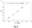
Fig. 5 is a diagram illustrating a result of calculating a relationship between the V value and a coefficient A. -
Fig. 6 is a diagram illustrating a result of calculating a relationship between the V value and a coefficient B. -
Fig. 7 is a diagram illustrating a relationship between the amount of inter-mode coupling and an impulse response. -
Fig. 8 is a diagram illustrating a relationship between the amount of inter-mode coupling and animpulse response 20 dB down width. -
Fig. 9 is a diagram illustrating a core configuration design region satisfying optical characteristics of ITU-T G.652. -
Fig. 10 is a diagram illustrating an example of a core arrangement of the multi-core optical fiber. -
Fig. 11 is Table 1 illustrating a result of calculating an upper limit and lower limit of a core pitch and an upper limit and lower limit of a mode coupling coefficient for acquiring the mode coupling of -30 dB/m or more, with respect to a twisting rate. -
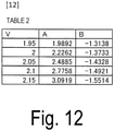
Fig. 12 is Table 2 illustrating a relationship between the V value, the coefficient A, and the coefficient B. -
Fig. 13 is a diagram illustrating a multi-core optical fiber having a trench structure. - Embodiments of the present invention will be described with reference to the accompanying drawings. The embodiments described below are examples of the present invention and the present invention is not limited to the embodiments described below. Note that components with the same reference signs in the specification and the drawings are assumed to be the same components.
-
Fig. 1 is a cross-sectional view of a multi-coreoptical fiber 11 with two cores. There are acore region 12 having a refractive index of n1 and aclad region 13 having a refractive index of n2, where n1 > n2. - In the configuration of
Fig. 1 , the condition of n1 > n2 can be attained by using materials for those regions, such as pure quartz glass, or quartz glass to which impurities that increase the refractive index are added such as germanium (Ge), aluminum (Al), or phosphorus (P) or impurities that decrease the refractive index such as fluorine (F) or boron (B). An inter-core distance is represented by A. - In designing the coupling type multi-core fiber, as for a bend radius, it is reasonable to use the bend radius of 140 mm for calculation to cable the optical fiber and install the cable because it is meant that a bend of the bend radius of 140 mm is effectively generated in the cable as in the definition that an optical fiber strand to which a bend of the bend radius of 140 mm is imparted is used as an alternative instead of using a cable sample in measuring a cut-off wavelength in ITU-T (see
NPLs 7 and 8). - The optical fiber twisting is thought to be generated in producing the optical fiber, and the optical fiber not twisted at all is generally unrealistic. As described in
NPLs - Note that a relationship between a twist pitch P and a twisting rate γ is represented by γ = 2 x π/P (rad/m).
- Here,
Fig. 2 illustrates the core interval A where an inter-mode coupling of (A) -30 dB/m or more, (B) -20 dB/m or more, or (C) -10 dB/m or more occurs, and a coupling coefficient κ calculated from a core configuration for acquiring the inter-mode coupling, when the bend radius is 140mm and the twisting rate is 4πrad/m in the two-core fiber. A wavelength is assumed to be 1550 nm. Hereinafter, a coupling of -30 dB/km is referred to as a random coupling. Note that the horizontal axis represents a relative index difference Δ of the core, assuming a step type core in which a core radius a is adjusted so that the V value is 2.162. - Note that V represents a normalized frequency, and
[Math. 1]
- Although in a core of a general single-mode fiber (core radius is 4.4 µm and relative index difference Δ = 0.35%), the V value is 2.162, and thus, V = 2.162 is used as the V value in a standard single-mode core, another value may be used.
- Here, calculation of the coupling coefficient κ generally uses an equation below:
[Math. 2]
- Note that in a case that the refractive index of the core is a step type, the coupling coefficient is determined by the following:
[Math. 3]
- Here, a description is given to describe that the coupling coefficient in Math. 3 can be also applied to a multi-core optical fiber with N cores. The mode coupling coefficient is defined as a value between two cores, and thus, for a multi-core configuration with N cores (N is an integer of 3 or more) also, a mode coupling coefficient between any two cores can be calculated. Accordingly, the present invention can be applied to any number of cores. However, in the present invention characterized by a desired amount of mode coupling between adjacent cores, it is only required that conditions described below be satisfied between the adjacent cores which are the closest in distance.
- As illustrated in
Fig. 2 , a maximum value and a minimum value of the core pitch for acquiring the random coupling change depending on Δ of the core. On the other hand, the coupling coefficient κ for acquiring the random coupling is in a range from 0.5 to 120 m-1 independently from Δ of the core. - Note that in a case that the mode coupling is -20 dB/m, it is possible and more desirable to further reduce the impulse response width as described later. In this case, as illustrated in
Fig. 2(B) , it is only required that the coupling coefficient κ be in a range from 2.0 to 98 m-1 independently from Δ of the core. - Note that in a case that the mode coupling is -10 dB/m, it is possible and more desirable to further reduce the impulse response width. In this case, as illustrated in
Fig. 2(C) , it is only required that the coupling coefficient κ be in a range from 6.6 to 77.1 m-1 independently from Δ of the core. -
Fig. 3 illustrates the core interval A where an inter-mode coupling of (A) -30 dB/m or more, (B) -20 dB/m or more, or (C) -10 dB/m or more occurs, and a coupling coefficient κ calculated from a core configuration for acquiring the inter-mode coupling with the V value being varied, when the bend radius is 140mm and the twisting rate is 4πrad/m in the two-core fiber. A wavelength is assumed to be 1550 nm. In this calculation, the relative index difference Δ is assumed to be 0.35% and constant. By varying the V value in a range from 2 to 2.3, a normal single-mode fiber core configuration is almost covered. Note that the V value is expressed by equations below, and thus, the V value can be varied by changing parameters included in the equations below.
- As illustrated in
Fig. 3(A) , it is found that the coupling coefficient κ for generating the random coupling is in a range from 0.5 to 130 m-1 independently from the V value. - Note that in a case that the mode coupling is -20 dB/m, it is possible and more desirable to further reduce the impulse response width as described later. In this case, as illustrated in
Fig. 3(B) , it is only required that the coupling coefficient κ be in a range from 2.2 to 100 m-1 independently from the V value. - Note that in a case that the mode coupling is -10 dB/m, it is possible and more desirable to further reduce the impulse response width. In this case, as illustrated in
Fig. 3(C) , it is only required that the coupling coefficient κ be in a range from 7.3 to 79.2 m-1 independently from the V value. - In other words, in consideration of both
Figs. 2 and3 , in order to acquire the random coupling (the inter-mode coupling is -30 dB/m), it is only required that the coupling coefficient κ be in a range from 0.5 to 120 m-1 even if the core has any configuration. - More desirably, in order to acquire a stronger random coupling (the inter-mode coupling is -20 dB/m), it is only required that the coupling coefficient κ be in a range from 2.2 to 98 m-1 even if the core has any configuration.
- More desirably, in order to acquire a stronger random coupling (the inter-mode coupling is -10 dB/m), it is only required that the coupling coefficient κ be in a range from 7.3 to 77.1 m-1 even if the core has any configuration.
- Here, the ranges of the random coupling described above are known to change depending on the twisting rate of the optical fiber.
Fig. 4 illustrates the core interval A where an inter-mode coupling of (A) -30 dB/m or more, (B) -20 dB/m or more, or (C) -10 dB/m or more with respect to the twisting rate occurs, and a coupling coefficient κ calculated from a core configuration for acquiring the inter-mode coupling. Note that the core radius a is assumed to be 4.4µm, and the relative index difference Δ is assumed to be 0.35%. - As can be seen from
Fig. 4 , the range of the core pitch A where the random coupling occurs is constant independently from the twisting rate. The range of the coupling coefficient κ where the random coupling occurs slightly increases as the twisting rate increases. In consideration of a twisting cycle being 4πrad/m or more, it is only required that the coupling coefficient κ for acquiring the random coupling be in a range from 0.73 to 120 m-1. Note that details of data inFig. 4(A) are illustrated in Table 1 inFig. 11 . In consideration of core configuration dependency illustrated inFigs. 2(A) and3(A) or the like, it is only required that the coupling coefficient κ be in a range from 0.73 to 120 m-1. - Note that in a case that the mode coupling is -20 dB/m, it is possible and more desirable to further reduce the impulse response width as described later. In this case, as illustrated in
Fig. 4(B) , it is only required that the coupling coefficient κ be in a range from 2.2 to 100 m-1. In consideration of core configuration dependency illustrated inFigs. 2(B) and3(B) or the like, it is only required that the coupling coefficient κ be in a range from 2.2 to 98 m-1. - Note that in a case that the mode coupling is -10 dB/m, it is possible and more desirable to further reduce the impulse response width. In this case, as illustrated in
Fig. 4(C) , it is only required that the coupling coefficient κ be in a range from 6.6 to 84 m-1. In consideration of core configuration dependency illustrated inFigs. 2(C) and3(C) or the like, it is only required that the coupling coefficient κ be in a range from 7.3 to 77.1 m-1. - According to the above study, by setting the core interval A for generating the coupling coefficient described above, the multi-core optical fiber generating the random coupling independently from the core interval can be designed.
- The first embodiment describes that the core interval required for acquiring the random coupling changes depending on the core configuration such as Δ, but the coupling coefficient κ required for acquiring the random coupling is constant. Here, according to Fig. 4.16 in
NPL 11, a relationship between aκ/√Δ and Λ/a including the coupling coefficient κ can be described using a standardized frequency V as a function, and can be expressed as below using constants A and B.
[Math. 5]
- Here, assuming the step type core, variations in A and B for the V value are calculated and values are empirically found to give Table 2 in
Fig. 12 . Results of deriving the relationship between A and B, and the V value from Table 2 are illustrated inFigs. 5 and6 . FromFigs. 5 and6 ,

- κ required for the random coupling is κc. For example, when the mode coupling of -30 dB/m or more is acquired, 0.73 < κc < 120(m-1) as described in the first embodiment. Here, a range of κc is κ min < κc < κ max. For any step type core configuration by substituting the V value of the core, the core radius a, the relative index difference Δ, and κc into Math. 4, the core interval for acquiring the random coupling can be determined. In other words, it is only required that the core interval Λ satisfy the following.
[Math. 6]
[Math. 6-1]
- Here, what coupling amount gives the random coupling to reduce the impulse response width is calculated. In consideration of a relay zone interposed between optical amplifiers being generally 40 km or more, a result of calculating an impulse response shape when a transmission distance is 40 km and the coupling amount is varied is illustrated in
Fig. 7 . The DMD between the modes is assumed to be 1 ns/km, for convenience. - At -50 dB/m, a pulse indicating a large intensity is present on both ends, and a width of the pulse is 40 ns the same as of an accumulated DMD (1 ns/km x 40 km). In the case of -40 dB/m, although the pulse intensity on both ends decreases, the impulse response width is the same as of the accumulated DMD.
- On the other hand, in the case of the coupling amount of -30 dB/m or more, the impulse response shape is a Gaussian shape. It is well known that in a case that the inter-mode coupling is strong, the impulse response shape is a Gaussian shape. In the case of -20 dB/km, it can be seen that the Gaussian shape is similarly obtained, but a width thereof is further smaller.
-
Fig. 8 illustrates the amount of inter-mode coupling and animpulse response 20 dB down width that are calculated. As described in the above calculation, the advantageous reduction effect of the impulse response width is observed over the coupling amount of -30 dB/m or more. - According to
NPL 12, if the impulse response shape is a Gaussian shape, the impulse response width thereof is proportional to a square root of the distance, which is advantageous in that the impulse response width can be reduced particularly in a long distance transmission as compared to an uncoupled fiber that is proportional to the distance. - As described above, it can be thought that the random coupling occurs in the region of - 30 dB/m or more where a significant reduction effect of the impulse response width is obtained.
- In a case of, for each core of the multi-core optical fiber, satisfying the optical characteristics of G.652 that is the general single-mode fiber standard recommended in ITU-T, for example, a cut-off wavelength should be 1.26 µm or less, a bending loss should be 0.1 dB/100 turn or less at a wavelength of 1625 nm and a bend radius of 30 mm, and a mode field diameter should be 8.2 to 9.6 µm at a wavelength of 1310 nm.
-
Fig. 9 is a diagram illustrating core configuration conditions for each core of the multi-core optical fiber to comply with G.652 (the horizontal axis represents a core radius and the vertical axis represents a relative index difference of the core). A region of the cut-off wavelength of 1.26 µm or less is below a curve A. A region of the bending loss of 0.1 dB/100 turn or less is above a curve B. A region of the mode field diameter of 8.2 to 9.6 µm is between a curve C and a curve D. Specifically, if the core configuration of the multi-core optical fiber corresponds to a hatched region, the multi-core optical fiber satisfies the characteristics of G.652 and a coupling type MCF core capable of using wavelength bands from the O-band to the L-band can be attained. - By designing the multi-core optical fiber that has the core configuration corresponding to the hatched region in
Fig. 9 and has the core interval satisfying the conditions described in the first and second embodiments, the coupling type multi-core optical fiber can be obtained that is for transmission using the desired wavelength band and has the optical characteristics complying with the international standard. In other words, the present invention can provide the coupling type multi-core optical fiber and the design method thereof, the coupling type multi-core optical fiber having the optical characteristics complying with the international standard in the desired wavelength band that has not been clear. - Conceivable examples of a core arrangement of the multi-core optical fiber include a square lattice manner, a hexagonal close-packed structure, an annular manner, and the like with 2 to 19 cores, for example, as illustrated in
Fig. 10 . In this case, the number of lengths between adjacent cores is plural, and the shortest length of the lengths is used as Λ. - The present invention can achieve also a multi-core optical fiber having a trench structure in which a low refractive index clad 14 is present to surround
step type cores 12 as illustrated inFig. 13 . In a case of the multi-core optical fiber having the trench structure, when a relative index difference of the core with respect to a clad 13 is Δ+ and a relative index difference of the low refractive index clad 14 with respect to the clad 13 is Δ-, the low refractive index clad 14 is treated as an effective clad for each of thecores 12. Therefore, it is only required that Δ described above be replaced with
- The multi-core optical fiber according to the present invention can be used as a transmission medium in an optical transmission system. For example, an optical cable for the optical transmission system includes the multi-core optical fiber described in the above embodiments and a sheath covering the multi-core optical fiber with the twist pitch of 500 mm or less.
-
- 11:
- Multi-core optical fiber
- 12:
- Core
- 13:
- Clad
- 14:
- Low refractive region

[Math. C3]

Claims (7)
- A multi-core optical fiber, comprisingtwo or more cores,wherein each of the cores has one propagation mode in a wavelength λ of a desired communication wavelength band, andan inter-mode coupling coefficient κ between adjacent cores which is a minimum interval among the cores is κ min or more and κ max or less,where κ min = 0.73 m-1 and κ max = 120 m-1.
- The multi-core optical fiber according to claim 1,
wherein κ min = 2.2 m-1 and κ max = 98 m-1. - The multi-core optical fiber according to claim 1,
wherein κ min = 7.3 m-1 and κ max = 77.1 m-1. - The multi-core optical fiber according to any one of claims 1 to 3,
wherein a minimum core interval Λ that is an interval between the adjacent cores is in a range satisfying Math. C1,
[Math. C1]
- The multi-core optical fiber according to any one of claims 1 to 4,
wherein a cut-off wavelength is 1.26 µm or less, a bending loss is 0.1 dB/100 turn or less at a wavelength of 1625 nm and a bend radius of 30 mm, and a mode field diameter is 8.2 µm or more and 9.6 µm or less at a wavelength of 1310 nm. - A design method of a multi-core optical fiber, the multi-core optical fiber including two or more cores with a step type refractive index distribution, the design method comprising:with a bend radius of 140 mm and a twisting rate of 4πrad/m, calculating, from a core configuration in which a desired inter-mode coupling occurs between adjacent cores which a core interval is minimum at an arbitrary wavelength λ, an inter-mode coupling coefficient κ between the adjacent cores by using Math. C3 while varying a relative index difference Δ of the cores and keeping a normalized frequency V in Math. C2 a constant value at the arbitrary wavelength λ, to acquire a first inter-mode coupling coefficient range;with a bend radius of 140 mm and a twisting rate of 4 πrad/m, calculating, from a core configuration in which a desired inter-mode coupling occurs at the arbitrary wavelength λ, the inter-mode coupling coefficient κ between the adjacent cores by using Math. C3 while keeping the relative index difference Δ of the cores a constant value and varying a normalized frequency V at the arbitrary wavelength λ, to acquire a second inter-mode coupling coefficient range;with a bend radius of 140 mm, calculating, from a core configuration in which a desired inter-mode coupling occurs at the arbitrary wavelength λ, the inter-mode coupling coefficient κ between the adjacent cores by using Math. C3 while keeping a radius a of the cores and the relative index difference Δ constant values and varying a twisting rate, to acquire a third inter-mode coupling coefficient range; anddetermining inter-mode coupling coefficients κ c of the multi-core optical fiber within a range included in all of the first inter-mode coupling coefficient range, the second inter-mode coupling coefficient range, and the third inter-mode coupling coefficient range,
[Math. C2] where n1 represents a refractive index of the cores,
[Math. C3] where a represents a radius a of the cores, Δ represents a relative index difference, u represents a normalized lateral propagation constant, w represents a normalized lateral attenuation constant, Λ represents the core interval, V represents a normalized frequency, and K1 2(W) represents a modified Bessel function of a second kind.
 - The design method according to claim 6,
wherein a minimum core interval A that is the interval between the adjacent cores is calculated using Math. C1,
[Math. C1]
Applications Claiming Priority (2)
| Application Number | Priority Date | Filing Date | Title |
|---|---|---|---|
| JP2019084500A JP6715372B1 (en) | 2019-04-25 | 2019-04-25 | Multi-core optical fiber and design method |
| PCT/JP2020/015442 WO2020217939A1 (en) | 2019-04-25 | 2020-04-06 | Multicore optical fiber and design method |
Publications (3)
| Publication Number | Publication Date |
|---|---|
| EP3961274A1 true EP3961274A1 (en) | 2022-03-02 |
| EP3961274A4 EP3961274A4 (en) | 2023-01-11 |
| EP3961274B1 EP3961274B1 (en) | 2024-08-07 |
Family
ID=71131646
Family Applications (1)
| Application Number | Title | Priority Date | Filing Date |
|---|---|---|---|
| EP20794731.8A Active EP3961274B1 (en) | 2019-04-25 | 2020-04-06 | Multicore optical fiber |
Country Status (5)
| Country | Link |
|---|---|
| US (1) | US12181706B2 (en) |
| EP (1) | EP3961274B1 (en) |
| JP (1) | JP6715372B1 (en) |
| CN (1) | CN113711094B (en) |
| WO (1) | WO2020217939A1 (en) |
Families Citing this family (16)
| Publication number | Priority date | Publication date | Assignee | Title |
|---|---|---|---|---|
| EP4209810A4 (en) * | 2020-09-04 | 2024-07-24 | Nippon Telegraph And Telephone Corporation | MULTICORE OPTICAL FIBER |
| WO2022065435A1 (en) * | 2020-09-24 | 2022-03-31 | 住友電気工業株式会社 | Multicore optical fiber and optical transmission system |
| JP7720583B2 (en) * | 2021-08-25 | 2025-08-08 | Ntt株式会社 | Multicore Fiber |
| JP7731101B2 (en) * | 2021-09-02 | 2025-08-29 | Ntt株式会社 | Multi-core optical fiber and optical transmission system |
| EP4451028A4 (en) * | 2021-12-17 | 2025-03-26 | Sumitomo Electric Industries, Ltd. | FIBER OPTIC CABLE |
| US12032200B2 (en) * | 2021-12-28 | 2024-07-09 | Sterlite Technologies Limited | Trench assisted multi-core optical fiber with reduced crosstalk |
| EP4502682A4 (en) * | 2022-03-24 | 2025-06-25 | Sumitomo Electric Industries, Ltd. | Multicore optical fiber |
| EP4502683A4 (en) * | 2022-03-30 | 2025-07-09 | Sumitomo Electric Industries | MULTI-CORE FIBER OPTICS |
| WO2024013876A1 (en) * | 2022-07-13 | 2024-01-18 | 日本電信電話株式会社 | Multi-core optical fiber, and design method |
| CN115327697B (en) * | 2022-08-17 | 2024-04-26 | 长飞光纤光缆股份有限公司 | Random coupling multi-core optical fiber, manufacturing method thereof and multi-core optical cable |
| CN115455355B (en) * | 2022-09-16 | 2023-07-25 | 苏州大学 | Method and device for detecting crosstalk between modes of multi-core few-mode optical fibers |
| JP7505664B1 (en) * | 2023-01-31 | 2024-06-25 | 住友電気工業株式会社 | Multi-core optical fiber |
| WO2024161793A1 (en) * | 2023-01-31 | 2024-08-08 | 住友電気工業株式会社 | Multicore optical fiber |
| JP2024118138A (en) * | 2023-02-20 | 2024-08-30 | 日本電信電話株式会社 | Few-mode multi-core optical fiber and optical transmission system |
| WO2025173071A1 (en) * | 2024-02-13 | 2025-08-21 | Ntt株式会社 | Coupling type multicore optical fiber |
| CN117955564B (en) * | 2024-02-22 | 2025-06-27 | 苏州大学 | Method, system and device for detecting crosstalk between modes of weak-coupling few-mode multi-core optical fibers |
Family Cites Families (12)
| Publication number | Priority date | Publication date | Assignee | Title |
|---|---|---|---|---|
| JP5168702B2 (en) * | 2008-10-03 | 2013-03-27 | 国立大学法人横浜国立大学 | Multi-core fiber core placement method |
| JP5708015B2 (en) * | 2010-02-26 | 2015-04-30 | 住友電気工業株式会社 | Fiber optic cable |
| US9103961B2 (en) * | 2011-08-12 | 2015-08-11 | University Of Central Florida Research Foundation, Inc. | Systems and methods for optical transmission using supermodes |
| JP5522696B2 (en) * | 2011-10-13 | 2014-06-18 | 日本電信電話株式会社 | 4-core single-mode optical fiber and optical cable |
| CN105026965A (en) * | 2013-01-10 | 2015-11-04 | 住友电气工业株式会社 | Optical components and optical communication systems |
| JP6532748B2 (en) * | 2015-04-30 | 2019-06-19 | 株式会社フジクラ | Multicore fiber |
| WO2017061184A1 (en) * | 2015-10-08 | 2017-04-13 | 住友電気工業株式会社 | Multicore optical fiber, multicore optical fiber cable, and optical fiber transmission system |
| JP2017072818A (en) * | 2015-10-08 | 2017-04-13 | 住友電気工業株式会社 | Multi-core optical fiber, multi-core optical fiber cable and optical fiber transmission system |
| JP6954294B2 (en) * | 2016-09-09 | 2021-10-27 | 住友電気工業株式会社 | Optical amplifier and multi-core optical fiber |
| JP7268677B2 (en) * | 2018-04-09 | 2023-05-08 | 住友電気工業株式会社 | Multi-core optical fiber and multi-core optical fiber cable |
| CN109283613A (en) * | 2018-11-26 | 2019-01-29 | 北京交通大学 | A low inter-core crosstalk multi-core fiber |
| JP7326933B2 (en) * | 2019-07-03 | 2023-08-16 | 住友電気工業株式会社 | multicore optical fiber |
-
2019
- 2019-04-25 JP JP2019084500A patent/JP6715372B1/en active Active
-
2020
- 2020-04-06 EP EP20794731.8A patent/EP3961274B1/en active Active
- 2020-04-06 WO PCT/JP2020/015442 patent/WO2020217939A1/en not_active Ceased
- 2020-04-06 CN CN202080029841.9A patent/CN113711094B/en active Active
- 2020-04-06 US US17/605,758 patent/US12181706B2/en active Active
Also Published As
| Publication number | Publication date |
|---|---|
| WO2020217939A1 (en) | 2020-10-29 |
| CN113711094B (en) | 2023-06-30 |
| JP2020181106A (en) | 2020-11-05 |
| US12181706B2 (en) | 2024-12-31 |
| EP3961274A4 (en) | 2023-01-11 |
| CN113711094A (en) | 2021-11-26 |
| EP3961274B1 (en) | 2024-08-07 |
| JP6715372B1 (en) | 2020-07-01 |
| US20220214496A1 (en) | 2022-07-07 |
Similar Documents
| Publication | Publication Date | Title |
|---|---|---|
| EP3961274B1 (en) | Multicore optical fiber | |
| EP2706387B1 (en) | Multiple LP-mode fiber designs for mode-division multiplexing | |
| US8094985B2 (en) | Multi-core holey fiber and optical transmission system | |
| JP3320745B2 (en) | Dispersion flat optical fiber | |
| EP1498753B1 (en) | Graded-index multimode fiber and manufacturing method therefor | |
| US9020316B2 (en) | Low attenuation optical fibers with an F-graded index core | |
| JP4065716B2 (en) | Positive dispersion optical fiber with wide effective area | |
| JP6397898B2 (en) | Low-mode optical fiber for space division multiplexing. | |
| JP5193398B2 (en) | Optical fiber and optical transmission system | |
| JP6361101B2 (en) | Optical fiber | |
| US5732178A (en) | Single-mode optical fiber | |
| JP6453166B2 (en) | Multi-core optical fiber, optical fiber manufacturing method, and optical fiber cable manufacturing method | |
| EP2657732B1 (en) | Multi-core fiber | |
| US8315494B2 (en) | Optical fiber | |
| JP2017167196A (en) | Multi-core optical fiber and multi-core optical fiber design method | |
| WO2010119930A1 (en) | Multi-core optical fiber | |
| JP7364192B2 (en) | Multi-core optical fiber and fiber optic cable | |
| JP7320788B2 (en) | Coupled multi-core optical fiber | |
| EP1507154B1 (en) | Dispersion shift optical fiber | |
| Seraji et al. | A revisit of refractive index profiles design for reduction of positive dispersion, splice loss, and enhancement of negative dispersion in optical transmission lines | |
| Sagae et al. | Solid-type low-latency optical fiber with large effective area | |
| US20030044148A1 (en) | Controlled dispersion optical fiber | |
| US12189178B2 (en) | Optical fiber | |
| EP3492956A1 (en) | Non-zero dispersion shifted fiber with low cut off wavelength and large effective area |
Legal Events
| Date | Code | Title | Description |
|---|---|---|---|
| STAA | Information on the status of an ep patent application or granted ep patent |
Free format text: STATUS: THE INTERNATIONAL PUBLICATION HAS BEEN MADE |
|
| PUAI | Public reference made under article 153(3) epc to a published international application that has entered the european phase |
Free format text: ORIGINAL CODE: 0009012 |
|
| STAA | Information on the status of an ep patent application or granted ep patent |
Free format text: STATUS: REQUEST FOR EXAMINATION WAS MADE |
|
| 17P | Request for examination filed |
Effective date: 20211125 |
|
| AK | Designated contracting states |
Kind code of ref document: A1 Designated state(s): AL AT BE BG CH CY CZ DE DK EE ES FI FR GB GR HR HU IE IS IT LI LT LU LV MC MK MT NL NO PL PT RO RS SE SI SK SM TR |
|
| DAV | Request for validation of the european patent (deleted) | ||
| DAX | Request for extension of the european patent (deleted) | ||
| A4 | Supplementary search report drawn up and despatched |
Effective date: 20221208 |
|
| RIC1 | Information provided on ipc code assigned before grant |
Ipc: G02B 6/02 20060101AFI20221202BHEP |
|
| STAA | Information on the status of an ep patent application or granted ep patent |
Free format text: STATUS: EXAMINATION IS IN PROGRESS |
|
| 17Q | First examination report despatched |
Effective date: 20230825 |
|
| GRAP | Despatch of communication of intention to grant a patent |
Free format text: ORIGINAL CODE: EPIDOSNIGR1 |
|
| STAA | Information on the status of an ep patent application or granted ep patent |
Free format text: STATUS: GRANT OF PATENT IS INTENDED |
|
| INTG | Intention to grant announced |
Effective date: 20240301 |
|
| GRAS | Grant fee paid |
Free format text: ORIGINAL CODE: EPIDOSNIGR3 |
|
| GRAA | (expected) grant |
Free format text: ORIGINAL CODE: 0009210 |
|
| STAA | Information on the status of an ep patent application or granted ep patent |
Free format text: STATUS: THE PATENT HAS BEEN GRANTED |
|
| AK | Designated contracting states |
Kind code of ref document: B1 Designated state(s): AL AT BE BG CH CY CZ DE DK EE ES FI FR GB GR HR HU IE IS IT LI LT LU LV MC MK MT NL NO PL PT RO RS SE SI SK SM TR |
|
| REG | Reference to a national code |
Ref country code: GB Ref legal event code: FG4D |
|
| REG | Reference to a national code |
Ref country code: CH Ref legal event code: EP |
|
| REG | Reference to a national code |
Ref country code: IE Ref legal event code: FG4D |
|
| REG | Reference to a national code |
Ref country code: DE Ref legal event code: R096 Ref document number: 602020035429 Country of ref document: DE |
|
| REG | Reference to a national code |
Ref country code: LT Ref legal event code: MG9D |
|
| REG | Reference to a national code |
Ref country code: NL Ref legal event code: MP Effective date: 20240807 |
|
| PG25 | Lapsed in a contracting state [announced via postgrant information from national office to epo] |
Ref country code: NO Free format text: LAPSE BECAUSE OF FAILURE TO SUBMIT A TRANSLATION OF THE DESCRIPTION OR TO PAY THE FEE WITHIN THE PRESCRIBED TIME-LIMIT Effective date: 20241107 |
|
| REG | Reference to a national code |
Ref country code: AT Ref legal event code: MK05 Ref document number: 1711571 Country of ref document: AT Kind code of ref document: T Effective date: 20240807 |
|
| PG25 | Lapsed in a contracting state [announced via postgrant information from national office to epo] |
Ref country code: NL Free format text: LAPSE BECAUSE OF FAILURE TO SUBMIT A TRANSLATION OF THE DESCRIPTION OR TO PAY THE FEE WITHIN THE PRESCRIBED TIME-LIMIT Effective date: 20240807 Ref country code: FI Free format text: LAPSE BECAUSE OF FAILURE TO SUBMIT A TRANSLATION OF THE DESCRIPTION OR TO PAY THE FEE WITHIN THE PRESCRIBED TIME-LIMIT Effective date: 20240807 Ref country code: PL Free format text: LAPSE BECAUSE OF FAILURE TO SUBMIT A TRANSLATION OF THE DESCRIPTION OR TO PAY THE FEE WITHIN THE PRESCRIBED TIME-LIMIT Effective date: 20240807 Ref country code: GR Free format text: LAPSE BECAUSE OF FAILURE TO SUBMIT A TRANSLATION OF THE DESCRIPTION OR TO PAY THE FEE WITHIN THE PRESCRIBED TIME-LIMIT Effective date: 20241108 Ref country code: PT Free format text: LAPSE BECAUSE OF FAILURE TO SUBMIT A TRANSLATION OF THE DESCRIPTION OR TO PAY THE FEE WITHIN THE PRESCRIBED TIME-LIMIT Effective date: 20241209 |
|
| PG25 | Lapsed in a contracting state [announced via postgrant information from national office to epo] |
Ref country code: BG Free format text: LAPSE BECAUSE OF FAILURE TO SUBMIT A TRANSLATION OF THE DESCRIPTION OR TO PAY THE FEE WITHIN THE PRESCRIBED TIME-LIMIT Effective date: 20240807 |
|
| PG25 | Lapsed in a contracting state [announced via postgrant information from national office to epo] |
Ref country code: LV Free format text: LAPSE BECAUSE OF FAILURE TO SUBMIT A TRANSLATION OF THE DESCRIPTION OR TO PAY THE FEE WITHIN THE PRESCRIBED TIME-LIMIT Effective date: 20240807 |
|
| PG25 | Lapsed in a contracting state [announced via postgrant information from national office to epo] |
Ref country code: AT Free format text: LAPSE BECAUSE OF FAILURE TO SUBMIT A TRANSLATION OF THE DESCRIPTION OR TO PAY THE FEE WITHIN THE PRESCRIBED TIME-LIMIT Effective date: 20240807 Ref country code: IS Free format text: LAPSE BECAUSE OF FAILURE TO SUBMIT A TRANSLATION OF THE DESCRIPTION OR TO PAY THE FEE WITHIN THE PRESCRIBED TIME-LIMIT Effective date: 20241207 |
|
| PG25 | Lapsed in a contracting state [announced via postgrant information from national office to epo] |
Ref country code: HR Free format text: LAPSE BECAUSE OF FAILURE TO SUBMIT A TRANSLATION OF THE DESCRIPTION OR TO PAY THE FEE WITHIN THE PRESCRIBED TIME-LIMIT Effective date: 20240807 |
|
| PG25 | Lapsed in a contracting state [announced via postgrant information from national office to epo] |
Ref country code: RS Free format text: LAPSE BECAUSE OF FAILURE TO SUBMIT A TRANSLATION OF THE DESCRIPTION OR TO PAY THE FEE WITHIN THE PRESCRIBED TIME-LIMIT Effective date: 20241107 Ref country code: ES Free format text: LAPSE BECAUSE OF FAILURE TO SUBMIT A TRANSLATION OF THE DESCRIPTION OR TO PAY THE FEE WITHIN THE PRESCRIBED TIME-LIMIT Effective date: 20240807 |
|
| PG25 | Lapsed in a contracting state [announced via postgrant information from national office to epo] |
Ref country code: RS Free format text: LAPSE BECAUSE OF FAILURE TO SUBMIT A TRANSLATION OF THE DESCRIPTION OR TO PAY THE FEE WITHIN THE PRESCRIBED TIME-LIMIT Effective date: 20241107 Ref country code: PT Free format text: LAPSE BECAUSE OF FAILURE TO SUBMIT A TRANSLATION OF THE DESCRIPTION OR TO PAY THE FEE WITHIN THE PRESCRIBED TIME-LIMIT Effective date: 20241209 Ref country code: PL Free format text: LAPSE BECAUSE OF FAILURE TO SUBMIT A TRANSLATION OF THE DESCRIPTION OR TO PAY THE FEE WITHIN THE PRESCRIBED TIME-LIMIT Effective date: 20240807 Ref country code: NO Free format text: LAPSE BECAUSE OF FAILURE TO SUBMIT A TRANSLATION OF THE DESCRIPTION OR TO PAY THE FEE WITHIN THE PRESCRIBED TIME-LIMIT Effective date: 20241107 Ref country code: NL Free format text: LAPSE BECAUSE OF FAILURE TO SUBMIT A TRANSLATION OF THE DESCRIPTION OR TO PAY THE FEE WITHIN THE PRESCRIBED TIME-LIMIT Effective date: 20240807 Ref country code: LV Free format text: LAPSE BECAUSE OF FAILURE TO SUBMIT A TRANSLATION OF THE DESCRIPTION OR TO PAY THE FEE WITHIN THE PRESCRIBED TIME-LIMIT Effective date: 20240807 Ref country code: IS Free format text: LAPSE BECAUSE OF FAILURE TO SUBMIT A TRANSLATION OF THE DESCRIPTION OR TO PAY THE FEE WITHIN THE PRESCRIBED TIME-LIMIT Effective date: 20241207 Ref country code: HR Free format text: LAPSE BECAUSE OF FAILURE TO SUBMIT A TRANSLATION OF THE DESCRIPTION OR TO PAY THE FEE WITHIN THE PRESCRIBED TIME-LIMIT Effective date: 20240807 Ref country code: GR Free format text: LAPSE BECAUSE OF FAILURE TO SUBMIT A TRANSLATION OF THE DESCRIPTION OR TO PAY THE FEE WITHIN THE PRESCRIBED TIME-LIMIT Effective date: 20241108 Ref country code: FI Free format text: LAPSE BECAUSE OF FAILURE TO SUBMIT A TRANSLATION OF THE DESCRIPTION OR TO PAY THE FEE WITHIN THE PRESCRIBED TIME-LIMIT Effective date: 20240807 Ref country code: ES Free format text: LAPSE BECAUSE OF FAILURE TO SUBMIT A TRANSLATION OF THE DESCRIPTION OR TO PAY THE FEE WITHIN THE PRESCRIBED TIME-LIMIT Effective date: 20240807 Ref country code: BG Free format text: LAPSE BECAUSE OF FAILURE TO SUBMIT A TRANSLATION OF THE DESCRIPTION OR TO PAY THE FEE WITHIN THE PRESCRIBED TIME-LIMIT Effective date: 20240807 Ref country code: AT Free format text: LAPSE BECAUSE OF FAILURE TO SUBMIT A TRANSLATION OF THE DESCRIPTION OR TO PAY THE FEE WITHIN THE PRESCRIBED TIME-LIMIT Effective date: 20240807 |
|
| PG25 | Lapsed in a contracting state [announced via postgrant information from national office to epo] |
Ref country code: DK Free format text: LAPSE BECAUSE OF FAILURE TO SUBMIT A TRANSLATION OF THE DESCRIPTION OR TO PAY THE FEE WITHIN THE PRESCRIBED TIME-LIMIT Effective date: 20240807 Ref country code: SM Free format text: LAPSE BECAUSE OF FAILURE TO SUBMIT A TRANSLATION OF THE DESCRIPTION OR TO PAY THE FEE WITHIN THE PRESCRIBED TIME-LIMIT Effective date: 20240807 |
|
| PG25 | Lapsed in a contracting state [announced via postgrant information from national office to epo] |
Ref country code: EE Free format text: LAPSE BECAUSE OF FAILURE TO SUBMIT A TRANSLATION OF THE DESCRIPTION OR TO PAY THE FEE WITHIN THE PRESCRIBED TIME-LIMIT Effective date: 20240807 |
|
| PG25 | Lapsed in a contracting state [announced via postgrant information from national office to epo] |
Ref country code: CZ Free format text: LAPSE BECAUSE OF FAILURE TO SUBMIT A TRANSLATION OF THE DESCRIPTION OR TO PAY THE FEE WITHIN THE PRESCRIBED TIME-LIMIT Effective date: 20240807 |
|
| PG25 | Lapsed in a contracting state [announced via postgrant information from national office to epo] |
Ref country code: SK Free format text: LAPSE BECAUSE OF FAILURE TO SUBMIT A TRANSLATION OF THE DESCRIPTION OR TO PAY THE FEE WITHIN THE PRESCRIBED TIME-LIMIT Effective date: 20240807 |
|
| REG | Reference to a national code |
Ref country code: DE Ref legal event code: R097 Ref document number: 602020035429 Country of ref document: DE |
|
| PLBE | No opposition filed within time limit |
Free format text: ORIGINAL CODE: 0009261 |
|
| STAA | Information on the status of an ep patent application or granted ep patent |
Free format text: STATUS: NO OPPOSITION FILED WITHIN TIME LIMIT |
|
| 26N | No opposition filed |
Effective date: 20250508 |
|
| PGFP | Annual fee paid to national office [announced via postgrant information from national office to epo] |
Ref country code: FR Payment date: 20250425 Year of fee payment: 6 |
|
| PG25 | Lapsed in a contracting state [announced via postgrant information from national office to epo] |
Ref country code: SE Free format text: LAPSE BECAUSE OF FAILURE TO SUBMIT A TRANSLATION OF THE DESCRIPTION OR TO PAY THE FEE WITHIN THE PRESCRIBED TIME-LIMIT Effective date: 20240807 |
|
| REG | Reference to a national code |
Ref country code: DE Ref legal event code: R119 Ref document number: 602020035429 Country of ref document: DE |
|
| REG | Reference to a national code |
Ref country code: CH Ref legal event code: H13 Free format text: ST27 STATUS EVENT CODE: U-0-0-H10-H13 (AS PROVIDED BY THE NATIONAL OFFICE) Effective date: 20251125 |
|
| PG25 | Lapsed in a contracting state [announced via postgrant information from national office to epo] |
Ref country code: LU Free format text: LAPSE BECAUSE OF NON-PAYMENT OF DUE FEES Effective date: 20250406 |
|
| PG25 | Lapsed in a contracting state [announced via postgrant information from national office to epo] |
Ref country code: MC Free format text: LAPSE BECAUSE OF FAILURE TO SUBMIT A TRANSLATION OF THE DESCRIPTION OR TO PAY THE FEE WITHIN THE PRESCRIBED TIME-LIMIT Effective date: 20240807 |
|
| GBPC | Gb: european patent ceased through non-payment of renewal fee |
Effective date: 20250406 |
|
| REG | Reference to a national code |
Ref country code: BE Ref legal event code: MM Effective date: 20250430 |
|
| PG25 | Lapsed in a contracting state [announced via postgrant information from national office to epo] |
Ref country code: DE Free format text: LAPSE BECAUSE OF NON-PAYMENT OF DUE FEES Effective date: 20251104 |
|
| PG25 | Lapsed in a contracting state [announced via postgrant information from national office to epo] |
Ref country code: GB Free format text: LAPSE BECAUSE OF NON-PAYMENT OF DUE FEES Effective date: 20250406 |
|
| PG25 | Lapsed in a contracting state [announced via postgrant information from national office to epo] |
Ref country code: BE Free format text: LAPSE BECAUSE OF NON-PAYMENT OF DUE FEES Effective date: 20250430 |
|
| PG25 | Lapsed in a contracting state [announced via postgrant information from national office to epo] |
Ref country code: CH Free format text: LAPSE BECAUSE OF NON-PAYMENT OF DUE FEES Effective date: 20250430 |
|
| PG25 | Lapsed in a contracting state [announced via postgrant information from national office to epo] |
Ref country code: IT Free format text: LAPSE BECAUSE OF FAILURE TO SUBMIT A TRANSLATION OF THE DESCRIPTION OR TO PAY THE FEE WITHIN THE PRESCRIBED TIME-LIMIT Effective date: 20240807 |
|
| PG25 | Lapsed in a contracting state [announced via postgrant information from national office to epo] |
Ref country code: IE Free format text: LAPSE BECAUSE OF NON-PAYMENT OF DUE FEES Effective date: 20250406 |
|
| PG25 | Lapsed in a contracting state [announced via postgrant information from national office to epo] |
Ref country code: RO Free format text: LAPSE BECAUSE OF FAILURE TO SUBMIT A TRANSLATION OF THE DESCRIPTION OR TO PAY THE FEE WITHIN THE PRESCRIBED TIME-LIMIT Effective date: 20240807 |