EP3961234A1 - Apparatus and method for diagnosing abnormal degradation of battery cell - Google Patents
Apparatus and method for diagnosing abnormal degradation of battery cell Download PDFInfo
- Publication number
- EP3961234A1 EP3961234A1 EP20892272.4A EP20892272A EP3961234A1 EP 3961234 A1 EP3961234 A1 EP 3961234A1 EP 20892272 A EP20892272 A EP 20892272A EP 3961234 A1 EP3961234 A1 EP 3961234A1
- Authority
- EP
- European Patent Office
- Prior art keywords
- soc
- change amount
- battery cells
- battery
- battery cell
- Prior art date
- Legal status (The legal status is an assumption and is not a legal conclusion. Google has not performed a legal analysis and makes no representation as to the accuracy of the status listed.)
- Granted
Links
Images


Classifications
-
- G—PHYSICS
- G01—MEASURING; TESTING
- G01R—MEASURING ELECTRIC VARIABLES; MEASURING MAGNETIC VARIABLES
- G01R31/00—Arrangements for testing electric properties; Arrangements for locating electric faults; Arrangements for electrical testing characterised by what is being tested not provided for elsewhere
- G01R31/36—Arrangements for testing, measuring or monitoring the electrical condition of accumulators or electric batteries, e.g. capacity or state of charge [SoC]
- G01R31/385—Arrangements for measuring battery or accumulator variables
- G01R31/387—Determining ampere-hour charge capacity or SoC
- G01R31/388—Determining ampere-hour charge capacity or SoC involving voltage measurements
-
- G—PHYSICS
- G01—MEASURING; TESTING
- G01R—MEASURING ELECTRIC VARIABLES; MEASURING MAGNETIC VARIABLES
- G01R31/00—Arrangements for testing electric properties; Arrangements for locating electric faults; Arrangements for electrical testing characterised by what is being tested not provided for elsewhere
- G01R31/36—Arrangements for testing, measuring or monitoring the electrical condition of accumulators or electric batteries, e.g. capacity or state of charge [SoC]
- G01R31/392—Determining battery ageing or deterioration, e.g. state of health
-
- G—PHYSICS
- G01—MEASURING; TESTING
- G01R—MEASURING ELECTRIC VARIABLES; MEASURING MAGNETIC VARIABLES
- G01R31/00—Arrangements for testing electric properties; Arrangements for locating electric faults; Arrangements for electrical testing characterised by what is being tested not provided for elsewhere
- G01R31/36—Arrangements for testing, measuring or monitoring the electrical condition of accumulators or electric batteries, e.g. capacity or state of charge [SoC]
- G01R31/382—Arrangements for monitoring battery or accumulator variables, e.g. SoC
- G01R31/3842—Arrangements for monitoring battery or accumulator variables, e.g. SoC combining voltage and current measurements
-
- G—PHYSICS
- G01—MEASURING; TESTING
- G01R—MEASURING ELECTRIC VARIABLES; MEASURING MAGNETIC VARIABLES
- G01R31/00—Arrangements for testing electric properties; Arrangements for locating electric faults; Arrangements for electrical testing characterised by what is being tested not provided for elsewhere
- G01R31/36—Arrangements for testing, measuring or monitoring the electrical condition of accumulators or electric batteries, e.g. capacity or state of charge [SoC]
- G01R31/396—Acquisition or processing of data for testing or for monitoring individual cells or groups of cells within a battery
-
- G—PHYSICS
- G01—MEASURING; TESTING
- G01R—MEASURING ELECTRIC VARIABLES; MEASURING MAGNETIC VARIABLES
- G01R31/00—Arrangements for testing electric properties; Arrangements for locating electric faults; Arrangements for electrical testing characterised by what is being tested not provided for elsewhere
- G01R31/36—Arrangements for testing, measuring or monitoring the electrical condition of accumulators or electric batteries, e.g. capacity or state of charge [SoC]
- G01R31/385—Arrangements for measuring battery or accumulator variables
- G01R31/387—Determining ampere-hour charge capacity or SoC
-
- H—ELECTRICITY
- H02—GENERATION; CONVERSION OR DISTRIBUTION OF ELECTRIC POWER
- H02J—ELECTRIC POWER NETWORKS; CIRCUIT ARRANGEMENTS OR SYSTEMS FOR SUPPLYING OR DISTRIBUTING ELECTRIC POWER; SYSTEMS FOR STORING ELECTRIC ENERGY
- H02J7/00—Circuit arrangements for charging or discharging batteries or for supplying loads from batteries
- H02J7/80—Circuit arrangements for charging or discharging batteries or for supplying loads from batteries including monitoring or indicating arrangements
- H02J7/82—Control of state of charge [SOC]
-
- H—ELECTRICITY
- H02—GENERATION; CONVERSION OR DISTRIBUTION OF ELECTRIC POWER
- H02J—ELECTRIC POWER NETWORKS; CIRCUIT ARRANGEMENTS OR SYSTEMS FOR SUPPLYING OR DISTRIBUTING ELECTRIC POWER; SYSTEMS FOR STORING ELECTRIC ENERGY
- H02J7/00—Circuit arrangements for charging or discharging batteries or for supplying loads from batteries
- H02J7/80—Circuit arrangements for charging or discharging batteries or for supplying loads from batteries including monitoring or indicating arrangements
- H02J7/84—Control of state of health [SOH]
-
- Y—GENERAL TAGGING OF NEW TECHNOLOGICAL DEVELOPMENTS; GENERAL TAGGING OF CROSS-SECTIONAL TECHNOLOGIES SPANNING OVER SEVERAL SECTIONS OF THE IPC; TECHNICAL SUBJECTS COVERED BY FORMER USPC CROSS-REFERENCE ART COLLECTIONS [XRACs] AND DIGESTS
- Y02—TECHNOLOGIES OR APPLICATIONS FOR MITIGATION OR ADAPTATION AGAINST CLIMATE CHANGE
- Y02E—REDUCTION OF GREENHOUSE GAS [GHG] EMISSIONS, RELATED TO ENERGY GENERATION, TRANSMISSION OR DISTRIBUTION
- Y02E60/00—Enabling technologies; Technologies with a potential or indirect contribution to GHG emissions mitigation
- Y02E60/10—Energy storage using batteries
Definitions
- the present invention claims the benefit of priority based on Korean Patent Application No. 10-2019-0156065 filed on November 28, 2019 , and includes all contents disclosed in the documents of the Korean patent application as part of this specification.
- the present invention relates to an apparatus and method for diagnosing abnormal deterioration of battery cells.
- the secondary battery is provided in the form of a battery pack including a battery module in which a plurality of battery cells are connected in series and/or in parallel, and a battery management system (BMS) that manages the operation of the battery module.
- BMS battery management system
- the battery management system monitors the state of the battery cell and determines whether an abnormality has occurred in the battery cell.
- the abnormal deterioration of the battery was diagnosed through State of Health (SOH), which is a parameter representing characteristics related to life, such as the capacity and resistance deterioration of the battery.
- SOH State of Health
- the SOH value calculated through the existing modeling techniques and algorithms has an error of 5% or more when compared with the actual state. Therefore, the conventional diagnosis method using the SOH value as it is did not have high reliability in diagnosing abnormal deterioration of the battery.
- the SOH value was mainly used to check the trend of the state change of the battery cell.
- the present invention has been made in consideration of such a problem, and an object of the present invention is to provide an apparatus and method for diagnosing battery cell abnormality deterioration, which has high reliability and does not significantly increase the complexity of the configuration compared to the conventional one.
- a battery cell abnormal deterioration diagnosis apparatus includes: an SOC calculation unit configured to calculate a state of charge (SOC) of a plurality of battery cells; a change amount calculation unit configured to calculate, for each of the plurality of battery cells, an SOC change amount that is a change amount of the calculated SOC during a preset period and an SOC change amount average that is an average of the SOC change amount of all the plurality of battery cells; and an abnormal deterioration diagnosis unit configured to diagnose abnormal deterioration of each of the plurality of battery cells using the SOC change amount and the SOC change amount average.
- SOC state of charge
- the abnormal deterioration diagnosis unit may diagnose a battery cell whose (SOC change amount/SOC change amount average) value is greater than or equal to a reference value as an abnormally deteriorated battery cell.
- the abnormal deterioration diagnosis unit may diagnose a battery cell that is maintained for more than a reference period with a (SOC change amount/SOC change amount average) value equal to or greater than the reference value as an abnormally deteriorated battery cell.
- the change amount calculation unit may calculate the SOC change amount and the SOC change amount average by using the SOC calculated by the SOC calculation unit during the standby period of the plurality of battery cells.
- the abnormal deterioration diagnosis unit may diagnose whether the battery cell is abnormally deteriorated regardless of voltages of the plurality of battery cells.
- the change amount calculation unit may calculate an SOC change amount due to self-discharge during the standby period as the SOC change amount.
- the change amount calculation unit periodically may calculate the SOC change amount and the SOC change amount average.
- the SOC calculation unit may include a voltage measurement unit for measuring a voltage of each of the plurality of battery cells, and calculate an SOC of each of the plurality of battery cells based on the voltage measured by the voltage measurement unit.
- the SOC calculation unit may include a current measurement unit that measures a current charged and discharged in the plurality of battery cells, and a timer that measures a time during which the current is charged and discharged, and calculate an SOC of each of the plurality of battery cells based on a current measured by the current measurement unit and a time measured by the timer.
- a battery cell abnormal deterioration diagnosis method includes: calculating a state of charge (SOC) of a plurality of battery cells; calculating, for each of the plurality of battery cells, an SOC change amount that is a change amount of the calculated SOC during a preset period; calculating an SOC change amount average that is an average of SOC change amounts of all of the plurality of battery cells; and diagnosing whether each of the plurality of battery cells is abnormally deteriorated using the SOC change amount and the SOC change amount average.
- SOC state of charge
- the diagnosing whether each of the plurality of battery cells is abnormally deteriorated may include: calculating a (SOC change amount/SOC change amount average) value; comparing the calculated value with a reference value; and diagnosing a battery cell having the (SOC change amount/SOC change amount average) value equal to or greater than the reference value as an abnormally deteriorated battery cell.
- first may refer to modifying various different elements of various embodiments of the present disclosure, but do not limit the elements.
- a first component may be referred to as a second component and vice versa without departing from the technical scope of the present invention.
- FIG. 1 is a view showing the configuration of a battery pack 1 including a battery management system 20.
- the battery pack 1 includes a battery module 10 composed of one or more battery cells and capable of being charged and discharged, a switching unit 30 connected in series to the + terminal side or the - terminal side of the battery module 10 to control the charge/discharge current flow of the battery module 10, and a battery management system 20 (hereinafter referred to as a 'BMS') that monitors the voltage, current, temperature, and the like of the battery cell and/or the battery module 10 to control and manage the prevention of overcharge and overdischarge.
- a 'BMS' battery management system 20
- the battery module 10 includes one or more battery cells 11 that can be charged and discharged.
- the battery cell 11 may be a lithium ion (Li-ion) battery, a lithium ion polymer (Li-ion polymer) battery, a nickel cadmium (Ni-Cd) battery, a nickel hydrogen (Ni-MH) battery, and the like, but is not limited thereto.
- the BMS 20 may control the operation of the switching unit 30 to control charging and discharging of the battery module 10.
- the BMS 20 may monitor the voltage, current, temperature, and the like of the battery module 10 and/or each battery cell 11 included in the battery module 10.
- sensors or various measurement modules may be additionally installed at any location of the battery module 10, or the charge/discharge path, or the battery pack 1.
- the BMS 20 may calculate parameters indicating the state of the battery module 10, for example, SOC or SOH, based on the measurement values of the monitored voltage, current, and temperature.
- the BMS 20 controls and manages the overall operation of the battery pack 1.
- the BMS 20 may include various components such as a microcomputer as a controller that executes a program and controls the overall operation of the BMS 20, input/output devices such as sensors and measurement means, and other peripheral circuits.
- the BMS 20 may calculate the state of charge of each the battery cell 11 and diagnose whether each the battery cell 11 is abnormally deteriorated using the calculated state of charge.
- the BMS 20 may diagnose whether each battery cell is abnormally deteriorated based on the average of the change amount of the state of charge and the change amount of the state of charge of each of the plurality of battery cells 11 included in the battery module 10. Details on the diagnosis of abnormal degeneration of the BMS 20 will be described later.
- the switching unit 30 is a component for controlling current flow for charging or discharging of the battery module 10, and a relay or a magnetic contactor may be used. Alternatively, a semiconductor switching element such as a MOSFET may be used as the switching unit 30.
- the battery pack 1 may be further communicatively connected to an external upper-level controller 2. That is, the battery pack 1 may transmit various data for the battery pack 1 to the upper-level controller 2 and receive control signals for the operation of the battery pack 1 from the upper-level controller 2.
- the upper-level controller 2 may be a vehicle controller for controlling the operation of the vehicle when the battery pack 1 is mounted in an electric vehicle.
- the upper-level controller 2 may be a rack BMS that manages a plurality of battery modules or a BMS that controls the overall operation of an energy storage device (ESS) when the battery pack 1 is used in the ESS.
- ESS energy storage device
- FIG. 2 is a block diagram showing functions of a BMS 20 according to an embodiment of the present invention.
- the BMS 20 may include a state of charge calculation unit 110, a change amount calculation unit 120, an abnormal deterioration diagnosis unit 130, a storage unit 140, and a communication unit 150.
- the state of charge calculation unit 110 calculates the state of charge (SOC) of each of the plurality of battery cells 11.
- the SOC calculation unit 110 may include a voltage measurement unit 111 to calculate the SOC.
- the voltage measurement unit 111 may be a voltage sensor that measures voltages of each of the plurality of battery cells 11 included in the battery module 10.
- the SOC calculation unit 110 calculates an SOC of each of the plurality of battery cells 11 based on the voltages of each of the plurality of battery cells 11 measured by the voltage measurement unit 111.
- the SOC calculation unit 110 may calculate an SOC based on a table indicating a relationship between a voltage and an SOC.
- the storage unit 140 may store in advance a table indicating the relationship between the voltage and the SOC, and the SOC calculation unit 110 may calculate the SOC of each of the plurality of battery cells 11 by referring to the corresponding table.
- a table representing the relationship between the voltage and the SOC various methods may be used, such as directly calculating the SOC from the voltage using a formula.
- other parameters that affect the SOC such as the temperature of the battery cell 11 and/or the battery pack 1, the type of the battery cell 11, and the usage time, may be additionally considered.
- the SOC calculation unit 110 may monitor the plurality of battery modules 10 in real time. Accordingly, the SOC calculation unit 110 can measure the voltage value of the battery cell 11 in real time, and also calculate the SOC in real time.
- the change amount calculation unit 120 calculates an SOC change amount, which is a change amount for a preset period of the SOC calculated by the SOC calculation unit 110, for each of the plurality of battery cells 11.
- the preset period may mean a case in which the battery pack 1 is in a standby period. That is, the change amount calculation unit 120 may calculate the SOC change amount by using the SOC calculated by the SOC calculation unit 110 during the standby period of the plurality of battery cells 11.
- the change amount calculation unit 120 also calculates an average of the SOC change amount, which is an average of the SOC change amounts of all of the plurality of battery cells 11.
- the change amount calculation unit 120 similarly may calculate an average of the SOC change amount for the standby period using the calculated SOC change amount.
- the SOC change amount calculated by the change amount calculation unit 120 may be a change amount of the SOC due to self-discharge during the standby period of each of the plurality of battery cells 11. Also, in the same manner, the average SOC change amount calculated by the change amount calculation unit 120 may also be an average of the SOC change amount due to self-discharge during the standby period of the plurality of battery cells 11.
- the standby period may be set periodically. Accordingly, the change amount calculation unit 120 may repeatedly calculate the SOC change amount and the SOC change amount average for each standby period that occurs periodically. However, this is exemplary, and the standby period may be appropriately set according to the environment in which the battery pack 1 is installed, such as ESS or electric vehicle.
- the abnormal deterioration diagnosis unit 130 diagnoses the abnormal deterioration of each of the plurality of battery cells 11 using the SOC change amount and SOC change amount average calculated by the change amount calculation unit 120.
- the abnormal deterioration diagnosis unit 130 diagnoses the battery cells 11 satisfying condition1 as abnormally deteriorated battery cells.
- the present embodiment is characterized in diagnosing abnormal deterioration using the change amount of the SOC of the battery cell 11 and the 'average of the SOC change amount'. Specifically, when the SOC change amount of the specific battery cell 11 with respect to the SOC change amount average is equal to or greater than the first reference value, it is determined that the battery cell 11 has abnormal deterioration.
- the abnormal deterioration diagnosis unit 130 diagnoses the battery cells 11 satisfying condition2 and condition3 as abnormally deteriorated battery cells.
- the second reference value may be a value smaller than the first reference value.
- the storage unit 140 may store various programs and data necessary for the operation of the BMS 20. As described above, the storage unit 140 may store a table indicating a relationship between the SOC and the voltage for calculating the SOC of the battery cell 11. In addition, the storage unit 140 may store data such as the first reference value, the second reference value, and the reference period described above.
- the communication unit 150 may transmit various information on the battery cell 11, the battery module 10 and/or the battery pack 1 to the upper-level controller 2 as necessary. Also, the communication unit 150 may receive a control signal for controlling the battery pack 1 from the upper-level controller 2. When the abnormal deterioration diagnosis unit 130 detects an abnormally deteriorated battery cell among the plurality of battery cells 11, the communication unit 150 may transmit the information to the upper-level controller 2.
- FIG. 3 is a block diagram showing the configuration of an SOC calculation unit 110 according to another embodiment of the present invention.
- the SOC calculation unit 110 may include a current measurement unit 113 and a timer 115 to calculate an SOC.
- the current measurement unit 113 measures currents charged and discharged in the plurality of battery cells 11.
- the current measurement unit 113 may be a current sensor provided on a charge/discharge path of the battery pack 1.
- the timer 115 measures the time during which the current is charged and discharged. That is, the timer 115 may measure a time from start to end of charging and a time from start to end of discharging of the battery pack 1, respectively.
- the SOC calculation unit 110 calculates the SOC of each of the plurality of battery cells 11 based on the current measured by the current measurement unit 113 and the time measured by the timer 115. Specifically, the SOC calculation unit 110 can calculate the SOC of the battery cell 11 by integrating the measured current. In the present embodiment, it has been described that only the current value and the time are used, but the present invention is not limited thereto. For example, in order to calculate the SOC, in addition to the current value and the time, other parameters that affect the SOC, such as the temperature of the battery cell 11 and/or the battery pack 1, the type of the battery cell 11, and the usage time, may be additionally considered.
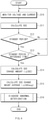
- FIG. 4 is a flowchart illustrating a control method of the battery management system 20 according to an embodiment of the present invention.
- the BMS 20 monitors the voltage, current, and the like of the battery cell 11 and/or the battery module 10 through various sensors such as a voltage measurement unit 111 and a current measurement unit 113 (S10).
- the SOC calculation unit 110 calculates the SOC of each of the plurality of battery cells 11 based on the monitored values such as voltage and current, and using the above-described methods (S11). Operations S10 and S11 may be performed in real time.
- the BMS 20 determines whether the battery pack 1 is in a standby period while performing operations S10 and S11 (S12).
- the standby period may be a pause period in which charging and discharging of the battery pack 1 is not performed.
- the BMS 20 determines that the battery pack 1 is not in the standby period in operation S12, it returns to operation S10 and repeats the operations in operations S10 and S11. On the other hand, when the BMS 20 determines that the battery pack 1 is in the standby period in operation S12, it is determined whether the standby period lasts longer than the reference time (S13).
- the reference time may be a time at which each battery cell 11 can measure that the SOC is significantly changed by self-discharge.
- the change amount calculation unit 120 calculates, for each of the plurality of battery cells 11, an SOC change amount ⁇ SOC, which is a change amount of the calculated SOC during a preset period (S14). In addition, the change amount calculation unit 120 calculates the SOC change amount average ⁇ SOCavg, which is an average of the SOC change amount ⁇ SOC of the entire plurality of battery cells 11 (S15).
- the abnormal deterioration diagnosis unit 130 diagnoses the abnormal deterioration of each of the plurality of battery cells 11 using the SOC change amount ⁇ SOC and the SOC change amount average ⁇ SOCavg calculated in steps S14 and S15 (S16).
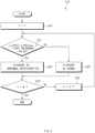
- FIG. 5 is a flowchart illustrating an example of a method for diagnosing abnormal deterioration in the control method of the battery management system 20 of FIG. 4 .
- n represents the order of the battery cells, and it is assumed that N number of battery cells 11 are included in the battery module 10.
- the abnormal deterioration of the battery cell 11 can be accurately diagnosed by the configuration of the BMS 20 and the control method thereof as described above.
- the effects of the embodiments of the present invention will be described with reference to test data measured on the battery cells.
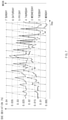
- FIGS. 7 to 9 are graphs showing test data for battery cells.
- FIG. 7 is illustrated based on data obtained by measuring the SOC of each battery cell in an actual battery module including a plurality of battery cells.
- the graph (upper graph) indicated by a circle is a graph showing the difference ( ⁇ SOC(Max-Min)) between the SOCs of the battery cells having the maximum SOC and the battery cells having the minimum SOC among battery cells.
- the graph (lower graph) indicated by a triangle is a graph showing the difference ( ⁇ SOC(Avg-Min)) between the average SOC of the battery cells and the SOC of the battery cell having the minimum SOC.
- ⁇ SOC (Max-Min) and ⁇ SOC (Avg-Min) values did not increase significantly from Monday afternoon to Saturday morning.
- ⁇ SOC (Max-Min) and ⁇ SOC (Avg-Min) values increased significantly. This is because a battery cell with a minimum SOC is a battery cell that has undergone abnormal deterioration, so the amount of self-discharge is larger than that of a normal battery cell.
- FIG. 8 shows a change amount of each battery cell itself in the rest state in the graph of FIG. 7 .
- the determination section of the change amount is from 8 AM on Saturday to 8 AM on Monday.
- the issue cell is indicated by a solid line
- the comparison cell is indicated by a dashed-dotted line
- the Avg is indicated by a broken line.
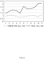
- FIG. 9 is a graph showing ( ⁇ SOC / ⁇ SOCavg) values calculated and shown as described in FIGS. 2 and 5 with respect to the values in [Table 1].
- the graph indicated by a solid line is a graph obtained by dividing the SOC change amount of the issue cell by the SOC change amount average
- the graph indicated by the dashed-dotted line is a graph obtained by dividing the SOC change amount of the comparison cell by the SOC change amount average.
- the value for the issue cell is greater than the value for the comparison cell over the entire period.
- the value obtained by dividing the change amount of the SOC of each battery cell by the average of the SOC change amount of all battery cells is more than a predetermined reference value, it can be immediately diagnosed as abnormally deteriorated battery cells.
- a predetermined reference value For example, in the case of this example, if the reference value is set to 2 and the ( ⁇ SOC / ⁇ SOCavg) value is 2 or more, it can be diagnosed as an abnormally deteriorated battery cell.
- these reference values are only examples and may be set to other values.
- diagnosis is performed using the SOC change amount and the SOC change amount average by self-discharge in the rest state of the battery cell. Therefore, there is no need to meet specific conditions such as charging or discharging the battery cells to a specific voltage for diagnosis. In other words, it is possible to diagnose abnormal deterioration of a battery cell regardless of voltages of a plurality of battery cells. And there is no need to charge or discharge at a specific C-rate. In addition, abnormal deterioration of the battery cell is diagnosed using the SOC, not the voltage affected by the temperature and the C-rate at the end of charging/discharging.
- FIG. 6 is a flowchart illustrating another example of a method for diagnosing abnormal deterioration in the control method of the battery management system of FIG. 4 .
- n represents the order of the battery cells, and it is assumed that N number of battery cells 11 are included in the battery module 10.
- the reference value is set to about 1.3, and the ( ⁇ SOC / ⁇ SOCavg) value is 1.3 or higher, it can be diagnosed as abnormally deteriorated battery cells.
- the comparison cell there is a case close to 1.3 (11th week), but it is temporary, so it can be expected that the value of 1.3 or more is difficult to be maintained for a certain period of time. Therefore, even if it temporarily exceeds the reference value, it is not immediately diagnosed as abnormally deteriorated battery cells, thereby preventing misdiagnosis.
- FIG. 10 is a hardware configuration diagram of the battery management system 20.
- the BMS 20 may include a controller (MCU) 210, a memory 220, an input/output interface 230, and a communication interface 240.
- MCU controller
- the BMS 20 may include a controller (MCU) 210, a memory 220, an input/output interface 230, and a communication interface 240.
- the MCU 210 performs processing of various operations and calculations in the BMS 20 and control of each component.
- the memory 220 an operating system program and a program for performing the functions of the BMS 20 are recorded. That is, a program describing an algorithm for performing abnormal deterioration diagnosis according to embodiments of the present invention may be stored in the memory 220.
- the memory 220 may include volatile memory and nonvolatile memory. For example, at least one of various storage media such as a semiconductor memory such as RAM, ROM, and flash memory, a magnetic disk, and an optical disk may be used as the memory 220.
- the memory 220 may be a memory built in the MCU 210 or an additional memory installed separately from the MCU 210.
- the input/output interface 230 performs input/output of various input signals and output signals.
- the MCU 210 included in the BMS 20 may receive signals from various sensors through the input/output interface 230.
- the communication interface 240 is a component capable of communicating with the outside in a wired and/or wireless manner.
- the MCU 210 executes a program stored in the memory 220 such that a module that performs functions of the SOC calculation unit 110, the change amount calculation unit 120, and the abnormal deterioration diagnosis unit 130 may be implemented.
- the memory 220 may function as the storage unit 140.
- the MCU 210 may operate together with the input/output interface 230 to perform functions as the voltage measurement unit 111 and the current measurement unit 123.
- the MCU 210 may operate with the communication interface 240 to perform a function as the communication unit 150.
- the terms “include”, “compose”, or “have” as described above means that the corresponding component can be intrinsic, unless otherwise stated, so that it should be interpreted that other components may be further included, not excluded. All terms, including technical or scientific terms, can be interpreted as having the same meaning as generally understood by a person skilled in the art to which the present invention belongs, unless otherwise defined. Generally used terms, such as predefined terms, should be interpreted as being consistent with the contextual meaning of the related art, and are not to be interpreted in an ideal or excessively formal sense, unless explicitly defined in the present invention.
Landscapes
- Physics & Mathematics (AREA)
- General Physics & Mathematics (AREA)
- Secondary Cells (AREA)
- Charge And Discharge Circuits For Batteries Or The Like (AREA)
- Tests Of Electric Status Of Batteries (AREA)
Abstract
Description
- The present invention claims the benefit of priority based on
Korean Patent Application No. 10-2019-0156065 filed on November 28, 2019 - The present invention relates to an apparatus and method for diagnosing abnormal deterioration of battery cells.
- Recently, with the spread of electronic devices such as smartphones and the development of electric vehicles, research on secondary batteries as a power source has also been actively conducted. The secondary battery is provided in the form of a battery pack including a battery module in which a plurality of battery cells are connected in series and/or in parallel, and a battery management system (BMS) that manages the operation of the battery module.
- The battery management system monitors the state of the battery cell and determines whether an abnormality has occurred in the battery cell. Among them, the abnormal deterioration of the battery was diagnosed through State of Health (SOH), which is a parameter representing characteristics related to life, such as the capacity and resistance deterioration of the battery. However, the SOH value calculated through the existing modeling techniques and algorithms has an error of 5% or more when compared with the actual state. Therefore, the conventional diagnosis method using the SOH value as it is did not have high reliability in diagnosing abnormal deterioration of the battery. Actually, in the past, the SOH value was mainly used to check the trend of the state change of the battery cell.
- The present invention has been made in consideration of such a problem, and an object of the present invention is to provide an apparatus and method for diagnosing battery cell abnormality deterioration, which has high reliability and does not significantly increase the complexity of the configuration compared to the conventional one.
- In order to solve the above technical problems, according to an aspect of the embodiments of the present disclosure, a battery cell abnormal deterioration diagnosis apparatus includes: an SOC calculation unit configured to calculate a state of charge (SOC) of a plurality of battery cells; a change amount calculation unit configured to calculate, for each of the plurality of battery cells, an SOC change amount that is a change amount of the calculated SOC during a preset period and an SOC change amount average that is an average of the SOC change amount of all the plurality of battery cells; and an abnormal deterioration diagnosis unit configured to diagnose abnormal deterioration of each of the plurality of battery cells using the SOC change amount and the SOC change amount average.
- According to another feature of this embodiment of the present disclosure, the abnormal deterioration diagnosis unit may diagnose a battery cell whose (SOC change amount/SOC change amount average) value is greater than or equal to a reference value as an abnormally deteriorated battery cell.
- According to another feature of this embodiment of the present disclosure, the abnormal deterioration diagnosis unit may diagnose a battery cell that is maintained for more than a reference period with a (SOC change amount/SOC change amount average) value equal to or greater than the reference value as an abnormally deteriorated battery cell.
- According to another feature of this embodiment of the present disclosure, the change amount calculation unit may calculate the SOC change amount and the SOC change amount average by using the SOC calculated by the SOC calculation unit during the standby period of the plurality of battery cells.
- According to another feature of this embodiment of the present disclosure, the abnormal deterioration diagnosis unit may diagnose whether the battery cell is abnormally deteriorated regardless of voltages of the plurality of battery cells.
- According to another feature of this embodiment of the present disclosure, the change amount calculation unit may calculate an SOC change amount due to self-discharge during the standby period as the SOC change amount.
- According to another feature of this embodiment of the present disclosure, the change amount calculation unit periodically may calculate the SOC change amount and the SOC change amount average.
- According to another feature of this embodiment of the present disclosure, the SOC calculation unit may include a voltage measurement unit for measuring a voltage of each of the plurality of battery cells, and calculate an SOC of each of the plurality of battery cells based on the voltage measured by the voltage measurement unit.
- According to another feature of this embodiment of the present disclosure, the SOC calculation unit may include a current measurement unit that measures a current charged and discharged in the plurality of battery cells, and a timer that measures a time during which the current is charged and discharged, and calculate an SOC of each of the plurality of battery cells based on a current measured by the current measurement unit and a time measured by the timer.
- In order to solve the above technical problem, according to an aspect of the embodiments of the present disclosure, a battery cell abnormal deterioration diagnosis method includes: calculating a state of charge (SOC) of a plurality of battery cells; calculating, for each of the plurality of battery cells, an SOC change amount that is a change amount of the calculated SOC during a preset period; calculating an SOC change amount average that is an average of SOC change amounts of all of the plurality of battery cells; and diagnosing whether each of the plurality of battery cells is abnormally deteriorated using the SOC change amount and the SOC change amount average.
- According to another feature of this embodiment of the present disclosure, the diagnosing whether each of the plurality of battery cells is abnormally deteriorated may include: calculating a (SOC change amount/SOC change amount average) value; comparing the calculated value with a reference value; and diagnosing a battery cell having the (SOC change amount/SOC change amount average) value equal to or greater than the reference value as an abnormally deteriorated battery cell.
- Due to the above configuration, it is possible to accurately diagnose abnormal deterioration of the battery cells.
-
-
FIG. 1 is a view showing the configuration of a battery pack including a battery management system. -
FIG. 2 is a block diagram showing functions of a battery management system according to an embodiment of the present invention. -
FIG. 3 is a block diagram showing the configuration of a state of charge calculation unit according to another embodiment of the present invention. -
FIG. 4 is a flowchart illustrating a control method of a battery management system according to an embodiment of the present invention. -
FIG. 5 is a flowchart illustrating an example of a method for diagnosing abnormal degradation in the control method of the battery management system ofFIG. 4 . -
FIG. 6 is a flowchart illustrating another example of a method for diagnosing abnormal deterioration in the control method of the battery management system ofFIG. 4 . -
FIGS. 7 to 9 are graphs showing test data for battery cells. -
FIG. 10 is a hardware configuration diagram of a battery management system. - Hereinafter, various embodiments of the present invention will be described in detail with reference to the accompanying drawings. In this document, the same reference numerals are used for the same components in the drawings, and duplicate descriptions for the same components are omitted.
- For various embodiments of the present invention disclosed in this document, specific structural or functional descriptions are exemplified only for the purpose of explaining an embodiment of the present invention, and various embodiments of the present invention may be implemented in various forms and should not be construed as being limited to the embodiments described in this document.
- The terms such as "1st", "2nd", "first", "second", and the like used herein may refer to modifying various different elements of various embodiments of the present disclosure, but do not limit the elements. For example, a first component may be referred to as a second component and vice versa without departing from the technical scope of the present invention.
- Terms used herein is for the purpose of describing particular example embodiments only and is not intended to be limiting of the scope of other embodiments. The terms of a singular form may include plural forms unless they have a clearly different meaning in the context.
-
FIG. 1 is a view showing the configuration of abattery pack 1 including abattery management system 20. - Referring to
FIG. 1 , thebattery pack 1 includes abattery module 10 composed of one or more battery cells and capable of being charged and discharged, aswitching unit 30 connected in series to the + terminal side or the - terminal side of thebattery module 10 to control the charge/discharge current flow of thebattery module 10, and a battery management system 20 (hereinafter referred to as a 'BMS') that monitors the voltage, current, temperature, and the like of the battery cell and/or thebattery module 10 to control and manage the prevention of overcharge and overdischarge. - The
battery module 10 includes one ormore battery cells 11 that can be charged and discharged. Thebattery cell 11 may be a lithium ion (Li-ion) battery, a lithium ion polymer (Li-ion polymer) battery, a nickel cadmium (Ni-Cd) battery, a nickel hydrogen (Ni-MH) battery, and the like, but is not limited thereto. - The
BMS 20 may control the operation of theswitching unit 30 to control charging and discharging of thebattery module 10. In addition, theBMS 20 may monitor the voltage, current, temperature, and the like of thebattery module 10 and/or eachbattery cell 11 included in thebattery module 10. In addition, for monitoring by theBMS 20, sensors or various measurement modules (not shown) may be additionally installed at any location of thebattery module 10, or the charge/discharge path, or thebattery pack 1. TheBMS 20 may calculate parameters indicating the state of thebattery module 10, for example, SOC or SOH, based on the measurement values of the monitored voltage, current, and temperature. - The
BMS 20 controls and manages the overall operation of thebattery pack 1. For this, the BMS 20 may include various components such as a microcomputer as a controller that executes a program and controls the overall operation of theBMS 20, input/output devices such as sensors and measurement means, and other peripheral circuits. - In addition, the
BMS 20 may calculate the state of charge of each thebattery cell 11 and diagnose whether each thebattery cell 11 is abnormally deteriorated using the calculated state of charge. In particular, theBMS 20 according to the present embodiment may diagnose whether each battery cell is abnormally deteriorated based on the average of the change amount of the state of charge and the change amount of the state of charge of each of the plurality ofbattery cells 11 included in thebattery module 10. Details on the diagnosis of abnormal degeneration of theBMS 20 will be described later. - The
switching unit 30 is a component for controlling current flow for charging or discharging of thebattery module 10, and a relay or a magnetic contactor may be used. Alternatively, a semiconductor switching element such as a MOSFET may be used as theswitching unit 30. - The
battery pack 1 may be further communicatively connected to an external upper-level controller 2. That is, thebattery pack 1 may transmit various data for thebattery pack 1 to the upper-level controller 2 and receive control signals for the operation of thebattery pack 1 from the upper-level controller 2. The upper-level controller 2 may be a vehicle controller for controlling the operation of the vehicle when thebattery pack 1 is mounted in an electric vehicle. The upper-level controller 2 may be a rack BMS that manages a plurality of battery modules or a BMS that controls the overall operation of an energy storage device (ESS) when thebattery pack 1 is used in the ESS. -
FIG. 2 is a block diagram showing functions of aBMS 20 according to an embodiment of the present invention. - Referring to
FIG. 2 , theBMS 20 may include a state ofcharge calculation unit 110, a changeamount calculation unit 120, an abnormaldeterioration diagnosis unit 130, astorage unit 140, and acommunication unit 150. - The state of
charge calculation unit 110 calculates the state of charge (SOC) of each of the plurality ofbattery cells 11. In this embodiment, theSOC calculation unit 110 may include avoltage measurement unit 111 to calculate the SOC. Thevoltage measurement unit 111 may be a voltage sensor that measures voltages of each of the plurality ofbattery cells 11 included in thebattery module 10. In addition, theSOC calculation unit 110 calculates an SOC of each of the plurality ofbattery cells 11 based on the voltages of each of the plurality ofbattery cells 11 measured by thevoltage measurement unit 111. In this case, theSOC calculation unit 110 may calculate an SOC based on a table indicating a relationship between a voltage and an SOC. For example, thestorage unit 140 may store in advance a table indicating the relationship between the voltage and the SOC, and theSOC calculation unit 110 may calculate the SOC of each of the plurality ofbattery cells 11 by referring to the corresponding table. However, this is an example, and in addition to using a table representing the relationship between the voltage and the SOC, various methods may be used, such as directly calculating the SOC from the voltage using a formula. In addition, in the present embodiment, it has been described that only the voltage value is used to calculate the SOC, but is not limited thereto. For example, in order to calculate the SOC, in addition to the voltage value, other parameters that affect the SOC, such as the temperature of thebattery cell 11 and/or thebattery pack 1, the type of thebattery cell 11, and the usage time, may be additionally considered. - The
SOC calculation unit 110 may monitor the plurality ofbattery modules 10 in real time. Accordingly, theSOC calculation unit 110 can measure the voltage value of thebattery cell 11 in real time, and also calculate the SOC in real time. - The change
amount calculation unit 120 calculates an SOC change amount, which is a change amount for a preset period of the SOC calculated by theSOC calculation unit 110, for each of the plurality ofbattery cells 11. The preset period may mean a case in which thebattery pack 1 is in a standby period. That is, the changeamount calculation unit 120 may calculate the SOC change amount by using the SOC calculated by theSOC calculation unit 110 during the standby period of the plurality ofbattery cells 11. - The change
amount calculation unit 120 also calculates an average of the SOC change amount, which is an average of the SOC change amounts of all of the plurality ofbattery cells 11. When calculating the SOC change amount during the standby period of the plurality ofbattery cells 11, the changeamount calculation unit 120 similarly may calculate an average of the SOC change amount for the standby period using the calculated SOC change amount. - The SOC change amount calculated by the change
amount calculation unit 120 may be a change amount of the SOC due to self-discharge during the standby period of each of the plurality ofbattery cells 11. Also, in the same manner, the average SOC change amount calculated by the changeamount calculation unit 120 may also be an average of the SOC change amount due to self-discharge during the standby period of the plurality ofbattery cells 11. - Meanwhile, the standby period may be set periodically. Accordingly, the change
amount calculation unit 120 may repeatedly calculate the SOC change amount and the SOC change amount average for each standby period that occurs periodically. However, this is exemplary, and the standby period may be appropriately set according to the environment in which thebattery pack 1 is installed, such as ESS or electric vehicle. The abnormaldeterioration diagnosis unit 130 diagnoses the abnormal deterioration of each of the plurality ofbattery cells 11 using the SOC change amount and SOC change amount average calculated by the changeamount calculation unit 120. - As one method of diagnosing abnormal deterioration, the abnormal
deterioration diagnosis unit 130 diagnoses thebattery cells 11 satisfying condition1 as abnormally deteriorated battery cells. - (SOC change amount/SOC change amount average) ≥ first reference value: condition1
- That is, it is not simply to diagnose abnormal deterioration by directly using the SOC value, the SOH value, or the SOC change amount of each
battery cell 11. In other words, the present embodiment is characterized in diagnosing abnormal deterioration using the change amount of the SOC of thebattery cell 11 and the 'average of the SOC change amount'. Specifically, when the SOC change amount of thespecific battery cell 11 with respect to the SOC change amount average is equal to or greater than the first reference value, it is determined that thebattery cell 11 has abnormal deterioration. - As another method of diagnosing abnormal deterioration, the abnormal
deterioration diagnosis unit 130 diagnoses thebattery cells 11 satisfying condition2 and condition3 as abnormally deteriorated battery cells. - That is, when the SOC change amount of the
specific battery cell 11 with respect to the SOC change amount average is equal to or greater than the second reference value and is maintained for more than the reference period, it is determined that thebattery cell 11 has been abnormally deteriorated. Here, the second reference value may be a value smaller than the first reference value. - The
storage unit 140 may store various programs and data necessary for the operation of theBMS 20. As described above, thestorage unit 140 may store a table indicating a relationship between the SOC and the voltage for calculating the SOC of thebattery cell 11. In addition, thestorage unit 140 may store data such as the first reference value, the second reference value, and the reference period described above. - The
communication unit 150 may transmit various information on thebattery cell 11, thebattery module 10 and/or thebattery pack 1 to the upper-level controller 2 as necessary. Also, thecommunication unit 150 may receive a control signal for controlling thebattery pack 1 from the upper-level controller 2. When the abnormaldeterioration diagnosis unit 130 detects an abnormally deteriorated battery cell among the plurality ofbattery cells 11, thecommunication unit 150 may transmit the information to the upper-level controller 2. -
FIG. 3 is a block diagram showing the configuration of anSOC calculation unit 110 according to another embodiment of the present invention. - Referring to
FIG. 3 , theSOC calculation unit 110 may include acurrent measurement unit 113 and atimer 115 to calculate an SOC. - The
current measurement unit 113 measures currents charged and discharged in the plurality ofbattery cells 11. Thecurrent measurement unit 113 may be a current sensor provided on a charge/discharge path of thebattery pack 1. - The
timer 115 measures the time during which the current is charged and discharged. That is, thetimer 115 may measure a time from start to end of charging and a time from start to end of discharging of thebattery pack 1, respectively. - The
SOC calculation unit 110 calculates the SOC of each of the plurality ofbattery cells 11 based on the current measured by thecurrent measurement unit 113 and the time measured by thetimer 115. Specifically, theSOC calculation unit 110 can calculate the SOC of thebattery cell 11 by integrating the measured current. In the present embodiment, it has been described that only the current value and the time are used, but the present invention is not limited thereto. For example, in order to calculate the SOC, in addition to the current value and the time, other parameters that affect the SOC, such as the temperature of thebattery cell 11 and/or thebattery pack 1, the type of thebattery cell 11, and the usage time, may be additionally considered. -
FIG. 4 is a flowchart illustrating a control method of thebattery management system 20 according to an embodiment of the present invention. - Referring to
FIG. 4 , theBMS 20 monitors the voltage, current, and the like of thebattery cell 11 and/or thebattery module 10 through various sensors such as avoltage measurement unit 111 and a current measurement unit 113 (S10). TheSOC calculation unit 110 calculates the SOC of each of the plurality ofbattery cells 11 based on the monitored values such as voltage and current, and using the above-described methods (S11). Operations S10 and S11 may be performed in real time. - Meanwhile, the
BMS 20 determines whether thebattery pack 1 is in a standby period while performing operations S10 and S11 (S12). The standby period may be a pause period in which charging and discharging of thebattery pack 1 is not performed. - If the
BMS 20 determines that thebattery pack 1 is not in the standby period in operation S12, it returns to operation S10 and repeats the operations in operations S10 and S11. On the other hand, when theBMS 20 determines that thebattery pack 1 is in the standby period in operation S12, it is determined whether the standby period lasts longer than the reference time (S13). The reference time may be a time at which eachbattery cell 11 can measure that the SOC is significantly changed by self-discharge. - When the
BMS 20 determines that the standby period does not last longer than the reference time, that is, when thebattery pack 1 is charged and discharged again within the reference time, the process returns to operation S10. On the other hand, if theBMS 20 determines that the standby period lasts longer than the reference time, the changeamount calculation unit 120 calculates, for each of the plurality ofbattery cells 11, an SOC change amount ΔSOC, which is a change amount of the calculated SOC during a preset period (S14). In addition, the changeamount calculation unit 120 calculates the SOC change amount average ΔSOCavg, which is an average of the SOC change amount ΔSOC of the entire plurality of battery cells 11 (S15). - The abnormal
deterioration diagnosis unit 130 diagnoses the abnormal deterioration of each of the plurality ofbattery cells 11 using the SOC change amount ΔSOC and the SOC change amount average ΔSOCavg calculated in steps S14 and S15 (S16). - Hereinafter, a specific method of diagnosing abnormal deterioration of the
battery cell 11 by the abnormaldeterioration diagnosis unit 130 will be described. -
FIG. 5 is a flowchart illustrating an example of a method for diagnosing abnormal deterioration in the control method of thebattery management system 20 ofFIG. 4 . - Referring to
FIG. 5 , as starting from the first battery cell (S20), a value obtained by dividing the calculated SOC change amount ΔSOCn of thebattery cell 11 by the SOC change amount average ΔSOCavg is compared with the first reference value (S21). n represents the order of the battery cells, and it is assumed that N number ofbattery cells 11 are included in thebattery module 10. - In operation S21, if (ΔSOCn / ΔSOCavg) is greater than or equal to the first reference value, the corresponding
battery cell 11 is diagnosed as an abnormally deteriorated battery cell (S22). On the other hand, if (ΔSOCn / ΔSOCavg) is less than the first reference value in operation S21, the correspondingbattery cell 11 is diagnosed as a normal battery cell (S23). - Then, it is determined whether abnormal deterioration diagnosis has been performed on all the battery cells 11 (S24). When the abnormal deterioration diagnosis is not performed on all the
battery cells 11, the process proceeds to the next battery cell 11 (S25). On the other hand, when abnormal deterioration diagnosis is performed for allbattery cells 11, the abnormal deterioration diagnosis is terminated. In this case, after waiting until the next standby period, the above-described operation will be repeated again when the next standby period arrives. - The abnormal deterioration of the
battery cell 11 can be accurately diagnosed by the configuration of theBMS 20 and the control method thereof as described above. In this regard, the effects of the embodiments of the present invention will be described with reference to test data measured on the battery cells. -
FIGS. 7 to 9 are graphs showing test data for battery cells. - First,
FIG. 7 is illustrated based on data obtained by measuring the SOC of each battery cell in an actual battery module including a plurality of battery cells. Among them, the graph (upper graph) indicated by a circle is a graph showing the difference (ΔSOC(Max-Min)) between the SOCs of the battery cells having the maximum SOC and the battery cells having the minimum SOC among battery cells. And the graph (lower graph) indicated by a triangle is a graph showing the difference (ΔSOC(Avg-Min)) between the average SOC of the battery cells and the SOC of the battery cell having the minimum SOC. - In this test, the battery was maintained in a rest state from Saturday morning to Monday afternoon. That is, the battery module was not used during the weekend. And, from Monday afternoon to Saturday morning, charging and discharging were continuously performed.
- Due to the above conditions, ΔSOC (Max-Min) and ΔSOC (Avg-Min) values did not increase significantly from Monday afternoon to Saturday morning. On the other hand, in the rest state from Saturday afternoon to Monday morning, it was confirmed that both ΔSOC (Max-Min) and ΔSOC (Avg-Min) values increased significantly. This is because a battery cell with a minimum SOC is a battery cell that has undergone abnormal deterioration, so the amount of self-discharge is larger than that of a normal battery cell.
- However, as determined from this graph, because the values of ΔSOC(Max-Min) and ΔSOC(Avg-Min) fluctuate greatly, the values of ΔSOC (Max-Min) and ΔSOC (Avg-Min) cannot accurately determine whether a specific battery cell has abnormal deterioration. It is only possible to determine the abnormal deterioration of the battery cell only by the transition of ΔSOC (Max-Min) and ΔSOC (Avg-Min) values.
-
FIG. 8 shows a change amount of each battery cell itself in the rest state in the graph ofFIG. 7 . The determination section of the change amount is from 8 AM on Saturday to 8 AM on Monday. - Specific measurement values are as follows.
[Table 1] Week Comparison Cell Issue Cell Avg Comparison Cell/Avg Issue Cell/ Avg 1 0.0048 0.0082 0.0059 0.813559322 1.389830508 2 0.008 0.0131 0.0076 1.052631579 1.723684211 3 0.008 0.0148 0.0076 1.052631579 1.947368421 4 0.008 0.0174 0.0093 0.860215054 1.870967742 5 0.0114 0.0223 0.0159 0.716981132 1.402515723 6 0.0064 0.0215 0.0083 0.771084337 2.590361446 7 0.0083 0.02 0.0093 0.892473118 2.150537634 8 0.0115 0.0255 0.0117 0.982905983 2.179487179 9 0.0091 0.0222 0.0093 0.978494624 2.387096774 10 0.0048 0.0204 0.0067 0.716417910 3.044776119 11 0.0081 0.0213 0.0068 1.191176471 3.132352941 - Among the above measurement values, the issue cell is indicated by a solid line, the comparison cell is indicated by a dashed-dotted line, and the Avg is indicated by a broken line.
- Looking at the graphs of
FIG. 8 , it was confirmed that the self-discharge increased in the rest state after the 5th week in the issue cell (i.e., abnormal deterioration cell). However, similarly, the comparison cell and Avg values also increased at the 5th week. - Therefore, there were concerns of misdiagnosis when diagnosing abnormal deterioration simply by increasing the amount of self-discharge.
-
FIG. 9 is a graph showing (ΔSOC / ΔSOCavg) values calculated and shown as described inFIGS. 2 and5 with respect to the values in [Table 1]. In the graph ofFIG. 9 , the graph indicated by a solid line is a graph obtained by dividing the SOC change amount of the issue cell by the SOC change amount average, and the graph indicated by the dashed-dotted line is a graph obtained by dividing the SOC change amount of the comparison cell by the SOC change amount average. - As can be seen from the graphs of
FIG. 9 , in the case of the issue cell, the value rapidly increased from the 6th week. In addition, it can be seen that the value for the issue cell is greater than the value for the comparison cell over the entire period. - That is, as in the embodiments of the present invention, if the value obtained by dividing the change amount of the SOC of each battery cell by the average of the SOC change amount of all battery cells is more than a predetermined reference value, it can be immediately diagnosed as abnormally deteriorated battery cells. For example, in the case of this example, if the reference value is set to 2 and the (ΔSOC / ΔSOCavg) value is 2 or more, it can be diagnosed as an abnormally deteriorated battery cell. However, it will be apparent to a person skilled in the art that these reference values are only examples and may be set to other values.
- According to the embodiments of the present invention, diagnosis is performed using the SOC change amount and the SOC change amount average by self-discharge in the rest state of the battery cell. Therefore, there is no need to meet specific conditions such as charging or discharging the battery cells to a specific voltage for diagnosis. In other words, it is possible to diagnose abnormal deterioration of a battery cell regardless of voltages of a plurality of battery cells. And there is no need to charge or discharge at a specific C-rate. In addition, abnormal deterioration of the battery cell is diagnosed using the SOC, not the voltage affected by the temperature and the C-rate at the end of charging/discharging.
- That is, in embodiments of the present invention, it is possible to diagnose abnormal deterioration by a ratio of the change amount of the SOC in the rest state to the average of the SOC change amount regardless of charging and discharging. And by using this method, it is possible to improve the reliability of control and management of the
BMS 20 by lowering the probability of false diagnosis of abnormal deterioration. -
FIG. 6 is a flowchart illustrating another example of a method for diagnosing abnormal deterioration in the control method of the battery management system ofFIG. 4 . - Referring to
FIG. 6 , as starting from the first battery cell (S30), a value obtained by dividing the calculated SOC change amount ΔSOCn of thebattery cell 11 by the SOC change amount average ΔSOCavg is compared with the second reference value (S31). n represents the order of the battery cells, and it is assumed that N number ofbattery cells 11 are included in thebattery module 10. - In operation S31, if (ΔSOCn / ΔSOCavg) is greater than or equal to the second reference value, it is determined whether the corresponding
battery cell 11 maintains a state equal to or greater than the second reference value for more than a reference period (S32). When the state above the second reference value is maintained for longer than the reference period, the corresponding battery cell is diagnosed as an abnormally deteriorated battery cell (S33). On the other hand, if (ΔSOCn / ΔSOCavg) is less than the first reference value in operation S31 or less than the reference period in operation S32, the correspondingbattery cell 11 is diagnosed as a normal battery cell (S34). Then, it is determined whether abnormal deterioration diagnosis has been performed on all the battery cells 11 (S35). When the abnormal deterioration diagnosis is not performed on all thebattery cells 11, the process proceeds to the next battery cell 11 (S36). On the other hand, when abnormal deterioration diagnosis is performed for allbattery cells 11, the abnormal deterioration diagnosis is terminated. In this case, after waiting until the next standby period, the above-described operation will be repeated again when the next standby period arrives. - In the present embodiment, it is not determined that a battery cell is an abnormally deteriorated battery cell when (ΔSOCn / ΔSOCavg) of the
battery cell 11 is simply more than a reference value, and it is determined that such a state is maintained for a reference period or longer. As a result, it is possible to prevent a false diagnosis in which the case where (ΔSOCn / ΔSOCavg) temporarily exceeds the reference value is diagnosed as abnormally deteriorated battery cells. This second reference value may be set to a lower value than the first reference value. For example, in the case of [Table 1], if the reference value is set to about 1.3, and the (ΔSOC / ΔSOCavg) value is 1.3 or higher, it can be diagnosed as abnormally deteriorated battery cells. In the case of the comparison cell, there is a case close to 1.3 (11th week), but it is temporary, so it can be expected that the value of 1.3 or more is difficult to be maintained for a certain period of time. Therefore, even if it temporarily exceeds the reference value, it is not immediately diagnosed as abnormally deteriorated battery cells, thereby preventing misdiagnosis. -
FIG. 10 is a hardware configuration diagram of thebattery management system 20. - Referring to
FIG. 10 , theBMS 20 may include a controller (MCU) 210, amemory 220, an input/output interface 230, and acommunication interface 240. - The
MCU 210 performs processing of various operations and calculations in theBMS 20 and control of each component. - In the
memory 220, an operating system program and a program for performing the functions of theBMS 20 are recorded. That is, a program describing an algorithm for performing abnormal deterioration diagnosis according to embodiments of the present invention may be stored in thememory 220. Thememory 220 may include volatile memory and nonvolatile memory. For example, at least one of various storage media such as a semiconductor memory such as RAM, ROM, and flash memory, a magnetic disk, and an optical disk may be used as thememory 220. Thememory 220 may be a memory built in theMCU 210 or an additional memory installed separately from theMCU 210. - The input/
output interface 230 performs input/output of various input signals and output signals. For example, theMCU 210 included in theBMS 20 may receive signals from various sensors through the input/output interface 230. - The
communication interface 240 is a component capable of communicating with the outside in a wired and/or wireless manner. - The
MCU 210 executes a program stored in thememory 220 such that a module that performs functions of theSOC calculation unit 110, the changeamount calculation unit 120, and the abnormaldeterioration diagnosis unit 130 may be implemented. Thememory 220 may function as thestorage unit 140. TheMCU 210 may operate together with the input/output interface 230 to perform functions as thevoltage measurement unit 111 and the current measurement unit 123. In addition, theMCU 210 may operate with thecommunication interface 240 to perform a function as thecommunication unit 150. - In addition, the terms "include", "compose", or "have" as described above means that the corresponding component can be intrinsic, unless otherwise stated, so that it should be interpreted that other components may be further included, not excluded. All terms, including technical or scientific terms, can be interpreted as having the same meaning as generally understood by a person skilled in the art to which the present invention belongs, unless otherwise defined. Generally used terms, such as predefined terms, should be interpreted as being consistent with the contextual meaning of the related art, and are not to be interpreted in an ideal or excessively formal sense, unless explicitly defined in the present invention.
- The above description is merely illustrative of the technical idea of the present invention, and those skilled in the art to which the present invention pertains will be able to make various modifications and variations without departing from the essential characteristics of the present invention. Therefore, the embodiments disclosed in the present invention are not intended to limit the technical spirit of the present invention, but to explain, and the scope of the technical spirit of the present invention is not limited by these embodiments. The scope of protection of the present invention should be construed according to the following claims, and all technical ideas falling within the scope of the same shall be construed as falling within the scope of the present invention.
Claims (11)
- A battery cell abnormal deterioration diagnosis apparatus comprising:an SOC calculation unit configured to calculate a state of charge (SOC) of a plurality of battery cells;a change amount calculation unit configured to calculate, for each of the plurality of battery cells, an SOC change amount that is a change amount of the calculated SOC during a preset period and an SOC change amount average that is an average of the SOC change amount of all the plurality of battery cells; andan abnormal deterioration diagnosis unit configured to diagnose abnormal deterioration of each of the plurality of battery cells using the SOC change amount and the SOC change amount average.
- The apparatus of claim 1, wherein the abnormal deterioration diagnosis unit diagnoses a battery cell whose (SOC change amount/SOC change amount average) value is greater than or equal to a reference value as an abnormally deteriorated battery cell.
- The apparatus of claim 1, wherein the abnormal deterioration diagnosis unit diagnoses a battery cell that is maintained for more than a reference period with a (SOC change amount/SOC change amount average) value equal to or greater than the reference value as an abnormally deteriorated battery cell.
- The apparatus of claim 1, wherein the change amount calculation unit calculates the SOC change amount and the SOC change amount average by using the SOC calculated by the SOC calculation unit during the standby period of the plurality of battery cells.
- The apparatus of claim 4, wherein the abnormal deterioration diagnosis unit diagnoses whether the battery cell is abnormally deteriorated regardless of voltages of the plurality of battery cells.
- The apparatus of claim 4, wherein the change amount calculation unit calculates an SOC change amount due to self-discharge during the standby period as the SOC change amount.
- The apparatus of claim 4, wherein the change amount calculation unit periodically calculates the SOC change amount and the SOC change amount average.
- The apparatus of claim 1, wherein the SOC calculation unit comprises a voltage measurement unit for measuring a voltage of each of the plurality of battery cells, and
calculates an SOC of each of the plurality of battery cells based on the voltage measured by the voltage measurement unit. - The apparatus of claim 1, wherein the SOC calculation unit comprises a current measurement unit that measures a current charged and discharged in the plurality of battery cells, and a timer that measures a time during which the current is charged and discharged, and
calculates an SOC of each of the plurality of battery cells based on a current measured by the current measurement unit and a time measured by the timer. - A battery cell abnormal deterioration diagnosis method comprising:calculating a state of charge (SOC) of a plurality of battery cells;calculating, for each of the plurality of battery cells, an SOC change amount that is a change amount of the calculated SOC during a preset period;calculating an SOC change amount average that is an average of SOC change amounts of all of the plurality of battery cells; anddiagnosing whether each of the plurality of battery cells is abnormally deteriorated using the SOC change amount and the SOC change amount average.
- The method of claim 10, wherein the diagnosing whether each of the plurality of battery cells is abnormally deteriorated comprises:calculating a (SOC change amount/SOC change amount average) value;comparing the calculated value with a reference value; anddiagnosing a battery cell having the (SOC change amount/SOC change amount average) value equal to or greater than the reference value as an abnormally deteriorated battery cell.
Applications Claiming Priority (2)
| Application Number | Priority Date | Filing Date | Title |
|---|---|---|---|
| KR1020190156065A KR102781907B1 (en) | 2019-11-28 | 2019-11-28 | Apparatus and method for diagnosing abnormal degratdated battery cell |
| PCT/KR2020/009802 WO2021107323A1 (en) | 2019-11-28 | 2020-07-24 | Apparatus and method for diagnosing abnormal degradation of battery cell |
Publications (3)
| Publication Number | Publication Date |
|---|---|
| EP3961234A1 true EP3961234A1 (en) | 2022-03-02 |
| EP3961234A4 EP3961234A4 (en) | 2022-08-10 |
| EP3961234B1 EP3961234B1 (en) | 2024-11-20 |
Family
ID=76128791
Family Applications (1)
| Application Number | Title | Priority Date | Filing Date |
|---|---|---|---|
| EP20892272.4A Active EP3961234B1 (en) | 2019-11-28 | 2020-07-24 | Apparatus and method for diagnosing abnormal degradation of battery cell |
Country Status (7)
| Country | Link |
|---|---|
| US (1) | US11815558B2 (en) |
| EP (1) | EP3961234B1 (en) |
| JP (1) | JP7403775B2 (en) |
| KR (1) | KR102781907B1 (en) |
| CN (1) | CN113994224A (en) |
| ES (1) | ES2996904T3 (en) |
| WO (1) | WO2021107323A1 (en) |
Families Citing this family (12)
| Publication number | Priority date | Publication date | Assignee | Title |
|---|---|---|---|---|
| KR20220167847A (en) * | 2021-06-14 | 2022-12-22 | 주식회사 엘지에너지솔루션 | Battery management system, battery pack, electric vehicle and battery management method |
| US20250096336A1 (en) * | 2022-03-28 | 2025-03-20 | Iontra Inc | Electrodynamic parameters |
| US20250216462A1 (en) * | 2022-05-04 | 2025-07-03 | Lg Energy Solution, Ltd. | Battery diagnosis method and battery system for providing the same |
| KR102864746B1 (en) * | 2022-09-13 | 2025-09-25 | 주식회사 엘지에너지솔루션 | Battery management apparatus and operating method of the same |
| KR20240040991A (en) * | 2022-09-22 | 2024-03-29 | 주식회사 엘지에너지솔루션 | Apparatus and method for analysing test of battery's long time characteristics |
| WO2024063418A2 (en) * | 2022-09-23 | 2024-03-28 | 주식회사 엘지에너지솔루션 | Battery diagnosis device and battery diagnosis method |
| ES3044041T3 (en) * | 2022-10-12 | 2025-11-26 | Lg Energy Solution Ltd | Battery diagnosis apparatus and method for leakage current detection |
| KR20240147302A (en) * | 2023-03-31 | 2024-10-08 | 주식회사 엘지에너지솔루션 | Apparatus for managing battery and operating method of the same |
| JP2024148768A (en) * | 2023-04-06 | 2024-10-18 | 株式会社デンソー | Battery diagnostic device and program |
| KR20250015476A (en) * | 2023-07-25 | 2025-02-03 | 주식회사 엘지에너지솔루션 | Battery diagnosis apparatus, battery diagnosis method and battery diagnosis system |
| KR20250155851A (en) * | 2024-04-24 | 2025-10-31 | 주식회사 엘지에너지솔루션 | Apparatus and method for battery diagnostic |
| WO2025263295A1 (en) * | 2024-06-18 | 2025-12-26 | パナソニックIpマネジメント株式会社 | Battery diagnosis system, battery diagnosis method, and battery diagnosis program |
Family Cites Families (37)
| Publication number | Priority date | Publication date | Assignee | Title |
|---|---|---|---|---|
| JP3649135B2 (en) | 2001-02-20 | 2005-05-18 | 日産自動車株式会社 | Abnormality detection device for battery pack |
| JP2003243042A (en) | 2002-02-12 | 2003-08-29 | Toyota Motor Corp | Apparatus and method for detecting degree of deterioration of lithium battery constituting assembled battery |
| JP4019815B2 (en) | 2002-06-26 | 2007-12-12 | 日産自動車株式会社 | Abnormality diagnosis apparatus and method for assembled battery |
| JP4377164B2 (en) | 2003-06-10 | 2009-12-02 | 株式会社日立製作所 | Power storage device abnormality detection method, power storage device abnormality detection device, and power storage system |
| JP4806558B2 (en) | 2005-10-18 | 2011-11-02 | プライムアースEvエナジー株式会社 | Secondary battery control device and secondary battery deterioration judgment method |
| JP2008008861A (en) * | 2006-06-30 | 2008-01-17 | Toyota Motor Corp | Battery performance rank diagnosis apparatus and battery performance rank diagnosis program |
| JP4890977B2 (en) * | 2006-07-04 | 2012-03-07 | 富士重工業株式会社 | Battery deterioration calculation device |
| KR100970841B1 (en) | 2008-08-08 | 2010-07-16 | 주식회사 엘지화학 | Battery capacity deterioration estimation apparatus and method using battery voltage behavior |
| JP2010114966A (en) * | 2008-11-04 | 2010-05-20 | Toyota Motor Corp | Power control device for vehicle |
| JP2010216914A (en) | 2009-03-16 | 2010-09-30 | Tokyo Electric Power Co Inc:The | Method for creating index of battery life standard, and method for determining secondary battery life |
| KR101057542B1 (en) | 2010-01-26 | 2011-08-17 | 에스비리모티브 주식회사 | Battery Management System and Its Driving Method |
| US8749201B2 (en) * | 2010-10-05 | 2014-06-10 | GM Global Technology Operations LLC | Battery pack capacity learn algorithm |
| KR101182431B1 (en) | 2010-10-12 | 2012-09-12 | 삼성에스디아이 주식회사 | Battery pack, controlling method of the same, and power storage system including the battery pack |
| JP5469625B2 (en) * | 2011-03-01 | 2014-04-16 | 株式会社日立製作所 | Battery system |
| US9118191B2 (en) | 2011-08-29 | 2015-08-25 | Samsung Sdi Co., Ltd. | Cell balancing method, cell balancing device, and energy storage system including the cell balancing device |
| JP6017790B2 (en) * | 2012-02-01 | 2016-11-02 | トヨタ自動車株式会社 | Power storage system |
| WO2014132321A1 (en) * | 2013-02-26 | 2014-09-04 | 株式会社 日立製作所 | Power source device |
| JP5821899B2 (en) * | 2013-06-04 | 2015-11-24 | トヨタ自動車株式会社 | Battery deterioration detection device |
| EP2957921B1 (en) | 2013-07-04 | 2018-04-04 | LG Chem, Ltd. | Method and system for estimating soc of battery |
| JP2015158416A (en) | 2014-02-24 | 2015-09-03 | 日産自動車株式会社 | Apparatus for estimating soc of secondary battery, and soc estimation method |
| JP6314043B2 (en) * | 2014-06-26 | 2018-04-18 | プライムアースEvエナジー株式会社 | Storage battery inspection method and storage battery inspection device |
| AU2015358776B2 (en) * | 2014-12-10 | 2020-07-02 | Gs Yuasa International Ltd. | Energy storage device state estimation device and energy storage device state estimation method |
| GB2545493A (en) | 2015-12-18 | 2017-06-21 | Moog Unna Gmbh | Wind turbine diagnostic apparatus |
| JP6299783B2 (en) | 2016-02-15 | 2018-03-28 | セイコーエプソン株式会社 | Electro-optical device and electronic apparatus |
| JP2018055783A (en) * | 2016-09-26 | 2018-04-05 | 株式会社豊田自動織機 | Power storage device |
| KR102035678B1 (en) | 2016-11-01 | 2019-10-23 | 주식회사 엘지화학 | Method and appratus for caculating state of health(soh) of a battery |
| KR102035679B1 (en) * | 2016-11-29 | 2019-10-23 | 주식회사 엘지화학 | Method and system for caculating state of health(soh) of a battery |
| KR102350920B1 (en) * | 2017-01-09 | 2022-01-13 | 한화디펜스 주식회사 | device for detecting the state of charge of a battery |
| WO2018235496A1 (en) | 2017-06-19 | 2018-12-27 | 日本ゼオン株式会社 | POWER CONTROL DEVICE AND POWER GENERATOR |
| JP6658689B2 (en) | 2017-07-18 | 2020-03-04 | トヨタ自動車株式会社 | Battery system and vehicle equipped with battery system |
| KR102439932B1 (en) | 2017-07-26 | 2022-09-05 | 삼성전자주식회사 | Method and apparatus for detecting battery fault |
| KR101949449B1 (en) | 2017-11-07 | 2019-02-18 | 주식회사 스마트이앤엠 | Method and apparatus for estimating battery life |
| CN108196190B (en) | 2017-11-20 | 2020-02-18 | 上海理工大学 | A method for on-line fault diagnosis of battery pack |
| JP6911747B2 (en) * | 2017-12-25 | 2021-07-28 | トヨタ自動車株式会社 | Battery information processing device, battery manufacturing support device, assembled battery, battery information processing method, and assembled battery manufacturing method |
| CN111868539A (en) * | 2018-03-20 | 2020-10-30 | 株式会社杰士汤浅国际 | Deterioration estimation device, computer program, and degradation estimation method |
| CN109541471B (en) * | 2018-11-27 | 2020-05-29 | 安徽江淮汽车集团股份有限公司 | Method for diagnosing loosening fault of battery sampling line |
| CN109687548B (en) * | 2018-12-28 | 2022-11-04 | 中国船舶重工集团公司第七一九研究所 | A battery pack supplementary electric active equalization device |
-
2019
- 2019-11-28 KR KR1020190156065A patent/KR102781907B1/en active Active
-
2020
- 2020-07-24 US US17/615,646 patent/US11815558B2/en active Active
- 2020-07-24 CN CN202080041311.6A patent/CN113994224A/en active Pending
- 2020-07-24 WO PCT/KR2020/009802 patent/WO2021107323A1/en not_active Ceased
- 2020-07-24 ES ES20892272T patent/ES2996904T3/en active Active
- 2020-07-24 EP EP20892272.4A patent/EP3961234B1/en active Active
- 2020-07-24 JP JP2021571008A patent/JP7403775B2/en active Active
Also Published As
| Publication number | Publication date |
|---|---|
| US20220317196A1 (en) | 2022-10-06 |
| ES2996904T3 (en) | 2025-02-13 |
| US11815558B2 (en) | 2023-11-14 |
| WO2021107323A1 (en) | 2021-06-03 |
| EP3961234B1 (en) | 2024-11-20 |
| KR102781907B1 (en) | 2025-03-18 |
| JP2022535766A (en) | 2022-08-10 |
| KR20210066609A (en) | 2021-06-07 |
| EP3961234A4 (en) | 2022-08-10 |
| JP7403775B2 (en) | 2023-12-25 |
| CN113994224A (en) | 2022-01-28 |
Similar Documents
| Publication | Publication Date | Title |
|---|---|---|
| US11815558B2 (en) | Apparatus and method for diagnosing abnormal degradated battery cell | |
| US11965936B2 (en) | Battery diagnosis apparatus and method | |
| EP3961233B1 (en) | Battery cell diagnosis device and method | |
| US12040458B2 (en) | Slave BMS inspection system and method | |
| KR102729621B1 (en) | Apparatus and method for detecting failure of battery | |
| EP4428553A1 (en) | Battery diagnosis apparatus, battery diagnosis method and battery diagnosis system | |
| US20250364828A1 (en) | Apparatus, method and computer program for updating current pattern for quick charge | |
| KR102717609B1 (en) | Apparatus and method for diagnosing battery | |
| KR20240162881A (en) | Battery management apparatus and operating method of the same | |
| KR20240166322A (en) | Apparatus for managing battery and operating method of the same | |
| US20250123332A1 (en) | Battery management apparatus and operating method of the same | |
| EP4560336B1 (en) | Abnormally deteriorated cell detection apparatus and method | |
| KR102899567B1 (en) | Battery management apparatus and operating method of the same | |
| US20260100429A1 (en) | Overheating diagnosis method, overheating diagnosis apparatus and battery system providing the same | |
| KR20250097496A (en) | Battery management apparatus and operating method of the same | |
| KR20250014601A (en) | Battery management apparatus and operating method of the same | |
| KR20250019892A (en) | Apparatus for managing battery and operating method of the same | |
| KR20250092893A (en) | Battery diagnosis apparatus and operating method of the same | |
| KR20240170273A (en) | Battery diagnostic device and method of operation thereof | |
| KR20250120700A (en) | Battery diagnosis apparatus and operating method of the same |
Legal Events
| Date | Code | Title | Description |
|---|---|---|---|
| STAA | Information on the status of an ep patent application or granted ep patent |
Free format text: STATUS: THE INTERNATIONAL PUBLICATION HAS BEEN MADE |
|
| PUAI | Public reference made under article 153(3) epc to a published international application that has entered the european phase |
Free format text: ORIGINAL CODE: 0009012 |
|
| STAA | Information on the status of an ep patent application or granted ep patent |
Free format text: STATUS: REQUEST FOR EXAMINATION WAS MADE |
|
| 17P | Request for examination filed |
Effective date: 20211125 |
|
| AK | Designated contracting states |
Kind code of ref document: A1 Designated state(s): AL AT BE BG CH CY CZ DE DK EE ES FI FR GB GR HR HU IE IS IT LI LT LU LV MC MK MT NL NO PL PT RO RS SE SI SK SM TR |
|
| RAP3 | Party data changed (applicant data changed or rights of an application transferred) |
Owner name: LG ENERGY SOLUTION, LTD. |
|
| A4 | Supplementary search report drawn up and despatched |
Effective date: 20220712 |
|
| RIC1 | Information provided on ipc code assigned before grant |
Ipc: G01R 31/396 20190101ALN20220706BHEP Ipc: G01R 31/387 20190101ALN20220706BHEP Ipc: G01R 31/392 20190101AFI20220706BHEP |
|
| DAV | Request for validation of the european patent (deleted) | ||
| DAX | Request for extension of the european patent (deleted) | ||
| GRAP | Despatch of communication of intention to grant a patent |
Free format text: ORIGINAL CODE: EPIDOSNIGR1 |
|
| STAA | Information on the status of an ep patent application or granted ep patent |
Free format text: STATUS: GRANT OF PATENT IS INTENDED |
|
| RIC1 | Information provided on ipc code assigned before grant |
Ipc: G01R 31/396 20190101ALN20240605BHEP Ipc: G01R 31/387 20190101ALN20240605BHEP Ipc: G01R 31/392 20190101AFI20240605BHEP |
|
| INTG | Intention to grant announced |
Effective date: 20240703 |
|
| P01 | Opt-out of the competence of the unified patent court (upc) registered |
Free format text: CASE NUMBER: APP_44510/2024 Effective date: 20240731 |
|
| GRAS | Grant fee paid |
Free format text: ORIGINAL CODE: EPIDOSNIGR3 |
|
| GRAA | (expected) grant |
Free format text: ORIGINAL CODE: 0009210 |
|
| STAA | Information on the status of an ep patent application or granted ep patent |
Free format text: STATUS: THE PATENT HAS BEEN GRANTED |
|
| AK | Designated contracting states |
Kind code of ref document: B1 Designated state(s): AL AT BE BG CH CY CZ DE DK EE ES FI FR GB GR HR HU IE IS IT LI LT LU LV MC MK MT NL NO PL PT RO RS SE SI SK SM TR |
|
| REG | Reference to a national code |
Ref country code: GB Ref legal event code: FG4D |
|
| REG | Reference to a national code |
Ref country code: CH Ref legal event code: EP |
|
| REG | Reference to a national code |
Ref country code: DE Ref legal event code: R096 Ref document number: 602020041852 Country of ref document: DE |
|
| REG | Reference to a national code |
Ref country code: IE Ref legal event code: FG4D |
|
| REG | Reference to a national code |
Ref country code: ES Ref legal event code: FG2A Ref document number: 2996904 Country of ref document: ES Kind code of ref document: T3 Effective date: 20250213 |
|
| REG | Reference to a national code |
Ref country code: LT Ref legal event code: MG9D |
|
| REG | Reference to a national code |
Ref country code: NL Ref legal event code: MP Effective date: 20241120 |
|
| REG | Reference to a national code |
Ref country code: HU Ref legal event code: AG4A Ref document number: E069372 Country of ref document: HU |
|
| PG25 | Lapsed in a contracting state [announced via postgrant information from national office to epo] |
Ref country code: PT Free format text: LAPSE BECAUSE OF FAILURE TO SUBMIT A TRANSLATION OF THE DESCRIPTION OR TO PAY THE FEE WITHIN THE PRESCRIBED TIME-LIMIT Effective date: 20250320 Ref country code: IS Free format text: LAPSE BECAUSE OF FAILURE TO SUBMIT A TRANSLATION OF THE DESCRIPTION OR TO PAY THE FEE WITHIN THE PRESCRIBED TIME-LIMIT Effective date: 20250320 Ref country code: HR Free format text: LAPSE BECAUSE OF FAILURE TO SUBMIT A TRANSLATION OF THE DESCRIPTION OR TO PAY THE FEE WITHIN THE PRESCRIBED TIME-LIMIT Effective date: 20241120 |
|
| PG25 | Lapsed in a contracting state [announced via postgrant information from national office to epo] |
Ref country code: NL Free format text: LAPSE BECAUSE OF FAILURE TO SUBMIT A TRANSLATION OF THE DESCRIPTION OR TO PAY THE FEE WITHIN THE PRESCRIBED TIME-LIMIT Effective date: 20241120 Ref country code: FI Free format text: LAPSE BECAUSE OF FAILURE TO SUBMIT A TRANSLATION OF THE DESCRIPTION OR TO PAY THE FEE WITHIN THE PRESCRIBED TIME-LIMIT Effective date: 20241120 |
|
| REG | Reference to a national code |
Ref country code: AT Ref legal event code: MK05 Ref document number: 1744039 Country of ref document: AT Kind code of ref document: T Effective date: 20241120 |
|
| PG25 | Lapsed in a contracting state [announced via postgrant information from national office to epo] |
Ref country code: BG Free format text: LAPSE BECAUSE OF FAILURE TO SUBMIT A TRANSLATION OF THE DESCRIPTION OR TO PAY THE FEE WITHIN THE PRESCRIBED TIME-LIMIT Effective date: 20241120 |
|
| PG25 | Lapsed in a contracting state [announced via postgrant information from national office to epo] |
Ref country code: NO Free format text: LAPSE BECAUSE OF FAILURE TO SUBMIT A TRANSLATION OF THE DESCRIPTION OR TO PAY THE FEE WITHIN THE PRESCRIBED TIME-LIMIT Effective date: 20250220 |
|
| PG25 | Lapsed in a contracting state [announced via postgrant information from national office to epo] |
Ref country code: GR Free format text: LAPSE BECAUSE OF FAILURE TO SUBMIT A TRANSLATION OF THE DESCRIPTION OR TO PAY THE FEE WITHIN THE PRESCRIBED TIME-LIMIT Effective date: 20250221 Ref country code: AT Free format text: LAPSE BECAUSE OF FAILURE TO SUBMIT A TRANSLATION OF THE DESCRIPTION OR TO PAY THE FEE WITHIN THE PRESCRIBED TIME-LIMIT Effective date: 20241120 Ref country code: LV Free format text: LAPSE BECAUSE OF FAILURE TO SUBMIT A TRANSLATION OF THE DESCRIPTION OR TO PAY THE FEE WITHIN THE PRESCRIBED TIME-LIMIT Effective date: 20241120 |
|
| PG25 | Lapsed in a contracting state [announced via postgrant information from national office to epo] |
Ref country code: PL Free format text: LAPSE BECAUSE OF FAILURE TO SUBMIT A TRANSLATION OF THE DESCRIPTION OR TO PAY THE FEE WITHIN THE PRESCRIBED TIME-LIMIT Effective date: 20241120 |
|
| PG25 | Lapsed in a contracting state [announced via postgrant information from national office to epo] |
Ref country code: RS Free format text: LAPSE BECAUSE OF FAILURE TO SUBMIT A TRANSLATION OF THE DESCRIPTION OR TO PAY THE FEE WITHIN THE PRESCRIBED TIME-LIMIT Effective date: 20250220 |
|
| PG25 | Lapsed in a contracting state [announced via postgrant information from national office to epo] |
Ref country code: SM Free format text: LAPSE BECAUSE OF FAILURE TO SUBMIT A TRANSLATION OF THE DESCRIPTION OR TO PAY THE FEE WITHIN THE PRESCRIBED TIME-LIMIT Effective date: 20241120 |
|
| PG25 | Lapsed in a contracting state [announced via postgrant information from national office to epo] |
Ref country code: DK Free format text: LAPSE BECAUSE OF FAILURE TO SUBMIT A TRANSLATION OF THE DESCRIPTION OR TO PAY THE FEE WITHIN THE PRESCRIBED TIME-LIMIT Effective date: 20241120 |
|
| PGFP | Annual fee paid to national office [announced via postgrant information from national office to epo] |
Ref country code: GB Payment date: 20250624 Year of fee payment: 6 |
|
| PGFP | Annual fee paid to national office [announced via postgrant information from national office to epo] |
Ref country code: BE Payment date: 20250407 Year of fee payment: 6 |
|
| PG25 | Lapsed in a contracting state [announced via postgrant information from national office to epo] |
Ref country code: EE Free format text: LAPSE BECAUSE OF FAILURE TO SUBMIT A TRANSLATION OF THE DESCRIPTION OR TO PAY THE FEE WITHIN THE PRESCRIBED TIME-LIMIT Effective date: 20241120 |
|
| PGFP | Annual fee paid to national office [announced via postgrant information from national office to epo] |
Ref country code: FR Payment date: 20250624 Year of fee payment: 6 |
|
| PG25 | Lapsed in a contracting state [announced via postgrant information from national office to epo] |
Ref country code: RO Free format text: LAPSE BECAUSE OF FAILURE TO SUBMIT A TRANSLATION OF THE DESCRIPTION OR TO PAY THE FEE WITHIN THE PRESCRIBED TIME-LIMIT Effective date: 20241120 |
|
| PG25 | Lapsed in a contracting state [announced via postgrant information from national office to epo] |
Ref country code: SK Free format text: LAPSE BECAUSE OF FAILURE TO SUBMIT A TRANSLATION OF THE DESCRIPTION OR TO PAY THE FEE WITHIN THE PRESCRIBED TIME-LIMIT Effective date: 20241120 |
|
| PG25 | Lapsed in a contracting state [announced via postgrant information from national office to epo] |
Ref country code: CZ Free format text: LAPSE BECAUSE OF FAILURE TO SUBMIT A TRANSLATION OF THE DESCRIPTION OR TO PAY THE FEE WITHIN THE PRESCRIBED TIME-LIMIT Effective date: 20241120 |
|
| PG25 | Lapsed in a contracting state [announced via postgrant information from national office to epo] |
Ref country code: IT Free format text: LAPSE BECAUSE OF FAILURE TO SUBMIT A TRANSLATION OF THE DESCRIPTION OR TO PAY THE FEE WITHIN THE PRESCRIBED TIME-LIMIT Effective date: 20241120 |
|
| PGFP | Annual fee paid to national office [announced via postgrant information from national office to epo] |
Ref country code: HU Payment date: 20250721 Year of fee payment: 6 |
|
| REG | Reference to a national code |
Ref country code: DE Ref legal event code: R097 Ref document number: 602020041852 Country of ref document: DE |
|
| PG25 | Lapsed in a contracting state [announced via postgrant information from national office to epo] |
Ref country code: SE Free format text: LAPSE BECAUSE OF FAILURE TO SUBMIT A TRANSLATION OF THE DESCRIPTION OR TO PAY THE FEE WITHIN THE PRESCRIBED TIME-LIMIT Effective date: 20241120 |
|
| PLBE | No opposition filed within time limit |
Free format text: ORIGINAL CODE: 0009261 |
|
| STAA | Information on the status of an ep patent application or granted ep patent |
Free format text: STATUS: NO OPPOSITION FILED WITHIN TIME LIMIT |
|
| PGFP | Annual fee paid to national office [announced via postgrant information from national office to epo] |
Ref country code: ES Payment date: 20250822 Year of fee payment: 6 |
|
| PGFP | Annual fee paid to national office [announced via postgrant information from national office to epo] |
Ref country code: DE Payment date: 20250624 Year of fee payment: 6 |
|
| 26N | No opposition filed |
Effective date: 20250821 |
|
| REG | Reference to a national code |
Ref country code: CH Ref legal event code: H13 Free format text: ST27 STATUS EVENT CODE: U-0-0-H10-H13 (AS PROVIDED BY THE NATIONAL OFFICE) Effective date: 20260224 |
|
| PG25 | Lapsed in a contracting state [announced via postgrant information from national office to epo] |
Ref country code: LU Free format text: LAPSE BECAUSE OF NON-PAYMENT OF DUE FEES Effective date: 20250724 |
|
| PG25 | Lapsed in a contracting state [announced via postgrant information from national office to epo] |
Ref country code: CH Free format text: LAPSE BECAUSE OF NON-PAYMENT OF DUE FEES Effective date: 20250731 |