EP3961205A1 - Method for inspecting porosity or foreign debris in a structure - Google Patents
Method for inspecting porosity or foreign debris in a structure Download PDFInfo
- Publication number
- EP3961205A1 EP3961205A1 EP21196138.8A EP21196138A EP3961205A1 EP 3961205 A1 EP3961205 A1 EP 3961205A1 EP 21196138 A EP21196138 A EP 21196138A EP 3961205 A1 EP3961205 A1 EP 3961205A1
- Authority
- EP
- European Patent Office
- Prior art keywords
- angle
- ramp
- signal
- porosity
- signals
- Prior art date
- Legal status (The legal status is an assumption and is not a legal conclusion. Google has not performed a legal analysis and makes no representation as to the accuracy of the status listed.)
- Withdrawn
Links
- 238000000034 method Methods 0.000 title claims description 96
- 238000002604 ultrasonography Methods 0.000 claims abstract description 97
- 230000004044 response Effects 0.000 claims abstract description 96
- 239000002131 composite material Substances 0.000 claims description 45
- 230000008878 coupling Effects 0.000 claims description 10
- 238000010168 coupling process Methods 0.000 claims description 10
- 238000005859 coupling reaction Methods 0.000 claims description 10
- 239000000463 material Substances 0.000 claims description 10
- XLYOFNOQVPJJNP-UHFFFAOYSA-N water Substances O XLYOFNOQVPJJNP-UHFFFAOYSA-N 0.000 claims description 5
- 238000007689 inspection Methods 0.000 description 49
- 238000010586 diagram Methods 0.000 description 5
- 230000003746 surface roughness Effects 0.000 description 5
- 230000008859 change Effects 0.000 description 3
- 230000005540 biological transmission Effects 0.000 description 2
- 238000005070 sampling Methods 0.000 description 2
- 230000001419 dependent effect Effects 0.000 description 1
- 230000001066 destructive effect Effects 0.000 description 1
- 238000001514 detection method Methods 0.000 description 1
- 238000004519 manufacturing process Methods 0.000 description 1
- 238000012986 modification Methods 0.000 description 1
- 230000004048 modification Effects 0.000 description 1
- 230000008569 process Effects 0.000 description 1
- 230000035945 sensitivity Effects 0.000 description 1
- 230000037303 wrinkles Effects 0.000 description 1
Images





Classifications
-
- G—PHYSICS
- G01—MEASURING; TESTING
- G01N—INVESTIGATING OR ANALYSING MATERIALS BY DETERMINING THEIR CHEMICAL OR PHYSICAL PROPERTIES
- G01N15/00—Investigating characteristics of particles; Investigating permeability, pore-volume or surface-area of porous materials
- G01N15/08—Investigating permeability, pore-volume, or surface area of porous materials
- G01N15/088—Investigating volume, surface area, size or distribution of pores; Porosimetry
-
- G—PHYSICS
- G01—MEASURING; TESTING
- G01N—INVESTIGATING OR ANALYSING MATERIALS BY DETERMINING THEIR CHEMICAL OR PHYSICAL PROPERTIES
- G01N29/00—Investigating or analysing materials by the use of ultrasonic, sonic or infrasonic waves; Visualisation of the interior of objects by transmitting ultrasonic or sonic waves through the object
- G01N29/04—Analysing solids
- G01N29/11—Analysing solids by measuring attenuation of acoustic waves
-
- G—PHYSICS
- G01—MEASURING; TESTING
- G01N—INVESTIGATING OR ANALYSING MATERIALS BY DETERMINING THEIR CHEMICAL OR PHYSICAL PROPERTIES
- G01N29/00—Investigating or analysing materials by the use of ultrasonic, sonic or infrasonic waves; Visualisation of the interior of objects by transmitting ultrasonic or sonic waves through the object
- G01N29/04—Analysing solids
- G01N29/043—Analysing solids in the interior, e.g. by shear waves
-
- G—PHYSICS
- G01—MEASURING; TESTING
- G01N—INVESTIGATING OR ANALYSING MATERIALS BY DETERMINING THEIR CHEMICAL OR PHYSICAL PROPERTIES
- G01N2291/00—Indexing codes associated with group G01N29/00
- G01N2291/01—Indexing codes associated with the measuring variable
- G01N2291/015—Attenuation, scattering
-
- G—PHYSICS
- G01—MEASURING; TESTING
- G01N—INVESTIGATING OR ANALYSING MATERIALS BY DETERMINING THEIR CHEMICAL OR PHYSICAL PROPERTIES
- G01N2291/00—Indexing codes associated with group G01N29/00
- G01N2291/02—Indexing codes associated with the analysed material
- G01N2291/023—Solids
- G01N2291/0231—Composite or layered materials
-
- G—PHYSICS
- G01—MEASURING; TESTING
- G01N—INVESTIGATING OR ANALYSING MATERIALS BY DETERMINING THEIR CHEMICAL OR PHYSICAL PROPERTIES
- G01N2291/00—Indexing codes associated with group G01N29/00
- G01N2291/02—Indexing codes associated with the analysed material
- G01N2291/028—Material parameters
- G01N2291/0289—Internal structure, e.g. defects, grain size, texture
-
- G—PHYSICS
- G01—MEASURING; TESTING
- G01N—INVESTIGATING OR ANALYSING MATERIALS BY DETERMINING THEIR CHEMICAL OR PHYSICAL PROPERTIES
- G01N2291/00—Indexing codes associated with group G01N29/00
- G01N2291/04—Wave modes and trajectories
- G01N2291/044—Internal reflections (echoes), e.g. on walls or defects
-
- G—PHYSICS
- G01—MEASURING; TESTING
- G01N—INVESTIGATING OR ANALYSING MATERIALS BY DETERMINING THEIR CHEMICAL OR PHYSICAL PROPERTIES
- G01N2291/00—Indexing codes associated with group G01N29/00
- G01N2291/04—Wave modes and trajectories
- G01N2291/048—Transmission, i.e. analysed material between transmitter and receiver
-
- G—PHYSICS
- G01—MEASURING; TESTING
- G01N—INVESTIGATING OR ANALYSING MATERIALS BY DETERMINING THEIR CHEMICAL OR PHYSICAL PROPERTIES
- G01N2291/00—Indexing codes associated with group G01N29/00
- G01N2291/04—Wave modes and trajectories
- G01N2291/056—Angular incidence, angular propagation
-
- G—PHYSICS
- G01—MEASURING; TESTING
- G01N—INVESTIGATING OR ANALYSING MATERIALS BY DETERMINING THEIR CHEMICAL OR PHYSICAL PROPERTIES
- G01N2291/00—Indexing codes associated with group G01N29/00
- G01N2291/10—Number of transducers
- G01N2291/106—Number of transducers one or more transducer arrays
Definitions
- the present disclosure relates generally to inspecting structures, and more specifically, to structures with ramps. Yet more specifically, the present disclosure presents methods for ultrasonic inspection of portions of a structure beneath a ramp of the structure.
- Ultrasound is a non-destructive inspection method used in the inspection of structures, including composite structures. Ultrasonic inspections send ultrasonic signals into a structure and analyze ultrasonic ultrasound response signals to inspect the structure.
- Ultrasonic inspection is sensitive to structural geometry. To inspect a structure using ultrasound, it is desirable for the front surface and back surface of the structure to be parallel to each other. For ultrasonic inspection it is desirable for the front surface and the back surface to be substantially smooth.
- Structural designs having non-parallel surfaces or high surface roughness may be undesirably difficult to inspect with traditional ultrasonic inspection techniques. Therefore, it would be desirable to have a method and apparatus that takes into account at least some of the issues discussed above, as well as other possible issues.
- the illustrative embodiments recognize and take into account one or more different considerations. For example, the illustrative embodiments recognize and take into account that inspecting porosity in composite structures that are steeply angled/ramped, for example having greater than thirty degrees, is undesirably difficult. The illustrative embodiments recognize and take into account that currently, ply ramp areas that change at a rate less than 20:1 are inspected. Ply ramp areas that change at a rate less than 20:1 change at a rate less than three degrees. The illustrative embodiments recognize and take into account that structures with steeper ramps may be desirable.
- the illustrative embodiments recognize and take into account that inspection requirements may need to be modified when a ramp in the structure has an angle greater than three degrees.
- the illustrative embodiments recognize and take into account that modifying inspection requirements may impact design of the structure.
- the illustrative embodiments recognize and take into account that increasing inconsistency detection near the ramp can enable improved design of structures.
- the illustrative embodiments recognize and take into account that conventional ultrasonic inspections send signals into a structure at an angle perpendicular to a backwall, or second surface, of the structure.
- the illustrative embodiments recognize and take into account that for many structures, the signals may be sent into the structure substantially perpendicular to the first surface.
- the illustrative embodiments recognize and take into account that when a second surface is ramped or angled relative to a first surface, the signals may be directed at an angle relative to the first surface into the structure in order to be perpendicular to the second surface.
- the illustrative embodiments recognize and take into account that for gently ramped areas (20:1), the process is to steer an ultrasonic beam perpendicular to the surface to be inspected.
- the illustrative embodiments recognize and take into account that for a steep angle, only a fraction of the sound path inspects the area of interest. Also, the illustrative embodiments recognize and take into account that steering the beam at steep angles is more difficult than desired.
- ultrasonic inspection equipment 102 inspects structure 104.
- Structure 104 has ramp 106 and second ramp 108.
- Ramp 106 has first angle 110.
- First angle 110 is measured relative to first surface 112.
- First angle 110 is greater than three degrees.
- the ramp 106 forms an angle 110 between zero and thirty degrees with a line normal to the second surface 126.
- first angle 110 is equal to or greater than sixty degrees.
- Second ramp 108 has second angle 114.
- Second angle 114 is measured relative to first surface 112.
- Second angle 114 is greater than three degrees. In some illustrative examples, second angle 114 is equal to or greater than sixty degrees.
- structure 104 is formed of composite material 115.
- Structure 104 is formed by co-curing or co-bonding composite skin 116 and thick composite layup 118.
- Plurality of composite plies 120 are laid up to form composite skin 116.
- Second plurality of composite plies 122 of varying widths 124 are laid up to form thick composite layup 118.
- Composite skin 116 and thick composite layup 118 are either co-cured or co-bonded to form structure 104 with ramp 106.
- Ramp 106 and second surface 126 are formed by curing thick composite layup 118.
- Ramp 106 is created by varying widths 124 of second plurality of composite plies 122.
- Second ramp 108 is created by varying widths 124 of second plurality of composite plies 122.
- ultrasonic inspection equipment 102 sends signals 130 into structure 104 at angle 132.
- Angle 132 is substantially parallel to first angle 110.
- angle 132 is desirably the same as first angle 110.
- substantially parallel is within two degrees of another angle.
- angle 132 is within two degrees of first angle 110.
- ultrasonic inspection equipment 102 takes the form of transducer array 134.
- Transducer array 134 sends signals 130, such as signal 136, into structure 104 at angle 132 using mechanical angle adjuster 138 or electronic beam steering 140.
- Sending signals 130 and receiving ultrasound response signals 142 at transducer array 134 is referred to as "pulse echo inspection.”
- ultrasound response signals 142 are formed at second surface 126 and are received at transducer array 134.
- ultrasound response signal 144 is formed at second surface 126.
- Ultrasound response signal 144 has angle 146.
- Angle 146 is a reflection of angle 132 about a line normal to second surface 126.
- the reception of ultrasound response signals 142 takes into account angle 146.
- the reception of ultrasound response signals 142 is performed at an angle. This reception may be referred to as similar to "reverse" beam steering.
- the reception of ultrasound response signals is performed at a reflected angle to angle 132 either electronically or with a mechanical structure, such as a wedge.
- amplitude 150 of ultrasound response signal 144 is used to detect a porosity within structure 104 in the paths followed by signal 136 and ultrasound response signal 144.
- porosity 148 is detected for multiple locations beneath ramp 106.
- signals 130 are sent into different locations of structure 104 to detect porosity 148 for multiple locations beneath ramp 106.
- signals 130 are sent into different locations of structure 104 to detect porosity 148 for multiple locations beneath ramp 106.
- signals 130 are sent into different locations of structure 104 using a combination of stepping transducer array 134 across first surface 112 and using different transmitters of phased array 162.
- first angle 110 is a reflection of second angle 114.
- signals 130 and ultrasound response signals 142 may be used to detect porosity 152 within structure 104 beneath second ramp 108.
- angle 132 is not parallel to second angle 114
- angle 146 of ultrasound response signal 144 is parallel to second angle 114.
- signal 154 having angle 156 substantially parallel to second angle 114 is sent into structure 104 to detect porosity 152 within structure 104 beneath second ramp 108.
- ultrasound response signal 158 forms at second surface 126. Amplitude 160 of ultrasound response signal 158 is used to detect porosity 152 within structure 104 beneath second ramp 108.
- Ultrasound response signals 142 and ultrasound response signal 158 may be received by a transducer array 134, such as phased array 162.
- signals 130 are received by receiver 164.
- signal 136 is sent into structure 104, and signal 166 is received by receiver 164.
- signal 136 is sent into structure 104 using transmitter 168.
- Amplitude 170 of signal 166 received by receiver 164 may be used to detect porosity 148 within structure 104 beneath ramp 106.
- Receiving signal 166 at receiver 164 may be referred to as "through transmission" ultrasonic inspection.
- At least one of signals 130 and signal 154 are sent into structure 104 to inspect structure 104 beneath ramp 106 and second ramp 108.
- the phrase "at least one of,” when used with a list of items, means different combinations of one or more of the listed items may be used, and only one of each item in the list may be needed. In other words, "at least one of” means any combination of items and number of items may be used from the list, but not all of the items in the list are required.
- the item may be a particular object, a thing, or a category.
- “at least one of item A, item B, or item C” may include, without limitation, item A, item A and item B, or item B. This example also may include item A, item B, and item C, or item B and item C. Of course, any combination of these items may be present. In other examples, "at least one of” may be, for example, without limitation, two of item A, one of item B, and ten of item C; four of item B and seven of item C; or other suitable combinations.
- At least one of signals 130 or signal 154 are used to perform inspection sampling throughout structure 104.
- signals 130 may be used to perform sampling throughout structure 104 including portions beneath second surface 126.
- signals 172 are sent into structure 104 normal to second surface 126 in portions of structure that are not ramped.
- Ultrasound response signals 174 are received normal to second surface 126.
- Amplitude 176 of ultrasound response signals 174 is used to detect porosity 178 within structure 104 between second surface 126 and first surface 112 of structure 104.
- inspection environment 100 in Figure 1 is not meant to imply physical or architectural limitations to the manner in which an illustrative embodiment may be implemented.
- Other components in addition to or in place of the ones illustrated may be used. Some components may be unnecessary.
- the blocks are presented to illustrate some functional components. One or more of these blocks may be combined, divided, or combined and divided into different blocks when implemented in an illustrative embodiment.
- ramp 106 or second ramp 108 has significant variation in average surface roughness.
- ramp 106 has significant variation in surface roughness
- ramp 106 may be referred to as having a rough surface.
- second ramp 108 may be referred to as having a rough surface.
- ultrasonic inspection equipment 102 may be used to inspect for other types of inconsistencies.
- signals 130 from ultrasonic inspection equipment 102 may be used to inspect for foreign object debris.
- an associated time for ultrasound response signals 142 is used.
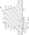
- FIG. 2 an illustration of a cross-sectional view of a composite structure is depicted in accordance with an illustrative embodiment.
- Structure 200 is a physical implementation of structure 104 of Figure 1 .
- Structure 200 has first surface 202 and second surface 204.
- Second surface 204 is parallel to first surface 202. Signals sent into first surface 202 travel in direction 206 and ultrasound response signals are reflected off of second surface 204. Ultrasonic inspection using signals normal to first surface 202 may be performed in region 208 of structure 200.
- First surface 202 is substantially planar. As depicted, second surface 204 is also substantially planar.
- Structure 200 includes ramp 210 and ramp 212.
- Ramp 210 has rough surface 214.
- Angle 216 of ramp 210 relative to second surface 204 is greater than sixty degrees.
- An angle of ramp 210 relative to a line normal to second surface 204 is thirty degrees or less. Due to rough surface 214 and angle 216, traditional ultrasonic inspection is not performed on structure 200 beneath ramp 210.
- Ramp 212 has rough surface 218. Angle 220 of ramp 212 relative to second surface 204 is greater than sixty degrees. An angle of ramp 212 relative to a line normal to second surface 204 is thirty degrees or less. Due to rough surface 218 and angle 220, traditional ultrasonic inspection is not performed on structure 200 beneath ramp 212.
- ramp 210 and ramp 212 may have any desirable angle relative to first surface 202.
- ramp 210 and ramp 212 are each sixty degrees or more from first surface 202.
- ramp 210 and a directed ultrasonic signal to inspect structure 200 below ramp 210 are each thirty degrees or less from a line normal to first surface 202.
- View 300 is an illustration of an ultrasonic inspection of structure 200 of Figure 2 .
- transducer array 302 sends signal 304 into first surface 202 of structure 200.
- Signal 304 is sent into structure 200 at angle 306 substantially parallel to ramp 210 of structure 200 using transducer array 302.
- signal 304 is sent into structure 200 at angle 306 using electronic beam steering.
- Transducer array 302 is a physical implementation of transducer array 134.
- Figure 3 depicts a "pulse echo inspection.”
- Transducer array 302 both sends signals, such as signal 304, and receives ultrasound response signals, such as ultrasound response signal 308.
- coupling material 313 couples transducer array 302 to structure 200.
- Coupling material 313 takes the form of water or any other desirable coupling material.
- Transducer array 302 sends signal 316 into coupling material 313.
- signal 316 reaches surface 202 of structure 200, signal 316 refracts to cause signal 304 to enter structure 200 at angle 306.
- Angle 306 is a refraction angle.
- Angle 306 is related to the array steering angle for signal 316 by Snell's law.
- the velocity of coupling material 313 is approximately half the velocity of structure 200. In these illustrative examples, angle 306 is roughly twice the array steering angle of signal 316.
- Ultrasound response signal 308 is formed at second surface 204 of structure 200.
- second surface 204 may be referred to as back wall 310.
- Ultrasound response signal 308 is received at transducer array 302.
- Ultrasound response signal 308 has angle 312 relative to first surface 202.
- Angle 312 is a reflection of angle 306 about line 314 normal to first surface 202.
- Ramp 210 forms an angle between zero and thirty degrees with line 314 normal to second surface 204.
- Ramp 212 forms an angle between zero and thirty degrees with line 314 normal to second surface 204.
- angle 306 and angle 312 are each greater than sixty degrees. Angle 306 and angle 312 are desirably greater than sixty degrees so that each of signal 304 and ultrasound response signal 308 are no more than thirty degrees relative to line 314 normal to first surface 202.
- ultrasound response signal 308 when ultrasound response signal 308 reaches surface 202 of structure 200, ultrasound response signal 308 is refracted to form response signal 318.
- Transducer array 302 receives ultrasound response signal 308 in the form of response signal 318 from coupling material 313.
- a porosity within structure 200 beneath ramp 210 can be detected from the amplitude of ultrasound response signal 308.
- the porosity within structure 200 along signal 304 may be detected using ultrasound response signal 308.
- porosity along signal 304 and porosity along ultrasound response signal 308 are assumed to be equal.
- an average porosity along signal 304 and along ultrasound response signal 308 is evaluated from the signal strength. The signal strength in the presence of porosity would decrease when compared to a porosity free zone.
- porosity along ultrasound response signal 308 is known from previous inspections.
- porosity along signal 304 is detected using ultrasound response signal 308 and the known porosity from previous inspections.
- Ultrasound response signal 308 travels through structure 200 beneath second surface 204. A porosity within structure 200 along the path of ultrasound response signal 308 may be detected using ultrasound response signal 308.
- View 400 is an illustration of an ultrasonic inspection of structure 200 of Figure 2 .
- transmitter 402 sends signal 404 into first surface 202 of structure 200.
- Signal 404 is sent into structure 200 at angle 406 substantially parallel to ramp 210 of structure 200 using transmitter 402.
- signal 404 is sent into structure 200 at angle 406 using electronic beam steering.
- signal 404 may be sent into structure 200 using a mechanical angle adjuster.
- Transmitter 402 is coupled to structure 200 using water 407 or other desirable coupling material.
- Receiver 408 is positioned at second surface 204 of structure 200. Receiver 408 receives signal 404 at angle 406. An amplitude of signal 404 is used to detect a porosity within structure 200 beneath ramp 210. Porosity within structure 200 along signal 404 can be detected from the amplitude of signal 404. Receiver 408 is coupled to structure 200 using water 409 or other desirable coupling material.
- transducer array 302 has moved in direction 502 relative to structure 200.
- transducer array 302 After receiving ultrasound response signal 308 in Figure 3 , transducer array 302 sends another signal into structure 200 at angle 306 to detect a porosity within another portion of structure 200 beneath ramp 210. In view 500, transducer array 302 has moved in direction 502 after receiving ultrasound response signal 308 in Figure 3 .
- transducer array 302 sends signal 504 into structure 200 at angle 306.
- Angle 306 is substantially parallel to ramp 210 of structure 200.
- signal 504 is sent into structure 200 at angle 306 using electronic beam steering.
- Ultrasound response signal 506 is formed at second surface 204 of structure 200. Ultrasound response signal 506 is received at transducer array 302. Ultrasound response signal 506 has angle 312 relative to first surface 202. Angle 312 is a reflection of angle 306.
- a porosity within structure 200 beneath ramp 210 can be detected from the amplitude of ultrasound response signal 506.
- the porosity within structure 200 along signal 504 may be detected using ultrasound response signal 506.
- porosity along signal 504 and porosity along ultrasound response signal 506 are assumed to be equal.
- an average porosity along signal 504 and along ultrasound response signal 506 is evaluated from the signal strength. The signal strength in the presence of porosity would decrease when compared to a porosity free zone.
- porosity along ultrasound response signal 506 is known from previous inspections.
- porosity along signal 504 is detected using ultrasound response signal 506 and the known porosity from previous inspections.
- Ultrasound response signal 506 travels through structure 200 beneath second surface 204. A porosity within structure 200 along the path of ultrasound response signal 506 may be detected using ultrasound response signal 506.
- transducer array 302 may be moved in direction 502 prior to sending another signal into structure 200.
- a different transmitting cell of transducer array 302 sends a signal into structure 200.
- a transmitting cell in direction 502 from transmitting cell 508 sends another signal in structure 200.
- signals may be introduced in a pulsed fashion across the area beneath ramp 210.
- transducer array 302 has moved in direction 502 relative to structure 200.
- transducer array 302 sends signal 602 into structure 200 at angle 306.
- Angle 306 is substantially parallel to ramp 210 of structure 200.
- Ramp 210 is a reflection of ramp 212 about a line normal to first surface 202.
- the absolute values of angle 216 and angle 220 are substantially the same. Accordingly, signals with substantially the same angle, angle 306 could be sent into structure 200 to detect porosity under both ramp 210 and ramp 212.
- angle 306 is a reflection of ramp 212.
- signal 602 is sent into structure 200 at angle 306 using electronic beam steering.
- Ultrasound response signal 604 is formed at second surface 204 of structure 200. Ultrasound response signal 604 is received at transducer array 302. Ultrasound response signal 604 has angle 312 relative to first surface 202. Angle 312 is a reflection of angle 306. Angle 312 of ultrasound response signal 604 is substantially parallel to ramp 212 of structure 200.
- a porosity within structure 200 beneath ramp 212 can be detected from the amplitude of ultrasound response signal 604.
- Ultrasound response signal 604 travels beneath ramp 212.
- the porosity within structure 200 along ultrasound response signal 604 may be detected using ultrasound response signal 604.
- Signal 602 travels through structure 200 beneath second surface 204.
- a porosity within structure 200 along the path of signal 602 may be detected using ultrasound response signal 604.
- transducer array 302 sends a signal having angle 312 relative to first surface 202 into structure 200.
- an ultrasound response signal having angle 306 is received at transducer array 302.
- signals parallel to ramp 212 also referred to as a second ramp, are used to detect porosity below ramp 212.
- signals having angle 312 are used when ramp 212 and ramp 210 are not reflections of each other.
- signals sent into structure 200 having angle 312 may be used to detect porosity beneath ramp 212 when angle 216 and angle 220 do not have the same absolute value.
- transducer array 302 sends a signal having an angle that is a reflection of ramp 212 into structure 200 to detect porosity within structure 200 beneath ramp 212, in which the angle is different from the angle of signals used to inspect ramp 210.
- angle 216 and 220 do not have the same absolute value
- amplitudes of ultrasound response signals parallel to ramp 212 may be used to detect porosity. In these examples, the ultrasound response signals do not have angle 312.
- Method 700 may be implemented in inspection environment 100 of Figure 1 .
- Method 700 may be implemented on structure 200 of Figures 2-6 .
- Method 700 sends a signal into a structure at an angle substantially parallel to a ramp of the structure using a transducer array positioned at a first surface of the structure (operation 702 ).
- the structure comprises a composite material.
- the ramp forms an angle between zero and thirty degrees with a line normal to the second surface.
- the ramp has significant surface variation in average surface roughness.
- Method forms an ultrasound response signal at a second surface of the structure (operation 704 ).
- Method 700 receives the ultrasound response signal at the transducer array operation 706 ).
- method 700 detects a porosity within the structure beneath the ramp using an amplitude of the ultrasound response signal (operation 708 ). In some illustrative examples, method 700 detects a porosity within the structure beneath the second surface of the structure using an amplitude of the ultrasound response signal (operation 710 ) .
- method 700 repeatedly sends signals into the structure at an angle substantially parallel to the ramp using the transducer array (operation 712 ) .
- method 700 repeatedly receives resulting ultrasound response signals at the transducer array to perform sampled inspection of the structure (operation 714 ) .
- method 700 also sends signals into the structure at an angle normal to the second surface (operation 716 ) .
- method 700 receives resulting ultrasound response signals normal to the second surface to inspect the structure beneath the second surface (operation 718 ) .
- the structure may optionally be formed as part of method 700.
- method 700 co-cures or co-bonds a composite skin and a thick composite layup to form the structure with the ramp, wherein the ramp and second surface are formed by curing the thick composite layup (operation 720 ) .
- the composite skin and the thick composite layup may be formed in any desirable fashion.
- a plurality of composite plies is laid up to form a composite skin.
- a second plurality of composite plies of varying widths are laid up to form a thick composite layup.
- operations 708 through 720 are optional. Operations 708 through 720 may occur in some illustrative examples and be absent in others.
- Method 800 may be implemented in inspection environment 100 of Figure 1 .
- Method 800 may be implemented on structure 200 of Figures 2-6 .
- Method 800 sends a signal into a structure at an angle substantially parallel to a ramp of the structure using a transmitter positioned at a first surface of the structure (operation 802 ) .
- Sending the signal into the structure at the angle comprises steering a beam using one of a mechanical angle adjuster or electronic beam steering.
- the structure comprises a composite material.
- the ramp forms an angle between zero and thirty degrees with a line normal to the second surface.
- Method 800 receives the signal at a second surface of the structure using a receiver to form a received signal, wherein the transmitter is separate from the receiver (operation 804 ) .
- Method 800 identifies an inconsistency in the structure using the received signal (operation 806 ) .
- method 800 detects a porosity within a portion the structure beneath the ramp using an amplitude of the received signal (operation 808 ) . In some illustrative examples, method 800 repeatedly sends signals into the structure at the angle substantially parallel to the ramp using the transmitter (operation 810 ) . In some illustrative examples, method 800 repeatedly receives the signals at the receiver to inspect the structure beneath the ramp (operation 812) .
- method 800 sends signals into the structure at an angle normal to the second surface (operation 814 ) . In some illustrative examples, method 800 receives resulting ultrasound response signals normal to the second surface to inspect the structure beneath the second surface (operation 816 ) .
- method 800 sends a second signal into the structure at an angle substantially parallel to a second ramp of the structure using the transmitter (operation 818 ) .
- method 800 receives the second signal at the second surface of the structure using a receiver to form a second received signal (operation 820 ) .
- method 800 detects a porosity within a portion the structure beneath the second ramp using an amplitude of the second received signal (operation 822 ) .
- operations 808 through 822 are optional. Operations 808 through 822 may occur in some illustrative examples and be absent in others.
- Method 900 may be implemented in inspection environment 100 of Figure 1 .
- Method 900 may be implemented on structure 200 of Figures 2-6 .
- Method 900 sends a signal into a structure at a first angle in which the first angle is a reflection of a second angle of a second ramp of the structure, in which the signal is sent into the structure using a transducer array positioned at a first surface of the structure (operation 902 ) .
- the second ramp forms an angle between zero and thirty degrees with a line normal to the second surface.
- Method 900 forms an ultrasound response signal at a second surface of the structure (operation 904 ) .
- Method 900 receives an ultrasound response signal at the transducer array (operation 906 ) .
- Method 900 detects a porosity within a portion of the structure beneath the second ramp using the amplitude of the ultrasound response signal (operation 908 ) . Afterwards the method terminates.
- method 900 sends signals into the structure at an angle normal to the second surface (operation 910 ) .
- method 900 receives resulting ultrasound response signals normal to the second surface to inspect the structure beneath the second surface (operation 912 ) .
- each block in the flowcharts or block diagrams may represent a module, a segment, a function, and/or a portion of an operation or step.
- the function or functions noted in the blocks may occur out of the order noted in the figures.
- two blocks shown in succession may be executed substantially concurrently, or the blocks may sometimes be performed in the reverse order, depending upon the functionality involved.
- other blocks may be added, in addition to the illustrated blocks, in a flowchart or block diagram.
- the illustrative examples provide methods in which an ultrasound beam is steered parallel to the ramp that is being inspected rather than perpendicular to the surface.
- the illustrative examples could be performed in pitch catch or through transmission.
- the illustrative examples direct the sending signal up to and adjacent to the ramp surface.
- the illustrative examples provide desirable sensitivity to inconsistencies in the ramp.
- inspections using beam steering parallel to a ramp are combined with inspection using traditional non-beam steering path.
- the traditional normal ultrasonic paths are used to inspect for inconsistencies that are parallel to the top of the part surface.
- traditional normal ultrasonic paths may be used to inspect for inconsistencies, such as wrinkles, beneath a parallel back surface.
Landscapes
- Physics & Mathematics (AREA)
- Chemical & Material Sciences (AREA)
- Biochemistry (AREA)
- Life Sciences & Earth Sciences (AREA)
- Health & Medical Sciences (AREA)
- Analytical Chemistry (AREA)
- General Health & Medical Sciences (AREA)
- General Physics & Mathematics (AREA)
- Immunology (AREA)
- Pathology (AREA)
- Acoustics & Sound (AREA)
- Dispersion Chemistry (AREA)
- Investigating Or Analyzing Materials By The Use Of Ultrasonic Waves (AREA)
Abstract
Description
- The present disclosure relates generally to inspecting structures, and more specifically, to structures with ramps. Yet more specifically, the present disclosure presents methods for ultrasonic inspection of portions of a structure beneath a ramp of the structure.
- Ultrasound is a non-destructive inspection method used in the inspection of structures, including composite structures. Ultrasonic inspections send ultrasonic signals into a structure and analyze ultrasonic ultrasound response signals to inspect the structure.
- Ultrasonic inspection is sensitive to structural geometry. To inspect a structure using ultrasound, it is desirable for the front surface and back surface of the structure to be parallel to each other. For ultrasonic inspection it is desirable for the front surface and the back surface to be substantially smooth.
- Structural designs having non-parallel surfaces or high surface roughness may be undesirably difficult to inspect with traditional ultrasonic inspection techniques. Therefore, it would be desirable to have a method and apparatus that takes into account at least some of the issues discussed above, as well as other possible issues.
- A method according to the invention is defined in claim 1. Further embodiments are defined in the dependent claims.
- The novel features believed characteristic of the illustrative embodiments are set forth in the appended claims. The illustrative embodiments, however, as well as a preferred mode of use, further objectives and features thereof, will best be understood by reference to the following detailed description of an illustrative embodiment of the present disclosure when read in conjunction with the accompanying drawings, wherein:
-
Figure 1 is an illustration of a block diagram of an environment in which a composite structure is inspected using ultrasonic techniques in accordance with an illustrative embodiment; -
Figure 2 is an illustration of a cross-sectional view of a composite structure in accordance with an illustrative embodiment; -
Figure 3 is an illustration of a cross-sectional view of an ultrasonic inspection of a ramp of a composite structure in accordance with an illustrative embodiment; -
Figure 4 is an illustration of a cross-sectional view of an ultrasonic inspection of a ramp of a composite structure in accordance with an illustrative embodiment; -
Figure 5 is an illustration of a cross-sectional view of an ultrasonic inspection of a ramp of a composite structure in accordance with an illustrative embodiment; -
Figure 6 is an illustration of a cross-sectional view of an ultrasonic inspection of a ramp of a composite structure in accordance with an illustrative embodiment; -
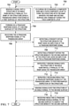
Figure 7 is an illustration of a flowchart of a method for inspecting a structure using ultrasonic techniques in accordance with an illustrative embodiment; -
Figure 8 is an illustration of a flowchart of a method for inspecting a structure using ultrasonic techniques in accordance with an illustrative embodiment; and -
Figure 9 is an illustration of a flowchart of a method for inspecting a structure using ultrasonic techniques in accordance with an illustrative embodiment. - The illustrative embodiments recognize and take into account one or more different considerations. For example, the illustrative embodiments recognize and take into account that inspecting porosity in composite structures that are steeply angled/ramped, for example having greater than thirty degrees, is undesirably difficult. The illustrative embodiments recognize and take into account that currently, ply ramp areas that change at a rate less than 20:1 are inspected. Ply ramp areas that change at a rate less than 20:1 change at a rate less than three degrees. The illustrative embodiments recognize and take into account that structures with steeper ramps may be desirable.
- The illustrative embodiments recognize and take into account that inspection requirements may need to be modified when a ramp in the structure has an angle greater than three degrees. The illustrative embodiments recognize and take into account that modifying inspection requirements may impact design of the structure. The illustrative embodiments recognize and take into account that increasing inconsistency detection near the ramp can enable improved design of structures.
- The illustrative embodiments recognize and take into account that conventional ultrasonic inspections send signals into a structure at an angle perpendicular to a backwall, or second surface, of the structure. The illustrative embodiments recognize and take into account that for many structures, the signals may be sent into the structure substantially perpendicular to the first surface. The illustrative embodiments recognize and take into account that when a second surface is ramped or angled relative to a first surface, the signals may be directed at an angle relative to the first surface into the structure in order to be perpendicular to the second surface.
- The illustrative embodiments recognize and take into account that for gently ramped areas (20:1), the process is to steer an ultrasonic beam perpendicular to the surface to be inspected. The illustrative embodiments recognize and take into account that for a steep angle, only a fraction of the sound path inspects the area of interest. Also, the illustrative embodiments recognize and take into account that steering the beam at steep angles is more difficult than desired.
- Referring now to the figures and, in particular, with reference to
Figure 1 , an illustration of a block diagram of an environment in which a composite structure is inspected using ultrasonic techniques in accordance with an illustrative embodiment. Ininspection environment 100,ultrasonic inspection equipment 102 inspectsstructure 104.Structure 104 hasramp 106 andsecond ramp 108.Ramp 106 hasfirst angle 110.First angle 110 is measured relative tofirst surface 112.First angle 110 is greater than three degrees. Theramp 106 forms anangle 110 between zero and thirty degrees with a line normal to thesecond surface 126. - In some illustrative examples,
first angle 110 is equal to or greater than sixty degrees. -
Second ramp 108 has second angle 114. Second angle 114 is measured relative tofirst surface 112. Second angle 114 is greater than three degrees. In some illustrative examples, second angle 114 is equal to or greater than sixty degrees. - In some illustrative examples,
structure 104 is formed ofcomposite material 115.Structure 104 is formed by co-curing or co-bondingcomposite skin 116 and thickcomposite layup 118. Plurality ofcomposite plies 120 are laid up to formcomposite skin 116. Second plurality ofcomposite plies 122 ofvarying widths 124 are laid up to formthick composite layup 118. -
Composite skin 116 and thickcomposite layup 118 are either co-cured or co-bonded to formstructure 104 withramp 106.Ramp 106 andsecond surface 126 are formed by curing thickcomposite layup 118. -
Ramp 106 is created byvarying widths 124 of second plurality ofcomposite plies 122.Second ramp 108 is created byvarying widths 124 of second plurality ofcomposite plies 122. - To inspect
structure 104 beneathramp 106,ultrasonic inspection equipment 102 sendssignals 130 intostructure 104 atangle 132.Angle 132 is substantially parallel tofirst angle 110. To inspect the whole ofstructure 104 beneathramp 106,angle 132 is desirably the same asfirst angle 110. However, some variations may occur in manufacturing ofstructure 104 or in operation ofultrasonic inspection equipment 102. As described herein, "substantially parallel" is within two degrees of another angle. Thus,angle 132 is within two degrees offirst angle 110. - In some illustrative examples,
ultrasonic inspection equipment 102 takes the form of transducer array 134. Transducer array 134 sendssignals 130, such assignal 136, intostructure 104 atangle 132 usingmechanical angle adjuster 138 orelectronic beam steering 140. Sendingsignals 130 and receiving ultrasound response signals 142 at transducer array 134 is referred to as "pulse echo inspection." - In some illustrative examples, ultrasound response signals 142 are formed at
second surface 126 and are received at transducer array 134. For example, whensignal 136 reachessecond surface 126,ultrasound response signal 144 is formed atsecond surface 126.Ultrasound response signal 144 hasangle 146.Angle 146 is a reflection ofangle 132 about a line normal tosecond surface 126. - The reception of ultrasound response signals 142 takes into
account angle 146. The reception of ultrasound response signals 142 is performed at an angle. This reception may be referred to as similar to "reverse" beam steering. The reception of ultrasound response signals is performed at a reflected angle toangle 132 either electronically or with a mechanical structure, such as a wedge. - After receiving
ultrasound response signal 144,porosity 148 withinstructure 104 underramp 106 is detected usingamplitude 150 ofultrasound response signal 144.Amplitude 150 ofultrasound response signal 144 is used to detect a porosity withinstructure 104 in the paths followed bysignal 136 andultrasound response signal 144. - By repeatedly sending
signals 130 intostructure 104 and repeatedly receiving ultrasound response signals 142,porosity 148 is detected for multiple locations beneathramp 106. In one illustrative example, by "stepping across"first surface 112,signals 130 are sent into different locations ofstructure 104 to detectporosity 148 for multiple locations beneathramp 106. In another illustrative example, by sendingsignals 130 intostructure 104 using different transmitters of phasedarray 162,signals 130 are sent into different locations ofstructure 104 to detectporosity 148 for multiple locations beneathramp 106. In some illustrative examples, signals 130 are sent into different locations ofstructure 104 using a combination of stepping transducer array 134 acrossfirst surface 112 and using different transmitters of phasedarray 162. - In some illustrative examples,
first angle 110 is a reflection of second angle 114. In these illustrative examples, signals 130 and ultrasound response signals 142 may be used to detectporosity 152 withinstructure 104 beneathsecond ramp 108. In these illustrative examples, althoughangle 132 is not parallel to second angle 114,angle 146 ofultrasound response signal 144 is parallel to second angle 114. - In other illustrative examples, signal 154 having
angle 156 substantially parallel to second angle 114 is sent intostructure 104 to detectporosity 152 withinstructure 104 beneathsecond ramp 108. In these illustrative examples, ultrasound response signal 158 forms atsecond surface 126.Amplitude 160 ofultrasound response signal 158 is used to detectporosity 152 withinstructure 104 beneathsecond ramp 108. - Ultrasound response signals 142 and
ultrasound response signal 158 may be received by a transducer array 134, such as phasedarray 162. In other illustrative examples, signals 130 are received byreceiver 164. - As depicted, signal 136 is sent into
structure 104, and signal 166 is received byreceiver 164. In these illustrative examples, signal 136 is sent intostructure 104 usingtransmitter 168.Amplitude 170 ofsignal 166 received byreceiver 164 may be used to detectporosity 148 withinstructure 104 beneathramp 106. Receivingsignal 166 atreceiver 164 may be referred to as "through transmission" ultrasonic inspection. - At least one of
signals 130 and signal 154 are sent intostructure 104 to inspectstructure 104 beneathramp 106 andsecond ramp 108. As used herein, the phrase "at least one of," when used with a list of items, means different combinations of one or more of the listed items may be used, and only one of each item in the list may be needed. In other words, "at least one of" means any combination of items and number of items may be used from the list, but not all of the items in the list are required. The item may be a particular object, a thing, or a category. - For example, "at least one of item A, item B, or item C" may include, without limitation, item A, item A and item B, or item B. This example also may include item A, item B, and item C, or item B and item C. Of course, any combination of these items may be present. In other examples, "at least one of" may be, for example, without limitation, two of item A, one of item B, and ten of item C; four of item B and seven of item C; or other suitable combinations.
- In some illustrative examples, at least one of
signals 130 or signal 154 are used to perform inspection sampling throughoutstructure 104. For example, signals 130 may be used to perform sampling throughoutstructure 104 including portions beneathsecond surface 126. - In some illustrative examples, signals 172 are sent into
structure 104 normal tosecond surface 126 in portions of structure that are not ramped. Ultrasound response signals 174 are received normal tosecond surface 126.Amplitude 176 of ultrasound response signals 174 is used to detectporosity 178 withinstructure 104 betweensecond surface 126 andfirst surface 112 ofstructure 104. - The illustration of
inspection environment 100 inFigure 1 is not meant to imply physical or architectural limitations to the manner in which an illustrative embodiment may be implemented. Other components in addition to or in place of the ones illustrated may be used. Some components may be unnecessary. Also, the blocks are presented to illustrate some functional components. One or more of these blocks may be combined, divided, or combined and divided into different blocks when implemented in an illustrative embodiment. - For example, at least one of
ramp 106 orsecond ramp 108 has significant variation in average surface roughness. Whenramp 106 has significant variation in surface roughness,ramp 106 may be referred to as having a rough surface. Whensecond ramp 108 has significant variation in surface roughness,second ramp 108 may be referred to as having a rough surface. - Further, although porosity is discussed,
ultrasonic inspection equipment 102 may be used to inspect for other types of inconsistencies. For example, signals 130 fromultrasonic inspection equipment 102 may be used to inspect for foreign object debris. When inspecting for foreign object debris, an associated time for ultrasound response signals 142 is used. - Turning now to
Figure 2 , an illustration of a cross-sectional view of a composite structure is depicted in accordance with an illustrative embodiment.Structure 200 is a physical implementation ofstructure 104 ofFigure 1 . -
Structure 200 hasfirst surface 202 andsecond surface 204.Second surface 204 is parallel tofirst surface 202. Signals sent intofirst surface 202 travel indirection 206 and ultrasound response signals are reflected off ofsecond surface 204. Ultrasonic inspection using signals normal tofirst surface 202 may be performed inregion 208 ofstructure 200.First surface 202 is substantially planar. As depicted,second surface 204 is also substantially planar. -
Structure 200 includesramp 210 andramp 212.Ramp 210 hasrough surface 214.Angle 216 oframp 210 relative tosecond surface 204 is greater than sixty degrees. An angle oframp 210 relative to a line normal tosecond surface 204 is thirty degrees or less. Due torough surface 214 andangle 216, traditional ultrasonic inspection is not performed onstructure 200 beneathramp 210. -
Ramp 212 hasrough surface 218.Angle 220 oframp 212 relative tosecond surface 204 is greater than sixty degrees. An angle oframp 212 relative to a line normal tosecond surface 204 is thirty degrees or less. Due torough surface 218 andangle 220, traditional ultrasonic inspection is not performed onstructure 200 beneathramp 212. - The illustration of
structure 200 inFigure 2 is not meant to imply physical or architectural limitations to the manner in which an illustrative embodiment may be implemented. For example,ramp 210 and ramp 212 may have any desirable angle relative tofirst surface 202. For inspection using angled ultrasonic signals,ramp 210 and ramp 212 are each sixty degrees or more fromfirst surface 202. Whenramp 210 is sixty degrees or more fromfirst surface 202,ramp 210 and a directed ultrasonic signal to inspectstructure 200 belowramp 210 are each thirty degrees or less from a line normal tofirst surface 202. - Turning now to
Figure 3 , an illustration of a cross-sectional view of an ultrasonic inspection of a ramp of a composite structure is depicted in accordance with an illustrative embodiment. View 300 is an illustration of an ultrasonic inspection ofstructure 200 ofFigure 2 . Inview 300,transducer array 302 sends signal 304 intofirst surface 202 ofstructure 200.Signal 304 is sent intostructure 200 atangle 306 substantially parallel to ramp 210 ofstructure 200 usingtransducer array 302. As depicted, signal 304 is sent intostructure 200 atangle 306 using electronic beam steering. -
Transducer array 302 is a physical implementation of transducer array 134.Figure 3 depicts a "pulse echo inspection."Transducer array 302 both sends signals, such assignal 304, and receives ultrasound response signals, such asultrasound response signal 308. - As can be seen in
Figure 3 ,coupling material 313couples transducer array 302 to structure 200.Coupling material 313 takes the form of water or any other desirable coupling material.Transducer array 302 sends signal 316 intocoupling material 313. When signal 316 reaches surface 202 ofstructure 200, signal 316 refracts to causesignal 304 to enterstructure 200 atangle 306.Angle 306 is a refraction angle.Angle 306 is related to the array steering angle forsignal 316 by Snell's law. In some illustrative examples, the velocity ofcoupling material 313 is approximately half the velocity ofstructure 200. In these illustrative examples,angle 306 is roughly twice the array steering angle ofsignal 316. -
Ultrasound response signal 308 is formed atsecond surface 204 ofstructure 200. In some illustrative examples, for ultrasonic inspections,second surface 204 may be referred to asback wall 310.Ultrasound response signal 308 is received attransducer array 302.Ultrasound response signal 308 hasangle 312 relative tofirst surface 202.Angle 312 is a reflection ofangle 306 aboutline 314 normal tofirst surface 202. - Ramp 210 forms an angle between zero and thirty degrees with
line 314 normal tosecond surface 204. Ramp 212 forms an angle between zero and thirty degrees withline 314 normal tosecond surface 204. - As depicted,
angle 306 andangle 312 are each greater than sixty degrees.Angle 306 andangle 312 are desirably greater than sixty degrees so that each ofsignal 304 andultrasound response signal 308 are no more than thirty degrees relative toline 314 normal tofirst surface 202. - As depicted, when
ultrasound response signal 308 reaches surface 202 ofstructure 200,ultrasound response signal 308 is refracted to formresponse signal 318.Transducer array 302 receivesultrasound response signal 308 in the form of response signal 318 fromcoupling material 313. - A porosity within
structure 200 beneathramp 210 can be detected from the amplitude ofultrasound response signal 308. The porosity withinstructure 200 alongsignal 304 may be detected usingultrasound response signal 308. - In some illustrative examples, to detect porosity using
ultrasound response signal 308, porosity alongsignal 304 and porosity alongultrasound response signal 308 are assumed to be equal. In these illustrative examples, an average porosity alongsignal 304 and alongultrasound response signal 308 is evaluated from the signal strength. The signal strength in the presence of porosity would decrease when compared to a porosity free zone. - In some illustrative examples, porosity along
ultrasound response signal 308 is known from previous inspections. In these illustrative examples, porosity alongsignal 304 is detected usingultrasound response signal 308 and the known porosity from previous inspections. -
Ultrasound response signal 308 travels throughstructure 200 beneathsecond surface 204. A porosity withinstructure 200 along the path ofultrasound response signal 308 may be detected usingultrasound response signal 308. - Turning now to
Figure 4 , an illustration of a cross-sectional view of an ultrasonic inspection of a ramp of a composite structure is depicted in accordance with an illustrative embodiment. View 400 is an illustration of an ultrasonic inspection ofstructure 200 ofFigure 2 . Inview 400,transmitter 402 sends signal 404 intofirst surface 202 ofstructure 200.Signal 404 is sent intostructure 200 atangle 406 substantially parallel to ramp 210 ofstructure 200 usingtransmitter 402. As depicted, signal 404 is sent intostructure 200 atangle 406 using electronic beam steering. In other non-depicted examples, signal 404 may be sent intostructure 200 using a mechanical angle adjuster.Transmitter 402 is coupled to structure 200 usingwater 407 or other desirable coupling material. -
Receiver 408 is positioned atsecond surface 204 ofstructure 200.Receiver 408 receives signal 404 atangle 406. An amplitude ofsignal 404 is used to detect a porosity withinstructure 200 beneathramp 210. Porosity withinstructure 200 alongsignal 404 can be detected from the amplitude ofsignal 404.Receiver 408 is coupled to structure 200 usingwater 409 or other desirable coupling material. - Turning now to
Figure 5 , an illustration of a cross-sectional view of an ultrasonic inspection of a ramp of a composite structure is depicted in accordance with an illustrative embodiment. Inview 500,transducer array 302 has moved indirection 502 relative to structure 200. - After receiving
ultrasound response signal 308 inFigure 3 ,transducer array 302 sends another signal intostructure 200 atangle 306 to detect a porosity within another portion ofstructure 200 beneathramp 210. Inview 500,transducer array 302 has moved indirection 502 after receivingultrasound response signal 308 inFigure 3 . - In
view 500,transducer array 302 sends signal 504 intostructure 200 atangle 306.Angle 306 is substantially parallel to ramp 210 ofstructure 200. As depicted, signal 504 is sent intostructure 200 atangle 306 using electronic beam steering. -
Ultrasound response signal 506 is formed atsecond surface 204 ofstructure 200.Ultrasound response signal 506 is received attransducer array 302.Ultrasound response signal 506 hasangle 312 relative tofirst surface 202.Angle 312 is a reflection ofangle 306. - A porosity within
structure 200 beneathramp 210 can be detected from the amplitude ofultrasound response signal 506. The porosity withinstructure 200 alongsignal 504 may be detected usingultrasound response signal 506. In some illustrative examples, to detect porosity usingultrasound response signal 506, porosity alongsignal 504 and porosity alongultrasound response signal 506 are assumed to be equal. In these illustrative examples, an average porosity alongsignal 504 and alongultrasound response signal 506 is evaluated from the signal strength. The signal strength in the presence of porosity would decrease when compared to a porosity free zone. - In some illustrative examples, porosity along
ultrasound response signal 506 is known from previous inspections. In these illustrative examples, porosity alongsignal 504 is detected usingultrasound response signal 506 and the known porosity from previous inspections. -
Ultrasound response signal 506 travels throughstructure 200 beneathsecond surface 204. A porosity withinstructure 200 along the path ofultrasound response signal 506 may be detected usingultrasound response signal 506. - In this illustrative example,
transducer array 302 may be moved indirection 502 prior to sending another signal intostructure 200. In another illustrative example, a different transmitting cell oftransducer array 302 sends a signal intostructure 200. In this illustrative example, a transmitting cell indirection 502 from transmittingcell 508 sends another signal instructure 200. By using a different transmitting cell or movingtransducer array 302, signals may be introduced in a pulsed fashion across the area beneathramp 210. - Turning now to
Figure 6 , an illustration of a cross-sectional view of an ultrasonic inspection of a ramp of a composite structure is depicted in accordance with an illustrative embodiment. Inview 600,transducer array 302 has moved indirection 502 relative to structure 200. - In
view 600,transducer array 302 sends signal 602 intostructure 200 atangle 306.Angle 306 is substantially parallel to ramp 210 ofstructure 200.Ramp 210 is a reflection oframp 212 about a line normal tofirst surface 202. The absolute values ofangle 216 andangle 220 are substantially the same. Accordingly, signals with substantially the same angle,angle 306 could be sent intostructure 200 to detect porosity under bothramp 210 andramp 212. - As depicted,
angle 306 is a reflection oframp 212. As depicted, signal 602 is sent intostructure 200 atangle 306 using electronic beam steering. -
Ultrasound response signal 604 is formed atsecond surface 204 ofstructure 200.Ultrasound response signal 604 is received attransducer array 302.Ultrasound response signal 604 hasangle 312 relative tofirst surface 202.Angle 312 is a reflection ofangle 306.Angle 312 ofultrasound response signal 604 is substantially parallel to ramp 212 ofstructure 200. - A porosity within
structure 200 beneathramp 212 can be detected from the amplitude ofultrasound response signal 604.Ultrasound response signal 604 travels beneathramp 212. The porosity withinstructure 200 alongultrasound response signal 604 may be detected usingultrasound response signal 604. -
Signal 602 travels throughstructure 200 beneathsecond surface 204. A porosity withinstructure 200 along the path ofsignal 602 may be detected usingultrasound response signal 604. - In other non-depicted examples,
transducer array 302 sends asignal having angle 312 relative tofirst surface 202 intostructure 200. In these non-depicted examples, an ultrasound responsesignal having angle 306 is received attransducer array 302. In these non-depicted examples, signals parallel to ramp 212, also referred to as a second ramp, are used to detect porosity belowramp 212. In some illustrative examples,signals having angle 312 are used whenramp 212 and ramp 210 are not reflections of each other. For example, signals sent intostructure 200 havingangle 312 may be used to detect porosity beneathramp 212 whenangle 216 andangle 220 do not have the same absolute value. - In yet other non-depicted illustrative examples,
transducer array 302 sends a signal having an angle that is a reflection oframp 212 intostructure 200 to detect porosity withinstructure 200 beneathramp 212, in which the angle is different from the angle of signals used to inspectramp 210. For example, whenangle angle 312. - The different components shown in
Figures 2-6 may be combined with components inFigure 1 , used with components inFigure 1 , or a combination of the two. Additionally, some of the components inFigures 2-6 may be illustrative examples of how components shown in block form inFigure 1 can be implemented as physical structures. - Turning now to
Figure 7 , an illustration of a flowchart of a method for inspecting a structure using ultrasonic techniques is depicted in accordance with an illustrative embodiment.Method 700 may be implemented ininspection environment 100 ofFigure 1 .Method 700 may be implemented onstructure 200 ofFigures 2-6 . -
Method 700 sends a signal into a structure at an angle substantially parallel to a ramp of the structure using a transducer array positioned at a first surface of the structure (operation 702). In some illustrative examples, the structure comprises a composite material. In some illustrative examples, the ramp forms an angle between zero and thirty degrees with a line normal to the second surface. In some illustrative examples, the ramp has significant surface variation in average surface roughness. - Method forms an ultrasound response signal at a second surface of the structure (operation 704).
Method 700 receives the ultrasound response signal at the transducer array operation 706). - In some illustrative examples,
method 700 detects a porosity within the structure beneath the ramp using an amplitude of the ultrasound response signal (operation 708). In some illustrative examples,method 700 detects a porosity within the structure beneath the second surface of the structure using an amplitude of the ultrasound response signal (operation 710). - In some illustrative examples,
method 700 repeatedly sends signals into the structure at an angle substantially parallel to the ramp using the transducer array (operation 712). In these illustrative examples,method 700 repeatedly receives resulting ultrasound response signals at the transducer array to perform sampled inspection of the structure (operation 714). - In some illustrative examples,
method 700 also sends signals into the structure at an angle normal to the second surface (operation 716). In these illustrative examples,method 700 receives resulting ultrasound response signals normal to the second surface to inspect the structure beneath the second surface (operation 718). - The structure may optionally be formed as part of
method 700. In some illustrative examples,method 700 co-cures or co-bonds a composite skin and a thick composite layup to form the structure with the ramp, wherein the ramp and second surface are formed by curing the thick composite layup (operation 720). The composite skin and the thick composite layup may be formed in any desirable fashion. In some illustrative examples, a plurality of composite plies is laid up to form a composite skin. In some illustrative examples, a second plurality of composite plies of varying widths are laid up to form a thick composite layup. - As depicted,
operations 708 through 720 are optional.Operations 708 through 720 may occur in some illustrative examples and be absent in others. - Turning now to
Figure 8 , an illustration of a flowchart of a method for inspecting a structure using ultrasonic techniques is depicted in accordance with an illustrative embodiment.Method 800 may be implemented ininspection environment 100 ofFigure 1 .Method 800 may be implemented onstructure 200 ofFigures 2-6 . -
Method 800 sends a signal into a structure at an angle substantially parallel to a ramp of the structure using a transmitter positioned at a first surface of the structure (operation 802). Sending the signal into the structure at the angle comprises steering a beam using one of a mechanical angle adjuster or electronic beam steering. In some illustrative examples, the structure comprises a composite material. In some illustrative examples, the ramp forms an angle between zero and thirty degrees with a line normal to the second surface. -
Method 800 receives the signal at a second surface of the structure using a receiver to form a received signal, wherein the transmitter is separate from the receiver (operation 804).Method 800 identifies an inconsistency in the structure using the received signal (operation 806). - In some illustrative examples,
method 800 detects a porosity within a portion the structure beneath the ramp using an amplitude of the received signal (operation 808). In some illustrative examples,method 800 repeatedly sends signals into the structure at the angle substantially parallel to the ramp using the transmitter (operation 810). In some illustrative examples,method 800 repeatedly receives the signals at the receiver to inspect the structure beneath the ramp (operation 812) . - In some illustrative examples,
method 800 sends signals into the structure at an angle normal to the second surface (operation 814). In some illustrative examples,method 800 receives resulting ultrasound response signals normal to the second surface to inspect the structure beneath the second surface (operation 816). - In some illustrative examples,
method 800 sends a second signal into the structure at an angle substantially parallel to a second ramp of the structure using the transmitter (operation 818). In some illustrative examples,method 800 receives the second signal at the second surface of the structure using a receiver to form a second received signal (operation 820). In some illustrative examples,method 800 detects a porosity within a portion the structure beneath the second ramp using an amplitude of the second received signal (operation 822). - As depicted,
operations 808 through 822 are optional.Operations 808 through 822 may occur in some illustrative examples and be absent in others. - Turning now to
Figure 9 , an illustration of a flowchart of a method for inspecting a structure using ultrasonic techniques is depicted in accordance with an illustrative embodiment.Method 900 may be implemented ininspection environment 100 ofFigure 1 .Method 900 may be implemented onstructure 200 ofFigures 2-6 . -
Method 900 sends a signal into a structure at a first angle in which the first angle is a reflection of a second angle of a second ramp of the structure, in which the signal is sent into the structure using a transducer array positioned at a first surface of the structure (operation 902). In some illustrative examples, the second ramp forms an angle between zero and thirty degrees with a line normal to the second surface.Method 900 forms an ultrasound response signal at a second surface of the structure (operation 904). -
Method 900 receives an ultrasound response signal at the transducer array (operation 906).Method 900 detects a porosity within a portion of the structure beneath the second ramp using the amplitude of the ultrasound response signal (operation 908). Afterwards the method terminates. - In some illustrative examples,
method 900 sends signals into the structure at an angle normal to the second surface (operation 910). In these illustrative examples,method 900 receives resulting ultrasound response signals normal to the second surface to inspect the structure beneath the second surface (operation 912). - While the scope of protection is determined by the appended claims, realizations of the present disclosure can be made in many ways including, but not limited to, those according to the following Clauses:
- A1. A method comprising: sending (702) a signal (136) into a structure (104) at an angle (132) substantially parallel to a ramp (106) of the structure (104) using a transducer array (134) positioned at a first surface (112) of the structure (104); forming (704) an ultrasound response signal (144) at a second surface (126) of the structure (104); and receiving (706) the ultrasound response signal (144) at the transducer array (134). A2. The method of A1 further comprising: repeatedly sending (712) signals (130) into the structure (104) at an angle (132) substantially parallel to the ramp (106) using the transducer array (134); and repeatedly receiving (714) resulting ultrasound response signals (142) at the transducer array (134) to perform sampled inspection of the structure (104).
- A3. The method of A1 or A2 further comprising: detecting (708) a porosity (148) within the structure (104) beneath the ramp (106) using an amplitude (150) of the ultrasound response signal (144).
- A4. The method of A1 or A2 further comprising: detecting (710) a porosity (178) within the structure (104) beneath the second surface (126) of the structure (104) using an amplitude (150) of the ultrasound response signal (144).
- A5. The method of any one of A1 to A4 further comprising: sending (716) signals (172) into the structure (104) at an angle normal to the second surface (126); and receiving (718) resulting ultrasound response signals (174) normal to the second surface (126) to inspect the structure (104) beneath the second surface (126).
- A6. The method of any one of A1 to A5 wherein the structure (104) comprises a composite material (115).
- A7. The method of A6 further comprising: co-curing or co-bonding (720) a composite skin (116) and a thick composite layup (118) to form the structure (104) with the ramp (106), wherein the ramp (106) and second surface (126) are formed by curing the thick composite layup (118).
- A8. The method of any one of A1 to A8, wherein the ramp (106) forms an angle (110) between zero and thirty degrees with a line normal to the second surface (126).
- B1. A method comprising: sending (802) a signal (136) into a structure (104) at an angle (132) substantially parallel to a ramp (106) of the structure (104) using a transmitter (168) positioned at a first surface (112) of the structure (104); receiving (804) the signal (136) at a second surface (126) of the structure (104) using a receiver (164) to form a received signal (166), wherein the transmitter (168) is separate from the receiver (164); and identifying (806) an inconsistency in the structure (104) using the received signal (136).
- B2. The method of B1 further comprising: detecting (808) a porosity (148) within a portion the structure (104) beneath the ramp (106) using an amplitude (170) of the received signal (136) .
- B3. The method of B1 or B2, wherein the ramp (106) forms an angle (132) between zero and thirty degrees with a line normal to the second surface (126).
- B4. The method of B1, B2 or B3, wherein sending the signal (136) into the structure (104) at the angle (132) comprises steering a beam using one of a mechanical angle adjuster (138) or electronic beam steering (140).
- B5. The method of any one of B1 to B4 further comprising: repeatedly sending (810) signals (130) into the structure (104) at the angle (132) substantially parallel to the ramp (106) using the transmitter (168); and repeatedly receiving (812) the signals (130) at the receiver (164) to inspect the structure (104) beneath the ramp (106).
- B6. The method of any one of B1 to B5 further comprising: sending (814) signals (172) into the structure (104) at an angle normal to the second surface (126); and receiving (816) resulting ultrasound response signals (142) normal to the second surface (126) to inspect the structure (104) beneath the second surface (126).
- B7. The method of any one of B1 to B6 further comprising: sending (818) a second signal (154) into the structure (104) at an angle (156) substantially parallel to a second ramp (108) of the structure (104) using the transmitter (168); receiving (820) the second signal (154) at the second surface (126) of the structure (104) using a receiver (164) to form a second received signal; and detecting (822) a porosity (152) within a portion of the structure (104) beneath the second ramp (108) using an amplitude of the second received signal.
- B8. The method of B1, wherein signal (404) is sent into structure (200) at an angle (406) using electronic beam steering.
- B9. The method of B1, wherein signal (404) is sent into structure (200) at an angle (406) using a mechanical angle adjuster.
- B10. The method of B1, wherein the transmitter (402) and the receiver (408) are coupled to structure (200) using water (407, 409) or other deisderable coupling material.
- B11. The method of any one of B1 to B10 wherein the structure (104) comprises a composite material (115).
- C1. A method comprising: sending (902) a signal (602) into a structure (200) at a first angle (306) in which the first angle (306) is a reflection of a second angle (220) of a second ramp (212, 108) of the structure (200), in which the signal (602) is sent into the structure (200) using a transducer array (302) positioned at a first surface (202) of the structure (200); forming (904) an ultrasound response signal (604) at a second surface (204) of the structure (200); receiving (906) the ultrasound response signal (604) at the transducer array (302); and detecting (908) a porosity (152) within a portion of the structure (200) beneath the second ramp (212, 108) using an amplitude of the ultrasound response signal (604).
- C2. The method of C1, wherein the second ramp (212, 108) forms an angle (114) between zero and thirty degrees with a line normal to the second surface (204, 126).
- C3. The method of C1 or C2 further comprising: sending (910) signals (172) into the structure (200, 104) at an angle normal to the second surface (204, 126); and receiving (912) resulting ultrasound response signals (174) normal to the second surface (204, 126) to inspect the structure (200, 104) beneath the second surface (204, 126).
- C4. The method of C1, C2, or C3, wherein the structure (200) comprises a composite material.
- The flowcharts and block diagrams in the different depicted embodiments illustrate the architecture, functionality, and operation of some possible implementations of apparatus and methods in an illustrative embodiment. In this regard, each block in the flowcharts or block diagrams may represent a module, a segment, a function, and/or a portion of an operation or step.
- In some alternative implementations of an illustrative embodiment, the function or functions noted in the blocks may occur out of the order noted in the figures. For example, in some cases, two blocks shown in succession may be executed substantially concurrently, or the blocks may sometimes be performed in the reverse order, depending upon the functionality involved. Also, other blocks may be added, in addition to the illustrated blocks, in a flowchart or block diagram.
- The illustrative examples provide methods in which an ultrasound beam is steered parallel to the ramp that is being inspected rather than perpendicular to the surface. The illustrative examples could be performed in pitch catch or through transmission. The illustrative examples direct the sending signal up to and adjacent to the ramp surface. The illustrative examples provide desirable sensitivity to inconsistencies in the ramp.
- In some illustrative examples, inspections using beam steering parallel to a ramp are combined with inspection using traditional non-beam steering path. By combining the beam steering with normal signals in traditional ultrasonic inspections, a desirable coverage of composite structure is obtained. In these illustrative examples, the traditional normal ultrasonic paths are used to inspect for inconsistencies that are parallel to the top of the part surface. Further, traditional normal ultrasonic paths may be used to inspect for inconsistencies, such as wrinkles, beneath a parallel back surface.
- The description of the different illustrative embodiments has been presented for purposes of illustration and description and is not intended to be exhaustive or limited to the embodiments in the form disclosed. Many modifications and variations will be apparent to those of ordinary skill in the art in accordance with the appended claims.
Claims (15)
- A method for inspecting porosity or foreign debris in a structure having a ramp (106, 210) comprising:sending (802) a signal (136, 404) into a structure (104, 200) at an angle (132, 406) substantially parallel to the ramp (106, 210) of the structure (104, 200) using a transmitter (168, 402) positioned at a first surface (112, 202) of the structure (104, 200);receiving (804) the signal (136, 404) at a second surface (126, 204) of the structure (104, 200) using a receiver (164, 408) to form a received signal (166), wherein the transmitter (168, 402) is separate from the receiver (164, 408); and identifying (806) an inconsistency in the structure (104, 200) using the received signal (136).
- The method of claim 1 further comprising:
detecting (808) a porosity (148) within a portion of the structure (104, 200) beneath the ramp (106, 210) using an amplitude (170) of the received signal (136). - The method of claim 1 or 2 wherein the ramp (106) forms an angle (132) between zero and thirty degrees with a line normal to the second surface (126).
- The method of any one of claims 1 to 3 wherein sending the signal (136) into the structure (104) at the angle (132) comprises steering a beam using one of a mechanical angle adjuster (138) or electronic beam steering (140).
- The method of any one of claims 1 to 4 further comprising:
repeatedly sending (810) signals (130) into the structure (104) at the angle (132) substantially parallel to the ramp (106) using the transmitter (168). - The method of any one of claims 1 to 5 further comprising:
repeatedly receiving (812) the signals (130) at the receiver (164) to inspect the structure (104) beneath the ramp (106). - The method of any one of claims 1 to 6 further comprising:
sending (814) signals (172) into the structure (104) at an angle normal to the second surface (126). - The method of any one of claims 1 to 7 further comprising:
receiving (816) resulting ultrasound response signals (142) normal to the second surface (126) to inspect the structure (104) beneath the second surface (126). - The method of any one of claims 1 to 8 further comprising:
sending (818) a second signal (154) into the structure (104) at an angle (156) substantially parallel to a second ramp (108) of the structure (104) using the transmitter (168). - The method of claim 9 further comprising:
receiving (820) the second signal (154) at the second surface (126) of the structure (104) using a receiver (164) to form a second received signal. - The method of claim 10 further comprising:
detecting (822) a porosity (152) within a portion of the structure (104) beneath the second ramp (108) using an amplitude of the second received signal. - The method of claim 1, wherein signal (404) is sent into structure (200) at an angle (406) using electronic beam steering.
- The method of claim 1, wherein signal (404) is sent into structure (200) at an angle (406) using a mechanical angle adjuster.
- The method of claim 1, wherein the transmitter (402) and the receiver (408) are coupled to structure (200) using water (407, 409) or other deisderable coupling material.
- The method of any one of claims 1 to 14 wherein the structure (104) comprises a composite material (115).
Applications Claiming Priority (2)
| Application Number | Priority Date | Filing Date | Title |
|---|---|---|---|
| US15/821,665 US10571385B2 (en) | 2017-11-22 | 2017-11-22 | Ultrasonic inspection of a structure with a ramp |
| EP18194165.9A EP3489674B1 (en) | 2017-11-22 | 2018-09-13 | Ultrasonic inspection of a structure with a ramp |
Related Parent Applications (2)
| Application Number | Title | Priority Date | Filing Date |
|---|---|---|---|
| EP18194165.9A Division-Into EP3489674B1 (en) | 2017-11-22 | 2018-09-13 | Ultrasonic inspection of a structure with a ramp |
| EP18194165.9A Division EP3489674B1 (en) | 2017-11-22 | 2018-09-13 | Ultrasonic inspection of a structure with a ramp |
Publications (1)
| Publication Number | Publication Date |
|---|---|
| EP3961205A1 true EP3961205A1 (en) | 2022-03-02 |
Family
ID=63579133
Family Applications (2)
| Application Number | Title | Priority Date | Filing Date |
|---|---|---|---|
| EP18194165.9A Active EP3489674B1 (en) | 2017-11-22 | 2018-09-13 | Ultrasonic inspection of a structure with a ramp |
| EP21196138.8A Withdrawn EP3961205A1 (en) | 2017-11-22 | 2018-09-13 | Method for inspecting porosity or foreign debris in a structure |
Family Applications Before (1)
| Application Number | Title | Priority Date | Filing Date |
|---|---|---|---|
| EP18194165.9A Active EP3489674B1 (en) | 2017-11-22 | 2018-09-13 | Ultrasonic inspection of a structure with a ramp |
Country Status (6)
| Country | Link |
|---|---|
| US (1) | US10571385B2 (en) |
| EP (2) | EP3489674B1 (en) |
| JP (1) | JP7156912B2 (en) |
| CN (1) | CN109805956B (en) |
| ES (1) | ES2901473T3 (en) |
| PT (1) | PT3489674T (en) |
Families Citing this family (5)
| Publication number | Priority date | Publication date | Assignee | Title |
|---|---|---|---|---|
| US10816512B2 (en) * | 2018-03-29 | 2020-10-27 | The Boeing Company | Inspection of a structure with a sloped back wall |
| US10816510B1 (en) * | 2019-04-20 | 2020-10-27 | The Boeing Company | System and method for using eddy current edge effect to measure a gap between two conductive parts |
| US11435323B2 (en) | 2019-12-17 | 2022-09-06 | The Boeing Company | Method and system for automated ultrasonic inspection of complex composite structures with non-parallel surfaces |
| US11561078B2 (en) * | 2020-04-03 | 2023-01-24 | The Boeing Company | Methods and systems for measuring gaps between exterior structures and interior structures |
| US11644444B2 (en) | 2021-02-23 | 2023-05-09 | The Boeing Company | Ultrasonic inspection margin check for design and manufacturing |
Citations (5)
| Publication number | Priority date | Publication date | Assignee | Title |
|---|---|---|---|---|
| GB2013344A (en) * | 1977-10-28 | 1979-08-08 | Balteau Sonatest Ltd | Ultrasonic flaw detection |
| US20020088282A1 (en) * | 2000-12-07 | 2002-07-11 | Zayicek Paul A. | Inspection of shrunk-on steam turbine disks using advanced ultrasonic techniques |
| EP1348953A2 (en) * | 2002-03-28 | 2003-10-01 | ROLLS-ROYCE plc | A method of ultrasonically detecting a change in the structure of a complex shape article |
| EP2031385A1 (en) * | 2006-06-13 | 2009-03-04 | Sumitomo Metal Industries Limited | Ultrasonic flaw detecting method, manufacturing method for welded steel pipe, and ultrasonic flaw detecting apparatus |
| JP2011163814A (en) * | 2010-02-05 | 2011-08-25 | Mitsubishi Heavy Ind Ltd | Ultrasonic flaw detection testing method |
Family Cites Families (15)
| Publication number | Priority date | Publication date | Assignee | Title |
|---|---|---|---|---|
| US4502331A (en) * | 1983-09-14 | 1985-03-05 | Southwest Research Institute | Method for ultrasonic inspection of turbine disc rims |
| US4803639A (en) * | 1986-02-25 | 1989-02-07 | General Electric Company | X-ray inspection system |
| JPH0618488A (en) * | 1992-07-06 | 1994-01-25 | Mitsubishi Heavy Ind Ltd | Ultrasonic inspecting method for composite material |
| JPH08184582A (en) * | 1994-12-27 | 1996-07-16 | Hitachi Constr Mach Co Ltd | Ultrasonic array probe for bevel flaw detection |
| WO2006103183A1 (en) * | 2005-03-31 | 2006-10-05 | Siemens Aktiengesellschaft | Acoustic test method for a test object and corresponding system for carrying out said method |
| US7617715B2 (en) | 2006-12-21 | 2009-11-17 | The Boeing Company | Reference standard for ultrasonic measurement of porosity and related method |
| JP2008216125A (en) | 2007-03-06 | 2008-09-18 | Mitsubishi Electric Corp | Ultrasonic probe |
| US7654143B2 (en) * | 2007-04-03 | 2010-02-02 | General Electric Company | Method and apparatus for in-situ inspection of rotary machine components |
| JP5535680B2 (en) | 2010-02-22 | 2014-07-02 | 三菱重工業株式会社 | Ultrasonic inspection method |
| US8874384B1 (en) * | 2010-09-14 | 2014-10-28 | The Boeing Company | Method and devices to standardize ultrasonic porosity measurements |
| CN102426194A (en) * | 2011-11-15 | 2012-04-25 | 北京理工大学 | Array ultrasonic detection technology of complex surface microdefect |
| US9176099B2 (en) | 2012-05-08 | 2015-11-03 | The Boeing Company | Variable radius inspection using sweeping linear array |
| US9500627B2 (en) | 2012-06-26 | 2016-11-22 | The Boeing Company | Method for ultrasonic inspection of irregular and variable shapes |
| US9304114B2 (en) | 2013-04-11 | 2016-04-05 | The Boeing Company | Ultrasonic inspection using incidence angles |
| JP6161161B2 (en) | 2013-12-25 | 2017-07-12 | 国立大学法人京都大学 | Porosity evaluation method and porosity evaluation apparatus in composite material |
-
2017
- 2017-11-22 US US15/821,665 patent/US10571385B2/en active Active
-
2018
- 2018-09-13 EP EP18194165.9A patent/EP3489674B1/en active Active
- 2018-09-13 EP EP21196138.8A patent/EP3961205A1/en not_active Withdrawn
- 2018-09-13 PT PT181941659T patent/PT3489674T/en unknown
- 2018-09-13 ES ES18194165T patent/ES2901473T3/en active Active
- 2018-09-18 CN CN201811086654.5A patent/CN109805956B/en active Active
- 2018-11-07 JP JP2018209674A patent/JP7156912B2/en active Active
Patent Citations (5)
| Publication number | Priority date | Publication date | Assignee | Title |
|---|---|---|---|---|
| GB2013344A (en) * | 1977-10-28 | 1979-08-08 | Balteau Sonatest Ltd | Ultrasonic flaw detection |
| US20020088282A1 (en) * | 2000-12-07 | 2002-07-11 | Zayicek Paul A. | Inspection of shrunk-on steam turbine disks using advanced ultrasonic techniques |
| EP1348953A2 (en) * | 2002-03-28 | 2003-10-01 | ROLLS-ROYCE plc | A method of ultrasonically detecting a change in the structure of a complex shape article |
| EP2031385A1 (en) * | 2006-06-13 | 2009-03-04 | Sumitomo Metal Industries Limited | Ultrasonic flaw detecting method, manufacturing method for welded steel pipe, and ultrasonic flaw detecting apparatus |
| JP2011163814A (en) * | 2010-02-05 | 2011-08-25 | Mitsubishi Heavy Ind Ltd | Ultrasonic flaw detection testing method |
Also Published As
| Publication number | Publication date |
|---|---|
| EP3489674A1 (en) | 2019-05-29 |
| CN109805956B (en) | 2023-05-23 |
| JP2019095438A (en) | 2019-06-20 |
| EP3489674B1 (en) | 2021-11-03 |
| ES2901473T3 (en) | 2022-03-22 |
| PT3489674T (en) | 2022-01-20 |
| US20190154561A1 (en) | 2019-05-23 |
| JP7156912B2 (en) | 2022-10-19 |
| CN109805956A (en) | 2019-05-28 |
| US10571385B2 (en) | 2020-02-25 |
Similar Documents
| Publication | Publication Date | Title |
|---|---|---|
| EP3961205A1 (en) | Method for inspecting porosity or foreign debris in a structure | |
| US7458266B2 (en) | Method and apparatus for detecting a load change upon a structure and analyzing characteristics of resulting damage | |
| CA1241106A (en) | Ultrasonic wheel probe with acoustic barrier | |
| Tan et al. | Comparison of Lamb waves and pulse echo in detection of near-surface defects in laminate plates | |
| US8286488B2 (en) | Apparatus and system for measuring material thickness | |
| JP2013507640A (en) | System and method for detecting and measuring interface properties of single-layer and multi-layer objects | |
| US10677715B2 (en) | Thermography inspection for near-surface inconsistencies of composite structures | |
| US7938007B2 (en) | Method for inspecting joined material interfaces | |
| EP2273259B1 (en) | Method and apparatus for detecting flaws in a railhead | |
| US8739630B2 (en) | Pulse-echo method for determining the damping block geometry | |
| US20090032329A1 (en) | Imaging an anomaly using backscattered waves | |
| EP3767288B1 (en) | Joint inspection system and methods of inspecting a joint in a structure | |
| CN102323334A (en) | Energy factor based ultrasonic guided wave detection method of debonding defect of bonding structure | |
| CN111189914B (en) | Method for determining gradient thickness coefficient for ultrasonic detection of composite material | |
| EP2984479B1 (en) | Ultrasonic inspection using incidence angles | |
| US10816512B2 (en) | Inspection of a structure with a sloped back wall | |
| US20070095140A1 (en) | Single-side ultrasonic inspection systems and methods | |
| EP2861977A1 (en) | Non-destructive ultrasound testing of structures made of composite material | |
| US11333632B2 (en) | Apparatus and a method for ultrasonic inspection of multi-layered structures | |
| JPS63263467A (en) | Ultrasonic flaw detecting method | |
| JP3590213B2 (en) | Ultrasonic inspection method and ultrasonic inspection apparatus | |
| US20250389612A1 (en) | Composite joint inspection | |
| JPH0550706B2 (en) | ||
| CN109187741A (en) | Large-scale storage tank bottom plate weld seam health status on-line monitoring method | |
| CA1067614A (en) | Pulse-echo method and system for testing wall thicknesses |
Legal Events
| Date | Code | Title | Description |
|---|---|---|---|
| PUAI | Public reference made under article 153(3) epc to a published international application that has entered the european phase |
Free format text: ORIGINAL CODE: 0009012 |
|
| STAA | Information on the status of an ep patent application or granted ep patent |
Free format text: STATUS: THE APPLICATION HAS BEEN PUBLISHED |
|
| AC | Divisional application: reference to earlier application |
Ref document number: 3489674 Country of ref document: EP Kind code of ref document: P |
|
| AK | Designated contracting states |
Kind code of ref document: A1 Designated state(s): AL AT BE BG CH CY CZ DE DK EE ES FI FR GB GR HR HU IE IS IT LI LT LU LV MC MK MT NL NO PL PT RO RS SE SI SK SM TR |
|
| STAA | Information on the status of an ep patent application or granted ep patent |
Free format text: STATUS: THE APPLICATION IS DEEMED TO BE WITHDRAWN |
|
| 18D | Application deemed to be withdrawn |
Effective date: 20220311 |