EP3961142A1 - Plate kind heat exchanger - Google Patents
Plate kind heat exchanger Download PDFInfo
- Publication number
- EP3961142A1 EP3961142A1 EP21193714.9A EP21193714A EP3961142A1 EP 3961142 A1 EP3961142 A1 EP 3961142A1 EP 21193714 A EP21193714 A EP 21193714A EP 3961142 A1 EP3961142 A1 EP 3961142A1
- Authority
- EP
- European Patent Office
- Prior art keywords
- locking
- section
- locking device
- heat exchanger
- recess
- Prior art date
- Legal status (The legal status is an assumption and is not a legal conclusion. Google has not performed a legal analysis and makes no representation as to the accuracy of the status listed.)
- Granted
Links
Images


Classifications
-
- F—MECHANICAL ENGINEERING; LIGHTING; HEATING; WEAPONS; BLASTING
- F28—HEAT EXCHANGE IN GENERAL
- F28D—HEAT-EXCHANGE APPARATUS, NOT PROVIDED FOR IN ANOTHER SUBCLASS, IN WHICH THE HEAT-EXCHANGE MEDIA DO NOT COME INTO DIRECT CONTACT
- F28D9/00—Heat-exchange apparatus having stationary plate-like or laminated conduit assemblies for both heat-exchange media, the media being in contact with different sides of a conduit wall
-
- F—MECHANICAL ENGINEERING; LIGHTING; HEATING; WEAPONS; BLASTING
- F16—ENGINEERING ELEMENTS AND UNITS; GENERAL MEASURES FOR PRODUCING AND MAINTAINING EFFECTIVE FUNCTIONING OF MACHINES OR INSTALLATIONS; THERMAL INSULATION IN GENERAL
- F16B—DEVICES FOR FASTENING OR SECURING CONSTRUCTIONAL ELEMENTS OR MACHINE PARTS TOGETHER, e.g. NAILS, BOLTS, CIRCLIPS, CLAMPS, CLIPS OR WEDGES; JOINTS OR JOINTING
- F16B5/00—Joining sheets or plates, e.g. panels, to one another or to strips or bars parallel to them
- F16B5/02—Joining sheets or plates, e.g. panels, to one another or to strips or bars parallel to them by means of fastening members using screw-thread
- F16B5/0208—Joining sheets or plates, e.g. panels, to one another or to strips or bars parallel to them by means of fastening members using screw-thread using panel fasteners, i.e. permanent attachments allowing for quick assembly
-
- F—MECHANICAL ENGINEERING; LIGHTING; HEATING; WEAPONS; BLASTING
- F28—HEAT EXCHANGE IN GENERAL
- F28D—HEAT-EXCHANGE APPARATUS, NOT PROVIDED FOR IN ANOTHER SUBCLASS, IN WHICH THE HEAT-EXCHANGE MEDIA DO NOT COME INTO DIRECT CONTACT
- F28D9/00—Heat-exchange apparatus having stationary plate-like or laminated conduit assemblies for both heat-exchange media, the media being in contact with different sides of a conduit wall
- F28D9/0006—Heat-exchange apparatus having stationary plate-like or laminated conduit assemblies for both heat-exchange media, the media being in contact with different sides of a conduit wall the plate-like or laminated conduits being enclosed within a pressure vessel
-
- F—MECHANICAL ENGINEERING; LIGHTING; HEATING; WEAPONS; BLASTING
- F28—HEAT EXCHANGE IN GENERAL
- F28D—HEAT-EXCHANGE APPARATUS, NOT PROVIDED FOR IN ANOTHER SUBCLASS, IN WHICH THE HEAT-EXCHANGE MEDIA DO NOT COME INTO DIRECT CONTACT
- F28D9/00—Heat-exchange apparatus having stationary plate-like or laminated conduit assemblies for both heat-exchange media, the media being in contact with different sides of a conduit wall
- F28D9/0062—Heat-exchange apparatus having stationary plate-like or laminated conduit assemblies for both heat-exchange media, the media being in contact with different sides of a conduit wall the conduits for one heat-exchange medium being formed by spaced plates with inserted elements
-
- F—MECHANICAL ENGINEERING; LIGHTING; HEATING; WEAPONS; BLASTING
- F28—HEAT EXCHANGE IN GENERAL
- F28F—DETAILS OF HEAT-EXCHANGE AND HEAT-TRANSFER APPARATUS, OF GENERAL APPLICATION
- F28F3/00—Plate-like or laminated elements; Assemblies of plate-like or laminated elements
- F28F3/08—Elements constructed for building-up into stacks, e.g. capable of being taken apart for cleaning
- F28F3/083—Elements constructed for building-up into stacks, e.g. capable of being taken apart for cleaning capable of being taken apart
-
- F—MECHANICAL ENGINEERING; LIGHTING; HEATING; WEAPONS; BLASTING
- F28—HEAT EXCHANGE IN GENERAL
- F28F—DETAILS OF HEAT-EXCHANGE AND HEAT-TRANSFER APPARATUS, OF GENERAL APPLICATION
- F28F9/00—Casings; Header boxes; Auxiliary supports for elements; Auxiliary members within casings
- F28F9/007—Auxiliary supports for elements
- F28F9/0075—Supports for plates or plate assemblies
-
- F—MECHANICAL ENGINEERING; LIGHTING; HEATING; WEAPONS; BLASTING
- F28—HEAT EXCHANGE IN GENERAL
- F28F—DETAILS OF HEAT-EXCHANGE AND HEAT-TRANSFER APPARATUS, OF GENERAL APPLICATION
- F28F9/00—Casings; Header boxes; Auxiliary supports for elements; Auxiliary members within casings
- F28F9/02—Header boxes; End plates
- F28F9/04—Arrangements for sealing elements into header boxes or end plates
- F28F9/06—Arrangements for sealing elements into header boxes or end plates by dismountable joints
- F28F9/10—Arrangements for sealing elements into header boxes or end plates by dismountable joints by screw-type connections, e.g. gland
-
- F—MECHANICAL ENGINEERING; LIGHTING; HEATING; WEAPONS; BLASTING
- F16—ENGINEERING ELEMENTS AND UNITS; GENERAL MEASURES FOR PRODUCING AND MAINTAINING EFFECTIVE FUNCTIONING OF MACHINES OR INSTALLATIONS; THERMAL INSULATION IN GENERAL
- F16B—DEVICES FOR FASTENING OR SECURING CONSTRUCTIONAL ELEMENTS OR MACHINE PARTS TOGETHER, e.g. NAILS, BOLTS, CIRCLIPS, CLAMPS, CLIPS OR WEDGES; JOINTS OR JOINTING
- F16B7/00—Connections of rods or tubes, e.g. of non-circular section, mutually, including resilient connections
- F16B7/18—Connections of rods or tubes, e.g. of non-circular section, mutually, including resilient connections using screw-thread elements
- F16B7/187—Connections of rods or tubes, e.g. of non-circular section, mutually, including resilient connections using screw-thread elements with sliding nuts or other additional connecting members for joining profiles provided with grooves or channels
-
- F—MECHANICAL ENGINEERING; LIGHTING; HEATING; WEAPONS; BLASTING
- F28—HEAT EXCHANGE IN GENERAL
- F28F—DETAILS OF HEAT-EXCHANGE AND HEAT-TRANSFER APPARATUS, OF GENERAL APPLICATION
- F28F2275/00—Fastening; Joining
- F28F2275/20—Fastening; Joining with threaded elements
- F28F2275/205—Fastening; Joining with threaded elements with of tie-rods
-
- F—MECHANICAL ENGINEERING; LIGHTING; HEATING; WEAPONS; BLASTING
- F28—HEAT EXCHANGE IN GENERAL
- F28F—DETAILS OF HEAT-EXCHANGE AND HEAT-TRANSFER APPARATUS, OF GENERAL APPLICATION
- F28F2280/00—Mounting arrangements; Arrangements for facilitating assembling or disassembling of heat exchanger parts
- F28F2280/02—Removable elements
-
- F—MECHANICAL ENGINEERING; LIGHTING; HEATING; WEAPONS; BLASTING
- F28—HEAT EXCHANGE IN GENERAL
- F28F—DETAILS OF HEAT-EXCHANGE AND HEAT-TRANSFER APPARATUS, OF GENERAL APPLICATION
- F28F2280/00—Mounting arrangements; Arrangements for facilitating assembling or disassembling of heat exchanger parts
- F28F2280/04—Means for preventing wrong assembling of parts
Definitions
- a typical construction of a plate heat exchanger comprises a plurality of heat transfer plate stacked on top of each other.
- the heat transfer plates are formed with patterns such that flow paths are formed between each set of neighboring heat transfer plates. Openings and are formed in the heat transfer plates defining inlets and outlets for fluids to these flow paths.
- Some heat exchangers have the plates brazed together, whereas in others heat exchangers gaskets are positioned between the heat transfer plates in gasket grooves formed in the heat transfer plates. The gasket then is arranged at an edge portion of the heat transfer plate to seal the flow paths and at an area around the openings to seal pairs of the openings, such that only two of them have flow access to the flow path formed at one side of the heat transfer plate, while the other two is sealed therefrom.
- Frame plates, or end plates, having a significant thickness compared to the heat transfer plates to take up great loads are connected and fastened to the stack of heat exchangers plates, such as at the top and bottom.
- Such end plates may be held together by bolts inserted into recesses formed in edge portions and tightened by a nut screwed at the one end of the bolt, or one at either side.
- the problem is that such bolts tend to drop out of the recesses, e.g. during handling of the heat exchanger.
- the locking device may be formed with a locking section adapted to match with the locking feature.
- the locking device may comprise a main section formed with said opening and adapted to rest on the surface of said end plate, and the locking section projecting with an angle from said main section such that when in position it fits into said locking feature.
- the locking device may further be formed with engaging sections projecting in an opposite direction relative the locking section adapted to engage with a polygonal end section of the bolt resting on the surface of the main section preventing it from rotation relative to the heat exchanger.
- the polygonal end section is a nut winded onto the bolt.
- the locking feature may be one or more locking recesses formed in the edge of the recess, forming a first kind locking recess.
- the locking feature may be one or more locking openings formed at the side(s) of the recess, forming a second kind locking recess.
- a first kind locking device is positioned in connection with a first end plate, and a second kind locking devices positioned in connection with a second end plate, and where a bolt is positioned in a recess of respectively the first and second end plate and projecting trough the openings of respectively the first and second kind locking devices, where tightening means is winded onto the bolt at the end of the first kind locking device resting on its main section.
- the recess (comprises a first asymmetry formed as a second side section curving more than the first side section, such that the width A of an upper section of the recess is wider than the width B just above the positioning of the locking features.
- the recess comprises a second asymmetry, where the second side of the lower section of the recess has a larger width C than the width B and is positioned asymmetric thereto.
- the present invention further relate to a locking device to be used in connection with a heat exchanger comprising a stack of heat transfer plates positioned between two end plates, wherein said locking device comprises a main section adapted to be positioned on the surface of an end plate and is formed with a locking section projecting with an angel relative to the main portion and adapted to match with a locking feature in said end plate.
- the locking device is formed with engaging sections projecting in an opposite direction relative the locking section adapted to engage with a polygonal end section of a bolt resting on the surface of the main section preventing it from rotation relative to the heat exchanger.
- the present invention further relate to a method to assemble a heat exchanger comprising a stack of heat transfer plates positioned between a first and second end plate each having at least one recesses formed in an edge region, said method being to for locking devices each comprising a main section formed with an opening and a locking section to be positioned with the main section resting on the surface of said end plate) with the opening aligned with the respective end plate recess and the locking section engaging a locking feature of the respective end plate, and positioning a bolt through the aligned openings and recesses of respectively the first and second end plate, said bolt having a polygonal end section positioned on the main section of the first end plate.
- a locking device of a second kind may be positioned on one of the first or second end plates which further is formed with engaging sections projecting in an opposite direction relative the locking section adapted to engage with said polygonal end section of a bolt preventing it from rotation relative to the heat exchanger, and further tightening the first and second end plates together by winding tightening means on the second of the end plates until it rests tightly on the surface of the positioned locking device being of a first kind without engaging sections.
- Fig. 1 illustrates one embodiment heat exchanger (1) where a stack of patterned heat transfer plates (5) is positioned between the first end plate (10) and second end plate (15).
- gaskets or sealings in general are positioned at the edge portions between any two of the connected heat transfer plates (5), such that sealed fluid paths are formed. Since they are not fixed, they are held together by the external forces of squeezing the end plates (10, 15) slightly towards each other.
- recesses (150) are formed in edge regions adapted to accommodate bolts (25) reaching from a first (10) to a second (15) of the two end plates.
- a polygonal end section (20) which may be an integrally formed part of the bolt (25), such as a bolt head, or may be a nut (20) winded onto a winded end section of the bolt (25).
- the bolt At the second end of the bolt (25) it is adapted to receive tightening means (21), which too could be a nut (21) screwed to windings at the end of the bolt (25).
- tightening means (21) which too could be a nut (21) screwed to windings at the end of the bolt (25).
- the bolt extend from the first end plate (10) to the second end plate (15), and the polygonal end section (20) and tightening means (21) is positioned at the outer end plate (10, 15) surfaces relative to the plate stack (5), such that through the tightening means (21) the two end plates (10, 15) are being squeezed closer together to keep the individual heat transfer plates close together. As indicated, this could be by screwing a nut (21) tighter onto the bolt (25).
- FIG. 2 An embodiment recess (150) formed in the edge portion of the end plates (10, 15) is illustrated in fig. 2 .
- the recess (150) is seen to be open (160) at the edge enabling an easy introduction of the bolt (25) from the sides. This however have the disadvantage that the bolts during handling or operation of the heat exchanger (1) simply may drop out of the recess (150).
- the end plates (10, 15) are formed with locking features (170).
- the locking features (170) is two sub-recesses formed in the side of the recess (150) in parallel to the edge of the end plate (10, 15). Alternatively, they e.g. could be openings formed in the vicinity of the recess (150).
- the locking features (170) are adapted to operate with locking sections (110) of locking devices (100) to be used in connection with the bolts (25).
- An embodiment first kind locking device (100A) is illustrated in figs. 3A-C and a second kind locking device (100B) is illustrated in figs. 4A-C .
- a locking section (110) Illustrated in both the first kind locking device (100A) and second kind locking device (100B) is a locking section (110), which in the illustrated embodiment is a bend down section relative to the main section (120). This is adapted to engage with the locking features (170) of the end plates (10, 15), such as formed as recesses or openings/holes. If the locking features (170) are formed as a plural of individual openings, then the locking section (110) preferably would be formed of a similar number of individual parts each adapted to engage with such an opening.
- both kinds 100, 100A, 100B
- the main section (120) comprising an opening (125) for a bolt (25).
- the locking device (100, 100A, 100B) operates together with the recess (150), locking features (170) and bolt (25) in a manner where a bolt (25) reaching from the recess (150) of the first end plate (10) to the recess (170) of the second end plate (15) is mounted with respectively the first and second ends reaching through the two openings (125) of the respective locking features (100, 100A, 100B), which is positioned with the locking feature (170) engaging with the locking features (170) preventing any dislocation of the bolt (25), and locking features locking features (100, 100A, 100B), but rather keeps the features in position.
- the locking feature (170) is positioned such, that the inserted bolt (25) will be hold firmly in the recess (150).
- the parts (25, 100, 100A, 100B) further is being fixed such as with a tightening means (20), like a nut being winded onto winded section at the one ends of the bolt (25) till the end plates (10, 15) are slightly squeezed towards each other.
- a tightening means (20) like a nut being winded onto winded section at the one ends of the bolt (25) till the end plates (10, 15) are slightly squeezed towards each other.
- a tightening means (20) like a nut being winded onto winded section at the one ends of the bolt (25) till the end plates (10, 15) are slightly squeezed towards each other.
- a tightening means (20) like a nut being winded onto winded section at the one ends of the bolt (25) till the end plates (10, 15) are slightly squeezed towards each other.
- a polygonal end section (20) which in one embodiment too is a nut winded on the second outer end section of the bolt (25), or in an alternative
- a remaining problem is preventing the bolt (25) from rotation, both during installation, but also during operation.
- the engaging sections (130) are adapted to engage with sides of the polygonal shaped end section (20) when positioned on the main section (120) preventing it from rotation.
- tightening means (21) in the form of a nut can be winded towards the main section (120) of the associated locking device (100A) without having to use an additional tool acting on the polygonal end section (20).
- the polygonal end section (20) could have any shape, such as squared, hexagonal or octagonal.
- the assembly is done, possible attach the locking devices (100, 100A, 100B), tightening means (21) and optionally polygonal end section (20) loosely to the bolt (25). Introducing the whole assembly by the open edges (160) of the recesses (150) and position the locking devices (100, 100A, 100B) on the surfaces of the first (10) and second (15) end plates with their locking sections (110) positioned in the locking features (170). Fixing the parts by the tightening means (21).
- a first kind (100A) locking device is positioned at a first end of the bolt (25), and a second kind (100B) locking device at the second end.
- the second kind (100B) locking device then is positioned at the end of the polygonal end section (20).
- the assembly then further introduces the step of positioning the polygonal end section (20) in contact with the engaging sections (130), preventing it from rotation.
- Fig. 5 is a top view illustration of a polygonal end section (20) positioned in a second kind (100B) locking device with walls in contact with the engaging sections (130) preventing rotation.
- Fig. 6 is a side view of the heat exchanger (1) with the bolts (25) installed according to the embodiment where the polygonal end section (20) is positioned in the second kind (100B) locking device positioned at the upper first end plate (10), and the tightening means (21) positioned at a first kind (100A) locking device positioned at the second end plate (15) at the bottom.
- the first kind (100A) locking device being formed without any protruding walls like the engaging sections (130) to enable a tool operating on the tightening means (21) when tightening it.
- the locking features (110) are illustrated positioned into the locking features (170) in the end plates (10, 15).
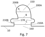
- Fig. 7 is an alternative embodiment of the recess (150) formed in the edge portion of the end plates (10, 15).
- the recess comprises a first asymmetry formed as a second side section (200B) curving more than the first side section (200A), such that the width A of an upper section of the recess (150) is wider than the width B just above the positioning of the locking features (170).
- the term 'upper' is seen in relation to the edge of the end plate (10, 15) comprising the recess (150), just as 'lower' refers to the section close the edge of the respective end plate (10, 15). This asymmetric form assists the bolt from dropping out when the locking device (100, 100A, 100B) is not in positioned and engaged in the locking features (170).
- the recess (150) comprises a second asymmetry, where the second side (210B) of the lower section of the recess (150) has a larger width C than the width B and is positioned asymmetric thereto.
- the recess (150) as illustrated includes both the first and second asymmetries.
- the locking features (170) is formed with rounded endings, rather than squared ones, which improves strength.
Landscapes
- Engineering & Computer Science (AREA)
- General Engineering & Computer Science (AREA)
- Mechanical Engineering (AREA)
- Physics & Mathematics (AREA)
- Thermal Sciences (AREA)
- Heat-Exchange Devices With Radiators And Conduit Assemblies (AREA)
Abstract
Description
- A typical construction of a plate heat exchanger comprises a plurality of heat transfer plate stacked on top of each other. The heat transfer plates are formed with patterns such that flow paths are formed between each set of neighboring heat transfer plates. Openings and are formed in the heat transfer plates defining inlets and outlets for fluids to these flow paths. Some heat exchangers have the plates brazed together, whereas in others heat exchangers gaskets are positioned between the heat transfer plates in gasket grooves formed in the heat transfer plates. The gasket then is arranged at an edge portion of the heat transfer plate to seal the flow paths and at an area around the openings to seal pairs of the openings, such that only two of them have flow access to the flow path formed at one side of the heat transfer plate, while the other two is sealed therefrom.
- Frame plates, or end plates, having a significant thickness compared to the heat transfer plates to take up great loads are connected and fastened to the stack of heat exchangers plates, such as at the top and bottom.
- Such end plates may be held together by bolts inserted into recesses formed in edge portions and tightened by a nut screwed at the one end of the bolt, or one at either side. The problem is that such bolts tend to drop out of the recesses, e.g. during handling of the heat exchanger.
- The present invention solves the problem by the features as given in the claims.
- This includes introducing a heat exchanger comprising a stack of heat transfer plates positioned between two end plates in which recesses formed in edge regions are adapted to accommodate bolts reaching from a first to a second of said two end plates, said at least one of said recesses formed with locking features adapted to engage with a locking device comprising an opening, where the locking device is to be positioned on the respective end plate with the opening aligned with the recess in such a manner that a bolt positioned in the recess also can project through said opening.
- The locking device may be formed with a locking section adapted to match with the locking feature.
- The locking device may comprise a main section formed with said opening and adapted to rest on the surface of said end plate, and the locking section projecting with an angle from said main section such that when in position it fits into said locking feature.
- The locking device may further be formed with engaging sections projecting in an opposite direction relative the locking section adapted to engage with a polygonal end section of the bolt resting on the surface of the main section preventing it from rotation relative to the heat exchanger. In an embodiment the polygonal end section is a nut winded onto the bolt.
- The locking feature may be one or more locking recesses formed in the edge of the recess, forming a first kind locking recess.
- The locking feature may be one or more locking openings formed at the side(s) of the recess, forming a second kind locking recess.
- In an embodiment, a first kind locking device is positioned in connection with a first end plate, and a second kind locking devices positioned in connection with a second end plate, and where a bolt is positioned in a recess of respectively the first and second end plate and projecting trough the openings of respectively the first and second kind locking devices, where tightening means is winded onto the bolt at the end of the first kind locking device resting on its main section.
- In an embodiment the recess (comprises a first asymmetry formed as a second side section curving more than the first side section, such that the width A of an upper section of the recess is wider than the width B just above the positioning of the locking features.
- In an embodiment the recess comprises a second asymmetry, where the second side of the lower section of the recess has a larger width C than the width B and is positioned asymmetric thereto.
- The present invention further relate to a locking device to be used in connection with a heat exchanger comprising a stack of heat transfer plates positioned between two end plates, wherein said locking device comprises a main section adapted to be positioned on the surface of an end plate and is formed with a locking section projecting with an angel relative to the main portion and adapted to match with a locking feature in said end plate.
- In an embodiment, the locking device is formed with engaging sections projecting in an opposite direction relative the locking section adapted to engage with a polygonal end section of a bolt resting on the surface of the main section preventing it from rotation relative to the heat exchanger.
- The present invention further relate to a method to assemble a heat exchanger comprising a stack of heat transfer plates positioned between a first and second end plate each having at least one recesses formed in an edge region, said method being to for locking devices each comprising a main section formed with an opening and a locking section to be positioned with the main section resting on the surface of said end plate) with the opening aligned with the respective end plate recess and the locking section engaging a locking feature of the respective end plate, and positioning a bolt through the aligned openings and recesses of respectively the first and second end plate, said bolt having a polygonal end section positioned on the main section of the first end plate.
- A locking device of a second kind may be positioned on one of the first or second end plates which further is formed with engaging sections projecting in an opposite direction relative the locking section adapted to engage with said polygonal end section of a bolt preventing it from rotation relative to the heat exchanger, and further tightening the first and second end plates together by winding tightening means on the second of the end plates until it rests tightly on the surface of the positioned locking device being of a first kind without engaging sections.
-
- Fig. 1
- Illustration of a plate kind heat exchanger held together by end plates and bolts.
- Fig. 2
- Illustration of recess formed in the edge of an end plate according to a first embodiment of the present invention.
- Figs. 3A-3C
- Illustration of a first kind locking device according to an embodiment of the present invention.
- Figs. 4A-4C
- Illustration of a second kind locking device according to an embodiment of the present invention.
- Figs. 5
- Top view of a second kind locking device installed in a recess in the edge of an end plate.
- Figs. 6
- Side view of a second kind locking device installed in a recess in the edge of an end plate.
- Fig. 7
- Illustration of recess formed in the edge of an end plate according to a second embodiment of the present invention.
- It should be understood, that the detailed description and specific examples, while indicating embodiments of the invention, are given by way of illustration only, since various changes and modifications within the spirit and scope of the invention will become apparent to those skilled in the art from the detailed description.
-
Fig. 1 illustrates one embodiment heat exchanger (1) where a stack of patterned heat transfer plates (5) is positioned between the first end plate (10) and second end plate (15). Not illustrated gaskets or sealings in general are positioned at the edge portions between any two of the connected heat transfer plates (5), such that sealed fluid paths are formed. Since they are not fixed, they are held together by the external forces of squeezing the end plates (10, 15) slightly towards each other. To this end recesses (150) are formed in edge regions adapted to accommodate bolts (25) reaching from a first (10) to a second (15) of the two end plates. At one end the bolt is engage with a polygonal end section (20) which may be an integrally formed part of the bolt (25), such as a bolt head, or may be a nut (20) winded onto a winded end section of the bolt (25). - At the second end of the bolt (25) it is adapted to receive tightening means (21), which too could be a nut (21) screwed to windings at the end of the bolt (25). As illustrated in
fig. 1 the bolt extend from the first end plate (10) to the second end plate (15), and the polygonal end section (20) and tightening means (21) is positioned at the outer end plate (10, 15) surfaces relative to the plate stack (5), such that through the tightening means (21) the two end plates (10, 15) are being squeezed closer together to keep the individual heat transfer plates close together. As indicated, this could be by screwing a nut (21) tighter onto the bolt (25). - An embodiment recess (150) formed in the edge portion of the end plates (10, 15) is illustrated in
fig. 2 . The recess (150) is seen to be open (160) at the edge enabling an easy introduction of the bolt (25) from the sides. This however have the disadvantage that the bolts during handling or operation of the heat exchanger (1) simply may drop out of the recess (150). To solve this problem the end plates (10, 15) are formed with locking features (170). In the illustrated embodiment the locking features (170) is two sub-recesses formed in the side of the recess (150) in parallel to the edge of the end plate (10, 15). Alternatively, they e.g. could be openings formed in the vicinity of the recess (150). - The locking features (170) are adapted to operate with locking sections (110) of locking devices (100) to be used in connection with the bolts (25). An embodiment first kind locking device (100A) is illustrated in
figs. 3A-C and a second kind locking device (100B) is illustrated infigs. 4A-C . - Illustrated in both the first kind locking device (100A) and second kind locking device (100B) is a locking section (110), which in the illustrated embodiment is a bend down section relative to the main section (120). This is adapted to engage with the locking features (170) of the end plates (10, 15), such as formed as recesses or openings/holes. If the locking features (170) are formed as a plural of individual openings, then the locking section (110) preferably would be formed of a similar number of individual parts each adapted to engage with such an opening.
- Further seen in both kinds (100, 100A, 100B) is the main section (120) comprising an opening (125) for a bolt (25).
- The locking device (100, 100A, 100B) operates together with the recess (150), locking features (170) and bolt (25) in a manner where a bolt (25) reaching from the recess (150) of the first end plate (10) to the recess (170) of the second end plate (15) is mounted with respectively the first and second ends reaching through the two openings (125) of the respective locking features (100, 100A, 100B), which is positioned with the locking feature (170) engaging with the locking features (170) preventing any dislocation of the bolt (25), and locking features locking features (100, 100A, 100B), but rather keeps the features in position.
- In an embodiment the locking feature (170) is positioned such, that the inserted bolt (25) will be hold firmly in the recess (150).
- The parts (25, 100, 100A, 100B) further is being fixed such as with a tightening means (20), like a nut being winded onto winded section at the one ends of the bolt (25) till the end plates (10, 15) are slightly squeezed towards each other. This ensures a firm and stable connection and fixation of the heat exchanger (1). At the second end a polygonal end section (20), which in one embodiment too is a nut winded on the second outer end section of the bolt (25), or in an alternative embodiment a head forming part of the bolt (25)
- A remaining problem is preventing the bolt (25) from rotation, both during installation, but also during operation.
- The second kind locking feature (100B) as illustrated in
figs. 4A-C showing engaging sections (130), in the illustrated embodiment formed as wall parts (130) connected to the main section (120) bend in the direction opposite to the locking section (110). The engaging sections (130) are adapted to engage with sides of the polygonal shaped end section (20) when positioned on the main section (120) preventing it from rotation. - In this manner, e.g. tightening means (21) in the form of a nut, can be winded towards the main section (120) of the associated locking device (100A) without having to use an additional tool acting on the polygonal end section (20).
- The polygonal end section (20) could have any shape, such as squared, hexagonal or octagonal.
- The assembly is done, possible attach the locking devices (100, 100A, 100B), tightening means (21) and optionally polygonal end section (20) loosely to the bolt (25). Introducing the whole assembly by the open edges (160) of the recesses (150) and position the locking devices (100, 100A, 100B) on the surfaces of the first (10) and second (15) end plates with their locking sections (110) positioned in the locking features (170). Fixing the parts by the tightening means (21).
- In one embodiment a first kind (100A) locking device is positioned at a first end of the bolt (25), and a second kind (100B) locking device at the second end. The second kind (100B) locking device then is positioned at the end of the polygonal end section (20). The assembly then further introduces the step of positioning the polygonal end section (20) in contact with the engaging sections (130), preventing it from rotation.
-
Fig. 5 is a top view illustration of a polygonal end section (20) positioned in a second kind (100B) locking device with walls in contact with the engaging sections (130) preventing rotation. -
Fig. 6 is a side view of the heat exchanger (1) with the bolts (25) installed according to the embodiment where the polygonal end section (20) is positioned in the second kind (100B) locking device positioned at the upper first end plate (10), and the tightening means (21) positioned at a first kind (100A) locking device positioned at the second end plate (15) at the bottom. The first kind (100A) locking device being formed without any protruding walls like the engaging sections (130) to enable a tool operating on the tightening means (21) when tightening it. The locking features (110) are illustrated positioned into the locking features (170) in the end plates (10, 15). -
Fig. 7 is an alternative embodiment of the recess (150) formed in the edge portion of the end plates (10, 15). In one embodiment of the illustration, the recess comprises a first asymmetry formed as a second side section (200B) curving more than the first side section (200A), such that the width A of an upper section of the recess (150) is wider than the width B just above the positioning of the locking features (170). The term 'upper' is seen in relation to the edge of the end plate (10, 15) comprising the recess (150), just as 'lower' refers to the section close the edge of the respective end plate (10, 15). This asymmetric form assists the bolt from dropping out when the locking device (100, 100A, 100B) is not in positioned and engaged in the locking features (170). - In a further embodiment, the recess (150) comprises a second asymmetry, where the second side (210B) of the lower section of the recess (150) has a larger width C than the width B and is positioned asymmetric thereto.
- In a further asymmetric embodiment, the recess (150) as illustrated includes both the first and second asymmetries.
- In a further embodiment is illustrated that could be implemented in any previously disclosed embodiments, the locking features (170) is formed with rounded endings, rather than squared ones, which improves strength.
Claims (14)
- Heat exchanger (1) comprising a stack of heat transfer plates (5) positioned between two end plates (10, 15) in which recesses (150) formed in edge regions are adapted to accommodate bolts (25) reaching from a first (10) to a second (15) of said two end plates, said at least one of said recesses (150) formed with locking features (170) adapted to engage with a locking device (100) comprising an opening (125), where the locking device (100, 100A, 100B) is to be positioned on the respective end plate (10, 15) with the opening (125) aligned with the recess (150) in such a manner that a bolt (25) positioned in the recess (150) also can project through said opening (125).
- Heat exchanger (1) according to claim 1, wherein said locking device (100, 100A, 100B) is formed with a locking section (110) adapted to match with the locking feature (170).
- Heat exchanger (1) according to claim 2, wherein said locking device (100, 100A, 100B) comprises a main section (120) formed with said opening (125) and adapted to rest on the surface of said end plate (10, 15), and the locking section (110) projecting with an angle from said main section (120) such that when in position it fits into said locking feature (170).
- Heat exchanger according to claim 3, wherein the locking device (100, 100B) further is formed with engaging sections (130) projecting in an opposite direction relative the locking section (110) adapted to engage with a polygonal end section (20) of the bolt (25) resting on the surface of the main section (120) preventing it from rotation relative to the heat exchanger (1).
- Heat exchanger according to claim 4, wherein the polygonal end section is a nut (20) winded onto the bolt (25).
- Heat exchanger (1) according to an of the previous claims, wherein the locking feature (170) is one or more locking recesses formed in the edge of the recess (150).
- Heat exchanger (1) according to any of the previous claims 1-6, wherein the locking feature (170) is one or more locking openings formed at the side(s) of the recess (150).
- Heat exchanger (1) according to any of the previous claims, where a first kind locking device (100A) according to claim 3 is positioned in connection with a first end plate (10), and a second kind locking device (100B) according to claim 4 is positioned in connection with a second end plate (15), and where a bolt (25) is positioned in a recess (150) of respectively the first (10) and second (15) end plate and projecting trough the openings (125) of respectively the first (100A) and second (100B) kind locking devices, where tightening means (21) is winded onto the bolt (25) at the end of the first kind locking device (100A) resting on its main section (120).
- A locking device (100, 100A, 100B) according to any of claims 1-8, wherein the recess (150) comprises a first asymmetry formed as a second side section (200B) curving more than the first side section (200A), such that the width A of an upper section of the recess (150) is wider than the width B just above the positioning of the locking features (170).
- A locking device (100, 100A, 100B) according to any of claims 1-9, wherein the recess (150) comprises a second asymmetry, where the second side (210B) of the lower section of the recess (150) has a larger width C than the width B and is positioned asymmetric thereto.
- A locking device (100, 100A, 100B) to be used in connection with a heat exchanger (1) comprising a stack of heat transfer plates (5) positioned between two end plates (10, 15), wherein said locking device (100) comprises a main section (120) adapted to be positioned on the surface of an end plate (10, 15) and is formed with a locking section (110) projecting with an angel relative to the main portion (120) and adapted to match with a locking feature (170) in said end plate (10, 15).
- A locking device (100, 100A, 100B) according to claim 11, wherein the locking device (100, 100B) further is formed with engaging sections (130) projecting in an opposite direction relative the locking section (110) adapted to engage with a polygonal end section (20) of a bolt (25) resting on the surface of the main section (120) preventing it from rotation relative to the heat exchanger (1).
- Method to assemble a heat exchanger (1) comprising a stack of heat transfer plates (5) positioned between a first (10) and second (15) end plate each having at least one recesses (150) formed in an edge region, said method being to for locking devices (100, 100A, 100B) each comprising a main section (120) formed with an opening (125) and a locking section (110) to be positioned with the main section (120) resting on the surface of said end plate (10, 15) with the opening (125) aligned with the respective end plate (10, 15) recess (150) and the locking section (110) engaging a locking feature (170) of the respective end plate (10, 15), and positioning a bolt (25) through the aligned openings (125) and recesses (150) of respectively the first (10) and second (15) end plate, said bolt (25) having a polygonal end section (20) positioned on the main section (120) of the first end plate (10).
- Method according to claim 13, wherein the locking device (100, 100B) of a second kind positioned on one of the first (10) or second (15) end plates which further is formed with engaging sections (130) projecting in an opposite direction relative the locking section (110) adapted to engage with said polygonal end section (20) of a bolt (25) preventing it from rotation relative to the heat exchanger (1), and further tightening the first (10) and second (15) end plates together by winding tightening means (21) on the second of the end plates (10, 15) until it rests tightly on the surface of the positioned locking device (100, 100A) being of a first kind without engaging sections (130).
Applications Claiming Priority (1)
| Application Number | Priority Date | Filing Date | Title |
|---|---|---|---|
| DKPA202070557 | 2020-08-28 |
Publications (3)
| Publication Number | Publication Date |
|---|---|
| EP3961142A1 true EP3961142A1 (en) | 2022-03-02 |
| EP3961142C0 EP3961142C0 (en) | 2024-06-05 |
| EP3961142B1 EP3961142B1 (en) | 2024-06-05 |
Family
ID=77543351
Family Applications (1)
| Application Number | Title | Priority Date | Filing Date |
|---|---|---|---|
| EP21193714.9A Active EP3961142B1 (en) | 2020-08-28 | 2021-08-30 | Plate kind heat exchanger |
Country Status (5)
| Country | Link |
|---|---|
| US (1) | US12209820B2 (en) |
| EP (1) | EP3961142B1 (en) |
| CN (1) | CN114111391A (en) |
| PL (1) | PL3961142T3 (en) |
| RU (1) | RU2763632C1 (en) |
Families Citing this family (2)
| Publication number | Priority date | Publication date | Assignee | Title |
|---|---|---|---|---|
| CN115265255A (en) * | 2022-08-23 | 2022-11-01 | 安徽普瑞普勒传热技术有限公司 | Detachable efficient plate heat exchanger and assembling method thereof |
| JP7879439B2 (en) * | 2022-09-30 | 2026-06-24 | ダイキン工業株式会社 | Method for manufacturing a refrigerant flow path module, and assembly jig |
Citations (4)
| Publication number | Priority date | Publication date | Assignee | Title |
|---|---|---|---|---|
| JPH04100665U (en) * | 1991-02-05 | 1992-08-31 | ||
| WO1993008438A1 (en) * | 1991-10-25 | 1993-04-29 | Alfa-Laval Food Engineering Ab | Plate heat exchanger |
| EP2474804A1 (en) * | 2011-01-10 | 2012-07-11 | Alfa Laval Corporate AB | Plate heat exchanger |
| EP2672214A1 (en) * | 2012-06-04 | 2013-12-11 | Alfa Laval Corporate AB | End-piece & plate heat exchanger comprising, and method of making, such end-piece |
Family Cites Families (17)
| Publication number | Priority date | Publication date | Assignee | Title |
|---|---|---|---|---|
| GB163229A (en) | 1920-07-26 | 1921-05-19 | Edward Franklin Walker | Improvements in and relating to lock washers |
| US2636533A (en) * | 1946-05-29 | 1953-04-28 | Tinnerman Products Inc | Fastening device |
| US3646982A (en) * | 1969-09-12 | 1972-03-07 | Rex Chainbelt Inc | Encapsulated floating and nonfloating fasteners |
| SU561440A1 (en) * | 1976-06-11 | 1986-02-23 | Предприятие П/Я А-1665 | Plate-type heat exchanger stack and device for manufacturing same |
| GB1553406A (en) * | 1977-05-10 | 1979-09-26 | Apv Co Ltd | Plate heat exchangers |
| GB1553405A (en) * | 1977-06-02 | 1979-09-26 | Apv Co Ltd | Plate heat exchangers |
| US6973960B1 (en) * | 1998-01-16 | 2005-12-13 | Pessach Seidel | Flat plate heat exchanger and flat plate therefor |
| KR100622116B1 (en) * | 2005-08-12 | 2006-09-12 | (주)경원산업 | Heat exchanger plate fixing device of plate heat exchanger |
| SE532197C2 (en) * | 2007-10-15 | 2009-11-10 | Alfa Laval Corp Ab | plate heat exchangers |
| SE533394C2 (en) * | 2008-10-15 | 2010-09-14 | Alfa Laval Corp Ab | A plate heat exchanger |
| SE533205C2 (en) * | 2008-12-03 | 2010-07-20 | Alfa Laval Corp Ab | Heat |
| EP2728293B1 (en) * | 2012-10-30 | 2016-11-23 | Alfa Laval Corporate AB | Heat exchanger plate and plate heat exchanger comprising such a heat exchanger plate |
| CN103016500B (en) * | 2012-12-17 | 2014-12-24 | 贵州精立航太科技有限公司 | High-temperature sealing type two-lug support plate self-locking nut |
| SE1350738A1 (en) * | 2013-06-18 | 2014-12-19 | Scania Cv Ab | Nut device |
| US9702638B2 (en) * | 2015-07-17 | 2017-07-11 | Spx Flow Technology Systems, Inc. | Frame for a heat exchanger |
| CN205878987U (en) * | 2016-07-07 | 2017-01-11 | 天津市津能双鹤热力设备有限公司 | Plate heat exchanger clamping device |
| EP3399270B1 (en) * | 2017-05-03 | 2020-08-19 | Alfa Laval Corporate AB | A plate heat exchanger |
-
2021
- 2021-08-26 RU RU2021125259A patent/RU2763632C1/en active
- 2021-08-27 US US17/459,193 patent/US12209820B2/en active Active
- 2021-08-27 CN CN202110999984.9A patent/CN114111391A/en active Pending
- 2021-08-30 PL PL21193714.9T patent/PL3961142T3/en unknown
- 2021-08-30 EP EP21193714.9A patent/EP3961142B1/en active Active
Patent Citations (4)
| Publication number | Priority date | Publication date | Assignee | Title |
|---|---|---|---|---|
| JPH04100665U (en) * | 1991-02-05 | 1992-08-31 | ||
| WO1993008438A1 (en) * | 1991-10-25 | 1993-04-29 | Alfa-Laval Food Engineering Ab | Plate heat exchanger |
| EP2474804A1 (en) * | 2011-01-10 | 2012-07-11 | Alfa Laval Corporate AB | Plate heat exchanger |
| EP2672214A1 (en) * | 2012-06-04 | 2013-12-11 | Alfa Laval Corporate AB | End-piece & plate heat exchanger comprising, and method of making, such end-piece |
Also Published As
| Publication number | Publication date |
|---|---|
| EP3961142C0 (en) | 2024-06-05 |
| EP3961142B1 (en) | 2024-06-05 |
| CN114111391A (en) | 2022-03-01 |
| US20220065557A1 (en) | 2022-03-03 |
| RU2763632C1 (en) | 2021-12-30 |
| PL3961142T3 (en) | 2024-10-07 |
| US12209820B2 (en) | 2025-01-28 |
Similar Documents
| Publication | Publication Date | Title |
|---|---|---|
| EP3961142B1 (en) | Plate kind heat exchanger | |
| CN102498362B (en) | Heat exchanger with end plate providing mounting flange | |
| KR200472451Y1 (en) | Heat sink module | |
| US6863122B2 (en) | Heat exchanger with nested flange-formed passageway | |
| EP1722184A2 (en) | Coupling structure of heat transfer plate and gasket of plate type heat exchanger | |
| RU2555087C1 (en) | Fixing of sealing gasket in plate heat exchanger | |
| JP5749352B2 (en) | Plate heat exchanger | |
| CN105814388B (en) | Plate Heat Exchanger with Mounting Flanges | |
| EP3640577B1 (en) | Heat exchanger comprising plates with strenghened diagonal area | |
| US10156405B2 (en) | Plate heat exchanger | |
| EP3047224B1 (en) | A plate heat exchanger having reinforcing means | |
| DK177838B1 (en) | A gasketed heat exchanger with elastically deformable dimples | |
| EP3660439B1 (en) | Heat exchanger plate and combination of a heat exchanger plate and a gasket | |
| EP3418664B1 (en) | Plate heat exchanger | |
| WO2023095930A1 (en) | Cup-plate type heat exchanger | |
| WO1983002152A1 (en) | Plate heat exchanger | |
| EP3812682A1 (en) | Lining for heat exchanger | |
| RU2527776C1 (en) | Heat exchanger, heat exchanging plate and method of manufacturing heat exchanger | |
| EP3418665A1 (en) | Plate heat exchanger | |
| KR102654111B1 (en) | Retaining means for heat exchanger plates, gasket arrangement for heat exchanger plates, heat exchanger plates with edge portions and plate heat exchangers | |
| EP3489605A1 (en) | Heat transfer plate for plate heat exchanger and plate heat exchanger with the same | |
| US12135176B2 (en) | Plate heat exchanger gasket | |
| US20140196869A1 (en) | Plate heat exchanger with tension ties | |
| CN209495584U (en) | Tube baffle system for distribution tubes of a plate and shell heat exchanger and plate and shell heat exchanger | |
| EP3396295A1 (en) | Plate heat exchanger |
Legal Events
| Date | Code | Title | Description |
|---|---|---|---|
| PUAI | Public reference made under article 153(3) epc to a published international application that has entered the european phase |
Free format text: ORIGINAL CODE: 0009012 |
|
| STAA | Information on the status of an ep patent application or granted ep patent |
Free format text: STATUS: THE APPLICATION HAS BEEN PUBLISHED |
|
| AK | Designated contracting states |
Kind code of ref document: A1 Designated state(s): AL AT BE BG CH CY CZ DE DK EE ES FI FR GB GR HR HU IE IS IT LI LT LU LV MC MK MT NL NO PL PT RO RS SE SI SK SM TR |
|
| STAA | Information on the status of an ep patent application or granted ep patent |
Free format text: STATUS: REQUEST FOR EXAMINATION WAS MADE |
|
| 17P | Request for examination filed |
Effective date: 20220902 |
|
| RBV | Designated contracting states (corrected) |
Designated state(s): AL AT BE BG CH CY CZ DE DK EE ES FI FR GB GR HR HU IE IS IT LI LT LU LV MC MK MT NL NO PL PT RO RS SE SI SK SM TR |
|
| P01 | Opt-out of the competence of the unified patent court (upc) registered |
Effective date: 20230713 |
|
| STAA | Information on the status of an ep patent application or granted ep patent |
Free format text: STATUS: EXAMINATION IS IN PROGRESS |
|
| 17Q | First examination report despatched |
Effective date: 20230927 |
|
| GRAP | Despatch of communication of intention to grant a patent |
Free format text: ORIGINAL CODE: EPIDOSNIGR1 |
|
| STAA | Information on the status of an ep patent application or granted ep patent |
Free format text: STATUS: GRANT OF PATENT IS INTENDED |
|
| GRAS | Grant fee paid |
Free format text: ORIGINAL CODE: EPIDOSNIGR3 |
|
| INTG | Intention to grant announced |
Effective date: 20240404 |
|
| GRAA | (expected) grant |
Free format text: ORIGINAL CODE: 0009210 |
|
| STAA | Information on the status of an ep patent application or granted ep patent |
Free format text: STATUS: THE PATENT HAS BEEN GRANTED |
|
| AK | Designated contracting states |
Kind code of ref document: B1 Designated state(s): AL AT BE BG CH CY CZ DE DK EE ES FI FR GB GR HR HU IE IS IT LI LT LU LV MC MK MT NL NO PL PT RO RS SE SI SK SM TR |
|
| REG | Reference to a national code |
Ref country code: CH Ref legal event code: EP |
|
| REG | Reference to a national code |
Ref country code: DE Ref legal event code: R096 Ref document number: 602021014019 Country of ref document: DE |
|
| REG | Reference to a national code |
Ref country code: IE Ref legal event code: FG4D |
|
| U01 | Request for unitary effect filed |
Effective date: 20240701 |
|
| U07 | Unitary effect registered |
Designated state(s): AT BE BG DE DK EE FI FR IT LT LU LV MT NL PT SE SI Effective date: 20240708 |
|
| P04 | Withdrawal of opt-out of the competence of the unified patent court (upc) registered |
Free format text: CASE NUMBER: APP_39815/2024 Effective date: 20240704 |
|
| U20 | Renewal fee for the european patent with unitary effect paid |
Year of fee payment: 4 Effective date: 20240705 |
|
| PG25 | Lapsed in a contracting state [announced via postgrant information from national office to epo] |
Ref country code: HR Free format text: LAPSE BECAUSE OF FAILURE TO SUBMIT A TRANSLATION OF THE DESCRIPTION OR TO PAY THE FEE WITHIN THE PRESCRIBED TIME-LIMIT Effective date: 20240605 |
|
| PG25 | Lapsed in a contracting state [announced via postgrant information from national office to epo] |
Ref country code: GR Free format text: LAPSE BECAUSE OF FAILURE TO SUBMIT A TRANSLATION OF THE DESCRIPTION OR TO PAY THE FEE WITHIN THE PRESCRIBED TIME-LIMIT Effective date: 20240906 |
|
| PG25 | Lapsed in a contracting state [announced via postgrant information from national office to epo] |
Ref country code: ES Free format text: LAPSE BECAUSE OF FAILURE TO SUBMIT A TRANSLATION OF THE DESCRIPTION OR TO PAY THE FEE WITHIN THE PRESCRIBED TIME-LIMIT Effective date: 20240605 |
|
| PG25 | Lapsed in a contracting state [announced via postgrant information from national office to epo] |
Ref country code: NO Free format text: LAPSE BECAUSE OF FAILURE TO SUBMIT A TRANSLATION OF THE DESCRIPTION OR TO PAY THE FEE WITHIN THE PRESCRIBED TIME-LIMIT Effective date: 20240905 Ref country code: HR Free format text: LAPSE BECAUSE OF FAILURE TO SUBMIT A TRANSLATION OF THE DESCRIPTION OR TO PAY THE FEE WITHIN THE PRESCRIBED TIME-LIMIT Effective date: 20240605 Ref country code: GR Free format text: LAPSE BECAUSE OF FAILURE TO SUBMIT A TRANSLATION OF THE DESCRIPTION OR TO PAY THE FEE WITHIN THE PRESCRIBED TIME-LIMIT Effective date: 20240906 Ref country code: ES Free format text: LAPSE BECAUSE OF FAILURE TO SUBMIT A TRANSLATION OF THE DESCRIPTION OR TO PAY THE FEE WITHIN THE PRESCRIBED TIME-LIMIT Effective date: 20240605 Ref country code: RS Free format text: LAPSE BECAUSE OF FAILURE TO SUBMIT A TRANSLATION OF THE DESCRIPTION OR TO PAY THE FEE WITHIN THE PRESCRIBED TIME-LIMIT Effective date: 20240905 |
|
| P05 | Withdrawal of opt-out of the competence of the unified patent court (upc) changed |
Free format text: CASE NUMBER: APP_39815/2024 Effective date: 20240708 |
|
| PG25 | Lapsed in a contracting state [announced via postgrant information from national office to epo] |
Ref country code: IS Free format text: LAPSE BECAUSE OF FAILURE TO SUBMIT A TRANSLATION OF THE DESCRIPTION OR TO PAY THE FEE WITHIN THE PRESCRIBED TIME-LIMIT Effective date: 20241005 |
|
| PG25 | Lapsed in a contracting state [announced via postgrant information from national office to epo] |
Ref country code: CZ Free format text: LAPSE BECAUSE OF FAILURE TO SUBMIT A TRANSLATION OF THE DESCRIPTION OR TO PAY THE FEE WITHIN THE PRESCRIBED TIME-LIMIT Effective date: 20240605 |
|
| PG25 | Lapsed in a contracting state [announced via postgrant information from national office to epo] |
Ref country code: RO Free format text: LAPSE BECAUSE OF FAILURE TO SUBMIT A TRANSLATION OF THE DESCRIPTION OR TO PAY THE FEE WITHIN THE PRESCRIBED TIME-LIMIT Effective date: 20240605 Ref country code: SK Free format text: LAPSE BECAUSE OF FAILURE TO SUBMIT A TRANSLATION OF THE DESCRIPTION OR TO PAY THE FEE WITHIN THE PRESCRIBED TIME-LIMIT Effective date: 20240605 |
|
| PG25 | Lapsed in a contracting state [announced via postgrant information from national office to epo] |
Ref country code: SM Free format text: LAPSE BECAUSE OF FAILURE TO SUBMIT A TRANSLATION OF THE DESCRIPTION OR TO PAY THE FEE WITHIN THE PRESCRIBED TIME-LIMIT Effective date: 20240605 |
|
| PG25 | Lapsed in a contracting state [announced via postgrant information from national office to epo] |
Ref country code: SM Free format text: LAPSE BECAUSE OF FAILURE TO SUBMIT A TRANSLATION OF THE DESCRIPTION OR TO PAY THE FEE WITHIN THE PRESCRIBED TIME-LIMIT Effective date: 20240605 Ref country code: SK Free format text: LAPSE BECAUSE OF FAILURE TO SUBMIT A TRANSLATION OF THE DESCRIPTION OR TO PAY THE FEE WITHIN THE PRESCRIBED TIME-LIMIT Effective date: 20240605 Ref country code: RO Free format text: LAPSE BECAUSE OF FAILURE TO SUBMIT A TRANSLATION OF THE DESCRIPTION OR TO PAY THE FEE WITHIN THE PRESCRIBED TIME-LIMIT Effective date: 20240605 Ref country code: IS Free format text: LAPSE BECAUSE OF FAILURE TO SUBMIT A TRANSLATION OF THE DESCRIPTION OR TO PAY THE FEE WITHIN THE PRESCRIBED TIME-LIMIT Effective date: 20241005 Ref country code: CZ Free format text: LAPSE BECAUSE OF FAILURE TO SUBMIT A TRANSLATION OF THE DESCRIPTION OR TO PAY THE FEE WITHIN THE PRESCRIBED TIME-LIMIT Effective date: 20240605 |
|
| REG | Reference to a national code |
Ref country code: CH Ref legal event code: PL |
|
| PLBE | No opposition filed within time limit |
Free format text: ORIGINAL CODE: 0009261 |
|
| STAA | Information on the status of an ep patent application or granted ep patent |
Free format text: STATUS: NO OPPOSITION FILED WITHIN TIME LIMIT |
|
| PG25 | Lapsed in a contracting state [announced via postgrant information from national office to epo] |
Ref country code: MC Free format text: LAPSE BECAUSE OF FAILURE TO SUBMIT A TRANSLATION OF THE DESCRIPTION OR TO PAY THE FEE WITHIN THE PRESCRIBED TIME-LIMIT Effective date: 20240605 Ref country code: CH Free format text: LAPSE BECAUSE OF NON-PAYMENT OF DUE FEES Effective date: 20240831 |
|
| 26N | No opposition filed |
Effective date: 20250306 |
|
| PG25 | Lapsed in a contracting state [announced via postgrant information from national office to epo] |
Ref country code: IE Free format text: LAPSE BECAUSE OF NON-PAYMENT OF DUE FEES Effective date: 20240830 |
|
| U20 | Renewal fee for the european patent with unitary effect paid |
Year of fee payment: 5 Effective date: 20250709 |
|
| PGFP | Annual fee paid to national office [announced via postgrant information from national office to epo] |
Ref country code: PL Payment date: 20250714 Year of fee payment: 5 |
|
| PG25 | Lapsed in a contracting state [announced via postgrant information from national office to epo] |
Ref country code: CY Free format text: LAPSE BECAUSE OF FAILURE TO SUBMIT A TRANSLATION OF THE DESCRIPTION OR TO PAY THE FEE WITHIN THE PRESCRIBED TIME-LIMIT; INVALID AB INITIO Effective date: 20210830 |
|
| PG25 | Lapsed in a contracting state [announced via postgrant information from national office to epo] |
Ref country code: HU Free format text: LAPSE BECAUSE OF FAILURE TO SUBMIT A TRANSLATION OF THE DESCRIPTION OR TO PAY THE FEE WITHIN THE PRESCRIBED TIME-LIMIT; INVALID AB INITIO Effective date: 20210830 |
|
| GBPC | Gb: european patent ceased through non-payment of renewal fee |
Effective date: 20250830 |
|
| PG25 | Lapsed in a contracting state [announced via postgrant information from national office to epo] |
Ref country code: TR Free format text: LAPSE BECAUSE OF FAILURE TO SUBMIT A TRANSLATION OF THE DESCRIPTION OR TO PAY THE FEE WITHIN THE PRESCRIBED TIME-LIMIT Effective date: 20240605 |
|
| PG25 | Lapsed in a contracting state [announced via postgrant information from national office to epo] |
Ref country code: GB Free format text: LAPSE BECAUSE OF NON-PAYMENT OF DUE FEES Effective date: 20250830 |