EP3961133A1 - Water outlet mechanism and refrigerator having water outlet mechanism - Google Patents
Water outlet mechanism and refrigerator having water outlet mechanism Download PDFInfo
- Publication number
- EP3961133A1 EP3961133A1 EP19925808.8A EP19925808A EP3961133A1 EP 3961133 A1 EP3961133 A1 EP 3961133A1 EP 19925808 A EP19925808 A EP 19925808A EP 3961133 A1 EP3961133 A1 EP 3961133A1
- Authority
- EP
- European Patent Office
- Prior art keywords
- water outlet
- inner tube
- support
- water
- sealing ring
- Prior art date
- Legal status (The legal status is an assumption and is not a legal conclusion. Google has not performed a legal analysis and makes no representation as to the accuracy of the status listed.)
- Granted
Links
Images




Classifications
-
- F—MECHANICAL ENGINEERING; LIGHTING; HEATING; WEAPONS; BLASTING
- F25—REFRIGERATION OR COOLING; COMBINED HEATING AND REFRIGERATION SYSTEMS; HEAT PUMP SYSTEMS; MANUFACTURE OR STORAGE OF ICE; LIQUEFACTION SOLIDIFICATION OF GASES
- F25D—REFRIGERATORS; COLD ROOMS; ICE-BOXES; COOLING OR FREEZING APPARATUS NOT OTHERWISE PROVIDED FOR
- F25D11/00—Self-contained movable devices, e.g. domestic refrigerators
-
- F—MECHANICAL ENGINEERING; LIGHTING; HEATING; WEAPONS; BLASTING
- F25—REFRIGERATION OR COOLING; COMBINED HEATING AND REFRIGERATION SYSTEMS; HEAT PUMP SYSTEMS; MANUFACTURE OR STORAGE OF ICE; LIQUEFACTION SOLIDIFICATION OF GASES
- F25D—REFRIGERATORS; COLD ROOMS; ICE-BOXES; COOLING OR FREEZING APPARATUS NOT OTHERWISE PROVIDED FOR
- F25D23/00—General constructional features
- F25D23/12—Arrangements of compartments additional to cooling compartments; Combinations of refrigerators with other equipment, e.g. stove
- F25D23/126—Water cooler
-
- B—PERFORMING OPERATIONS; TRANSPORTING
- B67—OPENING, CLOSING OR CLEANING BOTTLES, JARS OR SIMILAR CONTAINERS; LIQUID HANDLING
- B67D—DISPENSING, DELIVERING OR TRANSFERRING LIQUIDS, NOT OTHERWISE PROVIDED FOR
- B67D1/00—Apparatus or devices for dispensing beverages on draught
- B67D1/08—Details
- B67D1/12—Flow or pressure control devices or systems, e.g. valves, gas pressure control, level control in storage containers
- B67D1/1202—Flow control, e.g. for controlling total amount or mixture ratio of liquids to be dispensed
- B67D1/1234—Flow control, e.g. for controlling total amount or mixture ratio of liquids to be dispensed to determine the total amount
- B67D1/124—Flow control, e.g. for controlling total amount or mixture ratio of liquids to be dispensed to determine the total amount the flow being started or stopped by means actuated by the vessel to be filled, e.g. by switches, weighing
-
- B—PERFORMING OPERATIONS; TRANSPORTING
- B67—OPENING, CLOSING OR CLEANING BOTTLES, JARS OR SIMILAR CONTAINERS; LIQUID HANDLING
- B67D—DISPENSING, DELIVERING OR TRANSFERRING LIQUIDS, NOT OTHERWISE PROVIDED FOR
- B67D1/00—Apparatus or devices for dispensing beverages on draught
- B67D1/08—Details
- B67D1/12—Flow or pressure control devices or systems, e.g. valves, gas pressure control, level control in storage containers
- B67D1/1277—Flow control valves
-
- B—PERFORMING OPERATIONS; TRANSPORTING
- B67—OPENING, CLOSING OR CLEANING BOTTLES, JARS OR SIMILAR CONTAINERS; LIQUID HANDLING
- B67D—DISPENSING, DELIVERING OR TRANSFERRING LIQUIDS, NOT OTHERWISE PROVIDED FOR
- B67D3/00—Apparatus or devices for controlling flow of liquids under gravity from storage containers for dispensing purposes
- B67D3/0009—Apparatus or devices for controlling flow of liquids under gravity from storage containers for dispensing purposes provided with cooling arrangements
-
- B—PERFORMING OPERATIONS; TRANSPORTING
- B67—OPENING, CLOSING OR CLEANING BOTTLES, JARS OR SIMILAR CONTAINERS; LIQUID HANDLING
- B67D—DISPENSING, DELIVERING OR TRANSFERRING LIQUIDS, NOT OTHERWISE PROVIDED FOR
- B67D3/00—Apparatus or devices for controlling flow of liquids under gravity from storage containers for dispensing purposes
- B67D3/0025—Apparatus or devices for controlling flow of liquids under gravity from storage containers for dispensing purposes provided with dispensing valves actuated by the receptacle to be filled
-
- B—PERFORMING OPERATIONS; TRANSPORTING
- B67—OPENING, CLOSING OR CLEANING BOTTLES, JARS OR SIMILAR CONTAINERS; LIQUID HANDLING
- B67D—DISPENSING, DELIVERING OR TRANSFERRING LIQUIDS, NOT OTHERWISE PROVIDED FOR
- B67D3/00—Apparatus or devices for controlling flow of liquids under gravity from storage containers for dispensing purposes
- B67D3/02—Liquid-dispensing valves having operating members arranged to be pressed upwards, e.g. by the rims of receptacles held below the delivery orifice
-
- F—MECHANICAL ENGINEERING; LIGHTING; HEATING; WEAPONS; BLASTING
- F25—REFRIGERATION OR COOLING; COMBINED HEATING AND REFRIGERATION SYSTEMS; HEAT PUMP SYSTEMS; MANUFACTURE OR STORAGE OF ICE; LIQUEFACTION SOLIDIFICATION OF GASES
- F25D—REFRIGERATORS; COLD ROOMS; ICE-BOXES; COOLING OR FREEZING APPARATUS NOT OTHERWISE PROVIDED FOR
- F25D23/00—General constructional features
- F25D23/12—Arrangements of compartments additional to cooling compartments; Combinations of refrigerators with other equipment, e.g. stove
-
- B—PERFORMING OPERATIONS; TRANSPORTING
- B67—OPENING, CLOSING OR CLEANING BOTTLES, JARS OR SIMILAR CONTAINERS; LIQUID HANDLING
- B67D—DISPENSING, DELIVERING OR TRANSFERRING LIQUIDS, NOT OTHERWISE PROVIDED FOR
- B67D2210/00—Indexing scheme relating to aspects and details of apparatus or devices for dispensing beverages on draught or for controlling flow of liquids under gravity from storage containers for dispensing purposes
- B67D2210/00028—Constructional details
- B67D2210/00031—Housing
- B67D2210/00034—Modules
- B67D2210/00036—Modules for use with or in refrigerators
Definitions
- the present invention relates to the technical field of household appliance, to a water outlet mechanism and particularly to a refrigerator having the water outlet mechanism.
- a conventional refrigerator has a structural design with a function of providing iced water. As shown in FIG. 1 through FIG. 4 , a spout 1 of the structure is generally prevented from water overflow by building a check value 5 in the spout 1 and by fixing a sealing ring 3.
- the pressure of water in a water tube 2 is controlled by turning on or off a water valve, and the opening and closing of the check valve 5 is controlled through the water pressure to achieve water supply.
- a first step 14 is formed between a fitting port 13 and a spout inner tube 11, the sealing ring 3 is disposed on a step surface of the first step 14, and the check valve 5 is disposed in the interior of the spout inner tube 11.
- the sealing ring 3 and other portions of the spout 1 move together from the lower left to the upper right so that the water tube 2 is inserted into the spout inner tube 11.
- the present invention provides a water outlet mechanism, and a refrigerator including the water outlet mechanism.
- an embodiment of the present invention provides a water outlet mechanism, comprising:
- the support is configured as a cylindrical shape, and an end of the water tube runs through the support or is located in the support.
- a step is provided on the inner wall of the spout inner tube, and the support is at least partially disposed between the step and the sealing ring.
- the support is configured as a T-shaped cylinder comprising a supporting portion and a flange portion, the flange portion has a circular ring shape, one side of the flange portion abuts against the step, and the other side of the flange portion abuts against the sealing ring, and the supporting portion is connected to the flange portion and extends toward the check valve and assumes a cylindrical structure.
- the support is configured as a circular ring cylinder, one end of the circular ring cylinder abuts against the step, the other end of the circular ring cylinder abuts against the sealing ring, and a width of the circular ring of the circular ring cylinder is greater than the width of the step.
- the support is configured as a hollow sleeve, one end of the hollow sleeve abuts against the check valve, and the other end of the hollow sleeve abuts against the sealing ring.
- the spout inner tube is circular, an outer surface of the support is circular, and an outer diameter of the support is smaller than or equal to an inner diameter of the spout inner tube.
- the water tube comprises a water tube body defining the end of the water tube, and an assembly terminal sleeved on the outside of the water tube body, and wherein when the end of the water tube extends through the fitting port into the spout inner tube, the assembly terminal limits the sealing ring.
- an embodiment of the present invention provides a refrigerator comprising the water outlet mechanism.
- the refrigerator comprises a dispenser that comprises the water outlet mechanism.
- the present embodiment has the following advantageous effects: in the water outlet mechanism, the support abutting against the sealing ring is disposed; in the case that it is ensured that the check valve can be mounted in the spout inner tube, at least partial space between the sealing ring and the check valve is filled by the support, the area of the supporting surface of the sealing ring is increased, and the sealing ring is not prone to deviate from its fitting position due to the assembling of the water tube, thereby solving the phenomenon of water overflow caused by incomplete sealing of the sealing ring.
- a spout 11. a spout inner tube; 12. a water outlet; 13. a fitting port; 14. a first step; 15. a second step; 2. a water tube; 21. a water tube body; 22. an assembly terminal; 3. a sealing ring; 4. a support; 4a. a T-shaped cylinder; 411. a flange portion; 412. a supporting portion;4b. a circular ring cylinder; 4c. a hollow sleeve; 5. a check valve; 6. a press button;
- An embodiment of the present invention provides a water outlet mechanism, which may be applied to a refrigerator, that is, the present embodiment also provides a refrigerator having the water outlet mechanism.
- the present embodiment is not limited thereto.
- the refrigerator comprises a dispenser
- the dispenser comprises the water outlet mechanism
- the water outlet mechanism is used for supplying iced water.
- An iced water making device is disposed in a refrigerating chamber of the refrigerator and connected to the water outlet mechanism.
- the iced water making device comprises a water valve for opening/closing the water outlet mechanism.
- the water outlet mechanism comprises a spout 1, a water tube 2, a check valve 5 and a sealing ring 3.
- the spout 1 has a hollow spout inner tube 11, a water outlet 12 formed at one end of the spout inner tube 11, and a fitting port 13 formed at the other end of the spout inner tube 11, an end of the water tube 2 extending from the fitting port 13 through the fitting port 13 into the spout inner tube 11;
- the check valve 5 is disposed in the spout inner tube 11 and can disengage from the spout inner tube 11 through the fitting port 13, a second step 15 is formed in the spout inner tube 11, one end of the check valve 5 abuts against the second step 15, and the second step 15 restricts the movement of the check valve 5 toward the water outlet 12;
- the check valve 5 has an open state and a closed state, to control the remaining water in the water tube 2 and the spout inner tube 11 not to flow out.
- the refrigerator is provided with a press button 6 which serves as a switch.
- the press button 6 is triggered to control the opening and closing of the water valve.
- the water valve controls water to flow into or out of the water tube 2.
- the water pressure drives the check valve 5 to open, and water flows out of the water outlet 12 of the spout 1.
- the check valve 5 closes the water outlet 12, and the water in the water tube 2 and the spout inner tube 11 remains inside.
- the sealing ring 3 is sealingly sleeved between the outside of the water tube 2 and the inside of the spout 1, and the sealing ring 3 restricts the water in the spout inner tube 11 from overflowing from the fitting port 13; the sealing ring 3 is elastic. While the water tube 2 is inserted through the fitting port 13 into the spout inner tube 11, the sealing ring 3 is pressed by the water tube 2 and the spout 1 to deform elastically to fill a gap between the water tube 2 and the spout inner tube 11. As shown in FIG. 5 or FIG. 6 , the spout 1 moves towards the upper right as shown until the water tube 2 is inserted from the lower left into the interior of the spout inner tube 2.
- a direction in which the water tube 2 moves relative to the spout 1 is set as a first direction, namely, the lower left as shown.
- the water in the water tube 2 flows towards the lower left.
- the sealing ring 3 restricts the water from overflowing towards the fitting port 13 on the upper right.
- the water outlet mechanism further comprises a support 4, which supports the sealing ring 3, so that the sealing ring 3 is not prone to misalignment such that water overflow is impossible.
- the water outlet mechanism further comprises: a support 4 disposed in the spout inner tube 11, wherein the sealing ring 3 abuts against a side of the support 4 facing away from the check valve 5, the support 4 extends from the spout 1 towards a central axis of the spout inner tube 11, the movement of the support in the first direction is restricted, and the sealing ring 3 abuts against the support 4.
- the water tube 2 comprises a water tube body 21 defining the end of the water tube 2, and an assembly terminal 22 sleeved on the outside of the water tube 2 body.
- the assembly terminal 22 abuts against the sealing ring 3, and the assembly terminal 22 prevents the sealing ring 3 from moving in a direction opposite to the first direction.
- the support 4 is configured as a cylindrical shape, the water tube 2 runs through the cylindrical support 4, and the cylindrical structure of the support 4 is adapted for the space in the spout inner tube 11.
- a cross section of the spout inner tube 11 is circular.
- the cross-section of a surface adapted for the spout inner tube 11 is also circular.
- An outer diameter of the spout inner tube 11 is smaller than an inner diameter of the spout inner tube 11. If the cross section of the spout inner tube 11 is set in other shapes, the cross section of the support 4 is also made in the corresponding shapes.
- a step is provided on a side wall of the spout inner tube 11, the support 4 is provided between the step and the sealing ring 3, the step is named the first step 14 in the figures, and the support 4 abuts against the first step 14.
- the support 4 is configured as a T-shaped cylinder 4a.
- the T-shaped cylinder 4a comprises a supporting portion 412 and a flange portion 411.
- the flange portion 411 has a circular ring shape.
- One side of the flange portion 411 abuts against the step, and the other side of the flange portion 411 abuts against the sealing ring 3.
- the supporting portion 412 is connected to the flange portion 411 and extends out of the cylinder toward the check valve 5.
- the supporting portion 412 is inserted into the spout inner tube 11 in the first direction until the flange portion 411 abuts the first step 14, and then the sealing ring 3 is mounted into the spout inner cylinder 11 from the fitting port 13 until the sealing ring 3 abuts the other side of the flange portion 411.
- the water tube 2 is inserted into the flange portion 411 and the supporting portion 412.
- the first step 14 restricts the movement of the T-shaped cylinder 4a in the first direction.
- the flange portion 411 abuts against the first step 14.
- the supporting portion 412 reduces the area of the gap in the spout inner tube 11 except for the water tube 2, and restricts the movement of the support 4 in the spout inner tube 11, so that the support 4 supports itself and the sealing ring 3 more stably and meanwhile supports the water tube 2 and prevents water overflow caused by the misalignment of the support 4 and the sealing ring 3 when the water tube 2 is inserted.
- the cross section of the flange portion 411 perpendicular to the first direction is a circular ring.
- a width of the circular ring of flange portion 411 is greater than a step height of the first step 14 and smaller than the width of the circular ring of the sealing ring 3;
- the flange portion 411 can provide a larger supporting area relative to the first step 14, so that it supports the sealing ring 3 more stably.
- the sealing ring 3 is in a interference-fitted state between the water tube 2 and the spout 1 to function to support, it achieves the sealing effect.
- the width of the circular ring of the flange portion 411 is made smaller than the width of the circular ring of the sealing ring 3, which can be better implemented.
- the present embodiment has the following advantageous effects: in the water outlet mechanism, the support 4 abutting against the sealing ring 3 is disposed; in the case that it is ensured that the check valve 5 can be mounted in the spout inner tube 11, at least partial space between the sealing ring 3 and the check valve 5 is filled by the support 4, the area of the supporting surface of the sealing ring 3 is increased, and the sealing ring 3 is not prone to deviate from its fitting position due to the assembling of the water tube 2, thereby solving the phenomenon of water overflow caused by incomplete sealing of the sealing ring 3.
- Embodiment 1 only lies in the structure of the support 4. The difference will be described in detail below, and other portions that are the same as those in Embodiment 1 will not be detailed any more here.
- the support 4 is configured as a circular ring cylinder 4b, an inner wall of the spout inner tube 11 forms the first step 14, and the circular ring tube 4b and the sealing ring 3 are sequentially inserted through the fitting port 13 into the spout inner tube 11 in the first direction until one end of the circular ring cylinder 4b abuts against the first step 14, the other end of the circular ring cylinder 4b abuts against the sealing ring 3, and the water tube 2 runs through the sealing ring 3 and the circular ring cylinder 4b.
- the sealing ring 3 and the first step 14 are separated by the circular ring cylinder 4b.
- the circular ring cylinder 4b is not prone to deformation. That is, when the water tube 2 presses the sealing ring 3 to thereby exert a pressure on the circular ring cylinder 4b, the circular ring cylinder 4b is not deformed and pressed into between the first step 14 and the check valve 5, thereby restricting the sealing ring 3 from misalignment and thereby avoiding occurrence of the problem about overflow as stated in the BACKGROUND.
- the width of the circular ring of the circular ring cylinder 4b is greater than the step height of the first step 14 and smaller than the width of the circular ring of the sealing ring 3. Since the width of the circular ring of the circular ring cylinder 4b is larger, the circular ring cylinder 4b provides a larger supporting area relative to the first step 14 and supports the sealing ring 3 more stably.
- Embodiment 1 only lies in the structure of the support 4. The difference will be described in detail below, and other portions that are the same as those in Embodiment 1 will not be detailed any more here.
- the support 4 is configured as a hollow sleeve 4c.
- One end of the hollow sleeve 4c abuts against the check valve 5, and the other end of the hollow sleeve 4c abuts against the sealing ring 3.
- what supports the sealing ring 3 may be the hollow sleeve 4c.
- the inner wall of the spout inner tube 11 is a straight wall
- the check valve 5 restricts the movement of the hollow sleeve 4c in the first direction
- the gap between the spout inner tube 11 and the water tube 2 is filled by the hollow sleeve 4c.
- the inner wall of the spout inner tube 11 forms the first step 14; one end of the hollow sleeve 4c abutting against the sealing ring 3 is flush with the step surface of the first step 14, that is, the sealing ring 3 is jointly supported by the first step 14 and the hollow sleeve 4c; while the hollow sleeve 4c fills the spout inner tube 11, it also supports the sealing ring 3.
- the present embodiment has higher requirements for fitting accuracy and can also solve the technical problem to be solved by the present invention.
Landscapes
- Engineering & Computer Science (AREA)
- Mechanical Engineering (AREA)
- Chemical & Material Sciences (AREA)
- Combustion & Propulsion (AREA)
- Physics & Mathematics (AREA)
- Thermal Sciences (AREA)
- General Engineering & Computer Science (AREA)
- Check Valves (AREA)
Abstract
Description
- The present invention relates to the technical field of household appliance, to a water outlet mechanism and particularly to a refrigerator having the water outlet mechanism.
- A conventional refrigerator has a structural design with a function of providing iced water. As shown in
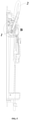
FIG. 1 through FIG. 4 , aspout 1 of the structure is generally prevented from water overflow by building acheck value 5 in thespout 1 and by fixing asealing ring 3. The pressure of water in awater tube 2 is controlled by turning on or off a water valve, and the opening and closing of thecheck valve 5 is controlled through the water pressure to achieve water supply. - Specifically, in
FIG. 4 , afirst step 14 is formed between afitting port 13 and a spoutinner tube 11, thesealing ring 3 is disposed on a step surface of thefirst step 14, and thecheck valve 5 is disposed in the interior of the spoutinner tube 11. The sealingring 3 and other portions of thespout 1 move together from the lower left to the upper right so that thewater tube 2 is inserted into the spoutinner tube 11. However, since the size and structure of thecheck valve 5 and the space limitation of theentire spout 1 cause a bearing surface of thesealing ring 3 too small, it is very liable to occur during the mounting of thespout 1 that thewater tube 2 drives thesealing ring 3 offset from the fitting position to between thefirst step 14 and thecheck valve 5, so that the sealing ring fails to function to seal, and water leakage from the position of thesealing ring 3 might occur during actual use. - To solve the problems about water leakage caused by incomplete sealing in the prior art, the present invention provides a water outlet mechanism, and a refrigerator including the water outlet mechanism.
- To achieve one of the above objects of the present invention, an embodiment of the present invention provides a water outlet mechanism, comprising:
- a spout having a hollow spout inner tube, a water outlet formed at one end of the spout inner tube, and a fitting port formed at the other end of the spout inner tube;
- a check valve which is disposed in the spout inner tube and can disengage from the spout inner tube through the fitting port;
- a water tube whose end extends through the fitting port into the spout inner tube;
- a sealing ring sealingly sleeved between the outside of the water tube and the inside of the spout;
- a support disposed in the spout inner tube, the sealing ring abutting against a side of the support facing away from the check valve, the support extending from an inner wall of the spout inner tube towards a central axis of the spout inner tube.
- As a further improvement of an embodiment of the present invention, the support is configured as a cylindrical shape, and an end of the water tube runs through the support or is located in the support.
- As a further improvement of an embodiment of the present invention, a step is provided on the inner wall of the spout inner tube, and the support is at least partially disposed between the step and the sealing ring.
- As a further improvement of an embodiment of the present invention, the support is configured as a T-shaped cylinder comprising a supporting portion and a flange portion, the flange portion has a circular ring shape, one side of the flange portion abuts against the step, and the other side of the flange portion abuts against the sealing ring, and the supporting portion is connected to the flange portion and extends toward the check valve and assumes a cylindrical structure.
- As a further improvement of an embodiment of the present invention, the support is configured as a circular ring cylinder, one end of the circular ring cylinder abuts against the step, the other end of the circular ring cylinder abuts against the sealing ring, and a width of the circular ring of the circular ring cylinder is greater than the width of the step.
- As a further improvement of an embodiment of the present invention, the support is configured as a hollow sleeve, one end of the hollow sleeve abuts against the check valve, and the other end of the hollow sleeve abuts against the sealing ring.
- As a further improvement of an embodiment of the present invention, in a cross section of the water outlet mechanism, the spout inner tube is circular, an outer surface of the support is circular, and an outer diameter of the support is smaller than or equal to an inner diameter of the spout inner tube.
- As a further improvement of an embodiment of the present invention, the water tube comprises a water tube body defining the end of the water tube, and an assembly terminal sleeved on the outside of the water tube body, and wherein when the end of the water tube extends through the fitting port into the spout inner tube, the assembly terminal limits the sealing ring.
- To achieve one of the above objects of the present invention, an embodiment of the present invention provides a refrigerator comprising the water outlet mechanism.
- As a further improvement of an embodiment of the present invention, the refrigerator comprises a dispenser that comprises the water outlet mechanism.
- As compared with the prior art, the present embodiment has the following advantageous effects: in the water outlet mechanism, the support abutting against the sealing ring is disposed; in the case that it is ensured that the check valve can be mounted in the spout inner tube, at least partial space between the sealing ring and the check valve is filled by the support, the area of the supporting surface of the sealing ring is increased, and the sealing ring is not prone to deviate from its fitting position due to the assembling of the water tube, thereby solving the phenomenon of water overflow caused by incomplete sealing of the sealing ring.
-
-
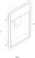
FIG. 1 is a schematic structural diagram of a conventional water outlet mechanism; -
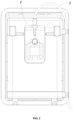
FIG. 2 is a rear view of the conventional water outlet mechanism; -
FIG. 3 is a cross-sectional view of the conventional water outlet mechanism; -
FIG. 4 is a partial enlarged view of the conventional water outlet mechanism at position A ofFIG. 3 ; -
FIG. 5 is a cross-sectional view of a water outlet mechanism according toEmbodiment 1 of the present invention; -
FIG. 6 is a partial enlarged view of position B of the water outlet mechanism according toembodiment 1 of the present invention; -
FIG. 7 is a cross-sectional view of a support of the water outlet mechanism according to the first embodiment of the present invention; -
FIG. 8 is a cross-sectional view of a support of a water outlet mechanism according toEmbodiment 2 of the present invention; -
FIG. 9 is a cross-sectional view of a support of a water outlet mechanism according toEmbodiment 3 of the present invention; - Wherein: 1. a spout; 11. a spout inner tube; 12. a water outlet; 13. a fitting port; 14. a first step; 15. a second step; 2. a water tube; 21. a water tube body; 22. an assembly terminal; 3. a sealing ring; 4. a support; 4a. a T-shaped cylinder; 411. a flange portion; 412. a supporting portion;4b. a circular ring cylinder; 4c. a hollow sleeve; 5. a check valve; 6. a press button;
- The present invention will be described in detail below in conjunction with specific embodiments shown in the figures. However, these embodiments are not intended to limit the present invention. Variations in structures, methods or functions made by those having ordinary skill in the art according to these embodiments are all comprised in the extent of protection of the present invention.
- An embodiment of the present invention provides a water outlet mechanism, which may be applied to a refrigerator, that is, the present embodiment also provides a refrigerator having the water outlet mechanism. Certainly, the present embodiment is not limited thereto.
- In the present embodiment, as shown in
FIGS. 1 through 2 andFIGS. 5 through 9 , the refrigerator comprises a dispenser, the dispenser comprises the water outlet mechanism, and the water outlet mechanism is used for supplying iced water. An iced water making device is disposed in a refrigerating chamber of the refrigerator and connected to the water outlet mechanism. The iced water making device comprises a water valve for opening/closing the water outlet mechanism. - Specifically, the water outlet mechanism comprises a
spout 1, awater tube 2, acheck valve 5 and asealing ring 3. Thespout 1 has a hollow spoutinner tube 11, awater outlet 12 formed at one end of the spoutinner tube 11, and afitting port 13 formed at the other end of the spoutinner tube 11, an end of thewater tube 2 extending from thefitting port 13 through thefitting port 13 into the spoutinner tube 11; thecheck valve 5 is disposed in the spoutinner tube 11 and can disengage from the spoutinner tube 11 through thefitting port 13, asecond step 15 is formed in the spoutinner tube 11, one end of thecheck valve 5 abuts against thesecond step 15, and thesecond step 15 restricts the movement of thecheck valve 5 toward thewater outlet 12; thecheck valve 5 has an open state and a closed state, to control the remaining water in thewater tube 2 and the spoutinner tube 11 not to flow out. - The refrigerator is provided with a
press button 6 which serves as a switch. Thepress button 6 is triggered to control the opening and closing of the water valve. The water valve controls water to flow into or out of thewater tube 2. When the water valve is opened, the water pressure drives thecheck valve 5 to open, and water flows out of thewater outlet 12 of thespout 1. When the water valve is closed, the water pressure in thewater tube 2 weakens and does not suffice to open thecheck valve 5, thecheck valve 5 closes thewater outlet 12, and the water in thewater tube 2 and the spoutinner tube 11 remains inside. - The sealing
ring 3 is sealingly sleeved between the outside of thewater tube 2 and the inside of thespout 1, and thesealing ring 3 restricts the water in the spoutinner tube 11 from overflowing from thefitting port 13; the sealingring 3 is elastic. While thewater tube 2 is inserted through thefitting port 13 into the spoutinner tube 11, the sealingring 3 is pressed by thewater tube 2 and thespout 1 to deform elastically to fill a gap between thewater tube 2 and the spoutinner tube 11. As shown inFIG. 5 orFIG. 6 , thespout 1 moves towards the upper right as shown until thewater tube 2 is inserted from the lower left into the interior of the spoutinner tube 2. A direction in which thewater tube 2 moves relative to thespout 1 is set as a first direction, namely, the lower left as shown. The water in thewater tube 2 flows towards the lower left. The sealingring 3 restricts the water from overflowing towards thefitting port 13 on the upper right. - As mentioned in the BACKGROUND, it is very liable to occur during the mounting of the
spout 1 that thewater tube 2 drives the sealingring 3 offset from the fitting position to between thefirst step 14 and thecheck valve 5, so that the sealing ring fails to function to seal, and water leakage from the position of the sealingring 3 might occur during actual use. - In the present invention, the water outlet mechanism further comprises a support 4, which supports the sealing
ring 3, so that the sealingring 3 is not prone to misalignment such that water overflow is impossible. The technical solutions of the present invention will be introduced below in conjunction with three specific embodiments of the water outlet mechanism shown in the figures. The extent of protection of the present invention is not limited thereto. All improvements mentioned in the embodiments may be adaptively applied to other water outlet mechanisms. - The water outlet mechanism further comprises:
a support 4 disposed in the spoutinner tube 11, wherein the sealingring 3 abuts against a side of the support 4 facing away from thecheck valve 5, the support 4 extends from thespout 1 towards a central axis of the spoutinner tube 11, the movement of the support in the first direction is restricted, and thesealing ring 3 abuts against the support 4. - The
water tube 2 comprises awater tube body 21 defining the end of thewater tube 2, and anassembly terminal 22 sleeved on the outside of thewater tube 2 body. When the end of thewater tube 2 extends through thefitting port 13 into the spoutinner tube 11, theassembly terminal 22 abuts against the sealingring 3, and theassembly terminal 22 prevents the sealingring 3 from moving in a direction opposite to the first direction. - The support 4 is configured as a cylindrical shape, the
water tube 2 runs through the cylindrical support 4, and the cylindrical structure of the support 4 is adapted for the space in the spoutinner tube 11. In general, a cross section of the spoutinner tube 11 is circular. The cross-section of a surface adapted for the spoutinner tube 11 is also circular. An outer diameter of the spoutinner tube 11 is smaller than an inner diameter of the spoutinner tube 11. If the cross section of the spoutinner tube 11 is set in other shapes, the cross section of the support 4 is also made in the corresponding shapes. - A step is provided on a side wall of the spout
inner tube 11, the support 4 is provided between the step and thesealing ring 3, the step is named thefirst step 14 in the figures, and the support 4 abuts against thefirst step 14. - In the present embodiment, the support 4 is configured as a T-shaped
cylinder 4a. As shown inFIG. 6 orFIG. 7 , the T-shapedcylinder 4a comprises a supporting portion 412 and a flange portion 411. The flange portion 411 has a circular ring shape. One side of the flange portion 411 abuts against the step, and the other side of the flange portion 411 abuts against the sealingring 3. The supporting portion 412 is connected to the flange portion 411 and extends out of the cylinder toward thecheck valve 5. The supporting portion 412 is inserted into the spoutinner tube 11 in the first direction until the flange portion 411 abuts thefirst step 14, and then the sealingring 3 is mounted into the spoutinner cylinder 11 from thefitting port 13 until the sealingring 3 abuts the other side of the flange portion 411. Thewater tube 2 is inserted into the flange portion 411 and the supporting portion 412. Thefirst step 14 restricts the movement of the T-shapedcylinder 4a in the first direction. - The flange portion 411 abuts against the
first step 14. The supporting portion 412 reduces the area of the gap in the spoutinner tube 11 except for thewater tube 2, and restricts the movement of the support 4 in the spoutinner tube 11, so that the support 4 supports itself and thesealing ring 3 more stably and meanwhile supports thewater tube 2 and prevents water overflow caused by the misalignment of the support 4 and thesealing ring 3 when thewater tube 2 is inserted. - Furthermore, the cross section of the flange portion 411 perpendicular to the first direction is a circular ring. A width of the circular ring of flange portion 411 is greater than a step height of the
first step 14 and smaller than the width of the circular ring of the sealingring 3; As such, the flange portion 411 can provide a larger supporting area relative to thefirst step 14, so that it supports the sealingring 3 more stably. Since the sealingring 3 is in a interference-fitted state between thewater tube 2 and thespout 1 to function to support, it achieves the sealing effect. To prevent the flange portion 411 from hindering the sealing of the sealingring 3, the width of the circular ring of the flange portion 411 is made smaller than the width of the circular ring of the sealingring 3, which can be better implemented. - As compared with the prior art, the present embodiment has the following advantageous effects: in the water outlet mechanism, the support 4 abutting against the sealing
ring 3 is disposed; in the case that it is ensured that thecheck valve 5 can be mounted in the spoutinner tube 11, at least partial space between the sealingring 3 and thecheck valve 5 is filled by the support 4, the area of the supporting surface of the sealingring 3 is increased, and thesealing ring 3 is not prone to deviate from its fitting position due to the assembling of thewater tube 2, thereby solving the phenomenon of water overflow caused by incomplete sealing of the sealingring 3. - The difference between the present embodiment and
Embodiment 1 only lies in the structure of the support 4. The difference will be described in detail below, and other portions that are the same as those inEmbodiment 1 will not be detailed any more here. - In the present embodiment, the support 4 is configured as a
circular ring cylinder 4b, an inner wall of the spoutinner tube 11 forms thefirst step 14, and thecircular ring tube 4b and thesealing ring 3 are sequentially inserted through thefitting port 13 into the spoutinner tube 11 in the first direction until one end of thecircular ring cylinder 4b abuts against thefirst step 14, the other end of thecircular ring cylinder 4b abuts against the sealingring 3, and thewater tube 2 runs through the sealingring 3 and thecircular ring cylinder 4b. - The sealing
ring 3 and thefirst step 14 are separated by thecircular ring cylinder 4b. Thecircular ring cylinder 4b is not prone to deformation. That is, when thewater tube 2 presses the sealingring 3 to thereby exert a pressure on thecircular ring cylinder 4b, thecircular ring cylinder 4b is not deformed and pressed into between thefirst step 14 and thecheck valve 5, thereby restricting the sealingring 3 from misalignment and thereby avoiding occurrence of the problem about overflow as stated in the BACKGROUND. - Furthermore, the width of the circular ring of the
circular ring cylinder 4b is greater than the step height of thefirst step 14 and smaller than the width of the circular ring of the sealingring 3. Since the width of the circular ring of thecircular ring cylinder 4b is larger, thecircular ring cylinder 4b provides a larger supporting area relative to thefirst step 14 and supports the sealingring 3 more stably. - The difference between the present embodiment and
Embodiment 1 only lies in the structure of the support 4. The difference will be described in detail below, and other portions that are the same as those inEmbodiment 1 will not be detailed any more here. - In the present embodiment, the support 4 is configured as a
hollow sleeve 4c. One end of thehollow sleeve 4c abuts against thecheck valve 5, and the other end of thehollow sleeve 4c abuts against the sealingring 3. In the present embodiment, what supports the sealingring 3 may be thehollow sleeve 4c. At this time, the inner wall of the spoutinner tube 11 is a straight wall, thecheck valve 5 restricts the movement of thehollow sleeve 4c in the first direction, and the gap between the spoutinner tube 11 and thewater tube 2 is filled by thehollow sleeve 4c. - Furthermore, the inner wall of the spout
inner tube 11 forms thefirst step 14; one end of thehollow sleeve 4c abutting against the sealingring 3 is flush with the step surface of thefirst step 14, that is, the sealingring 3 is jointly supported by thefirst step 14 and thehollow sleeve 4c; while thehollow sleeve 4c fills the spoutinner tube 11, it also supports the sealingring 3. The present embodiment has higher requirements for fitting accuracy and can also solve the technical problem to be solved by the present invention. - The detailed descriptions set forth above are merely specific illustrations of feasible embodiments of the present invention, and are not intended to limit the scope of protection of the present invention. All equivalent embodiments or modifications that do not depart from the art spirit of the present invention should fall within the scope of protection of the present invention.
Claims (10)
- A water outlet mechanism, wherein the mechanism comprises:a spout having a hollow spout inner tube, a water outlet formed at one end of the spout inner tube, and a fitting port formed at the other end of the spout inner tube;a check valve which is disposed in the spout inner tube and can disengage from the spout inner tube through the fitting port;a water tube whose end extends through the fitting port into the spout inner tube;a sealing ring sealingly sleeved between the outside of the water tube and the inside of the spout;a support disposed in the spout inner tube, the sealing ring abutting against a side of the support facing away from the check valve, the support extending from an inner wall of the spout inner tube towards a central axis of the spout inner tube.
- The water outlet mechanism according to claim 1, wherein the support is configured as a cylindrical shape, and an end of the water tube runs through the support or is located in the support.
- The water outlet mechanism according to claim 2, wherein a step is provided on the inner wall of the spout inner tube, and the support is at least partially disposed between the step and the sealing ring.
- The water outlet mechanism according to claim 3, wherein the support is configured as a T-shaped cylinder comprising a supporting portion and a flange portion, the flange portion has a circular ring shape, one side of the flange portion abuts against the step, and the other side of the flange portion abuts against the sealing ring, and the supporting portion is connected to the flange portion and extends toward the check valve and assumes a cylindrical structure.
- The water outlet mechanism according to claim 3, wherein the support is configured as a circular ring cylinder, one end of the circular ring cylinder abuts against the step, the other end of the circular ring cylinder abuts against the sealing ring, and a width of the circular ring of the circular ring cylinder is greater than the width of the step.
- The water outlet mechanism according to claim 2, wherein the support is configured as a hollow sleeve, one end of the hollow sleeve abuts against the check valve, and the other end of the hollow sleeve abuts against the sealing ring.
- The water outlet mechanism according to claim 2, wherein in a cross section of the water outlet mechanism, the spout inner tube is circular, an outer surface of the support is circular, and an outer diameter of the support is smaller than or equal to an inner diameter of the spout inner tube.
- The water outlet mechanism according to claim 1, wherein the water tube comprises a water tube body defining the end of the water tube, and an assembly terminal sleeved on the outside of the water tube body, and wherein when the end of the water tube extends through the fitting port into the spout inner tube, the assembly terminal limits the sealing ring.
- A refrigerator, wherein the refrigerator comprises the water outlet mechanism according to claim 1.
- The refrigerator according to claim 9, wherein the refrigerator comprises a dispenser which comprises the water outlet mechanism.
Applications Claiming Priority (2)
| Application Number | Priority Date | Filing Date | Title |
|---|---|---|---|
| CN201910342557.6A CN111854259B (en) | 2019-04-26 | 2019-04-26 | Water outlet mechanism and refrigerator with same |
| PCT/CN2019/111177 WO2020215623A1 (en) | 2019-04-26 | 2019-10-15 | Water outlet mechanism and refrigerator having water outlet mechanism |
Publications (3)
| Publication Number | Publication Date |
|---|---|
| EP3961133A1 true EP3961133A1 (en) | 2022-03-02 |
| EP3961133A4 EP3961133A4 (en) | 2022-06-08 |
| EP3961133B1 EP3961133B1 (en) | 2023-08-02 |
Family
ID=72941316
Family Applications (1)
| Application Number | Title | Priority Date | Filing Date |
|---|---|---|---|
| EP19925808.8A Active EP3961133B1 (en) | 2019-04-26 | 2019-10-15 | Water outlet mechanism and refrigerator having a water outlet mechanism |
Country Status (4)
| Country | Link |
|---|---|
| EP (1) | EP3961133B1 (en) |
| CN (1) | CN111854259B (en) |
| AU (1) | AU2019442261B2 (en) |
| WO (1) | WO2020215623A1 (en) |
Families Citing this family (1)
| Publication number | Priority date | Publication date | Assignee | Title |
|---|---|---|---|---|
| CN116989526A (en) * | 2023-08-07 | 2023-11-03 | Tcl家用电器(合肥)有限公司 | A liquid supply device and refrigerator |
Family Cites Families (17)
| Publication number | Priority date | Publication date | Assignee | Title |
|---|---|---|---|---|
| CN2382935Y (en) * | 1999-07-23 | 2000-06-14 | 天津大学 | Connector for plastic water pipe joint |
| CA2640926A1 (en) * | 2005-12-12 | 2007-06-21 | Carrier Corporation | Beverage dispenser with on-demand refrigeration |
| KR101733241B1 (en) * | 2010-03-15 | 2017-05-08 | 엘지전자 주식회사 | Refrigerator |
| CN202792788U (en) * | 2012-08-06 | 2013-03-13 | 海信容声(广东)冰箱有限公司 | Water dispenser and refrigerator including the same |
| CN203116413U (en) * | 2013-02-04 | 2013-08-07 | 海信容声(广东)冰箱有限公司 | Refrigerator with function of water dispenser |
| CN203555598U (en) * | 2013-09-18 | 2014-04-23 | 宁波全景电器技术有限公司 | Anti-negative-pressure water outlet nozzle |
| CN203771876U (en) * | 2014-01-06 | 2014-08-13 | 合肥华凌股份有限公司 | Door body assembly used for refrigerator |
| KR102198958B1 (en) * | 2014-03-31 | 2021-01-06 | 엘지전자 주식회사 | Refrigerator and colntrol method for refrigerator |
| KR101612703B1 (en) * | 2014-07-31 | 2016-04-15 | 엘지전자 주식회사 | Refrigerator |
| CN204704507U (en) * | 2015-06-23 | 2015-10-14 | 金韶生 | A kind of New type water pipe joint |
| CN204806814U (en) * | 2015-06-25 | 2015-11-25 | 海信容声(广东)冰箱有限公司 | Go out water subassembly, watering device and refrigerator |
| CN105928285B (en) * | 2016-04-19 | 2018-08-10 | 青岛海尔股份有限公司 | Outlet component and refrigerator with the outlet component |
| CN205658779U (en) * | 2016-04-23 | 2016-10-26 | 宁波韩电电器有限公司 | Faucet structure of refrigerator water dispenser |
| KR101985574B1 (en) * | 2016-06-02 | 2019-06-03 | 엘지전자 주식회사 | A water valve preventing redundant water from dripping and a refrigerator using the same |
| CN106247747A (en) * | 2016-08-05 | 2016-12-21 | 青岛海尔股份有限公司 | Outlet component and there is its refrigerator |
| CN106490984B (en) * | 2016-11-25 | 2020-07-31 | 泰州乐金电子冷机有限公司 | Drinking machine for refrigerator |
| CN106595202A (en) * | 2016-12-14 | 2017-04-26 | 青岛海尔股份有限公司 | Refrigerator door body and refrigerator with same |
-
2019
- 2019-04-26 CN CN201910342557.6A patent/CN111854259B/en active Active
- 2019-10-15 AU AU2019442261A patent/AU2019442261B2/en active Active
- 2019-10-15 WO PCT/CN2019/111177 patent/WO2020215623A1/en not_active Ceased
- 2019-10-15 EP EP19925808.8A patent/EP3961133B1/en active Active
Also Published As
| Publication number | Publication date |
|---|---|
| AU2019442261B2 (en) | 2022-12-15 |
| AU2019442261A1 (en) | 2021-11-18 |
| EP3961133B1 (en) | 2023-08-02 |
| EP3961133A4 (en) | 2022-06-08 |
| CN111854259A (en) | 2020-10-30 |
| WO2020215623A1 (en) | 2020-10-29 |
| CN111854259B (en) | 2021-09-21 |
Similar Documents
| Publication | Publication Date | Title |
|---|---|---|
| CN110296246B (en) | Electronic expansion valve | |
| JP7058744B2 (en) | Electronic expansion valve | |
| US10941551B2 (en) | Drain valve for a sanitary cistern | |
| US20220379322A1 (en) | Showerhead | |
| AU2019442261B2 (en) | Water outlet mechanism and refrigerator having water outlet mechanism | |
| JP2007105460A (en) | Discharge liquid cosmetic container | |
| CN110296258B (en) | Electronic expansion valve | |
| JP5060560B2 (en) | Dispenser unit and fluid dispenser having such a dispenser unit | |
| JP6244190B2 (en) | Foam discharge container | |
| CN217615379U (en) | Push-pull type water spraying gun | |
| JP7089041B2 (en) | Electronic expansion valve | |
| CN212455560U (en) | Adjustable valve core and water outlet faucet | |
| WO2020042488A1 (en) | Water outlet valve structure and humidifier having same | |
| KR20220099375A (en) | Refrigerator | |
| US20070007306A1 (en) | Soap dispenser extruding device | |
| JP5648037B2 (en) | Pilot operated solenoid valve | |
| CN111577914A (en) | Adjustable spool and outlet faucet | |
| US3712579A (en) | Solenoid valve plunger | |
| KR0176678B1 (en) | Water dispenser with feed valve | |
| ITFI20070170A1 (en) | "A MULTIVALVE GAS SUPPLY FOR A LIQUID GAS TANK" | |
| CN219035578U (en) | Electronic expansion valve | |
| CN109431286B (en) | Water tank water stopping structure and cooking utensil | |
| KR200180688Y1 (en) | A foucet | |
| KR200370265Y1 (en) | valve | |
| CN214536645U (en) | Water supply control valve and humidifier adopting same |
Legal Events
| Date | Code | Title | Description |
|---|---|---|---|
| STAA | Information on the status of an ep patent application or granted ep patent |
Free format text: STATUS: THE INTERNATIONAL PUBLICATION HAS BEEN MADE |
|
| PUAI | Public reference made under article 153(3) epc to a published international application that has entered the european phase |
Free format text: ORIGINAL CODE: 0009012 |
|
| STAA | Information on the status of an ep patent application or granted ep patent |
Free format text: STATUS: REQUEST FOR EXAMINATION WAS MADE |
|
| 17P | Request for examination filed |
Effective date: 20211026 |
|
| AK | Designated contracting states |
Kind code of ref document: A1 Designated state(s): AL AT BE BG CH CY CZ DE DK EE ES FI FR GB GR HR HU IE IS IT LI LT LU LV MC MK MT NL NO PL PT RO RS SE SI SK SM TR |
|
| A4 | Supplementary search report drawn up and despatched |
Effective date: 20220511 |
|
| RIC1 | Information provided on ipc code assigned before grant |
Ipc: A47J 31/46 20060101ALI20220505BHEP Ipc: F16L 19/075 20060101ALI20220505BHEP Ipc: F16L 47/04 20060101ALI20220505BHEP Ipc: F25D 23/12 20060101AFI20220505BHEP |
|
| DAV | Request for validation of the european patent (deleted) | ||
| DAX | Request for extension of the european patent (deleted) | ||
| GRAP | Despatch of communication of intention to grant a patent |
Free format text: ORIGINAL CODE: EPIDOSNIGR1 |
|
| STAA | Information on the status of an ep patent application or granted ep patent |
Free format text: STATUS: GRANT OF PATENT IS INTENDED |
|
| RIC1 | Information provided on ipc code assigned before grant |
Ipc: B67D 3/02 20060101ALI20230126BHEP Ipc: B67D 3/00 20060101ALI20230126BHEP Ipc: B67D 1/12 20060101ALI20230126BHEP Ipc: A47J 31/46 20060101ALI20230126BHEP Ipc: F16L 19/075 20060101ALI20230126BHEP Ipc: F16L 47/04 20060101ALI20230126BHEP Ipc: F25D 23/12 20060101AFI20230126BHEP |
|
| INTG | Intention to grant announced |
Effective date: 20230228 |
|
| GRAS | Grant fee paid |
Free format text: ORIGINAL CODE: EPIDOSNIGR3 |
|
| GRAA | (expected) grant |
Free format text: ORIGINAL CODE: 0009210 |
|
| STAA | Information on the status of an ep patent application or granted ep patent |
Free format text: STATUS: THE PATENT HAS BEEN GRANTED |
|
| AK | Designated contracting states |
Kind code of ref document: B1 Designated state(s): AL AT BE BG CH CY CZ DE DK EE ES FI FR GB GR HR HU IE IS IT LI LT LU LV MC MK MT NL NO PL PT RO RS SE SI SK SM TR |
|
| REG | Reference to a national code |
Ref country code: GB Ref legal event code: FG4D |
|
| REG | Reference to a national code |
Ref country code: CH Ref legal event code: EP |
|
| REG | Reference to a national code |
Ref country code: DE Ref legal event code: R096 Ref document number: 602019034335 Country of ref document: DE |
|
| REG | Reference to a national code |
Ref country code: IE Ref legal event code: FG4D |
|
| REG | Reference to a national code |
Ref country code: LT Ref legal event code: MG9D |
|
| REG | Reference to a national code |
Ref country code: NL Ref legal event code: MP Effective date: 20230802 |
|
| REG | Reference to a national code |
Ref country code: AT Ref legal event code: MK05 Ref document number: 1595212 Country of ref document: AT Kind code of ref document: T Effective date: 20230802 |
|
| PG25 | Lapsed in a contracting state [announced via postgrant information from national office to epo] |
Ref country code: GR Free format text: LAPSE BECAUSE OF FAILURE TO SUBMIT A TRANSLATION OF THE DESCRIPTION OR TO PAY THE FEE WITHIN THE PRESCRIBED TIME-LIMIT Effective date: 20231103 |
|
| PG25 | Lapsed in a contracting state [announced via postgrant information from national office to epo] |
Ref country code: IS Free format text: LAPSE BECAUSE OF FAILURE TO SUBMIT A TRANSLATION OF THE DESCRIPTION OR TO PAY THE FEE WITHIN THE PRESCRIBED TIME-LIMIT Effective date: 20231202 |
|
| PG25 | Lapsed in a contracting state [announced via postgrant information from national office to epo] |
Ref country code: SE Free format text: LAPSE BECAUSE OF FAILURE TO SUBMIT A TRANSLATION OF THE DESCRIPTION OR TO PAY THE FEE WITHIN THE PRESCRIBED TIME-LIMIT Effective date: 20230802 Ref country code: RS Free format text: LAPSE BECAUSE OF FAILURE TO SUBMIT A TRANSLATION OF THE DESCRIPTION OR TO PAY THE FEE WITHIN THE PRESCRIBED TIME-LIMIT Effective date: 20230802 Ref country code: PT Free format text: LAPSE BECAUSE OF FAILURE TO SUBMIT A TRANSLATION OF THE DESCRIPTION OR TO PAY THE FEE WITHIN THE PRESCRIBED TIME-LIMIT Effective date: 20231204 Ref country code: NO Free format text: LAPSE BECAUSE OF FAILURE TO SUBMIT A TRANSLATION OF THE DESCRIPTION OR TO PAY THE FEE WITHIN THE PRESCRIBED TIME-LIMIT Effective date: 20231102 Ref country code: NL Free format text: LAPSE BECAUSE OF FAILURE TO SUBMIT A TRANSLATION OF THE DESCRIPTION OR TO PAY THE FEE WITHIN THE PRESCRIBED TIME-LIMIT Effective date: 20230802 Ref country code: LV Free format text: LAPSE BECAUSE OF FAILURE TO SUBMIT A TRANSLATION OF THE DESCRIPTION OR TO PAY THE FEE WITHIN THE PRESCRIBED TIME-LIMIT Effective date: 20230802 Ref country code: LT Free format text: LAPSE BECAUSE OF FAILURE TO SUBMIT A TRANSLATION OF THE DESCRIPTION OR TO PAY THE FEE WITHIN THE PRESCRIBED TIME-LIMIT Effective date: 20230802 Ref country code: IS Free format text: LAPSE BECAUSE OF FAILURE TO SUBMIT A TRANSLATION OF THE DESCRIPTION OR TO PAY THE FEE WITHIN THE PRESCRIBED TIME-LIMIT Effective date: 20231202 Ref country code: HR Free format text: LAPSE BECAUSE OF FAILURE TO SUBMIT A TRANSLATION OF THE DESCRIPTION OR TO PAY THE FEE WITHIN THE PRESCRIBED TIME-LIMIT Effective date: 20230802 Ref country code: GR Free format text: LAPSE BECAUSE OF FAILURE TO SUBMIT A TRANSLATION OF THE DESCRIPTION OR TO PAY THE FEE WITHIN THE PRESCRIBED TIME-LIMIT Effective date: 20231103 Ref country code: FI Free format text: LAPSE BECAUSE OF FAILURE TO SUBMIT A TRANSLATION OF THE DESCRIPTION OR TO PAY THE FEE WITHIN THE PRESCRIBED TIME-LIMIT Effective date: 20230802 Ref country code: AT Free format text: LAPSE BECAUSE OF FAILURE TO SUBMIT A TRANSLATION OF THE DESCRIPTION OR TO PAY THE FEE WITHIN THE PRESCRIBED TIME-LIMIT Effective date: 20230802 |
|
| PG25 | Lapsed in a contracting state [announced via postgrant information from national office to epo] |
Ref country code: PL Free format text: LAPSE BECAUSE OF FAILURE TO SUBMIT A TRANSLATION OF THE DESCRIPTION OR TO PAY THE FEE WITHIN THE PRESCRIBED TIME-LIMIT Effective date: 20230802 |
|
| PG25 | Lapsed in a contracting state [announced via postgrant information from national office to epo] |
Ref country code: ES Free format text: LAPSE BECAUSE OF FAILURE TO SUBMIT A TRANSLATION OF THE DESCRIPTION OR TO PAY THE FEE WITHIN THE PRESCRIBED TIME-LIMIT Effective date: 20230802 |
|
| PG25 | Lapsed in a contracting state [announced via postgrant information from national office to epo] |
Ref country code: SM Free format text: LAPSE BECAUSE OF FAILURE TO SUBMIT A TRANSLATION OF THE DESCRIPTION OR TO PAY THE FEE WITHIN THE PRESCRIBED TIME-LIMIT Effective date: 20230802 Ref country code: RO Free format text: LAPSE BECAUSE OF FAILURE TO SUBMIT A TRANSLATION OF THE DESCRIPTION OR TO PAY THE FEE WITHIN THE PRESCRIBED TIME-LIMIT Effective date: 20230802 Ref country code: ES Free format text: LAPSE BECAUSE OF FAILURE TO SUBMIT A TRANSLATION OF THE DESCRIPTION OR TO PAY THE FEE WITHIN THE PRESCRIBED TIME-LIMIT Effective date: 20230802 Ref country code: EE Free format text: LAPSE BECAUSE OF FAILURE TO SUBMIT A TRANSLATION OF THE DESCRIPTION OR TO PAY THE FEE WITHIN THE PRESCRIBED TIME-LIMIT Effective date: 20230802 Ref country code: DK Free format text: LAPSE BECAUSE OF FAILURE TO SUBMIT A TRANSLATION OF THE DESCRIPTION OR TO PAY THE FEE WITHIN THE PRESCRIBED TIME-LIMIT Effective date: 20230802 Ref country code: CZ Free format text: LAPSE BECAUSE OF FAILURE TO SUBMIT A TRANSLATION OF THE DESCRIPTION OR TO PAY THE FEE WITHIN THE PRESCRIBED TIME-LIMIT Effective date: 20230802 Ref country code: SK Free format text: LAPSE BECAUSE OF FAILURE TO SUBMIT A TRANSLATION OF THE DESCRIPTION OR TO PAY THE FEE WITHIN THE PRESCRIBED TIME-LIMIT Effective date: 20230802 |
|
| REG | Reference to a national code |
Ref country code: DE Ref legal event code: R097 Ref document number: 602019034335 Country of ref document: DE |
|
| PG25 | Lapsed in a contracting state [announced via postgrant information from national office to epo] |
Ref country code: IT Free format text: LAPSE BECAUSE OF FAILURE TO SUBMIT A TRANSLATION OF THE DESCRIPTION OR TO PAY THE FEE WITHIN THE PRESCRIBED TIME-LIMIT Effective date: 20230802 Ref country code: MC Free format text: LAPSE BECAUSE OF FAILURE TO SUBMIT A TRANSLATION OF THE DESCRIPTION OR TO PAY THE FEE WITHIN THE PRESCRIBED TIME-LIMIT Effective date: 20230802 |
|
| REG | Reference to a national code |
Ref country code: CH Ref legal event code: PL |
|
| PLBE | No opposition filed within time limit |
Free format text: ORIGINAL CODE: 0009261 |
|
| STAA | Information on the status of an ep patent application or granted ep patent |
Free format text: STATUS: NO OPPOSITION FILED WITHIN TIME LIMIT |
|
| REG | Reference to a national code |
Ref country code: BE Ref legal event code: MM Effective date: 20231031 |
|
| PG25 | Lapsed in a contracting state [announced via postgrant information from national office to epo] |
Ref country code: LU Free format text: LAPSE BECAUSE OF NON-PAYMENT OF DUE FEES Effective date: 20231015 |
|
| PG25 | Lapsed in a contracting state [announced via postgrant information from national office to epo] |
Ref country code: LU Free format text: LAPSE BECAUSE OF NON-PAYMENT OF DUE FEES Effective date: 20231015 |
|
| 26N | No opposition filed |
Effective date: 20240503 |
|
| PG25 | Lapsed in a contracting state [announced via postgrant information from national office to epo] |
Ref country code: CH Free format text: LAPSE BECAUSE OF NON-PAYMENT OF DUE FEES Effective date: 20231031 |
|
| PG25 | Lapsed in a contracting state [announced via postgrant information from national office to epo] |
Ref country code: CH Free format text: LAPSE BECAUSE OF NON-PAYMENT OF DUE FEES Effective date: 20231031 Ref country code: SI Free format text: LAPSE BECAUSE OF FAILURE TO SUBMIT A TRANSLATION OF THE DESCRIPTION OR TO PAY THE FEE WITHIN THE PRESCRIBED TIME-LIMIT Effective date: 20230802 |
|
| PG25 | Lapsed in a contracting state [announced via postgrant information from national office to epo] |
Ref country code: BE Free format text: LAPSE BECAUSE OF NON-PAYMENT OF DUE FEES Effective date: 20231031 |
|
| PG25 | Lapsed in a contracting state [announced via postgrant information from national office to epo] |
Ref country code: IE Free format text: LAPSE BECAUSE OF NON-PAYMENT OF DUE FEES Effective date: 20231015 |
|
| PG25 | Lapsed in a contracting state [announced via postgrant information from national office to epo] |
Ref country code: IE Free format text: LAPSE BECAUSE OF NON-PAYMENT OF DUE FEES Effective date: 20231015 |
|
| PG25 | Lapsed in a contracting state [announced via postgrant information from national office to epo] |
Ref country code: BG Free format text: LAPSE BECAUSE OF FAILURE TO SUBMIT A TRANSLATION OF THE DESCRIPTION OR TO PAY THE FEE WITHIN THE PRESCRIBED TIME-LIMIT Effective date: 20230802 |
|
| PG25 | Lapsed in a contracting state [announced via postgrant information from national office to epo] |
Ref country code: BG Free format text: LAPSE BECAUSE OF FAILURE TO SUBMIT A TRANSLATION OF THE DESCRIPTION OR TO PAY THE FEE WITHIN THE PRESCRIBED TIME-LIMIT Effective date: 20230802 |
|
| PG25 | Lapsed in a contracting state [announced via postgrant information from national office to epo] |
Ref country code: CY Free format text: LAPSE BECAUSE OF FAILURE TO SUBMIT A TRANSLATION OF THE DESCRIPTION OR TO PAY THE FEE WITHIN THE PRESCRIBED TIME-LIMIT; INVALID AB INITIO Effective date: 20191015 |
|
| PG25 | Lapsed in a contracting state [announced via postgrant information from national office to epo] |
Ref country code: HU Free format text: LAPSE BECAUSE OF FAILURE TO SUBMIT A TRANSLATION OF THE DESCRIPTION OR TO PAY THE FEE WITHIN THE PRESCRIBED TIME-LIMIT; INVALID AB INITIO Effective date: 20191015 |
|
| PG25 | Lapsed in a contracting state [announced via postgrant information from national office to epo] |
Ref country code: TR Free format text: LAPSE BECAUSE OF FAILURE TO SUBMIT A TRANSLATION OF THE DESCRIPTION OR TO PAY THE FEE WITHIN THE PRESCRIBED TIME-LIMIT Effective date: 20230802 |
|
| PGFP | Annual fee paid to national office [announced via postgrant information from national office to epo] |
Ref country code: DE Payment date: 20251015 Year of fee payment: 7 |
|
| PGFP | Annual fee paid to national office [announced via postgrant information from national office to epo] |
Ref country code: GB Payment date: 20251023 Year of fee payment: 7 |
|
| PGFP | Annual fee paid to national office [announced via postgrant information from national office to epo] |
Ref country code: FR Payment date: 20251027 Year of fee payment: 7 |