EP3960712A1 - Uv reactor - Google Patents
Uv reactor Download PDFInfo
- Publication number
- EP3960712A1 EP3960712A1 EP21170008.3A EP21170008A EP3960712A1 EP 3960712 A1 EP3960712 A1 EP 3960712A1 EP 21170008 A EP21170008 A EP 21170008A EP 3960712 A1 EP3960712 A1 EP 3960712A1
- Authority
- EP
- European Patent Office
- Prior art keywords
- reactor
- flanges
- mounting holes
- reactors
- piping system
- Prior art date
- Legal status (The legal status is an assumption and is not a legal conclusion. Google has not performed a legal analysis and makes no representation as to the accuracy of the status listed.)
- Granted
Links
Images




Classifications
-
- C—CHEMISTRY; METALLURGY
- C02—TREATMENT OF WATER, WASTE WATER, SEWAGE, OR SLUDGE
- C02F—TREATMENT OF WATER, WASTE WATER, SEWAGE, OR SLUDGE
- C02F1/00—Treatment of water, waste water, or sewage
- C02F1/30—Treatment of water, waste water, or sewage by irradiation
- C02F1/32—Treatment of water, waste water, or sewage by irradiation with ultraviolet light
- C02F1/325—Irradiation devices or lamp constructions
-
- C—CHEMISTRY; METALLURGY
- C02—TREATMENT OF WATER, WASTE WATER, SEWAGE, OR SLUDGE
- C02F—TREATMENT OF WATER, WASTE WATER, SEWAGE, OR SLUDGE
- C02F2201/00—Apparatus for treatment of water, waste water or sewage
- C02F2201/002—Construction details of the apparatus
- C02F2201/004—Seals, connections
-
- C—CHEMISTRY; METALLURGY
- C02—TREATMENT OF WATER, WASTE WATER, SEWAGE, OR SLUDGE
- C02F—TREATMENT OF WATER, WASTE WATER, SEWAGE, OR SLUDGE
- C02F2201/00—Apparatus for treatment of water, waste water or sewage
- C02F2201/002—Construction details of the apparatus
- C02F2201/007—Modular design
-
- C—CHEMISTRY; METALLURGY
- C02—TREATMENT OF WATER, WASTE WATER, SEWAGE, OR SLUDGE
- C02F—TREATMENT OF WATER, WASTE WATER, SEWAGE, OR SLUDGE
- C02F2201/00—Apparatus for treatment of water, waste water or sewage
- C02F2201/32—Details relating to UV-irradiation devices
- C02F2201/322—Lamp arrangement
- C02F2201/3225—Lamps immersed in an open channel, containing the liquid to be treated
-
- C—CHEMISTRY; METALLURGY
- C02—TREATMENT OF WATER, WASTE WATER, SEWAGE, OR SLUDGE
- C02F—TREATMENT OF WATER, WASTE WATER, SEWAGE, OR SLUDGE
- C02F2201/00—Apparatus for treatment of water, waste water or sewage
- C02F2201/32—Details relating to UV-irradiation devices
- C02F2201/322—Lamp arrangement
- C02F2201/3227—Units with two or more lamps
-
- C—CHEMISTRY; METALLURGY
- C02—TREATMENT OF WATER, WASTE WATER, SEWAGE, OR SLUDGE
- C02F—TREATMENT OF WATER, WASTE WATER, SEWAGE, OR SLUDGE
- C02F2201/00—Apparatus for treatment of water, waste water or sewage
- C02F2201/32—Details relating to UV-irradiation devices
- C02F2201/324—Lamp cleaning installations, e.g. brushes
Definitions
- the present invention relates generally to fluid treatment systems and specifically to UV fluid treatment systems.
- FIG. 4 depicts a perspective view of a prior art reactor 12 with flanges 11 having flange mounting holes 13.
- Such a reactor is incorporated into an existing piping system 9 such as is depicted in the various figures wherein flange 11 is aligned with flange 6 and secured with bolts (not shown).
- the present invention can be generally analogized to a butterfly valve that is mounted in between flanges of a piping system, that has no flange of its own. Thus, the flanges are eliminated. Additionally, multiple reactors can be cascaded with their lamp axis rotated about a longitudinal reactor axis, with respect to each other. Reactor mounting holes are aligned with the flange mounting holes of the existing piping system.
- Such a configuration also has the advantage of allowing post-installation changes to be made without any additional hardware. Mounting bolts are removed, the reactors re-aligned, and then the mounting bolts are re-inserted.
- Additional advantages of the present invention include: reduced installation space required. E.g. a 30 inch reactor is approximately 300mm wide compared to 1300mm; lower fabrication (Casting possible) costs; the ability to utilize the installation piping as part of an "effective reactor" - so to speak; improved UV water treatment due to the ability to vary lamp configurations. e.g. multiple reactors can be used with lamps being rotated with respect to each other to achieve greater flexibility. Other objects and advantages will be apparent to those of skill in the art.
- reactor 1 has, reactor mounting holes 10 adapted to be align-able (i.e. coaxial) with mounting holes 7 of a piping flange, substantially tubular irradiation cavity 16 having a longitudinal axis that is parallel to reactor mounting holes 10 and radiation source 2 (a.k.a "light source”, “radiation source”. e.g. a mercury vapor UV lamp) that is removably disposed within irradiation cavity 16; whereby the reactor can be removably secured between the flanges 6 of existing piping system 9 (e.g. FIG. 1A ).
- radiation source 2 a.k.a "light source”, "radiation source”. e.g. a mercury vapor UV lamp
- first and second reactors 1, 17 each have a plurality of mounting holes 10 adapted to be align-able with pipe flange mounting holes 7, substantially tubular irradiation cavity 16 having a longitudinal axis that is parallel to the plurality of mounting holes 10, and radiation source 2 that is removably disposed within irradiation cavity 16; whereby first and second reactors 1, 17 can be removably secured to each other, between flanges 6 of existing piping system 9, so that the irradiation cavities of the first and second reactors have a substantially common longitudinal axis; whereby the first and second reactors can be selectively arranged, relative to each other, in a plurality of positions around the substantially common longitudinal axis. In other words, the reactors can be rotated with respect to each other. This achieves at least one advantage of allowing greater flexibility to arrange lamps in various positions to alter the fluid irradiation profile.
- radiation source 2 is elongated (e.g. a mercury vapor UV lamp) and has a longitudinal axis that is perpendicular to the longitudinal axis of irradiation cavity 16.
- FIG. 1A depicts a perspective view of a single reactor 1 retrofitted into piping system 9 in accordance with one embodiment of the invention.
- Pipe flange mounting bolts 8 are inserted through reactor mounting holes 10 and pipe flange mounting holes 7.
- Reactor mounting holes 10 are coaxial with some of pipe flange mounting holes 7.
- reactor 1 can be rotated with respect to piping system 9 in multiple angles according to the location of pipe flange mounting holes 7.
- FIG. 1B depicts a perspective view of multiple reactors 1, 17 retrofitted into piping system 9 in accordance with one embodiment of the invention. It is to be understood that multiple reactors can be placed adjacent to each other at various angles with respect to each other and held in place by pipe flange mounting bolts 8 in conjunction with pipe flanges 6.
- Reactors 1, 17 can be made of the same types of materials commonly used in conventional UV water treatment reactors, or alternatively can be made of other materials having similar strength and structural characteristics, and can be manufactured by casting or machining. The various possible manufacturing options allow for greater cost advantages to be achieved.
- irradiation cavity 16 is substantially tubular. It is to be understood that such a structure facilitates efficient fluid flow characteristics in accordance with known fluid dynamics, and that other shaped cavities (e.g. ovoid) may be used in keeping with the spirit of the invention.
- Radiation source 2 is removably disposed within irradiation cavity 16.
- lamp maintenance access port 15 is removable to allow replacement and/or maintenance of lamp 2.
- inner reactor wall 14 has a 4 inch diameter and a single lamp 2.
- other embodiments are possible. E.g. a 30 inch diameter and 10 lamps.
- Reactor mounting holes 10 preferably extend entirely through reactor 1 to allow pipe flange mounting bolts 8 to engage pipe flange mounting holes 7 on both sides of reactor 1, or alternatively, a plurality of cascaded reactors.
- mounting bolts 8 are of sufficient length so as to be inserted through the coaxial reactor mounting holes 10 and pipe flange mounting holes 7.
- FIG. 1B depicts two reactors cascaded, but it is to be understood that more than two reactors can be cascaded. Those of skill in the art will appreciate that mounting bolts 8 would have to be sized accordingly.
- first and second reactors 1, 17 are of the type depicted in FIGS. 3A - 3E .
- the irradiation cavities of the first and second reactors have a substantially common longitudinal axis that facilitates fluid (e.g. water) flow from piping system 9 through each of the reactors.
- ports 3 can be utilized for various purposes. E.g. in conjunction with an ancillary device 4 such as a UV sensor or wiper.
- reactor 1 various sizes are possible.
- inner reactor wall 14A has a diameter of either 30 or 32 inches. Twelve lamps 2A are removably secured in lamp installation ports 18A. Reactor 1A is fabricated (i.e. not. cast). Such an embodiment achieves significant space savings over conventional systems.
Landscapes
- Health & Medical Sciences (AREA)
- Toxicology (AREA)
- Life Sciences & Earth Sciences (AREA)
- Hydrology & Water Resources (AREA)
- Engineering & Computer Science (AREA)
- Environmental & Geological Engineering (AREA)
- Water Supply & Treatment (AREA)
- Chemical & Material Sciences (AREA)
- Organic Chemistry (AREA)
- Physical Water Treatments (AREA)
- Physical Or Chemical Processes And Apparatus (AREA)
Abstract
Description
- The present invention relates generally to fluid treatment systems and specifically to UV fluid treatment systems.
- The present invention replaces standard UV system designs which have heretofore consisted of a chamber body with flanges at either end for connection to cooperating flanges of existing piping systems.
FIG. 4 depicts a perspective view of aprior art reactor 12 withflanges 11 havingflange mounting holes 13. Such a reactor is incorporated into an existingpiping system 9 such as is depicted in the various figures whereinflange 11 is aligned withflange 6 and secured with bolts (not shown). - The present invention can be generally analogized to a butterfly valve that is mounted in between flanges of a piping system, that has no flange of its own. Thus, the flanges are eliminated. Additionally, multiple reactors can be cascaded with their lamp axis rotated about a longitudinal reactor axis, with respect to each other. Reactor mounting holes are aligned with the flange mounting holes of the existing piping system.
- Such a configuration also has the advantage of allowing post-installation changes to be made without any additional hardware. Mounting bolts are removed, the reactors re-aligned, and then the mounting bolts are re-inserted.
- Additional advantages of the present invention include: reduced installation space required. E.g. a 30 inch reactor is approximately 300mm wide compared to 1300mm; lower fabrication (Casting possible) costs; the ability to utilize the installation piping as part of an "effective reactor" - so to speak; improved UV water treatment due to the ability to vary lamp configurations. e.g. multiple reactors can be used with lamps being rotated with respect to each other to achieve greater flexibility. Other objects and advantages will be apparent to those of skill in the art.
-
-
FIG. 1A depicts a perspective view of a single reactor 1 retrofitted intopiping system 9 in accordance with one embodiment of the invention. -
FIG. 1B depicts a perspective view ofmultiple reactors 1, 17 retrofitted intopiping system 9 in accordance with one embodiment of the invention. -
FIG. 1C depicts a perspective view of single reactor 1 -
FIG. 2A depicts a side view of a single reactor 1 retrofitted intopiping system 9 in accordance with one embodiment of the invention. -
FIG. 2B depicts a side view ofmultiple reactors 1, 17 retrofitted intopiping system 9 in accordance with one embodiment of the invention. -
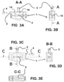
FIG. 3A depicts a sectional view of line A-A ofFIG. 3B -
FIG. 3B depicts a side view of the reactor in one embodiment -
FIG. 3C depicts a front view of the reactor in one embodiment -
FIG. 3D depicts a sectional view of line B-B ofFIG. 3C -
FIG. 3E depicts a sectional view of line C-C ofFIG. 3C -
FIG. 4 depicts a perspective view of aprior art reactor 12 withflanges 11 havingflange mounting holes 13. -
FIG. 5A depicts a frontal view ofreactor 1A of an alternative embodiment of the invention. -
FIG. 5B depicts a side view ofreactor 1A of an alternative embodiment of the invention. -
FIG. 5C depicts a perspective view ofreactor 1A of an alternative embodiment of the invention. - The table below lists the reference numerals employed in the figures, and identifies the element designated by each numeral.
- 1
- reactor 1
- 2.
-
lamp 2 a.k.a "light source", "radiation source" - 3
- port 3
- 4
- ancillary device 4 a.k.a. UV sensor, or wiper.
- 5
-
pipe 5 - 6
-
pipe flange 6 - 7
- pipe flange mounting holes 7
- 8
- pipe flange mounting bolts 8
- 9
- piping
system 9 comprisingpipe 5 havingpipe flange 6, pipe flange mounting holes 7, and pipe flange mounting bolts 8. - 10
- reactor mounting holes 10
- 11
- flange (PRIOR ART) 11
- 12
- reactor (PRIOR ART) 12
- 13
- flange mounting holes (PRIOR ART) 13
- 14
-
inner reactor wall 14 - 15
- lamp
maintenance access port 15 of reactor 1 - 16
-
irradiation cavity 16 - 17
-
second reactor 17 - 1A
-
reactor 1A in an alternative embodiment - 2A
-
lamps 2A in an alternative embodiment - 10A
-
reactor mounting holes 10A in an alternative embodiment - 14A
-
inner reactor wall 14A in an alternative embodiment - 16A
-
irradiation cavity 16A in an alternative embodiment - 18A
-
lamp installation ports 18A in an alternative embodiment - In one embodiment of the present invention, reactor 1 has, reactor mounting holes 10 adapted to be align-able (i.e. coaxial) with mounting holes 7 of a piping flange, substantially
tubular irradiation cavity 16 having a longitudinal axis that is parallel to reactor mounting holes 10 and radiation source 2 (a.k.a "light source", "radiation source". e.g. a mercury vapor UV lamp) that is removably disposed withinirradiation cavity 16; whereby the reactor can be removably secured between theflanges 6 of existing piping system 9 (e.g.FIG. 1A ). - In one embodiment of the present invention, first and
second reactors 1, 17 each have a plurality of mounting holes 10 adapted to be align-able with pipe flange mounting holes 7, substantiallytubular irradiation cavity 16 having a longitudinal axis that is parallel to the plurality of mounting holes 10, andradiation source 2 that is removably disposed withinirradiation cavity 16; whereby first andsecond reactors 1, 17 can be removably secured to each other, betweenflanges 6 of existingpiping system 9, so that the irradiation cavities of the first and second reactors have a substantially common longitudinal axis; whereby the first and second reactors can be selectively arranged, relative to each other, in a plurality of positions around the substantially common longitudinal axis. In other words, the reactors can be rotated with respect to each other. This achieves at least one advantage of allowing greater flexibility to arrange lamps in various positions to alter the fluid irradiation profile. - In one embodiment,
radiation source 2 is elongated (e.g. a mercury vapor UV lamp) and has a longitudinal axis that is perpendicular to the longitudinal axis ofirradiation cavity 16. -
FIG. 1A depicts a perspective view of a single reactor 1 retrofitted intopiping system 9 in accordance with one embodiment of the invention. Pipe flange mounting bolts 8 are inserted through reactor mounting holes 10 and pipe flange mounting holes 7. Reactor mounting holes 10 are coaxial with some of pipe flange mounting holes 7. Thus, reactor 1 can be rotated with respect topiping system 9 in multiple angles according to the location of pipe flange mounting holes 7. -
FIG. 1B depicts a perspective view ofmultiple reactors 1, 17 retrofitted intopiping system 9 in accordance with one embodiment of the invention. It is to be understood that multiple reactors can be placed adjacent to each other at various angles with respect to each other and held in place by pipe flange mounting bolts 8 in conjunction withpipe flanges 6. -
Reactors 1, 17 can be made of the same types of materials commonly used in conventional UV water treatment reactors, or alternatively can be made of other materials having similar strength and structural characteristics, and can be manufactured by casting or machining. The various possible manufacturing options allow for greater cost advantages to be achieved. - Fluid flows in a direction parallel to the longitudinal axis of
irradiation cavity 16. In one embodiment,irradiation cavity 16 is substantially tubular. It is to be understood that such a structure facilitates efficient fluid flow characteristics in accordance with known fluid dynamics, and that other shaped cavities (e.g. ovoid) may be used in keeping with the spirit of the invention. -
Radiation source 2 is removably disposed withinirradiation cavity 16. In one embodiment (FIG. 3B ), lampmaintenance access port 15 is removable to allow replacement and/or maintenance oflamp 2. - It is to be understood that the present invention can be adapted to fit different sized piping systems. In one embodiment (e.g.
FIGS 3A ― 3E),inner reactor wall 14 has a 4 inch diameter and asingle lamp 2. However, other embodiments are possible. E.g. a 30 inch diameter and 10 lamps. - Reactor mounting holes 10 preferably extend entirely through reactor 1 to allow pipe flange mounting bolts 8 to engage pipe flange mounting holes 7 on both sides of reactor 1, or alternatively, a plurality of cascaded reactors.
- In one embodiment (e.g.
FIG. 1B ), mounting bolts 8 are of sufficient length so as to be inserted through the coaxial reactor mounting holes 10 and pipe flange mounting holes 7.FIG. 1B depicts two reactors cascaded, but it is to be understood that more than two reactors can be cascaded. Those of skill in the art will appreciate that mounting bolts 8 would have to be sized accordingly. - In one embodiment, first and
second reactors 1, 17 are of the type depicted inFIGS. 3A - 3E . The irradiation cavities of the first and second reactors have a substantially common longitudinal axis that facilitates fluid (e.g. water) flow from pipingsystem 9 through each of the reactors. - It is to be understood that ports 3 can be utilized for various purposes. E.g. in conjunction with an ancillary device 4 such as a UV sensor or wiper.
- It is to be understood that various sizes of reactor 1 are possible. For example, in one embodiment (
FIGS. 5A-5C ),inner reactor wall 14A has a diameter of either 30 or 32 inches. Twelvelamps 2A are removably secured inlamp installation ports 18A.Reactor 1A is fabricated (i.e. not. cast). Such an embodiment achieves significant space savings over conventional systems.
Claims (2)
- A wafer design UV reactor configured for mounting between flanges of a piping system, which reactor has no flanges and when mounted between flanges of the piping system, presents a substantially tubular irradiation cavity having a longitudinal axis, wherein the reactor comprises a plurality of mounting holes adapted to be align-able coaxially with the mounting holes of a piping flange and a radiation source which is removably disposed within the tubular irradiation cavity, wherein the radiation source longitudinal axis is perpendicular to the longitudinal axis of the tubular irradiation cavity and wherein the reactor is removably securable between the flanges of the piping system whereby the reactor is relocatable in multiple angles according to the location of the pipe flange mounting holes.
- A wafer design UV multiple reactor cascaded system configured for mounting between flanges of a piping system and comprising a first reactor according to claim 1 and at least a second reactor according to claim 1, whereby the first and second reactors can be removably secured to each other, between the flanges of an existing piping system, wherein the irradiation cavities of the first and second reactors have a substantially common longitudinal axis; further whereby the first and second reactors can be selectively arranged, relative to each other, in a plurality of positions around the substantially common longitudinal axis.
Applications Claiming Priority (3)
| Application Number | Priority Date | Filing Date | Title |
|---|---|---|---|
| US201361916155P | 2013-12-14 | 2013-12-14 | |
| EP14838920.8A EP3080049A1 (en) | 2013-12-14 | 2014-12-13 | Wafer design uv reactor |
| PCT/IB2014/002988 WO2015087161A1 (en) | 2013-12-14 | 2014-12-13 | Wafer design uv reactor |
Related Parent Applications (2)
| Application Number | Title | Priority Date | Filing Date |
|---|---|---|---|
| EP14838920.8A Division EP3080049A1 (en) | 2013-12-14 | 2014-12-13 | Wafer design uv reactor |
| PCT/IB2014/002988 Previously-Filed-Application WO2015087161A1 (en) | 2013-12-14 | 2014-12-13 | Wafer design uv reactor |
Publications (3)
| Publication Number | Publication Date |
|---|---|
| EP3960712A1 true EP3960712A1 (en) | 2022-03-02 |
| EP3960712B1 EP3960712B1 (en) | 2024-12-04 |
| EP3960712C0 EP3960712C0 (en) | 2024-12-04 |
Family
ID=52589701
Family Applications (2)
| Application Number | Title | Priority Date | Filing Date |
|---|---|---|---|
| EP21170008.3A Active EP3960712B1 (en) | 2013-12-14 | 2014-12-13 | Uv reactor |
| EP14838920.8A Ceased EP3080049A1 (en) | 2013-12-14 | 2014-12-13 | Wafer design uv reactor |
Family Applications After (1)
| Application Number | Title | Priority Date | Filing Date |
|---|---|---|---|
| EP14838920.8A Ceased EP3080049A1 (en) | 2013-12-14 | 2014-12-13 | Wafer design uv reactor |
Country Status (3)
| Country | Link |
|---|---|
| US (1) | US20160272510A1 (en) |
| EP (2) | EP3960712B1 (en) |
| WO (1) | WO2015087161A1 (en) |
Citations (5)
| Publication number | Priority date | Publication date | Assignee | Title |
|---|---|---|---|---|
| WO2004033375A1 (en) * | 2002-10-09 | 2004-04-22 | Trojan Technologies Inc. | Ultraviolet fluid treatment system |
| FR2880014A1 (en) * | 2004-12-27 | 2006-06-30 | Andre Tourasse | Water treatment unit for reducing chloramines in public swimming pool water comprises modules fitted with germicidal lamps and/or mechanical cleaning system |
| US20100258508A1 (en) * | 2006-11-14 | 2010-10-14 | Uri Levy | Method and apparatus for liquid disinfection using light transparent conduit |
| EP2368852A1 (en) * | 2010-03-15 | 2011-09-28 | Kabushiki Kaisha Toshiba | Ultraviolet water treatment apparatus |
| US20130062532A1 (en) * | 2011-09-14 | 2013-03-14 | Kabushiki Kaisha Toshiba | Ultraviolet irradiation apparatus |
-
2014
- 2014-12-13 WO PCT/IB2014/002988 patent/WO2015087161A1/en not_active Ceased
- 2014-12-13 EP EP21170008.3A patent/EP3960712B1/en active Active
- 2014-12-13 EP EP14838920.8A patent/EP3080049A1/en not_active Ceased
- 2014-12-13 US US14/425,019 patent/US20160272510A1/en not_active Abandoned
Patent Citations (5)
| Publication number | Priority date | Publication date | Assignee | Title |
|---|---|---|---|---|
| WO2004033375A1 (en) * | 2002-10-09 | 2004-04-22 | Trojan Technologies Inc. | Ultraviolet fluid treatment system |
| FR2880014A1 (en) * | 2004-12-27 | 2006-06-30 | Andre Tourasse | Water treatment unit for reducing chloramines in public swimming pool water comprises modules fitted with germicidal lamps and/or mechanical cleaning system |
| US20100258508A1 (en) * | 2006-11-14 | 2010-10-14 | Uri Levy | Method and apparatus for liquid disinfection using light transparent conduit |
| EP2368852A1 (en) * | 2010-03-15 | 2011-09-28 | Kabushiki Kaisha Toshiba | Ultraviolet water treatment apparatus |
| US20130062532A1 (en) * | 2011-09-14 | 2013-03-14 | Kabushiki Kaisha Toshiba | Ultraviolet irradiation apparatus |
Also Published As
| Publication number | Publication date |
|---|---|
| WO2015087161A1 (en) | 2015-06-18 |
| EP3080049A1 (en) | 2016-10-19 |
| EP3960712B1 (en) | 2024-12-04 |
| US20160272510A1 (en) | 2016-09-22 |
| EP3960712C0 (en) | 2024-12-04 |
Similar Documents
| Publication | Publication Date | Title |
|---|---|---|
| CA2823458C (en) | Adjustable bracket assembly for an ultraviolet lamp | |
| EP3209912B1 (en) | Improved valve | |
| KR102166626B1 (en) | Condensate removal device | |
| JP6189914B2 (en) | Ultraviolet irradiation module cell, ultraviolet irradiation module, and installation method of ultraviolet irradiation module | |
| US8887319B2 (en) | Adjustable fixture support carrier for off-the-floor plumbing fixtures | |
| AR098584A1 (en) | PLASMA REACTOR FOR THE CONDITIONING OF A HYDROCARBON FLUID | |
| KR20120053025A (en) | Ultraviolet reactor comprising baffle plates | |
| CN102458673B (en) | Air inductor | |
| CN108136056A (en) | Radiation treatment system and method | |
| ES2923852T3 (en) | Holding device for a laser device | |
| RU2014141368A (en) | RIGHT STRAIGHT FLOW SEAT RING AND REGULATING VALVE WITH RECTIFIED STRAIGHT SEAT RING | |
| ES2464818T3 (en) | Valve insert for sanitary fittings | |
| PE20180748A1 (en) | PLASMA INJECTION SYSTEM, AIR FILTRATION AND DISINFECTION | |
| EP3960712B1 (en) | Uv reactor | |
| ES2684439T3 (en) | Device and process for distributing a fluid | |
| ES2779926T3 (en) | Device for mounting a connection element, in order to connect a pipeline through a partition | |
| KR102150372B1 (en) | Pressure stabilization device using double porous plates | |
| BR112015018809B1 (en) | UV LAMP MODULE HAVING ONE STRUCTURE AND AT LEAST TWO LAMP UNITS | |
| ITPD20090131A1 (en) | FUME DISCHARGE DEVICE FOR BOILERS | |
| CN101033090B (en) | Ultraviolet sterilizer with water port equipped at two ends of disinfection cavity | |
| KR100955798B1 (en) | Cavitation check for sluice valve | |
| WO2007050307A3 (en) | Sputtering target and means for cooling the target | |
| KR200211515Y1 (en) | Improvements in filter for use in fluid pipe | |
| KR200473129Y1 (en) | Solenoid valve | |
| KR20130004571U (en) | Fitting for Pipe to prevent Flow Leakage at Pipe Line |
Legal Events
| Date | Code | Title | Description |
|---|---|---|---|
| PUAI | Public reference made under article 153(3) epc to a published international application that has entered the european phase |
Free format text: ORIGINAL CODE: 0009012 |
|
| STAA | Information on the status of an ep patent application or granted ep patent |
Free format text: STATUS: THE APPLICATION HAS BEEN PUBLISHED |
|
| AC | Divisional application: reference to earlier application |
Ref document number: 3080049 Country of ref document: EP Kind code of ref document: P |
|
| AK | Designated contracting states |
Kind code of ref document: A1 Designated state(s): AL AT BE BG CH CY CZ DE DK EE ES FI FR GB GR HR HU IE IS IT LI LT LU LV MC MK MT NL NO PL PT RO RS SE SI SK SM TR |
|
| RAP1 | Party data changed (applicant data changed or rights of an application transferred) |
Owner name: EVOQUA WATER TECHNOLOGIES LIMITED |
|
| STAA | Information on the status of an ep patent application or granted ep patent |
Free format text: STATUS: REQUEST FOR EXAMINATION WAS MADE |
|
| 17P | Request for examination filed |
Effective date: 20220902 |
|
| RBV | Designated contracting states (corrected) |
Designated state(s): AL AT BE BG CH CY CZ DE DK EE ES FI FR GB GR HR HU IE IS IT LI LT LU LV MC MK MT NL NO PL PT RO RS SE SI SK SM TR |
|
| GRAP | Despatch of communication of intention to grant a patent |
Free format text: ORIGINAL CODE: EPIDOSNIGR1 |
|
| STAA | Information on the status of an ep patent application or granted ep patent |
Free format text: STATUS: GRANT OF PATENT IS INTENDED |
|
| INTG | Intention to grant announced |
Effective date: 20240711 |
|
| RAP3 | Party data changed (applicant data changed or rights of an application transferred) |
Owner name: EVOQUA WATER TECHNOLOGIES LIMITED |
|
| GRAS | Grant fee paid |
Free format text: ORIGINAL CODE: EPIDOSNIGR3 |
|
| GRAA | (expected) grant |
Free format text: ORIGINAL CODE: 0009210 |
|
| STAA | Information on the status of an ep patent application or granted ep patent |
Free format text: STATUS: THE PATENT HAS BEEN GRANTED |
|
| AC | Divisional application: reference to earlier application |
Ref document number: 3080049 Country of ref document: EP Kind code of ref document: P |
|
| AK | Designated contracting states |
Kind code of ref document: B1 Designated state(s): AL AT BE BG CH CY CZ DE DK EE ES FI FR GB GR HR HU IE IS IT LI LT LU LV MC MK MT NL NO PL PT RO RS SE SI SK SM TR |
|
| REG | Reference to a national code |
Ref country code: CH Ref legal event code: EP |
|
| REG | Reference to a national code |
Ref country code: DE Ref legal event code: R096 Ref document number: 602014091305 Country of ref document: DE |
|
| REG | Reference to a national code |
Ref country code: IE Ref legal event code: FG4D |
|
| U01 | Request for unitary effect filed |
Effective date: 20241223 |
|
| U07 | Unitary effect registered |
Designated state(s): AT BE BG DE DK EE FI FR IT LT LU LV MT NL PT RO SE SI Effective date: 20250114 |
|
| PG25 | Lapsed in a contracting state [announced via postgrant information from national office to epo] |
Ref country code: HR Free format text: LAPSE BECAUSE OF FAILURE TO SUBMIT A TRANSLATION OF THE DESCRIPTION OR TO PAY THE FEE WITHIN THE PRESCRIBED TIME-LIMIT Effective date: 20241204 |
|
| PG25 | Lapsed in a contracting state [announced via postgrant information from national office to epo] |
Ref country code: ES Free format text: LAPSE BECAUSE OF FAILURE TO SUBMIT A TRANSLATION OF THE DESCRIPTION OR TO PAY THE FEE WITHIN THE PRESCRIBED TIME-LIMIT Effective date: 20241204 |
|
| PG25 | Lapsed in a contracting state [announced via postgrant information from national office to epo] |
Ref country code: NO Free format text: LAPSE BECAUSE OF FAILURE TO SUBMIT A TRANSLATION OF THE DESCRIPTION OR TO PAY THE FEE WITHIN THE PRESCRIBED TIME-LIMIT Effective date: 20250304 |
|
| PG25 | Lapsed in a contracting state [announced via postgrant information from national office to epo] |
Ref country code: GR Free format text: LAPSE BECAUSE OF FAILURE TO SUBMIT A TRANSLATION OF THE DESCRIPTION OR TO PAY THE FEE WITHIN THE PRESCRIBED TIME-LIMIT Effective date: 20250305 |
|
| PG25 | Lapsed in a contracting state [announced via postgrant information from national office to epo] |
Ref country code: RS Free format text: LAPSE BECAUSE OF FAILURE TO SUBMIT A TRANSLATION OF THE DESCRIPTION OR TO PAY THE FEE WITHIN THE PRESCRIBED TIME-LIMIT Effective date: 20250304 |
|
| PG25 | Lapsed in a contracting state [announced via postgrant information from national office to epo] |
Ref country code: SM Free format text: LAPSE BECAUSE OF FAILURE TO SUBMIT A TRANSLATION OF THE DESCRIPTION OR TO PAY THE FEE WITHIN THE PRESCRIBED TIME-LIMIT Effective date: 20241204 |
|
| PG25 | Lapsed in a contracting state [announced via postgrant information from national office to epo] |
Ref country code: PL Free format text: LAPSE BECAUSE OF FAILURE TO SUBMIT A TRANSLATION OF THE DESCRIPTION OR TO PAY THE FEE WITHIN THE PRESCRIBED TIME-LIMIT Effective date: 20241204 |
|
| PG25 | Lapsed in a contracting state [announced via postgrant information from national office to epo] |
Ref country code: IS Free format text: LAPSE BECAUSE OF FAILURE TO SUBMIT A TRANSLATION OF THE DESCRIPTION OR TO PAY THE FEE WITHIN THE PRESCRIBED TIME-LIMIT Effective date: 20250404 |
|
| PG25 | Lapsed in a contracting state [announced via postgrant information from national office to epo] |
Ref country code: SK Free format text: LAPSE BECAUSE OF FAILURE TO SUBMIT A TRANSLATION OF THE DESCRIPTION OR TO PAY THE FEE WITHIN THE PRESCRIBED TIME-LIMIT Effective date: 20241204 |
|
| PG25 | Lapsed in a contracting state [announced via postgrant information from national office to epo] |
Ref country code: CZ Free format text: LAPSE BECAUSE OF FAILURE TO SUBMIT A TRANSLATION OF THE DESCRIPTION OR TO PAY THE FEE WITHIN THE PRESCRIBED TIME-LIMIT Effective date: 20241204 |
|
| REG | Reference to a national code |
Ref country code: CH Ref legal event code: PL |
|
| U21 | Renewal fee for the european patent with unitary effect paid with additional fee |
Year of fee payment: 11 Effective date: 20250626 |
|
| PG25 | Lapsed in a contracting state [announced via postgrant information from national office to epo] |
Ref country code: MC Free format text: LAPSE BECAUSE OF FAILURE TO SUBMIT A TRANSLATION OF THE DESCRIPTION OR TO PAY THE FEE WITHIN THE PRESCRIBED TIME-LIMIT Effective date: 20241204 |
|
| PLBE | No opposition filed within time limit |
Free format text: ORIGINAL CODE: 0009261 |
|
| STAA | Information on the status of an ep patent application or granted ep patent |
Free format text: STATUS: NO OPPOSITION FILED WITHIN TIME LIMIT |
|
| PG25 | Lapsed in a contracting state [announced via postgrant information from national office to epo] |
Ref country code: CH Free format text: LAPSE BECAUSE OF NON-PAYMENT OF DUE FEES Effective date: 20241231 |
|
| PG25 | Lapsed in a contracting state [announced via postgrant information from national office to epo] |
Ref country code: IE Free format text: LAPSE BECAUSE OF NON-PAYMENT OF DUE FEES Effective date: 20241213 |
|
| 26N | No opposition filed |
Effective date: 20250905 |
|
| U20 | Renewal fee for the european patent with unitary effect paid |
Year of fee payment: 12 Effective date: 20251119 |
|
| PGFP | Annual fee paid to national office [announced via postgrant information from national office to epo] |
Ref country code: GB Payment date: 20251121 Year of fee payment: 12 |
|
| PG25 | Lapsed in a contracting state [announced via postgrant information from national office to epo] |
Ref country code: CY Free format text: LAPSE BECAUSE OF FAILURE TO SUBMIT A TRANSLATION OF THE DESCRIPTION OR TO PAY THE FEE WITHIN THE PRESCRIBED TIME-LIMIT Effective date: 20241204 |
|
| PG25 | Lapsed in a contracting state [announced via postgrant information from national office to epo] |
Ref country code: TR Free format text: LAPSE BECAUSE OF FAILURE TO SUBMIT A TRANSLATION OF THE DESCRIPTION OR TO PAY THE FEE WITHIN THE PRESCRIBED TIME-LIMIT Effective date: 20241204 |
|
| PG25 | Lapsed in a contracting state [announced via postgrant information from national office to epo] |
Ref country code: HU Free format text: LAPSE BECAUSE OF FAILURE TO SUBMIT A TRANSLATION OF THE DESCRIPTION OR TO PAY THE FEE WITHIN THE PRESCRIBED TIME-LIMIT; INVALID AB INITIO Effective date: 20141213 |