EP3960435A2 - Method and apparatus for forming an apex - Google Patents
Method and apparatus for forming an apex Download PDFInfo
- Publication number
- EP3960435A2 EP3960435A2 EP21194149.7A EP21194149A EP3960435A2 EP 3960435 A2 EP3960435 A2 EP 3960435A2 EP 21194149 A EP21194149 A EP 21194149A EP 3960435 A2 EP3960435 A2 EP 3960435A2
- Authority
- EP
- European Patent Office
- Prior art keywords
- rotatable platen
- rotatable
- platen
- bars
- apex
- Prior art date
- Legal status (The legal status is an assumption and is not a legal conclusion. Google has not performed a legal analysis and makes no representation as to the accuracy of the status listed.)
- Granted
Links
Images
Classifications
-
- B—PERFORMING OPERATIONS; TRANSPORTING
- B29—WORKING OF PLASTICS; WORKING OF SUBSTANCES IN A PLASTIC STATE IN GENERAL
- B29D—PRODUCING PARTICULAR ARTICLES FROM PLASTICS OR FROM SUBSTANCES IN A PLASTIC STATE
- B29D30/00—Producing pneumatic or solid tyres or parts thereof
- B29D30/06—Pneumatic tyres or parts thereof (e.g. produced by casting, moulding, compression moulding, injection moulding, centrifugal casting)
- B29D30/08—Building tyres
- B29D30/20—Building tyres by the flat-tyre method, i.e. building on cylindrical drums
- B29D30/30—Applying the layers; Guiding or stretching the layers during application
- B29D30/3007—Applying the layers; Guiding or stretching the layers during application by feeding a sheet perpendicular to the drum axis and joining the ends to form an annular element
-
- B—PERFORMING OPERATIONS; TRANSPORTING
- B29—WORKING OF PLASTICS; WORKING OF SUBSTANCES IN A PLASTIC STATE IN GENERAL
- B29D—PRODUCING PARTICULAR ARTICLES FROM PLASTICS OR FROM SUBSTANCES IN A PLASTIC STATE
- B29D30/00—Producing pneumatic or solid tyres or parts thereof
- B29D30/06—Pneumatic tyres or parts thereof (e.g. produced by casting, moulding, compression moulding, injection moulding, centrifugal casting)
- B29D30/48—Bead-rings or bead-cores; Treatment thereof prior to building the tyre
-
- B—PERFORMING OPERATIONS; TRANSPORTING
- B29—WORKING OF PLASTICS; WORKING OF SUBSTANCES IN A PLASTIC STATE IN GENERAL
- B29C—SHAPING OR JOINING OF PLASTICS; SHAPING OF MATERIAL IN A PLASTIC STATE, NOT OTHERWISE PROVIDED FOR; AFTER-TREATMENT OF THE SHAPED PRODUCTS, e.g. REPAIRING
- B29C33/00—Moulds or cores; Details thereof or accessories therefor
- B29C33/56—Coatings, e.g. enameled or galvanised; Releasing, lubricating or separating agents
- B29C33/60—Releasing, lubricating or separating agents
-
- B—PERFORMING OPERATIONS; TRANSPORTING
- B29—WORKING OF PLASTICS; WORKING OF SUBSTANCES IN A PLASTIC STATE IN GENERAL
- B29D—PRODUCING PARTICULAR ARTICLES FROM PLASTICS OR FROM SUBSTANCES IN A PLASTIC STATE
- B29D30/00—Producing pneumatic or solid tyres or parts thereof
- B29D30/06—Pneumatic tyres or parts thereof (e.g. produced by casting, moulding, compression moulding, injection moulding, centrifugal casting)
- B29D30/52—Unvulcanised treads, e.g. on used tyres; Retreading
- B29D30/58—Applying bands of rubber treads, i.e. applying camel backs
- B29D30/62—Applying bands of rubber treads, i.e. applying camel backs by extrusion or injection of the tread on carcass
-
- B—PERFORMING OPERATIONS; TRANSPORTING
- B29—WORKING OF PLASTICS; WORKING OF SUBSTANCES IN A PLASTIC STATE IN GENERAL
- B29D—PRODUCING PARTICULAR ARTICLES FROM PLASTICS OR FROM SUBSTANCES IN A PLASTIC STATE
- B29D30/00—Producing pneumatic or solid tyres or parts thereof
- B29D30/06—Pneumatic tyres or parts thereof (e.g. produced by casting, moulding, compression moulding, injection moulding, centrifugal casting)
- B29D30/48—Bead-rings or bead-cores; Treatment thereof prior to building the tyre
- B29D2030/481—Fillers or apexes
-
- B—PERFORMING OPERATIONS; TRANSPORTING
- B29—WORKING OF PLASTICS; WORKING OF SUBSTANCES IN A PLASTIC STATE IN GENERAL
- B29D—PRODUCING PARTICULAR ARTICLES FROM PLASTICS OR FROM SUBSTANCES IN A PLASTIC STATE
- B29D30/00—Producing pneumatic or solid tyres or parts thereof
- B29D30/06—Pneumatic tyres or parts thereof (e.g. produced by casting, moulding, compression moulding, injection moulding, centrifugal casting)
- B29D30/48—Bead-rings or bead-cores; Treatment thereof prior to building the tyre
- B29D2030/482—Applying fillers or apexes to bead cores
-
- B—PERFORMING OPERATIONS; TRANSPORTING
- B29—WORKING OF PLASTICS; WORKING OF SUBSTANCES IN A PLASTIC STATE IN GENERAL
- B29D—PRODUCING PARTICULAR ARTICLES FROM PLASTICS OR FROM SUBSTANCES IN A PLASTIC STATE
- B29D30/00—Producing pneumatic or solid tyres or parts thereof
- B29D30/06—Pneumatic tyres or parts thereof (e.g. produced by casting, moulding, compression moulding, injection moulding, centrifugal casting)
- B29D30/48—Bead-rings or bead-cores; Treatment thereof prior to building the tyre
- B29D2030/486—Additional components for the tyre bead areas, e.g. cushioning elements, chafers, flippers
-
- B—PERFORMING OPERATIONS; TRANSPORTING
- B29—WORKING OF PLASTICS; WORKING OF SUBSTANCES IN A PLASTIC STATE IN GENERAL
- B29D—PRODUCING PARTICULAR ARTICLES FROM PLASTICS OR FROM SUBSTANCES IN A PLASTIC STATE
- B29D30/00—Producing pneumatic or solid tyres or parts thereof
- B29D30/06—Pneumatic tyres or parts thereof (e.g. produced by casting, moulding, compression moulding, injection moulding, centrifugal casting)
- B29D30/48—Bead-rings or bead-cores; Treatment thereof prior to building the tyre
- B29D2030/487—Forming devices for manufacturing the beads
Definitions
- the invention relates in general to tire manufacturing, and more particularly to a method and apparatus for forming an improved apex for a pneumatic tire.
- a conventional radial-ply automobile tire includes radial plies that are wrapped around two annular inextensible beads. The portions of the plies that extend beyond the beads are turned up around the beads, forming "turn-ups.” An annular rubber filler bounded by the turned-up ply and the bead is called an "apex.”
- the choice of dimensions and material properties of the apex affects the performance of the tire, such as tire weight, sidewall stiffness, handling, ride comfort, flexural heat, material fatigue, and tire life. It is desired to form the apex such that is does not have a splice in order to improve tire uniformity and consistency. It is also desirable to form an apex that has a tip that does not curl. It is also desired to have an improved method and apparatus for making an apex that does not cause the apex to be damaged when removed from the platen.
- the invention relates to a method in accordance with claim 1 and to an apparatus in accordance with claim 8.
- Axial and “axially” means the lines or directions that are parallel to the axis of rotation of the tire.
- “Circumferential” means lines or directions extending along the perimeter of the surface of the annular tread perpendicular to the axial direction; it can also refer to the direction of the sets of adjacent circular curves whose radii define the axial curvature of the tread as viewed in cross section.
- Ring and radially mean directions radially toward or away from the axis of rotation of the tire.
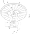
- FIGS. 1-5 illustrates an apex forming apparatus 100 of the present invention.
- the apex forming apparatus 100 includes an annular flat platen 110 that is rotatably mounted and is preferably oriented in the vertical direction (Z). However, the annular flat platen 110 may also be oriented in the horizontal direction or other desired orientation.
- an optional radially expandable bead chuck 115 for receiving a bead.
- the bead chuck is formed of three or more members that are arranged in a circle for receiving the bead. As shown in FIG.
- the annular flat platen 110 is retractable in the axial (X) direction away from the bead chuck to facilitate removal of the formed apex A or apex and bead assembly. While the bead chuck holds the bead in place, the annular flat platen provides a rotatable and removable support for applying a continuous strip of rubber that is formed into an apex or a combination bead and apex subassembly.
- the annular flat platen 110 preferably has a nonstick coating.
- the annular platen 110 further comprises one or more radially oriented bars 120.
- the one or more radially oriented bars 120 are mounted on the outer surface of the platen and are preferably coated with the nonstick coating.
- the annular flat platen 110 further includes at least one or more standoff bars 130 that are preferably oriented in the radial direction. When the platen is mounted in a first position for applying the apex, the radially oriented standoff bars are mounted flush with the surface of the annular platen such as shown in FIG. 1 .
- the annular flat platen 110 is retracted in an axial direction away from the bead support 115.
- the one or more standoff bars 130 remain in position as shown in FIG. 5 . The movement of the platen away from the standoff bars 130 breaks the surface adhesion of the rubber apex, thus facilitating the removal of the apex from the outer surface of the annular flat platen 110.
- FIG. 1 further illustrates a strip forming apparatus which may utilize an optional extruder 12 in cooperation with an optional gear pump 14 to form a strip of rubber.
- the rubber composition is pumped through the extruder and optional gear pump into a nozzle 70.
- the nozzle 70 is mounted on a rotatable head 90, which allows the rotatable head 90 and nozzle 70 to rotate about the Z-axis.
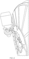
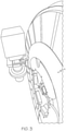
- the nozzle has a small tapered tip. As best shown in FIGS. 2 and 3 , this rotation is beneficial for forming the apex, as the rotatable head 90 and nozzle 70 allows the rubber to penetrate the tight intersection of the bead and platen interface, so that the rubber forming the apex penetrates the bead for good adhesion.
- a pneumatically driven stitching wheel Located adjacent the output of the nozzle 70 is a pneumatically driven stitching wheel, which facilitates application of the strip to the platen 110.
- the stitching pressure is pneumatically controlled.
- the nozzle 70 is also used to shape the strip of the rubber into a desired geometry.
Landscapes
- Engineering & Computer Science (AREA)
- Mechanical Engineering (AREA)
- Tyre Moulding (AREA)
Abstract
Description
- The invention relates in general to tire manufacturing, and more particularly to a method and apparatus for forming an improved apex for a pneumatic tire.
- A conventional radial-ply automobile tire includes radial plies that are wrapped around two annular inextensible beads. The portions of the plies that extend beyond the beads are turned up around the beads, forming "turn-ups." An annular rubber filler bounded by the turned-up ply and the bead is called an "apex." The choice of dimensions and material properties of the apex affects the performance of the tire, such as tire weight, sidewall stiffness, handling, ride comfort, flexural heat, material fatigue, and tire life. It is desired to form the apex such that is does not have a splice in order to improve tire uniformity and consistency. It is also desirable to form an apex that has a tip that does not curl. It is also desired to have an improved method and apparatus for making an apex that does not cause the apex to be damaged when removed from the platen.
- The invention relates to a method in accordance with claim 1 and to an apparatus in accordance with claim 8.
- Dependent claims refer to preferred embodiments of the invention.
- "Axial" and "axially" means the lines or directions that are parallel to the axis of rotation of the tire.
- "Circumferential" means lines or directions extending along the perimeter of the surface of the annular tread perpendicular to the axial direction; it can also refer to the direction of the sets of adjacent circular curves whose radii define the axial curvature of the tread as viewed in cross section.
- "Radial" and "radially" mean directions radially toward or away from the axis of rotation of the tire.
- The invention will be described by way of example and with reference to the accompanying drawings in which:
-
FIG. 1 illustrates a perspective view of an apex forming apparatus which includes a rotatable platen and an extruder apparatus with a pivotable head; -
FIG. 2 illustrates a close-up perspective view of a bead mounted in the chuck of the apex forming apparatus; -
FIG. 3 illustrates an apex being formed on the bead and the rotatable platen by the nozzle of the extruder apparatus; -
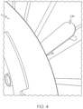
FIG. 4 illustrates the extension of a radial bar from the outer surface of the platen to facilitate removal of the apex from the platen; and -
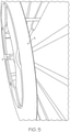
FIG. 5 illustrates the axial retraction of the rotatable platen from the bead chuck to facilitate removal of the apex from the platen. -
FIGS. 1-5 illustrates anapex forming apparatus 100 of the present invention. Theapex forming apparatus 100 includes an annularflat platen 110 that is rotatably mounted and is preferably oriented in the vertical direction (Z). However, the annularflat platen 110 may also be oriented in the horizontal direction or other desired orientation. Located at the radially inner portion of the annularflat platen 110 is an optional radiallyexpandable bead chuck 115 for receiving a bead. The bead chuck is formed of three or more members that are arranged in a circle for receiving the bead. As shown inFIG. 5 , the annularflat platen 110 is retractable in the axial (X) direction away from the bead chuck to facilitate removal of the formed apex A or apex and bead assembly. While the bead chuck holds the bead in place, the annular flat platen provides a rotatable and removable support for applying a continuous strip of rubber that is formed into an apex or a combination bead and apex subassembly. - The annular
flat platen 110 preferably has a nonstick coating. Theannular platen 110 further comprises one or more radiallyoriented bars 120. The one or more radially orientedbars 120 are mounted on the outer surface of the platen and are preferably coated with the nonstick coating. The annularflat platen 110 further includes at least one ormore standoff bars 130 that are preferably oriented in the radial direction. When the platen is mounted in a first position for applying the apex, the radially oriented standoff bars are mounted flush with the surface of the annular platen such as shown inFIG. 1 . After the apex has been applied to the bead and annular flat platen and it is time for removal, the annularflat platen 110 is retracted in an axial direction away from thebead support 115. When the annular flat platen retracts, the one ormore standoff bars 130 remain in position as shown inFIG. 5 . The movement of the platen away from thestandoff bars 130 breaks the surface adhesion of the rubber apex, thus facilitating the removal of the apex from the outer surface of the annularflat platen 110. -
FIG. 1 further illustrates a strip forming apparatus which may utilize anoptional extruder 12 in cooperation with anoptional gear pump 14 to form a strip of rubber. The rubber composition is pumped through the extruder and optional gear pump into anozzle 70. Thenozzle 70 is mounted on arotatable head 90, which allows therotatable head 90 andnozzle 70 to rotate about the Z-axis. The nozzle has a small tapered tip. As best shown inFIGS. 2 and3 , this rotation is beneficial for forming the apex, as therotatable head 90 andnozzle 70 allows the rubber to penetrate the tight intersection of the bead and platen interface, so that the rubber forming the apex penetrates the bead for good adhesion. Located adjacent the output of thenozzle 70 is a pneumatically driven stitching wheel, which facilitates application of the strip to theplaten 110. The stitching pressure is pneumatically controlled. Thenozzle 70 is also used to shape the strip of the rubber into a desired geometry.
Claims (15)
- A method for forming an apex, the method comprising the steps of: winding an elastomer strip of rubber onto a rotatable platen (110), wherein the rotatable platen has a radially expandable bead chuck (115) located on a radially inner portion of the rotatable platen (110), wherein the rotatable platen (110) has an outer surface having a nonstick coating, and wherein the rotatable platen further includes one or more bars (120).
- The method of claim 1 wherein a bead is mounted and secured on the expandable bead chuck (115), and the elastomer strip of rubber is wound on the bead.
- The method of claim 1 or 2 wherein the one or more bars (120) are oriented in the radial direction and/or wherein the rotatable platen (110) is oriented in the vertical (Z) direction.
- The method of at least one of the previous claims wherein a standoff bar (130) is positioned so that it is flush on the rotatable platen (110) and wherein the standoff bar (130) remains in position when the rotatable platen (110) is retracted.
- The method of claim 4 wherein the standoff bar (130) breaks the adhesion of the formed apex from the outer surface of the rotatable platen (110) when the rotatable platen is retracted.
- The method of at least one of the previous claims wherein the strip is applied using a rotatable head (90) which is rotatable about the vertical (Z) direction.
- The method of at least one of the previous claims wherein the strip is applied using a nozzle (70) mounted on a rotatable head (90) which is rotatable about the vertical (Z) direction, and, optionally, wherein a rotatable stitcher roll is positioned under the nozzle (70).
- An apparatus for forming an apex and bead subassembly, the apparatus (100) comprising a rotatable platen (110), a radially expandable bead chuck (115) mounted on the rotatable platen (110), wherein the rotatable platen (110) has an outer surface having a nonstick coating, and wherein the outer surface further includes one or more bars (120).
- The apparatus of claim 8 wherein the one or more bars (120) are oriented in the radial direction.
- The apparatus of claim 8 or 9 wherein the one or more bars (120) do not have a nonstick coating.
- The apparatus of claim 8 or 9 wherein the one or more bars (120) have a nonstick coating.
- The apparatus of at least one of the previous claims 12 to 14 wherein the rotatable platen (110) is oriented in the vertical (Z) direction.
- The apparatus of at least one of the previous claims 8 to 12 wherein the rotatable platen (110) is axially retractable from the bead chuck (115) in an axial (X) direction.
- The apparatus of at least one of the previous claims 8 to 13 further including one or more standoff bars (130), wherein the standoff bars (130) are flush with outer surface of the rotatable platen (110) in a first position, and nonflush when the rotatable platen (110) is axially retracted.
- The apparatus of claim 14 wherein there at least four standoff bars.
Applications Claiming Priority (2)
| Application Number | Priority Date | Filing Date | Title |
|---|---|---|---|
| US202063072726P | 2020-08-31 | 2020-08-31 | |
| US17/331,745 US11981101B2 (en) | 2020-08-31 | 2021-05-27 | Method and apparatus for forming an apex |
Publications (3)
| Publication Number | Publication Date |
|---|---|
| EP3960435A2 true EP3960435A2 (en) | 2022-03-02 |
| EP3960435A3 EP3960435A3 (en) | 2022-03-09 |
| EP3960435B1 EP3960435B1 (en) | 2023-07-19 |
Family
ID=77595336
Family Applications (1)
| Application Number | Title | Priority Date | Filing Date |
|---|---|---|---|
| EP21194149.7A Active EP3960435B1 (en) | 2020-08-31 | 2021-08-31 | Method and apparatus for forming an apex |
Country Status (4)
| Country | Link |
|---|---|
| US (1) | US11981101B2 (en) |
| EP (1) | EP3960435B1 (en) |
| CN (1) | CN114103211A (en) |
| BR (1) | BR102021016524A2 (en) |
Family Cites Families (20)
| Publication number | Priority date | Publication date | Assignee | Title |
|---|---|---|---|---|
| US5735995A (en) | 1996-02-13 | 1998-04-07 | The Steelastic Company, L.L.C. | Apparatus for applying an apex filler to a bead ring |
| JP4010611B2 (en) | 1997-10-07 | 2007-11-21 | 株式会社ブリヂストン | Molding method of bead filler |
| JP3634209B2 (en) | 1999-09-30 | 2005-03-30 | 住友ゴム工業株式会社 | Assembly bead core forming device |
| US6623583B2 (en) | 2001-06-05 | 2003-09-23 | The Goodyear Tire And Rubber Company | Bead holder |
| KR100461661B1 (en) | 2002-03-30 | 2004-12-14 | 금호타이어 주식회사 | Automatic flipping device |
| JP4043297B2 (en) * | 2002-06-14 | 2008-02-06 | 横浜ゴム株式会社 | Member peeling device in annular rubber member molding device |
| JP4632650B2 (en) * | 2003-10-07 | 2011-02-16 | 株式会社ブリヂストン | Tire manufacturing method, preset bead molding apparatus and preset bead molding system |
| GB0412573D0 (en) | 2004-06-04 | 2004-07-07 | A R T | Formation of a tire bead assembly |
| US8585845B2 (en) | 2010-11-10 | 2013-11-19 | The Goodyear Tire & Rubber Company | Tire-forming apparatus and related methods |
| JP2013216051A (en) * | 2012-04-11 | 2013-10-24 | Toyo Tire & Rubber Co Ltd | Peeling device, peeling method, and molding device of annular rubber member |
| JP5580849B2 (en) | 2012-05-16 | 2014-08-27 | 住友ゴム工業株式会社 | Bead apex rubber forming method and bead apex rubber forming apparatus used therefor |
| US20130340911A1 (en) * | 2012-06-20 | 2013-12-26 | Erich Nicolaus Lemaire | Bead core-apex subassembly, pneumatic tire therewith and method of manufacturing a bead core-apex subassembly |
| US8955571B2 (en) * | 2012-12-12 | 2015-02-17 | The Goodyear Tire & Rubber Company | Apparatus for supporting and holding a bead core-apex subassembly and method of producing and transporting the bead core-apex subassembly |
| JP2014144552A (en) | 2013-01-28 | 2014-08-14 | Bridgestone Corp | Molding method of preset bead |
| JP5814313B2 (en) | 2013-08-06 | 2015-11-17 | 住友ゴム工業株式会社 | Bead assembly machine |
| NL2013314B1 (en) * | 2014-08-08 | 2016-09-21 | Vmi Holland Bv | Stretching device for an apex filler strip and apex handling system comprising the stretching device. |
| DE102014226174A1 (en) | 2014-12-17 | 2016-06-23 | Continental Reifen Deutschland Gmbh | Device for manufacturing core packages for pneumatic vehicle tires |
| NL2015968B1 (en) * | 2015-12-16 | 2017-06-30 | Vmi Holland Bv | Drum set for manufacturing a bead-apex for a tire and assembly comprising said tooling. |
| CN107139512B (en) | 2017-06-30 | 2023-09-19 | 江苏龙贞智能技术有限公司 | Two-station bead loading and unloading machine |
| CN111497296B (en) | 2020-04-15 | 2022-07-05 | 桂林橡胶设计院有限公司 | Processing method for fitting and forming tire bead |
-
2021
- 2021-05-27 US US17/331,745 patent/US11981101B2/en active Active
- 2021-08-20 BR BR102021016524-3A patent/BR102021016524A2/en not_active IP Right Cessation
- 2021-08-31 EP EP21194149.7A patent/EP3960435B1/en active Active
- 2021-08-31 CN CN202111013760.2A patent/CN114103211A/en active Pending
Also Published As
| Publication number | Publication date |
|---|---|
| CN114103211A (en) | 2022-03-01 |
| BR102021016524A2 (en) | 2022-03-15 |
| EP3960435B1 (en) | 2023-07-19 |
| US11981101B2 (en) | 2024-05-14 |
| US20220063223A1 (en) | 2022-03-03 |
| EP3960435A3 (en) | 2022-03-09 |
Similar Documents
| Publication | Publication Date | Title |
|---|---|---|
| CN100522579C (en) | Method and apparatus for forming annular elastic tire components | |
| EP1785284B1 (en) | Pneumatic tire with cushion rubber and method for producing the same | |
| JP2020093546A (en) | Method for forming sealant layer in tire | |
| EP2516145B1 (en) | Geodesic tire and method of its manufacture | |
| EP1897681A1 (en) | Chipper and apex subassembly as an intermediate article of manufacture | |
| US6488797B1 (en) | First stage run flat tire building drum and method of using same | |
| JP2006160236A (en) | Pneumatic tire and manufacturing method thereof | |
| US20050028920A1 (en) | High crown first stage tire building drum | |
| JP3456675B2 (en) | Method of forming tire bead assembly | |
| US3831657A (en) | Tire having folded tread-reinforcement ply with cord in each fold | |
| JP4065220B2 (en) | Raw tire forming apparatus and raw tire forming method | |
| US20080216941A1 (en) | Tyre Manufacturing Process | |
| JP4381609B2 (en) | Method for manufacturing carcass structure of automobile tire and carcass structure | |
| EP3960435B1 (en) | Method and apparatus for forming an apex | |
| EP2326491B1 (en) | Process for building a green tyre for vehicle wheels and tyre built by said process | |
| US7850808B2 (en) | Pneumatic tire and producing method of pneumatic tire | |
| US12330387B2 (en) | Method and apparatus for forming an apex | |
| JP4960592B2 (en) | Tread ring formation method | |
| JP2019093574A (en) | Method for production of pneumatic tire | |
| US20020124935A1 (en) | Carcass structure for vehicle-wheel tyres and its method of manufacturing | |
| US20240416604A1 (en) | Method and apparatus for forming an apex | |
| JPS6241121B2 (en) | ||
| JP2001252991A (en) | Manufacturing method for pneumatic tires | |
| JP2002530223A (en) | Hot forming method for producing pre-vulcanized inner liner | |
| JP2006205768A (en) | Pneumatic tire and its manufacturing method |
Legal Events
| Date | Code | Title | Description |
|---|---|---|---|
| PUAI | Public reference made under article 153(3) epc to a published international application that has entered the european phase |
Free format text: ORIGINAL CODE: 0009012 |
|
| STAA | Information on the status of an ep patent application or granted ep patent |
Free format text: STATUS: THE APPLICATION HAS BEEN PUBLISHED |
|
| PUAL | Search report despatched |
Free format text: ORIGINAL CODE: 0009013 |
|
| AK | Designated contracting states |
Kind code of ref document: A2 Designated state(s): AL AT BE BG CH CY CZ DE DK EE ES FI FR GB GR HR HU IE IS IT LI LT LU LV MC MK MT NL NO PL PT RO RS SE SI SK SM TR |
|
| AK | Designated contracting states |
Kind code of ref document: A3 Designated state(s): AL AT BE BG CH CY CZ DE DK EE ES FI FR GB GR HR HU IE IS IT LI LT LU LV MC MK MT NL NO PL PT RO RS SE SI SK SM TR |
|
| RIC1 | Information provided on ipc code assigned before grant |
Ipc: B29D 30/48 20060101AFI20220131BHEP |
|
| RAP3 | Party data changed (applicant data changed or rights of an application transferred) |
Owner name: THE GOODYEAR TIRE & RUBBER COMPANY |
|
| STAA | Information on the status of an ep patent application or granted ep patent |
Free format text: STATUS: REQUEST FOR EXAMINATION WAS MADE |
|
| 17P | Request for examination filed |
Effective date: 20220909 |
|
| RBV | Designated contracting states (corrected) |
Designated state(s): AL AT BE BG CH CY CZ DE DK EE ES FI FR GB GR HR HU IE IS IT LI LT LU LV MC MK MT NL NO PL PT RO RS SE SI SK SM TR |
|
| GRAP | Despatch of communication of intention to grant a patent |
Free format text: ORIGINAL CODE: EPIDOSNIGR1 |
|
| STAA | Information on the status of an ep patent application or granted ep patent |
Free format text: STATUS: GRANT OF PATENT IS INTENDED |
|
| INTG | Intention to grant announced |
Effective date: 20230208 |
|
| GRAS | Grant fee paid |
Free format text: ORIGINAL CODE: EPIDOSNIGR3 |
|
| GRAA | (expected) grant |
Free format text: ORIGINAL CODE: 0009210 |
|
| STAA | Information on the status of an ep patent application or granted ep patent |
Free format text: STATUS: THE PATENT HAS BEEN GRANTED |
|
| AK | Designated contracting states |
Kind code of ref document: B1 Designated state(s): AL AT BE BG CH CY CZ DE DK EE ES FI FR GB GR HR HU IE IS IT LI LT LU LV MC MK MT NL NO PL PT RO RS SE SI SK SM TR |
|
| REG | Reference to a national code |
Ref country code: GB Ref legal event code: FG4D |
|
| REG | Reference to a national code |
Ref country code: CH Ref legal event code: EP |
|
| REG | Reference to a national code |
Ref country code: DE Ref legal event code: R096 Ref document number: 602021003569 Country of ref document: DE |
|
| REG | Reference to a national code |
Ref country code: IE Ref legal event code: FG4D |
|
| REG | Reference to a national code |
Ref country code: LT Ref legal event code: MG9D |
|
| REG | Reference to a national code |
Ref country code: NL Ref legal event code: MP Effective date: 20230719 |
|
| REG | Reference to a national code |
Ref country code: AT Ref legal event code: MK05 Ref document number: 1589053 Country of ref document: AT Kind code of ref document: T Effective date: 20230719 |
|
| PG25 | Lapsed in a contracting state [announced via postgrant information from national office to epo] |
Ref country code: NL Free format text: LAPSE BECAUSE OF FAILURE TO SUBMIT A TRANSLATION OF THE DESCRIPTION OR TO PAY THE FEE WITHIN THE PRESCRIBED TIME-LIMIT Effective date: 20230719 |
|
| PG25 | Lapsed in a contracting state [announced via postgrant information from national office to epo] |
Ref country code: GR Free format text: LAPSE BECAUSE OF FAILURE TO SUBMIT A TRANSLATION OF THE DESCRIPTION OR TO PAY THE FEE WITHIN THE PRESCRIBED TIME-LIMIT Effective date: 20231020 |
|
| PG25 | Lapsed in a contracting state [announced via postgrant information from national office to epo] |
Ref country code: IS Free format text: LAPSE BECAUSE OF FAILURE TO SUBMIT A TRANSLATION OF THE DESCRIPTION OR TO PAY THE FEE WITHIN THE PRESCRIBED TIME-LIMIT Effective date: 20231119 |
|
| PG25 | Lapsed in a contracting state [announced via postgrant information from national office to epo] |
Ref country code: SE Free format text: LAPSE BECAUSE OF FAILURE TO SUBMIT A TRANSLATION OF THE DESCRIPTION OR TO PAY THE FEE WITHIN THE PRESCRIBED TIME-LIMIT Effective date: 20230719 Ref country code: RS Free format text: LAPSE BECAUSE OF FAILURE TO SUBMIT A TRANSLATION OF THE DESCRIPTION OR TO PAY THE FEE WITHIN THE PRESCRIBED TIME-LIMIT Effective date: 20230719 Ref country code: PT Free format text: LAPSE BECAUSE OF FAILURE TO SUBMIT A TRANSLATION OF THE DESCRIPTION OR TO PAY THE FEE WITHIN THE PRESCRIBED TIME-LIMIT Effective date: 20231120 Ref country code: NO Free format text: LAPSE BECAUSE OF FAILURE TO SUBMIT A TRANSLATION OF THE DESCRIPTION OR TO PAY THE FEE WITHIN THE PRESCRIBED TIME-LIMIT Effective date: 20231019 Ref country code: LV Free format text: LAPSE BECAUSE OF FAILURE TO SUBMIT A TRANSLATION OF THE DESCRIPTION OR TO PAY THE FEE WITHIN THE PRESCRIBED TIME-LIMIT Effective date: 20230719 Ref country code: LT Free format text: LAPSE BECAUSE OF FAILURE TO SUBMIT A TRANSLATION OF THE DESCRIPTION OR TO PAY THE FEE WITHIN THE PRESCRIBED TIME-LIMIT Effective date: 20230719 Ref country code: IS Free format text: LAPSE BECAUSE OF FAILURE TO SUBMIT A TRANSLATION OF THE DESCRIPTION OR TO PAY THE FEE WITHIN THE PRESCRIBED TIME-LIMIT Effective date: 20231119 Ref country code: HR Free format text: LAPSE BECAUSE OF FAILURE TO SUBMIT A TRANSLATION OF THE DESCRIPTION OR TO PAY THE FEE WITHIN THE PRESCRIBED TIME-LIMIT Effective date: 20230719 Ref country code: GR Free format text: LAPSE BECAUSE OF FAILURE TO SUBMIT A TRANSLATION OF THE DESCRIPTION OR TO PAY THE FEE WITHIN THE PRESCRIBED TIME-LIMIT Effective date: 20231020 Ref country code: FI Free format text: LAPSE BECAUSE OF FAILURE TO SUBMIT A TRANSLATION OF THE DESCRIPTION OR TO PAY THE FEE WITHIN THE PRESCRIBED TIME-LIMIT Effective date: 20230719 Ref country code: AT Free format text: LAPSE BECAUSE OF FAILURE TO SUBMIT A TRANSLATION OF THE DESCRIPTION OR TO PAY THE FEE WITHIN THE PRESCRIBED TIME-LIMIT Effective date: 20230719 |
|
| PG25 | Lapsed in a contracting state [announced via postgrant information from national office to epo] |
Ref country code: PL Free format text: LAPSE BECAUSE OF FAILURE TO SUBMIT A TRANSLATION OF THE DESCRIPTION OR TO PAY THE FEE WITHIN THE PRESCRIBED TIME-LIMIT Effective date: 20230719 |
|
| PG25 | Lapsed in a contracting state [announced via postgrant information from national office to epo] |
Ref country code: LU Free format text: LAPSE BECAUSE OF NON-PAYMENT OF DUE FEES Effective date: 20230831 |
|
| REG | Reference to a national code |
Ref country code: DE Ref legal event code: R097 Ref document number: 602021003569 Country of ref document: DE |
|
| PG25 | Lapsed in a contracting state [announced via postgrant information from national office to epo] |
Ref country code: ES Free format text: LAPSE BECAUSE OF FAILURE TO SUBMIT A TRANSLATION OF THE DESCRIPTION OR TO PAY THE FEE WITHIN THE PRESCRIBED TIME-LIMIT Effective date: 20230719 |
|
| PG25 | Lapsed in a contracting state [announced via postgrant information from national office to epo] |
Ref country code: SM Free format text: LAPSE BECAUSE OF FAILURE TO SUBMIT A TRANSLATION OF THE DESCRIPTION OR TO PAY THE FEE WITHIN THE PRESCRIBED TIME-LIMIT Effective date: 20230719 Ref country code: RO Free format text: LAPSE BECAUSE OF FAILURE TO SUBMIT A TRANSLATION OF THE DESCRIPTION OR TO PAY THE FEE WITHIN THE PRESCRIBED TIME-LIMIT Effective date: 20230719 Ref country code: LU Free format text: LAPSE BECAUSE OF NON-PAYMENT OF DUE FEES Effective date: 20230831 Ref country code: ES Free format text: LAPSE BECAUSE OF FAILURE TO SUBMIT A TRANSLATION OF THE DESCRIPTION OR TO PAY THE FEE WITHIN THE PRESCRIBED TIME-LIMIT Effective date: 20230719 Ref country code: EE Free format text: LAPSE BECAUSE OF FAILURE TO SUBMIT A TRANSLATION OF THE DESCRIPTION OR TO PAY THE FEE WITHIN THE PRESCRIBED TIME-LIMIT Effective date: 20230719 Ref country code: DK Free format text: LAPSE BECAUSE OF FAILURE TO SUBMIT A TRANSLATION OF THE DESCRIPTION OR TO PAY THE FEE WITHIN THE PRESCRIBED TIME-LIMIT Effective date: 20230719 Ref country code: CZ Free format text: LAPSE BECAUSE OF FAILURE TO SUBMIT A TRANSLATION OF THE DESCRIPTION OR TO PAY THE FEE WITHIN THE PRESCRIBED TIME-LIMIT Effective date: 20230719 Ref country code: SK Free format text: LAPSE BECAUSE OF FAILURE TO SUBMIT A TRANSLATION OF THE DESCRIPTION OR TO PAY THE FEE WITHIN THE PRESCRIBED TIME-LIMIT Effective date: 20230719 Ref country code: MC Free format text: LAPSE BECAUSE OF FAILURE TO SUBMIT A TRANSLATION OF THE DESCRIPTION OR TO PAY THE FEE WITHIN THE PRESCRIBED TIME-LIMIT Effective date: 20230719 |
|
| REG | Reference to a national code |
Ref country code: BE Ref legal event code: MM Effective date: 20230831 |
|
| REG | Reference to a national code |
Ref country code: IE Ref legal event code: MM4A |
|
| PLBE | No opposition filed within time limit |
Free format text: ORIGINAL CODE: 0009261 |
|
| STAA | Information on the status of an ep patent application or granted ep patent |
Free format text: STATUS: NO OPPOSITION FILED WITHIN TIME LIMIT |
|
| 26N | No opposition filed |
Effective date: 20240422 |
|
| PG25 | Lapsed in a contracting state [announced via postgrant information from national office to epo] |
Ref country code: IE Free format text: LAPSE BECAUSE OF NON-PAYMENT OF DUE FEES Effective date: 20230831 |
|
| PG25 | Lapsed in a contracting state [announced via postgrant information from national office to epo] |
Ref country code: IE Free format text: LAPSE BECAUSE OF NON-PAYMENT OF DUE FEES Effective date: 20230831 Ref country code: SI Free format text: LAPSE BECAUSE OF FAILURE TO SUBMIT A TRANSLATION OF THE DESCRIPTION OR TO PAY THE FEE WITHIN THE PRESCRIBED TIME-LIMIT Effective date: 20230719 |
|
| PG25 | Lapsed in a contracting state [announced via postgrant information from national office to epo] |
Ref country code: BE Free format text: LAPSE BECAUSE OF NON-PAYMENT OF DUE FEES Effective date: 20230831 |
|
| PG25 | Lapsed in a contracting state [announced via postgrant information from national office to epo] |
Ref country code: BG Free format text: LAPSE BECAUSE OF FAILURE TO SUBMIT A TRANSLATION OF THE DESCRIPTION OR TO PAY THE FEE WITHIN THE PRESCRIBED TIME-LIMIT Effective date: 20230719 |
|
| PG25 | Lapsed in a contracting state [announced via postgrant information from national office to epo] |
Ref country code: BG Free format text: LAPSE BECAUSE OF FAILURE TO SUBMIT A TRANSLATION OF THE DESCRIPTION OR TO PAY THE FEE WITHIN THE PRESCRIBED TIME-LIMIT Effective date: 20230719 |
|
| REG | Reference to a national code |
Ref country code: CH Ref legal event code: PL |
|
| PG25 | Lapsed in a contracting state [announced via postgrant information from national office to epo] |
Ref country code: CH Free format text: LAPSE BECAUSE OF NON-PAYMENT OF DUE FEES Effective date: 20240831 |
|
| PG25 | Lapsed in a contracting state [announced via postgrant information from national office to epo] |
Ref country code: CY Free format text: LAPSE BECAUSE OF FAILURE TO SUBMIT A TRANSLATION OF THE DESCRIPTION OR TO PAY THE FEE WITHIN THE PRESCRIBED TIME-LIMIT; INVALID AB INITIO Effective date: 20210831 |
|
| PG25 | Lapsed in a contracting state [announced via postgrant information from national office to epo] |
Ref country code: HU Free format text: LAPSE BECAUSE OF FAILURE TO SUBMIT A TRANSLATION OF THE DESCRIPTION OR TO PAY THE FEE WITHIN THE PRESCRIBED TIME-LIMIT; INVALID AB INITIO Effective date: 20210831 |
|
| PGFP | Annual fee paid to national office [announced via postgrant information from national office to epo] |
Ref country code: DE Payment date: 20250724 Year of fee payment: 5 |
|
| PGFP | Annual fee paid to national office [announced via postgrant information from national office to epo] |
Ref country code: IT Payment date: 20250723 Year of fee payment: 5 |
|
| PGFP | Annual fee paid to national office [announced via postgrant information from national office to epo] |
Ref country code: FR Payment date: 20250723 Year of fee payment: 5 |
|
| PG25 | Lapsed in a contracting state [announced via postgrant information from national office to epo] |
Ref country code: TR Free format text: LAPSE BECAUSE OF FAILURE TO SUBMIT A TRANSLATION OF THE DESCRIPTION OR TO PAY THE FEE WITHIN THE PRESCRIBED TIME-LIMIT Effective date: 20230719 |
|
| GBPC | Gb: european patent ceased through non-payment of renewal fee |
Effective date: 20250831 |
|
| PG25 | Lapsed in a contracting state [announced via postgrant information from national office to epo] |
Ref country code: CH Free format text: THE PATENT HAS BEEN ANNULLED BY A DECISION OF A NATIONAL AUTHORITY Effective date: 20240831 |
|
| PG25 | Lapsed in a contracting state [announced via postgrant information from national office to epo] |
Ref country code: GB Free format text: LAPSE BECAUSE OF NON-PAYMENT OF DUE FEES Effective date: 20250831 |
|
| PG25 | Lapsed in a contracting state [announced via postgrant information from national office to epo] |
Ref country code: MT Free format text: LAPSE BECAUSE OF NON-PAYMENT OF DUE FEES Effective date: 20230831 |