EP3960334A1 - Method for manufacturing an electric machine and installation and vehicle - Google Patents
Method for manufacturing an electric machine and installation and vehicle Download PDFInfo
- Publication number
- EP3960334A1 EP3960334A1 EP20193708.3A EP20193708A EP3960334A1 EP 3960334 A1 EP3960334 A1 EP 3960334A1 EP 20193708 A EP20193708 A EP 20193708A EP 3960334 A1 EP3960334 A1 EP 3960334A1
- Authority
- EP
- European Patent Office
- Prior art keywords
- stack
- green
- printed
- green part
- separating layer
- Prior art date
- Legal status (The legal status is an assumption and is not a legal conclusion. Google has not performed a legal analysis and makes no representation as to the accuracy of the status listed.)
- Pending
Links
- 0 *C1C(CC2)C2CC1 Chemical compound *C1C(CC2)C2CC1 0.000 description 2
Images

Classifications
-
- B—PERFORMING OPERATIONS; TRANSPORTING
- B22—CASTING; POWDER METALLURGY
- B22F—WORKING METALLIC POWDER; MANUFACTURE OF ARTICLES FROM METALLIC POWDER; MAKING METALLIC POWDER; APPARATUS OR DEVICES SPECIALLY ADAPTED FOR METALLIC POWDER
- B22F7/00—Manufacture of composite layers, workpieces, or articles, comprising metallic powder, by sintering the powder, with or without compacting wherein at least one part is obtained by sintering or compression
- B22F7/06—Manufacture of composite layers, workpieces, or articles, comprising metallic powder, by sintering the powder, with or without compacting wherein at least one part is obtained by sintering or compression of composite workpieces or articles from parts, e.g. to form tipped tools
-
- H—ELECTRICITY
- H02—GENERATION; CONVERSION OR DISTRIBUTION OF ELECTRIC POWER
- H02K—DYNAMO-ELECTRIC MACHINES
- H02K15/00—Methods or apparatus specially adapted for manufacturing, assembling, maintaining or repairing of dynamo-electric machines
- H02K15/02—Methods or apparatus specially adapted for manufacturing, assembling, maintaining or repairing of dynamo-electric machines of stator or rotor bodies
-
- H—ELECTRICITY
- H02—GENERATION; CONVERSION OR DISTRIBUTION OF ELECTRIC POWER
- H02K—DYNAMO-ELECTRIC MACHINES
- H02K15/00—Methods or apparatus specially adapted for manufacturing, assembling, maintaining or repairing of dynamo-electric machines
-
- B—PERFORMING OPERATIONS; TRANSPORTING
- B22—CASTING; POWDER METALLURGY
- B22F—WORKING METALLIC POWDER; MANUFACTURE OF ARTICLES FROM METALLIC POWDER; MAKING METALLIC POWDER; APPARATUS OR DEVICES SPECIALLY ADAPTED FOR METALLIC POWDER
- B22F10/00—Additive manufacturing of workpieces or articles from metallic powder
- B22F10/10—Formation of a green body
-
- B—PERFORMING OPERATIONS; TRANSPORTING
- B29—WORKING OF PLASTICS; WORKING OF SUBSTANCES IN A PLASTIC STATE IN GENERAL
- B29C—SHAPING OR JOINING OF PLASTICS; SHAPING OF MATERIAL IN A PLASTIC STATE, NOT OTHERWISE PROVIDED FOR; AFTER-TREATMENT OF THE SHAPED PRODUCTS, e.g. REPAIRING
- B29C64/00—Additive manufacturing, i.e. manufacturing of three-dimensional [3D] objects by additive deposition, additive agglomeration or additive layering, e.g. by 3D printing, stereolithography or selective laser sintering
- B29C64/10—Processes of additive manufacturing
- B29C64/106—Processes of additive manufacturing using only liquids or viscous materials, e.g. depositing a continuous bead of viscous material
-
- B—PERFORMING OPERATIONS; TRANSPORTING
- B29—WORKING OF PLASTICS; WORKING OF SUBSTANCES IN A PLASTIC STATE IN GENERAL
- B29C—SHAPING OR JOINING OF PLASTICS; SHAPING OF MATERIAL IN A PLASTIC STATE, NOT OTHERWISE PROVIDED FOR; AFTER-TREATMENT OF THE SHAPED PRODUCTS, e.g. REPAIRING
- B29C64/00—Additive manufacturing, i.e. manufacturing of three-dimensional [3D] objects by additive deposition, additive agglomeration or additive layering, e.g. by 3D printing, stereolithography or selective laser sintering
- B29C64/20—Apparatus for additive manufacturing; Details thereof or accessories therefor
- B29C64/205—Means for applying layers
-
- B—PERFORMING OPERATIONS; TRANSPORTING
- B33—ADDITIVE MANUFACTURING TECHNOLOGY
- B33Y—ADDITIVE MANUFACTURING, i.e. MANUFACTURING OF THREE-DIMENSIONAL [3-D] OBJECTS BY ADDITIVE DEPOSITION, ADDITIVE AGGLOMERATION OR ADDITIVE LAYERING, e.g. BY 3-D PRINTING, STEREOLITHOGRAPHY OR SELECTIVE LASER SINTERING
- B33Y10/00—Processes of additive manufacturing
-
- B—PERFORMING OPERATIONS; TRANSPORTING
- B33—ADDITIVE MANUFACTURING TECHNOLOGY
- B33Y—ADDITIVE MANUFACTURING, i.e. MANUFACTURING OF THREE-DIMENSIONAL [3-D] OBJECTS BY ADDITIVE DEPOSITION, ADDITIVE AGGLOMERATION OR ADDITIVE LAYERING, e.g. BY 3-D PRINTING, STEREOLITHOGRAPHY OR SELECTIVE LASER SINTERING
- B33Y80/00—Products made by additive manufacturing
-
- H—ELECTRICITY
- H02—GENERATION; CONVERSION OR DISTRIBUTION OF ELECTRIC POWER
- H02K—DYNAMO-ELECTRIC MACHINES
- H02K15/00—Methods or apparatus specially adapted for manufacturing, assembling, maintaining or repairing of dynamo-electric machines
- H02K15/02—Methods or apparatus specially adapted for manufacturing, assembling, maintaining or repairing of dynamo-electric machines of stator or rotor bodies
- H02K15/03—Methods or apparatus specially adapted for manufacturing, assembling, maintaining or repairing of dynamo-electric machines of stator or rotor bodies having permanent magnets
-
- B—PERFORMING OPERATIONS; TRANSPORTING
- B22—CASTING; POWDER METALLURGY
- B22F—WORKING METALLIC POWDER; MANUFACTURE OF ARTICLES FROM METALLIC POWDER; MAKING METALLIC POWDER; APPARATUS OR DEVICES SPECIALLY ADAPTED FOR METALLIC POWDER
- B22F2998/00—Supplementary information concerning processes or compositions relating to powder metallurgy
- B22F2998/10—Processes characterised by the sequence of their steps
-
- C—CHEMISTRY; METALLURGY
- C22—METALLURGY; FERROUS OR NON-FERROUS ALLOYS; TREATMENT OF ALLOYS OR NON-FERROUS METALS
- C22C—ALLOYS
- C22C2202/00—Physical properties
- C22C2202/02—Magnetic
-
- Y—GENERAL TAGGING OF NEW TECHNOLOGICAL DEVELOPMENTS; GENERAL TAGGING OF CROSS-SECTIONAL TECHNOLOGIES SPANNING OVER SEVERAL SECTIONS OF THE IPC; TECHNICAL SUBJECTS COVERED BY FORMER USPC CROSS-REFERENCE ART COLLECTIONS [XRACs] AND DIGESTS
- Y02—TECHNOLOGIES OR APPLICATIONS FOR MITIGATION OR ADAPTATION AGAINST CLIMATE CHANGE
- Y02P—CLIMATE CHANGE MITIGATION TECHNOLOGIES IN THE PRODUCTION OR PROCESSING OF GOODS
- Y02P10/00—Technologies related to metal processing
- Y02P10/25—Process efficiency
Definitions
- the invention relates to a method for manufacturing an electrical machine with a stack of magnetic sheets, as well as a system and a vehicle.
- the printing of magnetic sheets represents a new process for the production of magnetic sheets for electrical machines.
- a printing paste is first produced.
- This printing paste is then processed using a printing technique to form a green body (also known as a green part) in the form of a thick layer, and finally the green body produced in this way is converted into a metal sheet by thermal treatment, i.e. debinding and sintering.
- the individual magnetic sheets must then be provided with an insulating layer and laminated to form a stack of sheets.
- a stack of green parts is produced from magnetic sheets, with a first green part of the stack being printed, with a separating layer being applied to the first green part and in which the first green part with the Separating layer at least a second green part of a magnetic sheet is printed, with the green parts then being sintered together.
- the green parts in the method according to the invention are flat parts with two flat sides facing away from one another, with the phrase "a separating layer being applied to a green part” meaning that the separating layer is applied to or on a flat side of the green part, expediently on an im respective step of the process free flat side of the green part.
- first green part and/or the release layer can preferably be dried before the second green part is printed.
- the green parts can be sintered together, so that individual sintering of the green parts and subsequent assembly to form a stack of magnetic sheets can be dispensed with.
- the stack of green parts can first be partially or fully printed and the partially or fully printed stack of green parts can then be sintered. Consequently, the individual magnetic sheets can be sintered in parallel.
- a complex alignment of sintered individual magnetic sheets within the stack of magnetic sheets is not required according to the invention.
- the green parts are expediently treated with a first material, preferably a permanent-magnetic material or a material that forms permanent-magnetic material after sintering, and/or a second material, preferably a metallic and/or magnetizable material or a metallic material after sintering and/or magnetizable material.
- a first material preferably a permanent-magnetic material or a material that forms permanent-magnetic material after sintering
- a second material preferably a metallic and/or magnetizable material or a metallic material after sintering and/or magnetizable material.
- a separating layer is preferably applied again to the second green part of the stack and at least one further green part of the stack is printed on the second green part with the separating layer. It goes without saying that the second green part and/or the separating layer can preferably be dried before a further green part is printed.
- the method steps of the previously explained development of the invention become one or more Subjected to repetitions, with the other green part taking the place of the second green part.
- a separating layer is applied to the last printed green part of the stack and at least one other green part of the stack is printed with the separating layer on this last printed green part and so on.
- a stack with any number of green parts for example more than a thousand, can be printed.
- electrical machines with more than a thousand magnetic sheets can be manufactured easily and inexpensively.
- special requirements for electrical machines to be manufactured can also be easily met by means of the method according to the invention.
- the magnetic sheets of the stack expediently have an n-fold rotational symmetry and green parts that have already been printed are rotated by an angle of 360°/n or by a multiple of this angle before another green part of the stack is printed with an otherwise unchanged arrangement.
- the multiple of this angle is preferably not a factor of n. In this way, any deviations in process parameters from ideal process parameters can be compensated for.
- thickness gradients of individual green parts can be averaged out along one direction over the entire stack, so that differences in thickness of individual green parts along an entire stack do not add up, but instead compensate one another.
- any anisotropies that may occur during printing of the green parts can be averaged out along a travel direction of a print head by continuously changing the orientation of the green parts from green part to green part during printing.
- the precision of the stack of magnetic sheets can thus be increased and improved performance of the electrical machine manufactured according to the invention can be achieved.
- one, several or all of the green parts are preferably separated by means of a sieve and/or stencil printing.
- a sieve and/or stencil printing By means of screen and/or stencil printing, a high degree of precision can be achieved, in particular with regard to the shape of the respectively printed green parts, so that, according to the invention, precise production of the electrical machine and correspondingly high performance of the electrical machine are possible.
- the separating layer is advantageously formed with ceramic particles and/or the separating layer is applied with a green part coverage of at least 75 percent and/or the separating layer is coated with aluminum oxide and/or yttrium oxide and/or magnesium oxide and/or aluminum nitride and/or or boron nitride and/or YAG and/or mica materials.
- the green parts and consequently also the magnetic sheets resulting from the green parts can advantageously be kept at a distance with ceramic particles. The magnetic sheets can thus be easily isolated from one another as a result of the distance.
- the ceramic particles can expediently also serve as sintering inhibitors.
- Ceramic particles with a bimodal size distribution ie with a fine fraction and a coarse fraction, with the fine fraction suitably taking on the role of a sintering inhibitor and the coarse fraction preferably acting as a spacer.
- Ceramic particles with an average diameter of at most 5 micrometers are advantageously used.
- the ceramic particles preferably have a spherical shape.
- the ceramic particles have a whisker-like and/or platelet-like shape. In this way, the ceramic particles can easily absorb shear forces that occur during printing or sintering.
- the largest diameter of the whisker-shaped and/or platelet-shaped ceramic particles is expediently at most 10 micrometers, preferably at most 5 micrometers.
- the ceramic particles are preferably coated with aluminum oxide, Al 2 O 3 and/or yttrium oxide, Y 2 O 3 and/or magnesium oxide, MgO, and/or aluminum nitride and/or boron nitride and/or YAG and/or mica material or a mixture of said materials.
- the separating layer is expediently applied by means of a suspension, in particular sprayed on, the suspension preferably being dried before a further green part is printed.
- a separating layer in the form of a green film can be used.
- the stack of green parts is preferably debound and/or sintered to form a stack of magnetic sheets.
- resin is expediently introduced between the magnetic sheets of the stack of magnetic sheets, preferably in such a way that the resin electrically insulates the magnetic sheets from one another.
- the separating layer can be removed beforehand or the resin layer can be introduced between the magnetic sheets in addition to the separating layer.
- a rotor and/or a stator of the electrical machine is suitably formed with the stack of magnetic laminations.
- the system according to the invention and/or the vehicle according to the invention has/have an electric machine which is produced using a method according to the invention as explained above.
- the system according to the invention and/or the vehicle according to the invention has/have an electric machine in which the magnetic sheets of the stack can be arranged one on top of the other with particular precision. Consequently, the system according to the invention and the vehicle according to the invention can be designed to be particularly efficient.
- the inventive method shown is a method for manufacturing an electrical machine with a stack of magnetic sheets.
- the magnetic sheets are printed in a screen printing process by means of stencil printing.
- a printing paste 10 is first produced from metal powders, in the exemplary embodiment shown from pure iron powders.
- a first green body 20 is printed onto a substrate 30 by means of the printing paste 10 .
- the green body 20 is intended to form a magnetic sheet and has the shape of a thin layer on the substrate 30, so that the green body 20 has a lower flat side with which it rests on the substrate 30 and one that faces away from the lower flat side and has an upper flat side extending parallel to this.
- a printing screen (not shown explicitly in the drawing) with a template (not shown explicitly in the drawing) is used to print the green body 20 in order to define the shape of the green body 20 in two-dimensional directions of the substrate 30 .
- a nozzle 40 prints the printing paste 10 through the screen onto the substrate 30.
- the substrate 30 carries an orientation marking 50, by means of which the orientation of the substrate 30 and consequently also of the first green body 20 can be easily identified.
- First green body 20 and substrate 30 have a 6-fold rotational symmetry in the exemplary embodiment shown. In other exemplary embodiments that are not specifically illustrated, there can be a different rotational symmetry, for example a 50-fold rotational symmetry or some other rotational symmetry.
- the first green body 20 After the first green body 20 is printed, the first green body 20 can optionally be partially or completely dried.
- a suspension 70 is sprayed by means of a nozzle 60 onto the upper flat side of the first green body 20 as a separating layer, which suspension contains a volatile carrier liquid and ceramic particles 80 held in the carrier liquid.
- the ceramic particles 80 of the suspension 70 have a spherical shape and an average particle diameter of less than 5 micrometers and are formed with aluminum oxide, ie with Al 2 O 3 .
- the ceramic particles can also be particles of magnesium oxide and/or yttrium oxide and/or aluminum nitride and/or boron nitride in further exemplary embodiments.
- the ceramic particles can comprise YAG and/or mica particles.
- the size distribution of the ceramic particles is a bimodal size distribution, i.e. there are smaller ceramic particles 80 in the sense of a fine fraction of the ceramic particles, which act as sintering inhibitors between green bodies 20 and there are coarser ceramic particles 80, which can act as spacers between green bodies 20 and enable electrical insulation between the green bodies 20 made of magnetic sheets.
- the ceramic particles can have a whisker-like or platelet-like shape.
- a green film with ceramic particles can also be applied to the green body 20 in further exemplary embodiments that are not specifically shown.
- the ceramic particles 80 form a separating layer less than 10 micrometers thick, which covers more than 75 percent of the flat sides of the green part 20 .
- the ceramic particles 80 were applied by means of the suspension 70, which is first dried so that the carrier liquid in the suspension 70 can evaporate.
- the substrate 30 is shown with the green body 20 with the ceramic particles 80 (in FIGS Figures 3 to 7 not shown explicitly) by means of a rotation of 90 by 60 degrees, i.e. by 360°/n for an n-fold rotational symmetry.
- the rest of the arrangement, such as the nozzle 40 for the printing paste 10 and the nozzle 60 for the suspension 70 remains compared to the original arrangement Figures 1 and 2 unchanged.
- correct rotation can easily be monitored by rotating the orientation marking 50, which consequently also has to be rotated further by 60° in the exemplary embodiment shown.
- another green body 20 is placed on the separating layer formed with ceramic particles 80, as in FIG 4 shown printed, which has the same geometric shape as the green body 20 previously printed on the substrate 30.
- the green body 20 is printed in such a way that it exactly covers the green body 20 previously printed on the substrate 30 in a direction perpendicular to the planar extensions of the substrate 30 .
- a separating layer with ceramic particles 80 is again applied to this further green body 20 and dried. This is done as already based on the 2 explained.
- the green bodies 20 printed on top of one another and separated from one another by separating layers with ceramic particles 80 form a stack 100 of green bodies 20.
- the stack 100 of green bodies 20 formed in this way is now debound together as a stack 100 and sintered in a sintering furnace 110. In this way, the green bodies 20 are sintered into a stack 100 of magnetic sheets.
- the ceramic particles 80 between the magnetic sheets can be removed in a further step.
- the stack 100 can be immersed in resin, so that in the stack 100 of magnetic laminations, the individual magnetic laminations are reliably electrically insulated from one another and the stack 100 is mechanically strengthened.
- the stack 100 is now provided with a shaft (not explicitly shown) in a manner known per se, so that it forms a rotor 120 .
- the rotor 120 is installed in a manner known per se together with a stator 130 to form a machine 140 manufactured according to the invention, which in the exemplary embodiment shown is an electric motor manufactured according to the invention.
- the machine 140 manufactured according to the invention can form an electrical generator.
- the plant 150 shown is an industrial plant that contains the electrical machine manufactured according to the invention 140 has.
- an autonomous storage vehicle can be present, which has the electrical machine 140 manufactured according to the invention.
Abstract
Bei dem Verfahren zur Fertigung einer elektrischen Maschine mit einem Stapel von Magnetblechen, wird ein Stapel von Grünteilen von Magnetblechen gefertigt, wobei- ein erstes Grünteil des Stapels gedruckt wird,- wobei auf das erste Grünteil eine Trennschicht aufgebracht wird und- bei welchem auf das erste Grünteil mit der Trennschicht mindestens ein zweites Grünteil eines Magnetblechs gedruckt wird,wobei anschließend die Grünteile gemeinsam gesintert werden.Die Anlage oder das Fahrzeug weist eine elektrische Maschine auf, welche mittels eines solchen Verfahrens gefertigt ist.In the method for manufacturing an electrical machine with a stack of magnetic sheets, a stack of green parts is produced from magnetic sheets, wherein - a first green part of the stack is printed, - a separating layer being applied to the first green part and - in which to the first At least one second green part of a magnetic sheet is printed on the green part with the separating layer, with the green parts then being sintered together. The system or the vehicle has an electrical machine which is manufactured using such a method.
Description
Die Erfindung betrifft ein Verfahren zur Fertigung einer elektrischen Maschine mit einem Stapel von Magnetblechen sowie eine Anlage und ein Fahrzeug.The invention relates to a method for manufacturing an electrical machine with a stack of magnetic sheets, as well as a system and a vehicle.
Ein neues Verfahren zur Herstellung von Magnetblechen für elektrische Maschinen stellt der Druck von Magnetblechen dar. Hierbei wird ausgehend von Metallpulvern, insbesondere von Reineisen-Pulvern, zunächst eine Druckpaste erzeugt. Nachfolgend wird diese Druckpaste dann mittels einer Drucktechnik zu einem Grünkörper (auch als Grünteil bezeichnet) in Form einer Dickschicht verarbeitet und schließlich der so entstandene Grünkörper durch thermische Behandlung, d.h. Entbinderung und Sinterung, in ein metallisches Blech überführt. Für den Einsatz in einer elektrischen Maschine müssen die einzelnen Magnetbleche anschließend mit einer Isolationsschicht versehen und zu einem Blechstapel laminiert werden.The printing of magnetic sheets represents a new process for the production of magnetic sheets for electrical machines. In this case, starting from metal powders, in particular pure iron powders, a printing paste is first produced. This printing paste is then processed using a printing technique to form a green body (also known as a green part) in the form of a thick layer, and finally the green body produced in this way is converted into a metal sheet by thermal treatment, i.e. debinding and sintering. For use in an electrical machine, the individual magnetic sheets must then be provided with an insulating layer and laminated to form a stack of sheets.
Für einen einzigen Blechstapel können dabei mehrere tausend einzelne Magnetbleche erforderlich sein. Die dazu erforderlichen Fertigungsschritte, beispielsweise Transport, Lagerung, Beschicken und Entnahme, einer derart hohen Anzahl an Einzelkomponenten während der thermischen Prozessierung sowie ihre separate Nachbehandlung sind aufwändig und teuer.Several thousand individual magnetic sheets can be required for a single stack of sheets. The production steps required for this, for example transport, storage, loading and unloading, of such a large number of individual components during thermal processing and their separate post-treatment are complex and expensive.
Aufgabe der Erfindung ist es daher, ein verbessertes Verfahren zur Fertigung einer elektrischen Maschine mit einem Stapel von Magnetblechen anzugeben, welches vorzugsweise einfacher, schneller und kostengünstiger ausgeführt werden kann. Ferner ist es Aufgabe der Erfindung, eine verbesserte Anlage und ein verbessertes Fahrzeug zu schaffen.It is therefore the object of the invention to specify an improved method for manufacturing an electrical machine with a stack of magnetic laminations, which can preferably be carried out more simply, more quickly and more cost-effectively. It is also an object of the invention to provide an improved system and an improved vehicle.
Diese Aufgabe der Erfindung wird mit einem Verfahren mit den in Anspruch 1 angegebenen Merkmalen sowie mit einer Anlage und einem Fahrzeug mit den in Anspruch 11 angegebenen Merkmalen gelöst. Bevorzugte Weiterbildungen der Erfindung sind in den zugehörigen Unteransprüchen, der nachfolgenden Beschreibung und der Zeichnung angegeben.This object of the invention is achieved with a method having the features specified in claim 1 and with a system and a vehicle having the features specified in claim 11. Preferred developments of the invention are specified in the associated dependent claims, the following description and the drawing.
Bei dem erfindungsgemäßen Verfahren zur Fertigung einer elektrischen Maschine mit einem Stapel von Magnetblechen wird ein Stapel von Grünteilen von Magnetblechen gefertigt, wobei ein erstes Grünteil des Stapels gedruckt wird, wobei auf das erste Grünteil eine Trennschicht aufgebracht wird und bei welchem auf das erste Grünteil mit der Trennschicht mindestens ein zweites Grünteil eines Magnetblechs gedruckt wird, wobei anschließend die Grünteile gemeinsam gesintert werden.In the method according to the invention for manufacturing an electrical machine with a stack of magnetic sheets, a stack of green parts is produced from magnetic sheets, with a first green part of the stack being printed, with a separating layer being applied to the first green part and in which the first green part with the Separating layer at least a second green part of a magnetic sheet is printed, with the green parts then being sintered together.
Es versteht sich, dass die Grünteile bei dem erfindungsgemäßen Verfahren Flachteile mit zwei einander abgewandten Flachseiten darstellen, wobei die Wendung "auf ein Grünteil eine Trennschicht aufgebracht wird" meint, dass die Trennschicht an oder auf eine Flachseite des Grünteils aufgebracht wird, zweckmäßig auf eine im jeweiligen Schritt des Verfahrens freie Flachseite des Grünteils.It goes without saying that the green parts in the method according to the invention are flat parts with two flat sides facing away from one another, with the phrase "a separating layer being applied to a green part" meaning that the separating layer is applied to or on a flat side of the green part, expediently on an im respective step of the process free flat side of the green part.
Es versteht sich, dass das erste Grünteil und/oder die Trennschicht bevorzugt getrocknet werden können, bevor das zweite Grünteil gedruckt wird.It goes without saying that the first green part and/or the release layer can preferably be dried before the second green part is printed.
Mittels des erfindungsgemäßen Verfahrens können die Grünteile gemeinsam gesintert werden, sodass eine einzelne Sinterung der Grünteile und eine nachfolgende Zusammensetzung zu einem Stapel von Magnetblechen verzichtbar ist. Vielmehr kann erfindungsgemäß zunächst der Stapel von Grünteilen teilweise oder vollständig gedruckt werden und der teilweise oder vollständig gedruckte Stapel von Grünteilen anschließend gesintert werden. Folglich können die einzelnen Magnetbleche parallel gesintert werden. Insbesondere eine aufwendige Ausrichtung von gesinterten einzelnen Magnetblechen innerhalb des Stapels von Magnetblechen ist erfindungsgemäß nicht erforderlich. Mittels des erfindungsgemäßen Verfahrens lässt sich ein Stapel von Magnetblechen und folglich eine elektrische Maschine mit einem solchen Stapel von Magnetblechen daher deutlich schneller und kostengünstiger fertigen als mittels bekannter Verfahren.Using the method according to the invention, the green parts can be sintered together, so that individual sintering of the green parts and subsequent assembly to form a stack of magnetic sheets can be dispensed with. Instead, according to the invention, the stack of green parts can first be partially or fully printed and the partially or fully printed stack of green parts can then be sintered. Consequently, the individual magnetic sheets can be sintered in parallel. In particular, a complex alignment of sintered individual magnetic sheets within the stack of magnetic sheets is not required according to the invention. By means of the method according to the invention a stack of magnetic laminations and consequently an electrical machine with such a stack of magnetic laminations can therefore be manufactured much faster and more cost-effectively than using known methods.
Vorteilhaft müssen bei dem erfindungsgemäßen Verfahren keine einzelnen und typischerweise biegeschlaffen Grünteile separat prozessiert werden, sodass bei dem erfindungsgemäßen Verfahren der Stapel von Grünteilen und folglich auch der Stapel von Magnetblechen besonders einfach und präzise anordbar ist. Aus einer erfindungsgemäß möglichen präzisen Anordnung der Magnetbleche resultiert eine hohe elektrische Leistungsfähigkeit der mit dem erfindungsgemäßen Verfahren gefertigten elektrischen Maschine.Advantageously, no individual and typically limp green parts have to be processed separately in the method according to the invention, so that the stack of green parts and consequently also the stack of magnetic sheets can be arranged particularly easily and precisely in the method according to the invention. A precise arrangement of the magnetic sheets, which is possible according to the invention, results in a high electrical performance of the electrical machine manufactured using the method according to the invention.
Zweckmäßig werden bei dem erfindungsgemäßen Verfahren die Grünteile mit einem ersten Material, vorzugsweise einem permanentmagnetischem Material oder einem Material, das nach dem Sintern permanentmagnetisches Material bildet, und/oder einem zweiten Material, vorzugsweise einem metallischen und/oder magnetisierbaren Material oder einem nach dem Sintern metallischen und/oder magnetisierbaren Material, gedruckt. Auf diese Weise lassen sich elektrische Maschinen mit entsprechenden Materialeigenschaften, insbesondere Stapel von zwei- oder mehrkomponentigen Magnetblechen, einfacher und kostengünstiger fertigen als bisher bekannt.In the method according to the invention, the green parts are expediently treated with a first material, preferably a permanent-magnetic material or a material that forms permanent-magnetic material after sintering, and/or a second material, preferably a metallic and/or magnetizable material or a metallic material after sintering and/or magnetizable material. In this way, electrical machines with corresponding material properties, in particular stacks of two-component or multi-component magnetic sheets, can be manufactured more simply and cost-effectively than was previously known.
Bei dem Verfahren gemäß der Erfindung wird vorzugsweise auf das zweite Grünteil des Stapels abermals eine Trennschicht aufgebracht und auf das zweite Grünteil mit der Trennschicht mindestens ein weiteres Grünteil des Stapels gedruckt. Es versteht sich, dass das zweite Grünteil und/oder die Trennschicht bevorzugt getrocknet werden können, bevor ein weiteres Grünteil gedruckt wird.In the method according to the invention, a separating layer is preferably applied again to the second green part of the stack and at least one further green part of the stack is printed on the second green part with the separating layer. It goes without saying that the second green part and/or the separating layer can preferably be dried before a further green part is printed.
In einer vorteilhaften Weiterbildung des erfindungsgemäßen Verfahrens werden die Verfahrensschritte der vorhergehend erläuterten Weiterbildung der Erfindung einer oder mehreren Wiederholungen unterzogen, wobei das weitere Grünteil jeweils an die Stelle des zweiten Grünteils tritt. D.h., es wird in dieser Weiterbildung des erfindungsgemäßen Verfahrens auf das jeweils zuletzt gedruckte Grünteil des Stapels eine Trennschicht aufgebracht und mindestens ein weiteres Grünteil des Stapels auf dieses zuletzt gedruckte Grünteil mit der Trennschicht gedruckt und so fort. Auf diese Weise kann ein Stapel mit beliebig vielen, etwa mit mehr als eintausend, Grünteilen gedruckt werden. Somit lassen sich elektrische Maschinen mit mehr als eintausend Magnetblechen einfach und kostengünstig fertigen. Entsprechend lassen sich mittels des erfindungsgemäßen Verfahrens auch besondere Anforderungen an zu fertigende elektrische Maschinen einfach erfüllen.In an advantageous development of the method according to the invention, the method steps of the previously explained development of the invention become one or more Subjected to repetitions, with the other green part taking the place of the second green part. In other words, in this development of the method according to the invention, a separating layer is applied to the last printed green part of the stack and at least one other green part of the stack is printed with the separating layer on this last printed green part and so on. In this way, a stack with any number of green parts, for example more than a thousand, can be printed. This means that electrical machines with more than a thousand magnetic sheets can be manufactured easily and inexpensively. Correspondingly, special requirements for electrical machines to be manufactured can also be easily met by means of the method according to the invention.
Zweckmäßig weisen bei dem erfindungsgemäßen Verfahren die Magnetbleche des Stapels eine n-fache Drehsymmetrie auf und bereits gedruckte Grünteile werden um einen Winkel von 360°/n oder um ein Vielfaches dieses Winkels gedreht, bevor ein weiteres Grünteil des Stapels mit ansonsten unveränderter Anordnung gedruckt wird. Bevorzugt ist das Vielfache dieses Winkels kein Teiler von n. Auf diese Weise können eventuelle Abweichungen von Prozessparametern von idealen Prozessparametern kompensiert werden. Insbesondere können etwa Dickengradienten einzelner Grünteile entlang einer Richtung über den gesamten Stapel ausgemittelt werden, sodass sich Dickenunterschiede einzelner Grünteile entlang eines gesamten Stapels nicht aufaddieren, sondern stattdessen gegenseitig kompensieren. Zudem können etwa beim Drucken der Grünteile ggf. auftretende Anisotropien entlang einer Verfahrrichtung eines Druckkopfs ausgemittelt werden, indem die Orientierung der Grünteile beim Druck kontinuierlich von Grünteil zu Grünteil geändert wird. Somit kann eine Präzision des Stapels von Magnetblechen erhöht werden und eine verbesserte Leistungsfähigkeit der erfindungsgemäß gefertigten elektrischen Maschine erreicht werden.In the method according to the invention, the magnetic sheets of the stack expediently have an n-fold rotational symmetry and green parts that have already been printed are rotated by an angle of 360°/n or by a multiple of this angle before another green part of the stack is printed with an otherwise unchanged arrangement. The multiple of this angle is preferably not a factor of n. In this way, any deviations in process parameters from ideal process parameters can be compensated for. In particular, thickness gradients of individual green parts can be averaged out along one direction over the entire stack, so that differences in thickness of individual green parts along an entire stack do not add up, but instead compensate one another. In addition, any anisotropies that may occur during printing of the green parts can be averaged out along a travel direction of a print head by continuously changing the orientation of the green parts from green part to green part during printing. The precision of the stack of magnetic sheets can thus be increased and improved performance of the electrical machine manufactured according to the invention can be achieved.
Vorzugsweise werden bei dem Verfahren gemäß der Erfindung eines, mehrere oder sämtliche der Grünteile mittels Sieb- und/oder Schablonendrucks gedruckt. Mittels Sieb- und/oder Schablonendrucks lässt sich eine hohe Präzision insbesondere der Form der jeweils gedruckten Grünteile erreichen, sodass erfindungsgemäß eine präzise Fertigung der elektrischen Maschine und entsprechend eine hohe Leistungsfähigkeit der elektrischen Maschine möglich sind.In the method according to the invention, one, several or all of the green parts are preferably separated by means of a sieve and/or stencil printing. By means of screen and/or stencil printing, a high degree of precision can be achieved, in particular with regard to the shape of the respectively printed green parts, so that, according to the invention, precise production of the electrical machine and correspondingly high performance of the electrical machine are possible.
Vorteilhaft wird bei dem erfindungsgemäßen Verfahren die Trennschicht vorzugsweise mit Keramikpartikeln gebildet und/oder die Trennschicht wird mit einer Grünteilbedeckung von mindestens 75 Prozent aufgetragen und/oder die Trennschicht wird mit mit Aluminiumoxid und/oder Yttriumoxid und/oder Magnesiumoxid und/oder mit Aluminiumnitrid und/oder Bornitrid und/oder YAG- und/oder Glimmermaterialien gebildet. Vorteilhaft können mit Keramikpartikeln zum einen die Grünteile und folglich auch die aus den Grünteilen resultierenden Magnetbleche auf Abstand gehalten werden. Somit lassen sich die Magnetbleche infolge des Abstands einfach voneinander isolieren. Zweckmäßig können die Keramikpartikel auch als Sinterinhibitoren dienen. Besonders bevorzugt werden Keramikpartikel mit einer bimodalen Größenverteilung eingesetzt, also mit einer Feinfraktion und einer Grobfraktion, wobei die Feinfraktion geeigneterweise die Rolle eines Sinterinhibitors übernimmt und die Grobfraktion vorzugsweise als Abstandshalter fungiert. Vorteilhaft werden Keramikpartikel mit einem mittleren Durchmesser von höchstens 5 Mikrometern eingesetzt. Die Keramikpartikel weisen bevorzugt eine sphärische Gestalt auf. Alternativ und ebenfalls bevorzugt weisen die Keramikpartikel eine whisker- und/oder plättchenförmige Gestalt auf. Auf diese Weise können die Keramikpartikel beim Druck oder sintern auftretende Scherkräfte leicht aufnehmen. Zweckmäßig beträgt der größte Durchmesser der whisker- und/oder plättchenförmigen Keramikpartikel höchstens 10 Mikrometer, bevorzugt höchstens 5 Mikrometer.In the method according to the invention, the separating layer is advantageously formed with ceramic particles and/or the separating layer is applied with a green part coverage of at least 75 percent and/or the separating layer is coated with aluminum oxide and/or yttrium oxide and/or magnesium oxide and/or aluminum nitride and/or or boron nitride and/or YAG and/or mica materials. On the one hand, the green parts and consequently also the magnetic sheets resulting from the green parts can advantageously be kept at a distance with ceramic particles. The magnetic sheets can thus be easily isolated from one another as a result of the distance. The ceramic particles can expediently also serve as sintering inhibitors. Particular preference is given to using ceramic particles with a bimodal size distribution, ie with a fine fraction and a coarse fraction, with the fine fraction suitably taking on the role of a sintering inhibitor and the coarse fraction preferably acting as a spacer. Ceramic particles with an average diameter of at most 5 micrometers are advantageously used. The ceramic particles preferably have a spherical shape. Alternatively and also preferably, the ceramic particles have a whisker-like and/or platelet-like shape. In this way, the ceramic particles can easily absorb shear forces that occur during printing or sintering. The largest diameter of the whisker-shaped and/or platelet-shaped ceramic particles is expediently at most 10 micrometers, preferably at most 5 micrometers.
Die Keramikpartikel sind vorzugsweise mit Aluminiumoxid, Al2O3 und/oder Yttriumoxid, Y2O3 und/oder Magnesiumoxid, MgO, und/oder Aluminiumnitrid und/oder Bornitrid und/oder YAG- und/oder Glimmermaterial oder einer Mischung der genannten Materialien gebildet.The ceramic particles are preferably coated with aluminum oxide, Al 2 O 3 and/or yttrium oxide, Y 2 O 3 and/or magnesium oxide, MgO, and/or aluminum nitride and/or boron nitride and/or YAG and/or mica material or a mixture of said materials.
Bei dem Verfahren gemäß der Erfindung wird die Trennschicht zweckmäßig mittels einer Suspension aufgetragen, insbesondere aufgesprüht, wobei die Suspension vorzugsweise vor einem Druck eines weiteren Grünteils getrocknet wird. Alternativ oder zusätzlich kann eine Trennschicht in Form einer Grünfolie verwendet werden.In the method according to the invention, the separating layer is expediently applied by means of a suspension, in particular sprayed on, the suspension preferably being dried before a further green part is printed. Alternatively or additionally, a separating layer in the form of a green film can be used.
Bei dem Verfahren gemäß der Erfindung wird der Stapel von Grünteilen bevorzugt zu einem Stapel von Magnetblechen entbindert und/oder gesintert.In the method according to the invention, the stack of green parts is preferably debound and/or sintered to form a stack of magnetic sheets.
Bei dem erfindungsgemäßen Verfahren wird zwischen Magnetbleche des Stapels von Magnetblechen zweckmäßigerweise Harz eingebracht, vorzugsweise derart, dass das Harz die Magnetbleche voneinander elektrisch isoliert. In dieser Weiterbildung des erfindungsgemäßen Verfahrens kann die Trennschicht zuvor entfernt werden oder die Harzschicht kann zusätzlich zur Trennschicht zwischen die Magnetbleche eingebracht werden.In the method according to the invention, resin is expediently introduced between the magnetic sheets of the stack of magnetic sheets, preferably in such a way that the resin electrically insulates the magnetic sheets from one another. In this development of the method according to the invention, the separating layer can be removed beforehand or the resin layer can be introduced between the magnetic sheets in addition to the separating layer.
Geeignet wird bei dem Verfahren gemäß der Erfindung mit dem Stapel von Magnetblechen ein Rotor und/oder ein Stator der elektrischen Maschine gebildet.In the method according to the invention, a rotor and/or a stator of the electrical machine is suitably formed with the stack of magnetic laminations.
Die erfindungsgemäße Anlage und/oder das erfindungsgemäße Fahrzeug weist/en eine elektrische Maschine auf, welche mit einem erfindungsgemäßen Verfahren wie oben erläutert hergestellt ist. Die erfindungsgemäße Anlage und/oder das erfindungsgemäße Fahrzeug weist/en eine elektrische Maschine auf, bei welcher die Magnetbleche des Stapels besonders präzise aufeinander anordbar sind. Folglich sind die erfindungsgemäße Anlage und das erfindungsgemäße Fahrzeug besonders leistungsfähig ausbildbar.The system according to the invention and/or the vehicle according to the invention has/have an electric machine which is produced using a method according to the invention as explained above. The system according to the invention and/or the vehicle according to the invention has/have an electric machine in which the magnetic sheets of the stack can be arranged one on top of the other with particular precision. Consequently, the system according to the invention and the vehicle according to the invention can be designed to be particularly efficient.
Nachfolgend wird die Erfindung anhand in der Zeichnung dargestellter Ausführungsbeispiele näher erläutert. Es zeigen:
- Fig. 1
- einen ersten Schritt des erfindungsgemäßen Verfahrens zur Fertigung einer elektrischen Maschine, bei welchem ein erstes Grünteil eines Magnetblechs gedruckt wird, schematisch in einer perspektivischen Darstellung,
- Fig. 2
- einen zweiten Schritt des erfindungsgemäßen Verfahrens, bei welchem eine Suspension mit Keramikpartikeln auf das erste Grünteil gesprüht wird, schematisch in einer perspektivischen Darstellung,
- Fig. 3
- eine Konfiguration des ersten Grünteils nach den Verfahrensschritten gemäß den
Fig. 1 und 2 schematisch in einer perspektivischen Darstellung, - Fig. 4
- einen weiteren Schritt des erfindungsgemäßen Verfahrens, bei welchem ein weiteres Grünteil nach den Verfahrensschritten gemäß
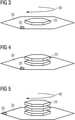
Fig. 1 und 2 auf das erste Grünteil gedruckt wird, schematisch in einer perspektivischen Darstellung, - Fig. 5
- einen weiteren Schritt des erfindungsgemäßen Verfahrens, bei welchem ein weiteres Grünteil nach den Verfahrensschritten gemäß
Fig. 1 und 2 auf die vorhandenen Grünteile gedruckt wird, schematisch in einer perspektivischen Darstellung, - Fig. 6
- einen weiteren Schritt des erfindungsgemäßen Verfahrens, bei welchem die in den Verfahrensschritten gemäß der
Figuren 1 bis 5 gedruckten Grünteile gemeinsam gesintert werden, sowie - Fig. 7
- einen letzten Schritt des erfindungsgemäßen Verfahrens, bei welchem der bei den Verfahrensschritten gem.
Figuren 1 bis 6 gefertigte Magnetblechstapel in eine elektrische Maschine einer erfindungsgemäßen Anlage eingebaut wird.
- 1
- a first step of the method according to the invention for manufacturing an electrical machine, in which a first green part of a magnetic sheet is printed, schematically in a perspective view,
- 2
- a second step of the method according to the invention, in which a suspension with ceramic particles is sprayed onto the first green part, schematically in a perspective view,
- 3
- a configuration of the first green part according to the method steps according to
Figures 1 and 2 schematically in a perspective representation, - 4
- a further step of the method according to the invention, in which a further green part according to the method steps
Figures 1 and 2 is printed on the first green part, schematically in a perspective view, - figure 5
- a further step of the method according to the invention, in which a further green part according to the method steps
Figures 1 and 2 is printed on the existing green parts, schematically in a perspective view, - 6
- a further step of the method according to the invention, in which the in the process steps according to
Figures 1 to 5 printed green parts are sintered together, as well as - 7
- a last step of the method according to the invention, in which the in the method steps acc.
Figures 1 to 6 manufactured stack of magnets is installed in an electrical machine of a system according to the invention.
Das in den
Die Magnetbleche werden bei dem erfindungsgemäßen Verfahren in einem Siebdruckverfahren mittels Schablonendrucks gedruckt. Dazu wird bei dem erfindungsgemäßen Verfahren zunächst eine Druckpaste 10 von Metallpulvern, im dargestellten Ausführungsbeispiel von Reineisenpulvern, hergestellt. Mittels der Druckpaste 10 wird ein erster Grünkörper 20 auf ein Substrat 30 gedruckt.In the method according to the invention, the magnetic sheets are printed in a screen printing process by means of stencil printing. For this purpose, in the method according to the invention, a
Der Grünkörper 20 soll nach einem nachfolgend näher erläuterten Sinterschritt ein Magnetblech bilden und weist die Gestalt einer dünnen Schicht auf dem Substrat 30 auf, sodass der Grünkörper 20 eine untere Flachseite aufweist, mit welchem er an dem Substrat 30 anliegt und eine von der unteren Flachseite abgewandte und zu dieser sich parallel erstreckende obere Flachseite aufweist.After a sintering step explained in more detail below, the
Zum Druck des Grünkörpers 20 wird ein Drucksieb (nicht explizit in der Zeichnung dargestellt) mit einer Schablone (nicht explizit in der Zeichnung dargestellt) herangezogen, um die Form des Grünkörpers 20 in flächigen Richtungen des Substrats 30 festzulegen. Eine Düse 40 druckt die Druckpaste 10 durch das Sieb auf das Substrat 30. Das Substrat 30 trägt eine Orientierungsmarkierung 50, mittels welcher die Orientierung des Substrats 30 und folglich auch des ersten Grünkörpers 20 leicht erkennbar sind. Erster Grünkörper 20 und Substrat 30 weisen im dargestellten Ausführungsbeispiel eine 6-fache Drehsymmetrie auf. In weiteren nicht eigens dargestellten Ausführungsbeispielen kann eine abweichende Drehsymmetrie, etwa eine 50-fache Drehsymmetrie oder eine sonstige Drehsymmetrie, vorliegen.A printing screen (not shown explicitly in the drawing) with a template (not shown explicitly in the drawing) is used to print the
Nachdem der erste Grünkörper 20 gedruckt ist, kann der erste Grünkörper 20 optional teilweise oder vollständig getrocknet werden.After the first
Nachfolgend wird mittels einer Düse 60 auf die obere Flachseite des ersten Grünkörpers 20 als Trennschicht eine Suspension 70 aufgesprüht, welche eine flüchtige Trägerflüssigkeit und in der Trägerflüssigkeit gehaltene Keramikpartikel 80 beinhaltet.Subsequently, a
Die Keramikpartikel 80 der Suspension 70 weisen im dargestellten Ausführungsbeispiel eine sphärische Gestalt und einen mittleren Partikeldurchmesser von weniger als 5 Mikrometern auf und sind mit Aluminiumoxid, d.h. mit Al2O3, gebildet. Alternativ oder zusätzlich können die Keramikpartikel in weiteren Ausführungsbeispielen auch Partikel aus Magnesiumoxid und/oder Yttriumoxid und/oder Aluminiumnitrid und/oder Bornitrid sein. Alternativ oder zusätzlich können die Keramikpartikel YAG- und/oder Glimmerpartikeln umfassen.In the exemplary embodiment shown, the
Die Größenverteilung der Keramikpartikel ist im dargestellten Ausführungsbeispiel eine bimodale Größenverteilung, d.h. es sind kleinere Keramikpartikel 80 in Sinne einer Feinfraktion der Keramikpartikel vorhanden, welche als Sinterinhibitoren zwischen Grünkörpern 20 fungieren und es sind gröbere Keramikpartikel 80 vorhanden, welche als Abstandshalter zwischen Grünkörper 20 fungieren können und eine elektrische Isolierung zwischen aus den Grünkörpern 20 gefertigten Magnetblechen ermöglichen.In the illustrated embodiment, the size distribution of the ceramic particles is a bimodal size distribution, i.e. there are smaller
In weiteren, nicht eigens dargestellten Ausführungsbeispielen können die Keramikpartikel eine whisker- oder plättchenförmige Gestalt aufweisen. Anstelle einer Suspension mit den Keramikpartikeln kann in weiteren, nicht eigens gezeigten Ausführungsbeispielen auch eine Grünfolie mit Keramikpartikeln auf den Grünkörper 20 aufgetragen werden.In further exemplary embodiments that are not specifically illustrated, the ceramic particles can have a whisker-like or platelet-like shape. Instead of a suspension with the ceramic particles, a green film with ceramic particles can also be applied to the
Die Keramikpartikel 80 bilden eine Trennschicht von weniger als 10 Mikrometern Dicke aus, welche mehr als 75 Prozent der Flachseiten des Grünteils 20 bedeckt.The
Im dargestellten Ausführungsbeispiel wurden die Keramikpartikel 80 mittels der Suspension 70 aufgetragen, welche zunächst getrocknet wird, sodass die Trägerflüssigkeit der Suspension 70 verfliegen kann.In the exemplary embodiment shown, the
Anschließend wird wie in
Nach der Drehung 90 um 60 Grad wird auf die mit Keramikpartikeln 80 gebildeten Trennschicht ein weiterer Grünkörper 20 wie in
Nachfolgend wird wie anhand von
Auf diese Weise wird weiter verfahren, bis eine vorgegebene Anzahl von Grünkörpern 20 aufeinander abgeschieden worden ist. Wie zuvor beschrieben wird die Anordnung von bereits gedruckten Grünkörpern 20 um einem Winkel von 60° gedreht, bevor ein neuer Grünkörper 20 gedruckt wird. Nach dem letzten Druck eines Grünkörpers 20 wird auf eine weitere Aufbringung einer Trennschicht mit Keramikpartikeln 80 verzichtet.The process continues in this way until a predetermined number of
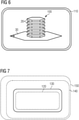
Auf diese Weise bilden die aufeinander gedruckten und jeweils durch Trennschichten mit Keramikpartikeln 80 voneinander getrennten Grünkörper 20 einen Stapel 100 von Grünkörpern 20. Der derart gebildete Stapel 100 von Grünkörpern 20 wird nun gemeinsam als Stapel 100 entbindert und in einem Sinterofen 110 gesintert. Auf diese Weise werden die Grünkörper 20 zu einem Stapel 100 von Magnetblechen gesintert.In this way, the
Optional können in einem weiteren Schritt die Keramikpartikel 80 zwischen den Magnetblechen entfernt werden.Optionally, the
Optional kann der Stapel 100 in Harz getaucht werden, sodass in dem Stapel 100 von Magnetblechen die einzelnen Magnetbleche zuverlässig voneinander elektrisch isoliert sind und der Stapel 100 mechanisch gefestigt wird.Optionally, the
Der Stapel 100 wird nun in an sich bekannter Weise mit einer Welle (nicht explizit gezeigt) versehen, sodass er einen Rotor 120 bildet. Der Rotor 120 wird in an sich bekannter Weise gemeinsam mit einem Stator 130 zu einer erfindungsgemäß gefertigten Maschine 140 verbaut, welche im gezeigten Ausführungsbeispiel ein erfindungsgemäß gefertigter Elektromotor ist. Alternativ oder zusätzlich kann die erfindungsgemäß gefertigte Maschine 140 einen elektrischen Generator bilden.The
Die in
Claims (11)
Priority Applications (3)
| Application Number | Priority Date | Filing Date | Title |
|---|---|---|---|
| EP20193708.3A EP3960334A1 (en) | 2020-08-31 | 2020-08-31 | Method for manufacturing an electric machine and installation and vehicle |
| US17/460,486 US11888362B2 (en) | 2020-08-31 | 2021-08-30 | Method to manufacture an electric machine, installation, vehicle |
| CN202111013726.5A CN114123675A (en) | 2020-08-31 | 2021-08-31 | Method and device for producing an electric machine and vehicle |
Applications Claiming Priority (1)
| Application Number | Priority Date | Filing Date | Title |
|---|---|---|---|
| EP20193708.3A EP3960334A1 (en) | 2020-08-31 | 2020-08-31 | Method for manufacturing an electric machine and installation and vehicle |
Publications (1)
| Publication Number | Publication Date |
|---|---|
| EP3960334A1 true EP3960334A1 (en) | 2022-03-02 |
Family
ID=72292434
Family Applications (1)
| Application Number | Title | Priority Date | Filing Date |
|---|---|---|---|
| EP20193708.3A Pending EP3960334A1 (en) | 2020-08-31 | 2020-08-31 | Method for manufacturing an electric machine and installation and vehicle |
Country Status (3)
| Country | Link |
|---|---|
| US (1) | US11888362B2 (en) |
| EP (1) | EP3960334A1 (en) |
| CN (1) | CN114123675A (en) |
Families Citing this family (1)
| Publication number | Priority date | Publication date | Assignee | Title |
|---|---|---|---|---|
| EP3960334A1 (en) * | 2020-08-31 | 2022-03-02 | Siemens Aktiengesellschaft | Method for manufacturing an electric machine and installation and vehicle |
Citations (5)
| Publication number | Priority date | Publication date | Assignee | Title |
|---|---|---|---|---|
| DE102012015127A1 (en) * | 2012-07-27 | 2014-02-13 | Fraunhofer-Gesellschaft zur Förderung der angewandten Forschung e.V. | Sintering substrate arranged between green solid molded body to be sintered and base body, comprises green solid film disposed on metallic or ceramic carrier and separating layer made of material disposed between green solid molded body |
| DE102014104596A1 (en) * | 2014-04-01 | 2015-10-01 | Bundesrepublik Deutschland, Vertreten Durch Den Bundesminister Für Wirtschaft Und Energie, Dieser Vertreten Durch Den Präsidenten Der Bundesanstalt Für Materialforschung Und -Prüfung (Bam) | Structure of a diffusion barrier in a slip-based additive manufacturing process for the production of a ceramic green body |
| WO2020043565A1 (en) * | 2018-08-31 | 2020-03-05 | Siemens Aktiengesellschaft | Method for producing sinter, sintering device, and method for producing an electrical machine |
| WO2020064299A1 (en) * | 2018-09-27 | 2020-04-02 | Siemens Aktiengesellschaft | Method for sintering a multicomponent object to be sintered, electric machine, and electric vehicle |
| EP3653320A1 (en) * | 2018-11-16 | 2020-05-20 | Siemens Aktiengesellschaft | Method for sintering sintering material |
Family Cites Families (9)
| Publication number | Priority date | Publication date | Assignee | Title |
|---|---|---|---|---|
| DE2145553C3 (en) * | 1971-09-11 | 1979-07-19 | Loi Industrieofenanlagen Gmbh, 4300 Essen | Process for the production of laminated cores for the field-leading parts of electrical machines and devices |
| US6121709A (en) * | 1997-10-16 | 2000-09-19 | Alliedsignal Inc. | Rotor assembly having bonded lamination stack |
| US7224096B2 (en) * | 1997-10-16 | 2007-05-29 | Honeywell International Inc. | Rotatable assemblies having chemically bonded lamination stacks |
| GB0616116D0 (en) * | 2006-08-12 | 2006-09-20 | Rolls Royce Plc | A method of forming a component on a substrate |
| CN201478887U (en) * | 2009-08-31 | 2010-05-19 | 吕元之 | Soft magnetic composite material motor core |
| DE102015216969A1 (en) * | 2015-09-04 | 2017-03-09 | Robert Bosch Gmbh | Coated sintered material, process for its production and uses of the coated sintered material |
| DE102016203739A1 (en) * | 2016-03-08 | 2017-09-14 | Brose Fahrzeugteile GmbH & Co. Kommanditgesellschaft, Würzburg | Package system of an electric machine, electric machine and method of manufacturing the package system |
| CN109961915A (en) * | 2019-03-05 | 2019-07-02 | 宁波金科磁业有限公司 | A kind of magnetic sheet forming method |
| EP3960334A1 (en) * | 2020-08-31 | 2022-03-02 | Siemens Aktiengesellschaft | Method for manufacturing an electric machine and installation and vehicle |
-
2020
- 2020-08-31 EP EP20193708.3A patent/EP3960334A1/en active Pending
-
2021
- 2021-08-30 US US17/460,486 patent/US11888362B2/en active Active
- 2021-08-31 CN CN202111013726.5A patent/CN114123675A/en active Pending
Patent Citations (5)
| Publication number | Priority date | Publication date | Assignee | Title |
|---|---|---|---|---|
| DE102012015127A1 (en) * | 2012-07-27 | 2014-02-13 | Fraunhofer-Gesellschaft zur Förderung der angewandten Forschung e.V. | Sintering substrate arranged between green solid molded body to be sintered and base body, comprises green solid film disposed on metallic or ceramic carrier and separating layer made of material disposed between green solid molded body |
| DE102014104596A1 (en) * | 2014-04-01 | 2015-10-01 | Bundesrepublik Deutschland, Vertreten Durch Den Bundesminister Für Wirtschaft Und Energie, Dieser Vertreten Durch Den Präsidenten Der Bundesanstalt Für Materialforschung Und -Prüfung (Bam) | Structure of a diffusion barrier in a slip-based additive manufacturing process for the production of a ceramic green body |
| WO2020043565A1 (en) * | 2018-08-31 | 2020-03-05 | Siemens Aktiengesellschaft | Method for producing sinter, sintering device, and method for producing an electrical machine |
| WO2020064299A1 (en) * | 2018-09-27 | 2020-04-02 | Siemens Aktiengesellschaft | Method for sintering a multicomponent object to be sintered, electric machine, and electric vehicle |
| EP3653320A1 (en) * | 2018-11-16 | 2020-05-20 | Siemens Aktiengesellschaft | Method for sintering sintering material |
Also Published As
| Publication number | Publication date |
|---|---|
| CN114123675A (en) | 2022-03-01 |
| US20220069680A1 (en) | 2022-03-03 |
| US11888362B2 (en) | 2024-01-30 |
Similar Documents
| Publication | Publication Date | Title |
|---|---|---|
| EP1597780B1 (en) | Electrical multilayered component and layer stack | |
| DE102016119650A1 (en) | Process for producing a soft magnetic core material | |
| WO2020207739A1 (en) | Method for manufacturing a magnetic sheet and a stack of magnetic sheets and electric machine and electric vehicle | |
| EP1430489A2 (en) | Electroceramic component comprising a plurality of contact surfaces | |
| EP3932591A1 (en) | Magnetic sheet, method for producing same, rotor and electrical machine | |
| DE102016119654A1 (en) | Process for producing a soft magnetic core material | |
| DE10060653A1 (en) | Electric double layer capacitor | |
| EP3960334A1 (en) | Method for manufacturing an electric machine and installation and vehicle | |
| WO2022117278A1 (en) | Material layer, material layer stack for an electric machine and method for producing a material layer | |
| WO2021185398A1 (en) | Method for producing a layer assembly from electrical sheet metal, accordingly produced layer assembly, rotor or stator and electric motor | |
| EP3859953A1 (en) | Laminated core for an electric rotating machine | |
| EP4222764B1 (en) | Method for producing a metallic layer with at least one recess | |
| DE102022119376A1 (en) | Electrical sheet for an electrical machine and method for producing an electrical sheet | |
| DE10039649B4 (en) | Method for producing a ceramic multilayer component and corresponding multilayer component | |
| EP3975383A1 (en) | Electric machine, method and system | |
| WO2020224927A1 (en) | Magnetic sheet stack, method for manufacturing a magnetic sheet stack and electric machine | |
| WO2022069291A1 (en) | Electric machine and installation | |
| WO2019029920A1 (en) | Method for through-plating a printed circuit board and such a printed circuit board | |
| EP3979465A1 (en) | Electrical machine and system | |
| WO2023104434A1 (en) | Method for producing a laminated core of an electric machine | |
| WO2023104431A1 (en) | Method for producing a laminated core of an electric machine | |
| EP3731372A1 (en) | Magnetic sheet stack and method for producing same | |
| DE102022129023A1 (en) | Method for applying a metallic layer to a surface of a ceramic body | |
| WO2024046645A1 (en) | Additively manufactured magnetic lamination, laminated core and method for manufacturing a magnetic lamination | |
| WO2020099037A1 (en) | Electrical steel sheet having a structured surface for domain refining |
Legal Events
| Date | Code | Title | Description |
|---|---|---|---|
| PUAI | Public reference made under article 153(3) epc to a published international application that has entered the european phase |
Free format text: ORIGINAL CODE: 0009012 |
|
| STAA | Information on the status of an ep patent application or granted ep patent |
Free format text: STATUS: THE APPLICATION HAS BEEN PUBLISHED |
|
| AK | Designated contracting states |
Kind code of ref document: A1 Designated state(s): AL AT BE BG CH CY CZ DE DK EE ES FI FR GB GR HR HU IE IS IT LI LT LU LV MC MK MT NL NO PL PT RO RS SE SI SK SM TR |
|
| STAA | Information on the status of an ep patent application or granted ep patent |
Free format text: STATUS: REQUEST FOR EXAMINATION WAS MADE |
|
| 17P | Request for examination filed |
Effective date: 20220831 |
|
| RBV | Designated contracting states (corrected) |
Designated state(s): AL AT BE BG CH CY CZ DE DK EE ES FI FR GB GR HR HU IE IS IT LI LT LU LV MC MK MT NL NO PL PT RO RS SE SI SK SM TR |