EP3960305A1 - Liquid detection device and liquid detection method - Google Patents
Liquid detection device and liquid detection method Download PDFInfo
- Publication number
- EP3960305A1 EP3960305A1 EP19926268.4A EP19926268A EP3960305A1 EP 3960305 A1 EP3960305 A1 EP 3960305A1 EP 19926268 A EP19926268 A EP 19926268A EP 3960305 A1 EP3960305 A1 EP 3960305A1
- Authority
- EP
- European Patent Office
- Prior art keywords
- liquid object
- dispensing
- container
- liquid
- dispenser
- Prior art date
- Legal status (The legal status is an assumption and is not a legal conclusion. Google has not performed a legal analysis and makes no representation as to the accuracy of the status listed.)
- Granted
Links
Images



Classifications
-
- A—HUMAN NECESSITIES
- A45—HAND OR TRAVELLING ARTICLES
- A45D—HAIRDRESSING OR SHAVING EQUIPMENT; EQUIPMENT FOR COSMETICS OR COSMETIC TREATMENTS, e.g. FOR MANICURING OR PEDICURING
- A45D34/00—Containers or accessories specially adapted for handling liquid toiletry or cosmetic substances, e.g. perfumes
-
- G—PHYSICS
- G01—MEASURING; TESTING
- G01V—GEOPHYSICS; GRAVITATIONAL MEASUREMENTS; DETECTING MASSES OR OBJECTS; TAGS
- G01V8/00—Prospecting or detecting by optical means
- G01V8/10—Detecting, e.g. by using light barriers
-
- B—PERFORMING OPERATIONS; TRANSPORTING
- B05—SPRAYING OR ATOMISING IN GENERAL; APPLYING FLUENT MATERIALS TO SURFACES, IN GENERAL
- B05B—SPRAYING APPARATUS; ATOMISING APPARATUS; NOZZLES
- B05B11/00—Single-unit hand-held apparatus in which flow of contents is produced by the muscular force of the operator at the moment of use
- B05B11/0005—Components or details
- B05B11/0037—Containers
- B05B11/0054—Cartridges, i.e. containers specially designed for easy attachment to or easy removal from the rest of the sprayer
-
- B—PERFORMING OPERATIONS; TRANSPORTING
- B05—SPRAYING OR ATOMISING IN GENERAL; APPLYING FLUENT MATERIALS TO SURFACES, IN GENERAL
- B05B—SPRAYING APPARATUS; ATOMISING APPARATUS; NOZZLES
- B05B11/00—Single-unit hand-held apparatus in which flow of contents is produced by the muscular force of the operator at the moment of use
- B05B11/01—Single-unit hand-held apparatus in which flow of contents is produced by the muscular force of the operator at the moment of use characterised by the means producing the flow
- B05B11/10—Pump arrangements for transferring the contents from the container to a pump chamber by a sucking effect and forcing the contents out through the dispensing nozzle
-
- B—PERFORMING OPERATIONS; TRANSPORTING
- B05—SPRAYING OR ATOMISING IN GENERAL; APPLYING FLUENT MATERIALS TO SURFACES, IN GENERAL
- B05B—SPRAYING APPARATUS; ATOMISING APPARATUS; NOZZLES
- B05B11/00—Single-unit hand-held apparatus in which flow of contents is produced by the muscular force of the operator at the moment of use
- B05B11/01—Single-unit hand-held apparatus in which flow of contents is produced by the muscular force of the operator at the moment of use characterised by the means producing the flow
- B05B11/10—Pump arrangements for transferring the contents from the container to a pump chamber by a sucking effect and forcing the contents out through the dispensing nozzle
- B05B11/1042—Components or details
- B05B11/1052—Actuation means
-
- B—PERFORMING OPERATIONS; TRANSPORTING
- B05—SPRAYING OR ATOMISING IN GENERAL; APPLYING FLUENT MATERIALS TO SURFACES, IN GENERAL
- B05B—SPRAYING APPARATUS; ATOMISING APPARATUS; NOZZLES
- B05B11/00—Single-unit hand-held apparatus in which flow of contents is produced by the muscular force of the operator at the moment of use
- B05B11/01—Single-unit hand-held apparatus in which flow of contents is produced by the muscular force of the operator at the moment of use characterised by the means producing the flow
- B05B11/10—Pump arrangements for transferring the contents from the container to a pump chamber by a sucking effect and forcing the contents out through the dispensing nozzle
- B05B11/1081—Arrangements for pumping several liquids or other fluent materials from several containers, e.g. for mixing them at the moment of pumping
- B05B11/1084—Arrangements for pumping several liquids or other fluent materials from several containers, e.g. for mixing them at the moment of pumping each liquid or other fluent material being pumped by a separate pump
-
- B—PERFORMING OPERATIONS; TRANSPORTING
- B05—SPRAYING OR ATOMISING IN GENERAL; APPLYING FLUENT MATERIALS TO SURFACES, IN GENERAL
- B05B—SPRAYING APPARATUS; ATOMISING APPARATUS; NOZZLES
- B05B12/00—Arrangements for controlling delivery; Arrangements for controlling the spray area
- B05B12/08—Arrangements for controlling delivery; Arrangements for controlling the spray area responsive to condition of liquid or other fluent material to be discharged, of ambient medium or of target ; responsive to condition of spray devices or of supply means, e.g. pipes, pumps or their drive means
- B05B12/082—Arrangements for controlling delivery; Arrangements for controlling the spray area responsive to condition of liquid or other fluent material to be discharged, of ambient medium or of target ; responsive to condition of spray devices or of supply means, e.g. pipes, pumps or their drive means responsive to a condition of the discharged jet or spray, e.g. to jet shape, spray pattern or droplet size
-
- B—PERFORMING OPERATIONS; TRANSPORTING
- B05—SPRAYING OR ATOMISING IN GENERAL; APPLYING FLUENT MATERIALS TO SURFACES, IN GENERAL
- B05B—SPRAYING APPARATUS; ATOMISING APPARATUS; NOZZLES
- B05B12/00—Arrangements for controlling delivery; Arrangements for controlling the spray area
- B05B12/08—Arrangements for controlling delivery; Arrangements for controlling the spray area responsive to condition of liquid or other fluent material to be discharged, of ambient medium or of target ; responsive to condition of spray devices or of supply means, e.g. pipes, pumps or their drive means
- B05B12/12—Arrangements for controlling delivery; Arrangements for controlling the spray area responsive to condition of liquid or other fluent material to be discharged, of ambient medium or of target ; responsive to condition of spray devices or of supply means, e.g. pipes, pumps or their drive means responsive to conditions of ambient medium or target, e.g. humidity, temperature position or movement of the target relative to the spray apparatus
- B05B12/122—Arrangements for controlling delivery; Arrangements for controlling the spray area responsive to condition of liquid or other fluent material to be discharged, of ambient medium or of target ; responsive to condition of spray devices or of supply means, e.g. pipes, pumps or their drive means responsive to conditions of ambient medium or target, e.g. humidity, temperature position or movement of the target relative to the spray apparatus responsive to presence or shape of target
-
- B—PERFORMING OPERATIONS; TRANSPORTING
- B05—SPRAYING OR ATOMISING IN GENERAL; APPLYING FLUENT MATERIALS TO SURFACES, IN GENERAL
- B05B—SPRAYING APPARATUS; ATOMISING APPARATUS; NOZZLES
- B05B12/00—Arrangements for controlling delivery; Arrangements for controlling the spray area
- B05B12/14—Arrangements for controlling delivery; Arrangements for controlling the spray area for supplying a selected one of a plurality of liquids or other fluent materials or several in selected proportions to a spray apparatus, e.g. to a single spray outlet
- B05B12/1409—Arrangements for controlling delivery; Arrangements for controlling the spray area for supplying a selected one of a plurality of liquids or other fluent materials or several in selected proportions to a spray apparatus, e.g. to a single spray outlet the selection means being part of the discharge apparatus, e.g. part of the spray gun
-
- A—HUMAN NECESSITIES
- A45—HAND OR TRAVELLING ARTICLES
- A45D—HAIRDRESSING OR SHAVING EQUIPMENT; EQUIPMENT FOR COSMETICS OR COSMETIC TREATMENTS, e.g. FOR MANICURING OR PEDICURING
- A45D34/00—Containers or accessories specially adapted for handling liquid toiletry or cosmetic substances, e.g. perfumes
- A45D2034/005—Containers or accessories specially adapted for handling liquid toiletry or cosmetic substances, e.g. perfumes with a cartridge
-
- A—HUMAN NECESSITIES
- A45—HAND OR TRAVELLING ARTICLES
- A45D—HAIRDRESSING OR SHAVING EQUIPMENT; EQUIPMENT FOR COSMETICS OR COSMETIC TREATMENTS, e.g. FOR MANICURING OR PEDICURING
- A45D2200/00—Details not otherwise provided for in A45D
- A45D2200/05—Details of containers
- A45D2200/054—Means for supplying liquid to the outlet of the container
-
- B—PERFORMING OPERATIONS; TRANSPORTING
- B05—SPRAYING OR ATOMISING IN GENERAL; APPLYING FLUENT MATERIALS TO SURFACES, IN GENERAL
- B05B—SPRAYING APPARATUS; ATOMISING APPARATUS; NOZZLES
- B05B11/00—Single-unit hand-held apparatus in which flow of contents is produced by the muscular force of the operator at the moment of use
- B05B11/01—Single-unit hand-held apparatus in which flow of contents is produced by the muscular force of the operator at the moment of use characterised by the means producing the flow
- B05B11/10—Pump arrangements for transferring the contents from the container to a pump chamber by a sucking effect and forcing the contents out through the dispensing nozzle
- B05B11/1042—Components or details
- B05B11/108—Means for counting the number of dispensing strokes
Definitions
- the container 500 includes an RFID tag 550 at the bottom surface part of the body 510.
- the RFID tag 550 stores a unique identifier attached to each container 500, information on the product type of the liquid object (stored liquid) stored in the container 500, and the expiration date, the remaining amount, etc., of the liquid object. Because the container 500 includes the RFID tag 550, it is possible to manage the use-by date and the amount of use of the liquid object (stored liquid) stored in the container 500, prevent wrong insertion of the container 500, prevent distribution of counterfeit products, and ensure the traceability of the container 500 and the liquid object (stored liquid) stored in the container 500.
- FIG. 6(B) depicts a state where the turntable 110 has rotated 36 degrees in the direction of arrow A from the state illustrated in FIG. 6(A).
- FIG. 6(B) depicts a state where the middle part between the container 501 and the container 502 is positioned over the extraction opening 106.
- the position opposite to the dispensing position PosA relative to the rotary shaft 112 (the position of the container 504 in FIG. 6(B) ) is referred to as replacement position PosB.
- the container 504 (500) also rotates 36° to be positioned at PosB.
- the container 500 at the replacement position PosB is exposed to the outside. The user can replace the container 500 at the replacement position PosB with another container 500.
- the container 500 is an example of a liquid object dispensing part. Furthermore, the dispensing mechanism 130 is an example of a pressing part.
- the device control part 141 controls the entire device.
- the communication control part 142 controls communications between the liquid object dispenser 100 and the information processing terminal 200 and the server apparatus 300.
- the communication control part 142 controls a communication part 180 provided in the liquid object dispenser 100.
- the communication part 180 performs communications with the information processing terminal 200 and the server apparatus 300 via the network 400 based on the control of the communication control part 142.
- the communication part 180 performs communications through, for example, short-range communications based on Bluetooth (registered trademark) or the like, wireless LAN (Local Area Network) communications, mobile communications based on LTE (Long Term Evolution) or the like, etc.
- the rotation control part 143 controls the rotation of the turntable 110.
- the turntable 110 is connected to a rotation motor 113.
- the rotation control part 143 controls the rotation of the turntable 110 by controlling the rotation of the rotation motor 113.
- the RFID control part 148 controls the input and output of information recorded in the RFID tag 550 of the container 500.
- the RFID control part 148 controls an RFID reader writer 190 provided in the liquid object dispenser 100 to read information from and write information to the RFID tag 550 of the container 500.
- the server apparatus 300 determines the type and amount of a liquid object dispensed from the liquid object dispenser 100 used by a user from personal information such as the age, skin characteristics, skin condition, etc., of the user, the environmental information such as temperature, humidity, and weather of the day of use, time information, etc.
- personal information such as the age, skin characteristics, skin condition, etc.
- the environmental information such as temperature, humidity, and weather of the day of use, time information, etc.
- the liquid object dispenser 100 dispenses one or more types of liquid objects corresponding to the containers 500 housed in the liquid object dispenser 100.
- the liquid object dispenser 100 dispenses each liquid object based on the amount in the dispensing liquid information.
- the device control part 141 of the liquid object dispenser 100 identifies the container 500 from which to dispense a liquid object among the containers 500 (501, 502, 503, 504, 505) accommodated in the liquid object dispenser 100, from the dispensing liquid information received from the server apparatus 300.
- the device control part 141 calculates the amount of the liquid object to dispense, namely, the number of times the push button 522 is pressed, with respect to the identified dispensing container 500.
- the device control part 141 rotationally transfers the container accommodating part 120 of the container 500 from which to dispense the liquid object to the dispensing position PosA by controlling the rotation control part 143.
- the device control part 141 controls the dispensing control part 144 to press the push button 522 of the container 500 the calculated number of times to dispense the liquid object.
- FIG. 9 is an enlarged view of the part of the dispensing detector 160 of the liquid object dispenser 100. Furthermore, FIG. 10 is a functional block diagram of the dispensing detector of an example of the liquid object dispenser according to this embodiment.
- the light that the light emitter part 1611 outputs is light of a wavelength absorbed by or reflected from the liquid object. Accordingly, when there is the liquid object in the sensor sensing range between the light emitter part 1611 and the light receiver part 1612, the output light of the light emitter part 1611 is blocked by the liquid object, so that the amount of light received at the light receiver part 1612 is reduced. Thus, it is possible to detect whether the liquid object is dispensed in the sensor sensing range by the presence or absence of reduction in light.
- the sensors 162 and 163 are sensors equal to the sensor 161. That is, the sensors 162 and 163 include respective light emitter parts 1621 and 1631 and respective light receiver parts 1622 and 1632. The sensors 162 and 163 operate the same as the sensor 161.
- the plate 164 on which the sensors 161, 162 and 163 are placed is described.
- the plate 164 includes a light emitter part placement part 1641, a light receiver part placement part 1642, and an opening 1643.
- the light emitter parts 1611, 1621 and 1631 of the sensors 161, 162 and 163 are placed on the light emitter part placement part 1641.
- the light receiver parts 1612, 1622 and 1632 of the sensors 161, 162 and 163 are placed on the light receiver part placement part 1642.
- the light emitter part placement part 1641 and the light receiver part placement part 1642 are placed across the opening 1643 from each other.
- a space above the opening 1643 of the plate 164 serves as the respective sensor sensing ranges of the sensors 161, 162 and 163.
- the liquid object dispensed from the dispensing opening 526 of the container 500 is dispensed from the extraction opening 106 through the opening 1643.
- the light emitter parts and the light receiver parts of sensors are placed at different locations on the plate 164, as on the light emitter part placement part 1641 and the light receiver part placement part 1642.
- the arrangement of light emitter parts and light receiver parts may be changed to the extent that the sensors are so placed as to have their sensor sensing ranges above the opening 1643.
- the respective light emitter part, light receiver part, and light emitter part of sensors may be placed in order on one side and the corresponding light receiver part, light emitter part, and light receiver part of the sensors may be placed in order on the other side of the opening 1643.
- the cam plate 165 includes a diagonally formed inclined groove 1651 and a laterally formed lateral groove 1652.
- a protrusion 1342 protruding from the slide member 134 of the dispensing mechanism 130 is fit into the inclined groove 1651.
- a protrusion 1351 protruding from the fixing member 135 of the dispensing mechanism 130 is fit into the lateral groove 1652.
- the top of the cam plate 165 is so held by a holding member 1352 protruding from the fixing member 135 of the dispensing mechanism 130 as not to move upward.
- the slide member 134 of the dispensing mechanism 130 slides upward.
- the upward slide of the slide member 134 moves the protrusion 1342 of the slide member 134 upward.
- the protrusion 1342 is fit into the inclined groove 1651 of the cam plate 165. Therefore, the protrusion 1342 moves upward to move along the inclined groove 1651 of the cam plate 165.
- the upward and downward movements of the cam plate 165 are restricted by the protrusion 1351 of the fixing member 135 fit into the lateral groove 1652 and the holding member 1352.
- the protrusion 1342 moves upward, the protrusion 1342 moves along the inclined groove 1651 of the cam plate 165 to move the cam plate 165 in a lateral direction, namely, a direction that crosses the dispensing direction of the liquid object, so that the plate 164 moves in the lateral direction, namely, a direction that crosses the dispensing direction of the liquid object.
- the sensors 161, 162 and 163 provided on the plate 164 move in the lateral direction, namely, a direction that crosses the direction in which the liquid object is dispensed from the dispensing opening 526 of the container 500 (the dispensing direction), which is the same direction as a direction in which the sensors 161, 162 and 163 are arranged.
- the plate 164 is an example of a retaining member that retains sensors.
- the cam plate 165 and the dispensing mechanism 130 is an example of a sensor moving part.
- the dispensing detector 160 is an example of a liquid object detector.
- the plate 164 is interlocked with the dispensing mechanism 130 that dispenses a liquid object from the container 500, specifically, the slide member 134 that presses the push button 522 of the container 500 to cause a liquid object to be dispensed.
- the dispensing detector 160 has the sensors 161, 162 and 163 that detect whether a liquid object has been dispensed arranged in a direction that crosses a direction in which the liquid object is dispensed from the dispensing opening 526 of the container 500 (dispensing direction). Because of this, for example, in the case where the sensor 162 is supposed to detect a liquid object, even when, for example, the dispensing direction shifts because of adhesion of the liquid object to the dispensing opening 526 to be off the sensor sensing range of the sensor 162, it is possible to detect the liquid object with the sensor 161 or 163. Accordingly, by having multiple sensors provided in a direction that crosses the dispensing direction of a liquid object as the sensors 161, 162 and 163, it is possible to stably detect the liquid object.
- the plate 164 of the dispensing detector 160 of this embodiment moves in directions that cross a direction in which the liquid object is dispensed from the dispensing opening 526 of the container 500 (dispensing direction) and are the same as directions in which the sensors 161, 162 and 163 are arranged (the directions of arrow M in FIG. 9 ).
- the dispensing mechanism 130 that presses the container 500 that constitutes a push pump and the cam plate 165 that moves the plate 164 are interlocked, thereby making it possible to move the sensors to the dispensing of a liquid object. This makes it possible to stably detect the liquid object.
- the server apparatus 300 manages the state of the liquid object dispenser 100. For example, the server apparatus 300 manages the remaining amount of a liquid object stored in the container 500 of the liquid object dispenser 100.
- Use of the dispensing detector 160 of this embodiment makes it possible to accurately manage the remaining amount by detecting the dispensing of the liquid object.
- the number of sensors of the dispensing detector 160 is not limited to three.
- the number of sensors of the dispensing detector 160 may be two or four or more.
Landscapes
- Physics & Mathematics (AREA)
- Life Sciences & Earth Sciences (AREA)
- General Life Sciences & Earth Sciences (AREA)
- General Physics & Mathematics (AREA)
- Geophysics (AREA)
- Coating Apparatus (AREA)
- Containers And Packaging Bodies Having A Special Means To Remove Contents (AREA)
- Automatic Analysis And Handling Materials Therefor (AREA)
- Devices For Dispensing Beverages (AREA)
Abstract
Description
- The present invention relates to liquid object detectors and liquid object detecting methods.
- A dispenser that automatically dispenses and supplies a cosmetic or the like stored in a storage tank has been known (Patent Document 1).
- Patent Document 1:
International Publication No. 2016/029104 - According to the conventional art, however, whether a liquid object has actually been dispensed from the storage tank in which the liquid object is stored is not detected and is unclear when the liquid object is dispensed from the dispenser.
- An embodiment of the present invention has an object of providing a device and a method that can stably detect the dispensing of a liquid object in a liquid object dispenser.
- A liquid object detector according to the disclosure includes a liquid object dispensing part, a sensor configured to detect a liquid object dispensed by the liquid object dispensing part, and a sensor moving part configured to move the sensor in a direction crossing a dispensing direction of the liquid obj ect.
- It is possible to stably detect the dispensing of a liquid object in a liquid object dispenser.
-
-
FIG. 1 is an overall configuration diagram of an example of a liquid object dispensing system according to this embodiment. -
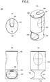
FIG. 2 is an overall view of an example of a liquid object dispenser according to this embodiment. -
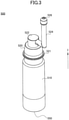
FIG. 3 is a perspective view of a container of an example of the liquid object dispenser according to this embodiment. -
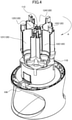
FIG. 4 is a perspective view of an example of the liquid object dispenser according to this embodiment, illustrating its internal structure. -
FIG. 5 is a perspective view of an example of the liquid object dispenser according to this embodiment, illustrating its internal structure. -
FIG. 6 illustrates top views of an example of the liquid object dispenser according to this embodiment, illustrating its internal structure. -
FIG. 7 is a perspective view of an example of the liquid object dispenser according to this embodiment, illustrating the details of a dispensing mechanism. -
FIG. 8 is a functional block diagram of an example of the liquid object dispenser according to this embodiment. -
FIG. 9 is an enlarged view of the part of a dispensing detector of an example of the liquid object dispenser according to this embodiment. -
FIG. 10 is a functional block diagram of the dispensing detector of an example of the liquid object dispenser according to this embodiment. - An embodiment of the present invention is described in detail below using the accompanying drawings.
-
FIG. 1 is an overall configuration diagram of an example of a liquidobject dispensing system 1 according to this embodiment. - The liquid
object dispensing system 1 according to this embodiment includes aliquid object dispenser 100, aninformation processing terminal 200, and aserver apparatus 300. The liquid object dispenser 100, theinformation processing terminal 200, and theserver apparatus 300 are connected via anetwork 400. Theliquid object dispenser 100 will be described later. Theinformation processing terminal 200 is, for example, a portable terminal such as a smartphone or a tablet computer. Theinformation processing terminal 200 transmits user information, etc., to theserver apparatus 300. Theserver apparatus 300 is an information processor (computer) that executes processes as a server. Theserver apparatus 300 manages a user of theliquid object dispenser 100 and the state of theliquid object dispenser 100. Furthermore, theserver apparatus 300 determines the manner in which the liquid object dispenser 100 is caused to operate, based on user information, etc., transmitted from theinformation processing terminal 200 and weather information, etc., open to the public. - According to the liquid
object dispensing system 1 of this embodiment, theliquid object dispenser 100 receives information on the operation of the liquid object dispenser 100 (operation information) from theserver apparatus 300 via thenetwork 400. The liquid object dispenser 100 executes processes based on the received operation information. Furthermore, the liquid object dispenser 100 transmits the results of the processes executed based on the received operation information to theserver apparatus 300. Theserver apparatus 300 updates information on the state of theliquid object dispenser 100, etc. - According to
FIG. 1 , the liquid object dispenser 100, theinformation processing terminal 200, and theserver apparatus 300, one each, are connected to thenetwork 400, but their respective numbers are not limited to those ofFIG. 1 . For example, multiple liquid object dispensers 100 and multipleinformation processing terminals 200 may be connected to thesingle server apparatus 300. Furthermore, the processes of theserver apparatus 300 may be distributed between or among and executed bymultiple server apparatuses 300. Moreover, theliquid object dispenser 100 may be caused to operate independently without being connected to thenetwork 400. - Next, the
liquid object dispenser 100 is described. -
FIG. 2 is an overall view of an example of theliquid object dispenser 100 according to this embodiment.FIG. 2(A) is a top view (plan view) of theliquid object dispenser 100.FIG. 2(B) is a front view of theliquid object dispenser 100.FIG. 2(C) is a side view of theliquid object dispenser 100.FIG. 2(D) is a perspective view of theliquid object dispenser 100. - The
liquid object dispenser 100 includes anupper surface part 101, anupper housing 102, alower housing 103, and abottom surface part 104. Theliquid object dispenser 100 has a substantially cylindrical shape. Thelower housing 103 includes ahand insertion part 105. Furthermore, thelower housing 103 includes anextraction opening 106 and ahuman body sensor 107 above thehand insertion part 105. A user inserts a hand into thehand insertion part 105, and thehuman body sensor 107 detects the hand. In response to detection of the hand by thehuman body sensor 107, a stored liquid (liquid object) stored in a below-describedcontainer 500 is dispensed from theextraction opening 106. Theliquid object dispenser 100 includes acontainer lid 108. Thecontainer lid 108 is provided over theupper surface part 101 and theupper housing 102. The user opens thecontainer lid 108 to replace the below-describedcontainer 500 that is exposed through an opening exposed by the openedcontainer lid 108. Furthermore, theliquid object dispenser 100 includes a button (switch) 109 in theupper surface part 101. Once the user presses thebutton 109, the liquid object dispenser 100 starts to operate. - Next, the
container 500 is described. -
FIG. 3 is a perspective view of thecontainer 500 of an example of theliquid object dispenser 100 according to this embodiment. - The
container 500 is, for example, a container that stores a liquid object (stored liquid) such as a cosmetic such as an emulsion or a serum. With respect to emulsions, for example, multiple types of emulsions may be used for morning and for night. With respect to serums, for example, multiple types of serums for anti-oxidation, drying prevention, stress reduction, etc., may be used. - The
container 500 according to this embodiment includes abody 510 and alid 520. A stored liquid (liquid object) is stored in thebody 510. Thelid 520 is attached to thebody 510 by screwing or the like. Thelid 520 includes aflange 521, a push button (pressing member) 522, and apipe 524. A dispensingopening 526 from which the stored liquid (liquid object) is dispensed is provided at an end of thepipe 524 opposite to thepush button 522. The liquid object (stored liquid) in thecontainer 500 is dispensed in response to the pressing of thepush button 522. - The
body 510 of thecontainer 500 is an example of a storage part. Furthermore, thecontainer 500 operates as a push pump with thepush button 522 of thelid 520. - The
container 500 includes anRFID tag 550 at the bottom surface part of thebody 510. TheRFID tag 550 stores a unique identifier attached to eachcontainer 500, information on the product type of the liquid object (stored liquid) stored in thecontainer 500, and the expiration date, the remaining amount, etc., of the liquid object. Because thecontainer 500 includes theRFID tag 550, it is possible to manage the use-by date and the amount of use of the liquid object (stored liquid) stored in thecontainer 500, prevent wrong insertion of thecontainer 500, prevent distribution of counterfeit products, and ensure the traceability of thecontainer 500 and the liquid object (stored liquid) stored in thecontainer 500. - While the
container 500 of this embodiment uses theRFID tag 550, means for recording information on thecontainer 500 is not limited to RFID tags. For example, a barcode, etc., may also be used. - The
container 500 of this embodiment is accommodated in a below-described containeraccommodating part 120 of aturntable 110 of theliquid object dispenser 100 in such a manner that thepush button 522 faces downward. Specifically, thecontainer 500 is inserted into thecontainer accommodating part 120 in the direction of arrow I to be accommodated in thecontainer accommodating part 120. -
FIGS. 4 and5 are perspective views of an example of theliquid object dispenser 100 according to this embodiment, illustrating its internal structure.FIGS. 4 and5 are diagrams illustrating a state where theupper housing 102 and part of the inside of theupper housing 102 are removed to expose theturntable 110.FIG. 4 is a diagram illustrating a state where thecontainers 500 are not accommodated in thecontainer accommodating parts 120.FIG. 5 is a diagram illustrating a state where thecontainers 500 are accommodated in thecontainer accommodating parts 120. - The
liquid object dispenser 100 according to this embodiment includes theturntable 110 in theupper housing 102 and on top of thelower housing 103. Theturntable 110 rotates on arotary shaft 112 in the direction of arrow A or in a direction opposite to arrow A relative to theupper housing 102 and thelower housing 103. While theturntable 110 is used to rotationally transfer thecontainers 500 according to theliquid object dispenser 100 of this embodiment, the transfer method is not limited to rotation. For example, a transfer table that horizontally transfers thecontainer accommodating parts 120 on a straight line may also be used. Thus, theturntable 110 is movable relative to theupper housing 102 and thelower housing 103. Theturntable 110 is an example of a transfer table. - The
turntable 110 includes thecontainer accommodating parts 120 that accommodate thecontainers 500. The containeraccommodating parts 120 are disposed at regular intervals in the circumferential direction of a circle having a center at therotary shaft 112. Theturntable 110 of this embodiment includes thecontainer accommodating parts 120 at five places in total. The containeraccommodating parts 120 are designated ascontainer accommodating parts accommodating part 121 accommodates acontainer 501. Likewise, thecontainer accommodating parts containers container accommodating part 120 accommodates aspecific container 500 according to the above description, eachcontainer accommodating part 120 may accommodate anycontainer 500. Furthermore, thecontainers 500 are accommodated in thecontainer accommodating parts 120 in such a manner that thepipes 524 are on the outer side of thecontainer accommodating parts 120 relative to therotary shaft 112 of theturntable 110. - The container
accommodating parts 120 of theturntable 110 include a fixation structure (whose graphical representation is omitted) that fixes thecontainers 500. Thecontainers 500 are fixed by the fixation structure so as not to move in the vertically upward direction ofFIG. 5 when accommodated in thecontainer accommodating parts 120. - Each
container 500 revolves relative to theupper housing 102 and thelower housing 103 as theturntable 110 rotates. -
FIG. 6 illustrates top views of an example of theliquid object dispenser 100 according to this embodiment, illustrating its internal structure.FIG. 6 illustrates views of theturntable 110 in which thecontainers 500 are accommodated in thecontainer accommodating parts 120 as seen from above.FIG. 6(A) illustrates a state where the container 500 (the container 501) is positioned over theextraction opening 106.FIG. 6(A) is a view of theliquid object dispenser 100 ofFIG. 5 as seen from above. The position of thecontainer 501 over theextraction opening 106 is referred to as dispensing position PosA. According to theliquid object dispenser 100 of this embodiment, the fivecontainers 500 in total may be accommodated in thecontainer accommodating parts 120. Therefore, as theturntable 110 rotates 72° on therotary shaft 112, thecontainers -
FIG. 6(B) depicts a state where theturntable 110 has rotated 36 degrees in the direction of arrow A from the state illustrated inFIG. 6(A). FIG. 6(B) depicts a state where the middle part between thecontainer 501 and thecontainer 502 is positioned over theextraction opening 106. The position opposite to the dispensing position PosA relative to the rotary shaft 112 (the position of thecontainer 504 inFIG. 6(B) ) is referred to as replacement position PosB. InFIG. 6(B) , as theturntable 110 illustrated inFIG. 6(A) rotates 36°, the container 504 (500) also rotates 36° to be positioned at PosB. When thecontainer lid 108 is opened, thecontainer 500 at the replacement position PosB is exposed to the outside. The user can replace thecontainer 500 at the replacement position PosB with anothercontainer 500. - Thus, according to the
liquid object dispenser 100 of this embodiment, theturntable 110 is configured to rotate 36° by 36° on therotary shaft 112. As a result, thecontainers 501 through 505 can sequentially be positioned at the dispensing position PosA or the replacement position PosB. - According to the
liquid object dispenser 100 of this embodiment, as illustrated inFIG. 6 , the dispensing position PosA and the replacement position PosB are at different positions in a plan view (a top view). -
FIG. 7 is a perspective view of an example of theliquid object dispenser 100 according to this embodiment, illustrating the details of itsdispensing mechanism 130. - The
liquid object dispenser 100 includes thedispensing mechanism 130 at a position corresponding to the dispensing position PosA on theturntable 110. Thedispensing mechanism 130 according to this embodiment includes a dispensingmotor 131, aspeed reducer 132, acam 133, aslide member 134, and a fixingmember 135. The rotating shaft of the dispensingmotor 131 connects to thespeed reducer 132. Thespeed reducer 132 connects to thecam 133. Thespeed reducer 132 decelerates the rotation of the dispensingmotor 131 to turn thecam 133. Thecam 133 is a substantially fan-shaped eccentric cam. Thecam 133 is inserted in arecess 1341 provided in a surface of theslide member 134 facing toward thespeed reducer 132. Thecam 133 turns to contact the inner surface of therecess 1341 to slide theslide member 134 up and down. The fixingmember 135 is a member that fixes theslide member 134 while holding theslide member 134 in such a manner as to slide theslide member 134 up and down. - The
turntable 110 transfers thecontainer 500 to the dispensing position PosA. The position of thepush button 522 of thecontainer 500 at the dispensing position PosA coincides with the position of anend portion 136 of theslide member 134 in a top view. When theslide member 134 slides toward the container 500 (upward), theend portion 136 of theslide member 134 contacts thepush button 522 of thecontainer 500 to press thepush button 522 of thecontainer 500 toward thebody 510 of thecontainer 500. Thebody 510 and thelid 520 of thecontainer 500 are immovably fixed by a fixing structure that is not depicted. Accordingly, as thepush button 522 of thecontainer 500 is pressed, the stored liquid (dispensing liquid) stored in thecontainer 500 is dispensed. Theliquid object dispenser 100 controls the amount of the stored liquid (dispensing liquid) by the number of times thepush button 522 is pressed. - The
container 500 is an example of a liquid object dispensing part. Furthermore, thedispensing mechanism 130 is an example of a pressing part. -
FIG. 8 is a functional block diagram of an example of theliquid object dispenser 100 according to this embodiment. - The
liquid object dispenser 100 includes thecontrol device 140. Thecontrol device 140 controls the operation of theliquid object dispenser 100. Thecontrol device 140 includes adevice control part 141, acommunication control part 142, arotation control part 143, a dispensingcontrol part 144, aposition detecting part 145, adispensing detecting part 146, an input/output part 147, and anRFID control part 148. - The
device control part 141 controls the entire device. - The
communication control part 142 controls communications between theliquid object dispenser 100 and theinformation processing terminal 200 and theserver apparatus 300. Thecommunication control part 142 controls acommunication part 180 provided in theliquid object dispenser 100. Thecommunication part 180 performs communications with theinformation processing terminal 200 and theserver apparatus 300 via thenetwork 400 based on the control of thecommunication control part 142. Thecommunication part 180 performs communications through, for example, short-range communications based on Bluetooth (registered trademark) or the like, wireless LAN (Local Area Network) communications, mobile communications based on LTE (Long Term Evolution) or the like, etc. - The
rotation control part 143 controls the rotation of theturntable 110. Theturntable 110 is connected to arotation motor 113. Therotation control part 143 controls the rotation of theturntable 110 by controlling the rotation of therotation motor 113. - The dispensing
control part 144 controls the dispensing of the liquid object (stored liquid). The dispensingcontrol part 144 controls the dispensing of the liquid object (stored liquid) by controlling the rotation of the dispensingmotor 131 of thedispensing mechanism 130. - The
position detecting part 145 detects whether apredetermined container 500 is at a predetermined position, for example, the dispensing position PosA or the replacement position PosB. Theposition detecting part 145 detects the position of apredetermined container 500 from the detection result of aposition detector 150 provided in theliquid object dispenser 100. - The
dispensing detecting part 146 detects whether the liquid object (stored liquid) has been dispensed from thecontainer 500 at the dispensing position PosA. Thedispensing detecting part 146 detects whether the liquid object (stored liquid) has been dispensed from the detection result of a dispensingdetector 160 provided in theliquid object dispenser 100. - The input/
output part 147 receives an input from the user and outputs information to the user. The input/output part 147 detects the depression of thebutton 109 to receive an input from the user. Furthermore, the input/output part 147 controls the light emission of an LED provided in theliquid object dispenser 100 by controlling anLED driver part 170 to output information to the user. - The
RFID control part 148 controls the input and output of information recorded in theRFID tag 550 of thecontainer 500. TheRFID control part 148 controls anRFID reader writer 190 provided in theliquid object dispenser 100 to read information from and write information to theRFID tag 550 of thecontainer 500. - The functions of the
control device 140 are implemented by a CPU (Central Processing Unit) running programs readably stored in a storage that is not depicted. For example, these functions are implemented by the cooperation of hardware and software in a microcomputer including a CPU. Thecontrol device 140 may be distributed between or among multiple processors, or other functions may be incorporated into thecontrol device 140. - The
server apparatus 300 determines the type and amount of a liquid object dispensed from theliquid object dispenser 100 used by a user from personal information such as the age, skin characteristics, skin condition, etc., of the user, the environmental information such as temperature, humidity, and weather of the day of use, time information, etc. When the user depresses the button (switch) 109 of theliquid object dispenser 100, theliquid object dispenser 100 performs transmission to theserver apparatus 300, and theserver apparatus 300 transmits information on the type and amount of a liquid object to be dispensed (dispensing liquid information) to theliquid object dispenser 100. When the user inserts her/his hand into thehand insertion part 105, theliquid object dispenser 100 dispenses one or more types of liquid objects corresponding to thecontainers 500 housed in theliquid object dispenser 100. Theliquid object dispenser 100 dispenses each liquid object based on the amount in the dispensing liquid information. - The
device control part 141 of theliquid object dispenser 100 identifies thecontainer 500 from which to dispense a liquid object among the containers 500 (501, 502, 503, 504, 505) accommodated in theliquid object dispenser 100, from the dispensing liquid information received from theserver apparatus 300. Thedevice control part 141 calculates the amount of the liquid object to dispense, namely, the number of times thepush button 522 is pressed, with respect to the identified dispensingcontainer 500. - In response to the insertion of the user's hand into the
hand insertion part 105, thedevice control part 141 rotationally transfers thecontainer accommodating part 120 of thecontainer 500 from which to dispense the liquid object to the dispensing position PosA by controlling therotation control part 143. Next, thedevice control part 141 controls the dispensingcontrol part 144 to press thepush button 522 of thecontainer 500 the calculated number of times to dispense the liquid object. -
FIG. 9 is an enlarged view of the part of the dispensingdetector 160 of theliquid object dispenser 100. Furthermore,FIG. 10 is a functional block diagram of the dispensing detector of an example of the liquid object dispenser according to this embodiment. - The dispensing
detector 160 is described. The dispensingdetector 160 includes threesensors plate 164 on which thesensors cam plate 165 to move theplate 164, and a dispensingdetector control part 166. - The
sensors sensors detector 160 of this embodiment are arranged in a direction that crosses a direction in which a liquid object is dispensed from the dispensingopening 526 of the container 500 (dispensing direction). - Here, the
sensor 161 is described. Thesensor 161 includes alight emitter part 1611 and alight receiver part 1612. Thelight emitter part 1611 includes a light-emitting device. The light-emitting device is, for example, a light-emitting diode. Thelight emitter part 1611 outputs light emitted by the light-emitting device toward thelight receiver part 1612. Thelight receiver part 1612 includes a light-receiving device. The light-receiving device is, for example, a photodiode. Thelight receiver part 1612 receives light output from thelight emitter part 1611 at the light-receiving device. An area in which light propagates between thelight emitter part 1611 and thelight receiver part 1612 is the sensor sensing range of thesensor 161. - The light that the
light emitter part 1611 outputs is light of a wavelength absorbed by or reflected from the liquid object. Accordingly, when there is the liquid object in the sensor sensing range between thelight emitter part 1611 and thelight receiver part 1612, the output light of thelight emitter part 1611 is blocked by the liquid object, so that the amount of light received at thelight receiver part 1612 is reduced. Thus, it is possible to detect whether the liquid object is dispensed in the sensor sensing range by the presence or absence of reduction in light. - The
sensors sensor 161. That is, thesensors light emitter parts light receiver parts sensors sensor 161. - Next, the
plate 164 on which thesensors plate 164 includes a light emitterpart placement part 1641, a light receiverpart placement part 1642, and anopening 1643. Thelight emitter parts sensors part placement part 1641. Thelight receiver parts sensors part placement part 1642. The light emitterpart placement part 1641 and the light receiverpart placement part 1642 are placed across theopening 1643 from each other. Thus, a space above theopening 1643 of theplate 164 serves as the respective sensor sensing ranges of thesensors opening 526 of thecontainer 500 is dispensed from theextraction opening 106 through theopening 1643. - According to this embodiment, the light emitter parts and the light receiver parts of sensors are placed at different locations on the
plate 164, as on the light emitterpart placement part 1641 and the light receiverpart placement part 1642. The arrangement of light emitter parts and light receiver parts, however, may be changed to the extent that the sensors are so placed as to have their sensor sensing ranges above theopening 1643. For example, the respective light emitter part, light receiver part, and light emitter part of sensors may be placed in order on one side and the corresponding light receiver part, light emitter part, and light receiver part of the sensors may be placed in order on the other side of theopening 1643. - Next, the
cam plate 165 that moves theplate 164 is described. - The
cam plate 165 includes a diagonally formedinclined groove 1651 and a laterally formedlateral groove 1652. Aprotrusion 1342 protruding from theslide member 134 of thedispensing mechanism 130 is fit into theinclined groove 1651. Aprotrusion 1351 protruding from the fixingmember 135 of thedispensing mechanism 130 is fit into thelateral groove 1652. Furthermore, the top of thecam plate 165 is so held by a holdingmember 1352 protruding from the fixingmember 135 of thedispensing mechanism 130 as not to move upward. - When the
liquid object dispenser 100 dispenses a liquid object, theslide member 134 of thedispensing mechanism 130 slides upward. The upward slide of theslide member 134 moves theprotrusion 1342 of theslide member 134 upward. Theprotrusion 1342 is fit into theinclined groove 1651 of thecam plate 165. Therefore, theprotrusion 1342 moves upward to move along theinclined groove 1651 of thecam plate 165. The upward and downward movements of thecam plate 165 are restricted by theprotrusion 1351 of the fixingmember 135 fit into thelateral groove 1652 and the holdingmember 1352. Accordingly, when theprotrusion 1342 moves upward, theprotrusion 1342 moves along theinclined groove 1651 of thecam plate 165 to move thecam plate 165 in a lateral direction, namely, a direction that crosses the dispensing direction of the liquid object, so that theplate 164 moves in the lateral direction, namely, a direction that crosses the dispensing direction of the liquid object. As a result, thesensors plate 164 move in the lateral direction, namely, a direction that crosses the direction in which the liquid object is dispensed from the dispensingopening 526 of the container 500 (the dispensing direction), which is the same direction as a direction in which thesensors - The
plate 164 is an example of a retaining member that retains sensors. Thecam plate 165 and thedispensing mechanism 130 is an example of a sensor moving part. Furthermore, the dispensingdetector 160 is an example of a liquid object detector. - Thus, according to the dispensing
detector 160 of this embodiment, theplate 164 is interlocked with thedispensing mechanism 130 that dispenses a liquid object from thecontainer 500, specifically, theslide member 134 that presses thepush button 522 of thecontainer 500 to cause a liquid object to be dispensed. - According to the dispensing
detector 160 of this embodiment, the dispensingdetector 160 has thesensors opening 526 of the container 500 (dispensing direction). Because of this, for example, in the case where thesensor 162 is supposed to detect a liquid object, even when, for example, the dispensing direction shifts because of adhesion of the liquid object to thedispensing opening 526 to be off the sensor sensing range of thesensor 162, it is possible to detect the liquid object with thesensor sensors - Furthermore, the
plate 164 of the dispensingdetector 160 of this embodiment moves in directions that cross a direction in which the liquid object is dispensed from the dispensingopening 526 of the container 500 (dispensing direction) and are the same as directions in which thesensors FIG. 9 ). - By moving the
sensors plate 164, it is possible to detect the liquid object even when the dispensing direction of the liquid object shifts to be between thesensors sensors sensors - According to the
liquid object dispenser 100 of this embodiment, thedispensing mechanism 130 that presses thecontainer 500 that constitutes a push pump and thecam plate 165 that moves theplate 164 are interlocked, thereby making it possible to move the sensors to the dispensing of a liquid object. This makes it possible to stably detect the liquid object. - Furthermore, by coordinating the liquid object and the movement of the sensors, it is possible to move the sensors to the dispensing of the liquid object, so that it is possible to stably detect the liquid obj ect.
- According to the liquid
object dispensing system 1 of this embodiment, theserver apparatus 300 manages the state of theliquid object dispenser 100. For example, theserver apparatus 300 manages the remaining amount of a liquid object stored in thecontainer 500 of theliquid object dispenser 100. Use of the dispensingdetector 160 of this embodiment makes it possible to accurately manage the remaining amount by detecting the dispensing of the liquid object. - The present invention is described above based on an embodiment. The present invention, however, is not limited to the above-described embodiment, and various variations may be made without departing from the scope of the claims.
- For example, the number of sensors of the dispensing
detector 160 is not limited to three. The number of sensors of the dispensingdetector 160 may be two or four or more. -
- 100
- liquid object dispenser
- 130
- dispensing mechanism
- 160
- dispensing detector
- 161
- sensor
- 162
- sensor
- 163
- sensor
- 164
- plate
- 165
- cam plate
- 500
- container
- 510
- body
- 520
- lid
Claims (5)
- A liquid object detector comprising:a liquid object dispensing part;a sensor configured to detect a liquid object dispensed by the liquid object dispensing part; anda sensor moving part configured to move the sensor in a direction crossing a dispensing direction of the liquid object.
- The liquid object detector as claimed in claim 1, wherein the sensor includes a plurality of sensors in the crossing direction, and the sensor moving part is configured to move the plurality of sensors.
- The liquid object detector as claimed in claim 2, wherein the sensor moving part includes a retaining member retaining the plurality of sensors; and a drive part configured to move the retaining member.
- The liquid object detector as claimed in claim 3, wherein the liquid object dispensing part includes:a storage part configured to store the liquid object to dispense; anda push pump configured to dispense the liquid object, andthe drive part is interlocked with a pressing part configured to press the push pump to cause the liquid object to be dispensed.
- A liquid object detecting method comprising:a dispensing step of a liquid object dispensing part dispensing a liquid object; anda moving step of moving a sensor configured to detect the liquid object dispensed by the liquid object dispensing part in a direction crossing a dispensing direction of the liquid object,wherein the dispensing step and the moving step are coordinated.
Applications Claiming Priority (1)
| Application Number | Priority Date | Filing Date | Title |
|---|---|---|---|
| PCT/JP2019/018134 WO2020217524A1 (en) | 2019-04-26 | 2019-04-26 | Liquid detection device and liquid detection method |
Publications (3)
| Publication Number | Publication Date |
|---|---|
| EP3960305A1 true EP3960305A1 (en) | 2022-03-02 |
| EP3960305A4 EP3960305A4 (en) | 2022-11-30 |
| EP3960305B1 EP3960305B1 (en) | 2024-12-04 |
Family
ID=72941394
Family Applications (1)
| Application Number | Title | Priority Date | Filing Date |
|---|---|---|---|
| EP19926268.4A Active EP3960305B1 (en) | 2019-04-26 | 2019-04-26 | Liquid detection device and liquid detection method |
Country Status (5)
| Country | Link |
|---|---|
| US (1) | US11815649B2 (en) |
| EP (1) | EP3960305B1 (en) |
| JP (1) | JP7268141B2 (en) |
| CN (1) | CN113710374A (en) |
| WO (1) | WO2020217524A1 (en) |
Family Cites Families (9)
| Publication number | Priority date | Publication date | Assignee | Title |
|---|---|---|---|---|
| JPH0427552A (en) * | 1990-05-22 | 1992-01-30 | Canon Inc | Liquid injection recorder |
| DE69129879T2 (en) | 1990-05-22 | 1999-02-18 | Canon K.K., Tokio/Tokyo | Data recorder |
| JPH08323271A (en) * | 1995-05-30 | 1996-12-10 | Mitsubishi Motors Corp | Paint spray quality judgment device |
| JP4296605B2 (en) | 1997-01-14 | 2009-07-15 | セイコーエプソン株式会社 | Inkjet recording device |
| JP2004170386A (en) * | 2002-10-28 | 2004-06-17 | Seiko Epson Corp | Inspection device and inspection method, droplet discharge device and droplet discharge method, device and electronic apparatus |
| KR20060088373A (en) | 2005-02-01 | 2006-08-04 | 엘지.필립스 엘시디 주식회사 | Inkjet Printing Equipment with Nozzle Monitoring Device |
| WO2013100546A1 (en) * | 2011-12-28 | 2013-07-04 | 주식회사 포스코 | Sensor device and cooling system performance evaluation apparatus comprising same |
| WO2016029104A1 (en) | 2014-08-22 | 2016-02-25 | Nse Products, Inc. | Selectively actuated fluid dispenser |
| US10520300B2 (en) * | 2017-05-17 | 2019-12-31 | A.C. Dispensing Equipment Inc. | Optical liquid level measurement system for dispensing apparatus |
-
2019
- 2019-04-26 WO PCT/JP2019/018134 patent/WO2020217524A1/en not_active Ceased
- 2019-04-26 US US17/594,462 patent/US11815649B2/en active Active
- 2019-04-26 JP JP2021515747A patent/JP7268141B2/en active Active
- 2019-04-26 EP EP19926268.4A patent/EP3960305B1/en active Active
- 2019-04-26 CN CN201980095714.6A patent/CN113710374A/en active Pending
Also Published As
| Publication number | Publication date |
|---|---|
| EP3960305A4 (en) | 2022-11-30 |
| US11815649B2 (en) | 2023-11-14 |
| WO2020217524A1 (en) | 2020-10-29 |
| US20220214471A1 (en) | 2022-07-07 |
| CN113710374A (en) | 2021-11-26 |
| EP3960305B1 (en) | 2024-12-04 |
| JP7268141B2 (en) | 2023-05-02 |
| JPWO2020217524A1 (en) | 2020-10-29 |
Similar Documents
| Publication | Publication Date | Title |
|---|---|---|
| US12064780B2 (en) | Liquid object dispenser | |
| US10792224B2 (en) | Systems and methods for portable pill dispensers | |
| US10181013B2 (en) | Cartridge-based medication dispensing | |
| JP2016501094A (en) | Tablet management system to monitor patient compliance with tablets | |
| US20220127061A1 (en) | Cap assembly for a medication container | |
| US20180308571A1 (en) | Medication administration and adherence systems and related methods | |
| US12245990B2 (en) | Portable medication container | |
| JP2025090572A (en) | Home Inventory Management System | |
| US11815649B2 (en) | Liquid object detector and liquid object detecting method | |
| US12595114B2 (en) | Cap assembly for a medication container | |
| JP7185027B2 (en) | Liquid material ejection device | |
| CN113710371B (en) | Liquid discharge device and container | |
| JP7749893B2 (en) | Liquid detection device | |
| US20230181425A1 (en) | Container that includes an improved dispensing mechanism | |
| JP7242844B2 (en) | Liquid material ejection device and liquid material ejection system | |
| EP3657414A1 (en) | Availability of medicinal products | |
| CN112071391B (en) | Timing medicine feeding system and method | |
| US20220396426A1 (en) | Touchless system for dispensing product samples | |
| EP2815736A1 (en) | Apparatus for indicating insertion of medicine, medicine insertion apparatus, auto-packaging apparatus having the same and medicine insertion area indication method thereof | |
| EP3761244A1 (en) | Home stock management system |
Legal Events
| Date | Code | Title | Description |
|---|---|---|---|
| STAA | Information on the status of an ep patent application or granted ep patent |
Free format text: STATUS: THE INTERNATIONAL PUBLICATION HAS BEEN MADE |
|
| PUAI | Public reference made under article 153(3) epc to a published international application that has entered the european phase |
Free format text: ORIGINAL CODE: 0009012 |
|
| STAA | Information on the status of an ep patent application or granted ep patent |
Free format text: STATUS: REQUEST FOR EXAMINATION WAS MADE |
|
| 17P | Request for examination filed |
Effective date: 20211117 |
|
| AK | Designated contracting states |
Kind code of ref document: A1 Designated state(s): AL AT BE BG CH CY CZ DE DK EE ES FI FR GB GR HR HU IE IS IT LI LT LU LV MC MK MT NL NO PL PT RO RS SE SI SK SM TR |
|
| DAV | Request for validation of the european patent (deleted) | ||
| DAX | Request for extension of the european patent (deleted) | ||
| A4 | Supplementary search report drawn up and despatched |
Effective date: 20221031 |
|
| RIC1 | Information provided on ipc code assigned before grant |
Ipc: B05B 12/14 20060101ALI20221025BHEP Ipc: B05B 12/12 20060101ALI20221025BHEP Ipc: B05B 12/08 20060101ALI20221025BHEP Ipc: A45D 34/00 20060101ALI20221025BHEP Ipc: B05B 11/00 20060101AFI20221025BHEP |
|
| REG | Reference to a national code |
Ref country code: DE Ref legal event code: R079 Free format text: PREVIOUS MAIN CLASS: B05C0011000000 Ipc: B05B0012080000 Ref country code: DE Ref legal event code: R079 Ref document number: 602019063228 Country of ref document: DE Free format text: PREVIOUS MAIN CLASS: B05C0011000000 Ipc: B05B0012080000 |
|
| GRAP | Despatch of communication of intention to grant a patent |
Free format text: ORIGINAL CODE: EPIDOSNIGR1 |
|
| STAA | Information on the status of an ep patent application or granted ep patent |
Free format text: STATUS: GRANT OF PATENT IS INTENDED |
|
| RIC1 | Information provided on ipc code assigned before grant |
Ipc: A45D 34/00 20060101ALI20240624BHEP Ipc: B05B 12/12 20060101ALI20240624BHEP Ipc: B05B 12/14 20060101ALI20240624BHEP Ipc: B05B 11/10 20230101ALI20240624BHEP Ipc: B05B 12/08 20060101AFI20240624BHEP |
|
| INTG | Intention to grant announced |
Effective date: 20240712 |
|
| GRAS | Grant fee paid |
Free format text: ORIGINAL CODE: EPIDOSNIGR3 |
|
| GRAA | (expected) grant |
Free format text: ORIGINAL CODE: 0009210 |
|
| STAA | Information on the status of an ep patent application or granted ep patent |
Free format text: STATUS: THE PATENT HAS BEEN GRANTED |
|
| P01 | Opt-out of the competence of the unified patent court (upc) registered |
Free format text: CASE NUMBER: APP_53198/2024 Effective date: 20240924 |
|
| AK | Designated contracting states |
Kind code of ref document: B1 Designated state(s): AL AT BE BG CH CY CZ DE DK EE ES FI FR GB GR HR HU IE IS IT LI LT LU LV MC MK MT NL NO PL PT RO RS SE SI SK SM TR |
|
| REG | Reference to a national code |
Ref country code: CH Ref legal event code: EP |
|
| REG | Reference to a national code |
Ref country code: DE Ref legal event code: R096 Ref document number: 602019063228 Country of ref document: DE |
|
| REG | Reference to a national code |
Ref country code: IE Ref legal event code: FG4D |
|
| REG | Reference to a national code |
Ref country code: LT Ref legal event code: MG9D |
|
| REG | Reference to a national code |
Ref country code: NL Ref legal event code: MP Effective date: 20241204 |
|
| PG25 | Lapsed in a contracting state [announced via postgrant information from national office to epo] |
Ref country code: HR Free format text: LAPSE BECAUSE OF FAILURE TO SUBMIT A TRANSLATION OF THE DESCRIPTION OR TO PAY THE FEE WITHIN THE PRESCRIBED TIME-LIMIT Effective date: 20241204 |
|
| PG25 | Lapsed in a contracting state [announced via postgrant information from national office to epo] |
Ref country code: FI Free format text: LAPSE BECAUSE OF FAILURE TO SUBMIT A TRANSLATION OF THE DESCRIPTION OR TO PAY THE FEE WITHIN THE PRESCRIBED TIME-LIMIT Effective date: 20241204 |
|
| PG25 | Lapsed in a contracting state [announced via postgrant information from national office to epo] |
Ref country code: BG Free format text: LAPSE BECAUSE OF FAILURE TO SUBMIT A TRANSLATION OF THE DESCRIPTION OR TO PAY THE FEE WITHIN THE PRESCRIBED TIME-LIMIT Effective date: 20241204 |
|
| PG25 | Lapsed in a contracting state [announced via postgrant information from national office to epo] |
Ref country code: ES Free format text: LAPSE BECAUSE OF FAILURE TO SUBMIT A TRANSLATION OF THE DESCRIPTION OR TO PAY THE FEE WITHIN THE PRESCRIBED TIME-LIMIT Effective date: 20241204 |
|
| PG25 | Lapsed in a contracting state [announced via postgrant information from national office to epo] |
Ref country code: NO Free format text: LAPSE BECAUSE OF FAILURE TO SUBMIT A TRANSLATION OF THE DESCRIPTION OR TO PAY THE FEE WITHIN THE PRESCRIBED TIME-LIMIT Effective date: 20250304 |
|
| PG25 | Lapsed in a contracting state [announced via postgrant information from national office to epo] |
Ref country code: LV Free format text: LAPSE BECAUSE OF FAILURE TO SUBMIT A TRANSLATION OF THE DESCRIPTION OR TO PAY THE FEE WITHIN THE PRESCRIBED TIME-LIMIT Effective date: 20241204 Ref country code: GR Free format text: LAPSE BECAUSE OF FAILURE TO SUBMIT A TRANSLATION OF THE DESCRIPTION OR TO PAY THE FEE WITHIN THE PRESCRIBED TIME-LIMIT Effective date: 20250305 |
|
| PGFP | Annual fee paid to national office [announced via postgrant information from national office to epo] |
Ref country code: FR Payment date: 20250319 Year of fee payment: 7 |
|
| PG25 | Lapsed in a contracting state [announced via postgrant information from national office to epo] |
Ref country code: RS Free format text: LAPSE BECAUSE OF FAILURE TO SUBMIT A TRANSLATION OF THE DESCRIPTION OR TO PAY THE FEE WITHIN THE PRESCRIBED TIME-LIMIT Effective date: 20250304 |
|
| PG25 | Lapsed in a contracting state [announced via postgrant information from national office to epo] |
Ref country code: NL Free format text: LAPSE BECAUSE OF FAILURE TO SUBMIT A TRANSLATION OF THE DESCRIPTION OR TO PAY THE FEE WITHIN THE PRESCRIBED TIME-LIMIT Effective date: 20241204 |
|
| REG | Reference to a national code |
Ref country code: AT Ref legal event code: MK05 Ref document number: 1747605 Country of ref document: AT Kind code of ref document: T Effective date: 20241204 |
|
| PG25 | Lapsed in a contracting state [announced via postgrant information from national office to epo] |
Ref country code: SM Free format text: LAPSE BECAUSE OF FAILURE TO SUBMIT A TRANSLATION OF THE DESCRIPTION OR TO PAY THE FEE WITHIN THE PRESCRIBED TIME-LIMIT Effective date: 20241204 |
|
| PG25 | Lapsed in a contracting state [announced via postgrant information from national office to epo] |
Ref country code: PL Free format text: LAPSE BECAUSE OF FAILURE TO SUBMIT A TRANSLATION OF THE DESCRIPTION OR TO PAY THE FEE WITHIN THE PRESCRIBED TIME-LIMIT Effective date: 20241204 |
|
| PG25 | Lapsed in a contracting state [announced via postgrant information from national office to epo] |
Ref country code: IS Free format text: LAPSE BECAUSE OF FAILURE TO SUBMIT A TRANSLATION OF THE DESCRIPTION OR TO PAY THE FEE WITHIN THE PRESCRIBED TIME-LIMIT Effective date: 20250404 |
|
| PG25 | Lapsed in a contracting state [announced via postgrant information from national office to epo] |
Ref country code: PT Free format text: LAPSE BECAUSE OF FAILURE TO SUBMIT A TRANSLATION OF THE DESCRIPTION OR TO PAY THE FEE WITHIN THE PRESCRIBED TIME-LIMIT Effective date: 20250404 |
|
| PG25 | Lapsed in a contracting state [announced via postgrant information from national office to epo] |
Ref country code: EE Free format text: LAPSE BECAUSE OF FAILURE TO SUBMIT A TRANSLATION OF THE DESCRIPTION OR TO PAY THE FEE WITHIN THE PRESCRIBED TIME-LIMIT Effective date: 20241204 |
|
| PG25 | Lapsed in a contracting state [announced via postgrant information from national office to epo] |
Ref country code: AT Free format text: LAPSE BECAUSE OF FAILURE TO SUBMIT A TRANSLATION OF THE DESCRIPTION OR TO PAY THE FEE WITHIN THE PRESCRIBED TIME-LIMIT Effective date: 20241204 Ref country code: RO Free format text: LAPSE BECAUSE OF FAILURE TO SUBMIT A TRANSLATION OF THE DESCRIPTION OR TO PAY THE FEE WITHIN THE PRESCRIBED TIME-LIMIT Effective date: 20241204 |
|
| PG25 | Lapsed in a contracting state [announced via postgrant information from national office to epo] |
Ref country code: SK Free format text: LAPSE BECAUSE OF FAILURE TO SUBMIT A TRANSLATION OF THE DESCRIPTION OR TO PAY THE FEE WITHIN THE PRESCRIBED TIME-LIMIT Effective date: 20241204 |
|
| PG25 | Lapsed in a contracting state [announced via postgrant information from national office to epo] |
Ref country code: CZ Free format text: LAPSE BECAUSE OF FAILURE TO SUBMIT A TRANSLATION OF THE DESCRIPTION OR TO PAY THE FEE WITHIN THE PRESCRIBED TIME-LIMIT Effective date: 20241204 |
|
| PG25 | Lapsed in a contracting state [announced via postgrant information from national office to epo] |
Ref country code: IT Free format text: LAPSE BECAUSE OF FAILURE TO SUBMIT A TRANSLATION OF THE DESCRIPTION OR TO PAY THE FEE WITHIN THE PRESCRIBED TIME-LIMIT Effective date: 20241204 |
|
| REG | Reference to a national code |
Ref country code: DE Ref legal event code: R097 Ref document number: 602019063228 Country of ref document: DE |
|
| PG25 | Lapsed in a contracting state [announced via postgrant information from national office to epo] |
Ref country code: SE Free format text: LAPSE BECAUSE OF FAILURE TO SUBMIT A TRANSLATION OF THE DESCRIPTION OR TO PAY THE FEE WITHIN THE PRESCRIBED TIME-LIMIT Effective date: 20241204 |
|
| PG25 | Lapsed in a contracting state [announced via postgrant information from national office to epo] |
Ref country code: DK Free format text: LAPSE BECAUSE OF FAILURE TO SUBMIT A TRANSLATION OF THE DESCRIPTION OR TO PAY THE FEE WITHIN THE PRESCRIBED TIME-LIMIT Effective date: 20241204 |
|
| PLBE | No opposition filed within time limit |
Free format text: ORIGINAL CODE: 0009261 |
|
| STAA | Information on the status of an ep patent application or granted ep patent |
Free format text: STATUS: NO OPPOSITION FILED WITHIN TIME LIMIT |
|
| REG | Reference to a national code |
Ref country code: CH Ref legal event code: L10 Free format text: ST27 STATUS EVENT CODE: U-0-0-L10-L00 (AS PROVIDED BY THE NATIONAL OFFICE) Effective date: 20251015 |
|
| REG | Reference to a national code |
Ref country code: DE Ref legal event code: R119 Ref document number: 602019063228 Country of ref document: DE |
|
| 26N | No opposition filed |
Effective date: 20250905 |
|
| REG | Reference to a national code |
Ref country code: CH Ref legal event code: H13 Free format text: ST27 STATUS EVENT CODE: U-0-0-H10-H13 (AS PROVIDED BY THE NATIONAL OFFICE) Effective date: 20251125 |
|
| PG25 | Lapsed in a contracting state [announced via postgrant information from national office to epo] |
Ref country code: LU Free format text: LAPSE BECAUSE OF NON-PAYMENT OF DUE FEES Effective date: 20250426 |
|
| PG25 | Lapsed in a contracting state [announced via postgrant information from national office to epo] |
Ref country code: MC Free format text: LAPSE BECAUSE OF FAILURE TO SUBMIT A TRANSLATION OF THE DESCRIPTION OR TO PAY THE FEE WITHIN THE PRESCRIBED TIME-LIMIT Effective date: 20241204 |
|
| GBPC | Gb: european patent ceased through non-payment of renewal fee |
Effective date: 20250426 |
|
| REG | Reference to a national code |
Ref country code: BE Ref legal event code: MM Effective date: 20250430 |
|
| PG25 | Lapsed in a contracting state [announced via postgrant information from national office to epo] |
Ref country code: DE Free format text: LAPSE BECAUSE OF NON-PAYMENT OF DUE FEES Effective date: 20251104 |
|
| PG25 | Lapsed in a contracting state [announced via postgrant information from national office to epo] |
Ref country code: GB Free format text: LAPSE BECAUSE OF NON-PAYMENT OF DUE FEES Effective date: 20250426 |
|
| PG25 | Lapsed in a contracting state [announced via postgrant information from national office to epo] |
Ref country code: BE Free format text: LAPSE BECAUSE OF NON-PAYMENT OF DUE FEES Effective date: 20250430 |
|
| PG25 | Lapsed in a contracting state [announced via postgrant information from national office to epo] |
Ref country code: CH Free format text: LAPSE BECAUSE OF NON-PAYMENT OF DUE FEES Effective date: 20250430 |
|
| PG25 | Lapsed in a contracting state [announced via postgrant information from national office to epo] |
Ref country code: IE Free format text: LAPSE BECAUSE OF NON-PAYMENT OF DUE FEES Effective date: 20250426 |
|
| PG25 | Lapsed in a contracting state [announced via postgrant information from national office to epo] |
Ref country code: CY Free format text: LAPSE BECAUSE OF FAILURE TO SUBMIT A TRANSLATION OF THE DESCRIPTION OR TO PAY THE FEE WITHIN THE PRESCRIBED TIME-LIMIT Effective date: 20241204 |
|
| PG25 | Lapsed in a contracting state [announced via postgrant information from national office to epo] |
Ref country code: LT Free format text: LAPSE BECAUSE OF FAILURE TO SUBMIT A TRANSLATION OF THE DESCRIPTION OR TO PAY THE FEE WITHIN THE PRESCRIBED TIME-LIMIT Effective date: 20241204 |