EP3960115B1 - Dental matrix band device - Google Patents
Dental matrix band device Download PDFInfo
- Publication number
- EP3960115B1 EP3960115B1 EP20206711.2A EP20206711A EP3960115B1 EP 3960115 B1 EP3960115 B1 EP 3960115B1 EP 20206711 A EP20206711 A EP 20206711A EP 3960115 B1 EP3960115 B1 EP 3960115B1
- Authority
- EP
- European Patent Office
- Prior art keywords
- band
- housing
- pushbutton
- deflector
- dental matrix
- Prior art date
- Legal status (The legal status is an assumption and is not a legal conclusion. Google has not performed a legal analysis and makes no representation as to the accuracy of the status listed.)
- Active
Links
Images

Classifications
-
- A—HUMAN NECESSITIES
- A61—MEDICAL OR VETERINARY SCIENCE; HYGIENE
- A61C—DENTISTRY; APPARATUS OR METHODS FOR ORAL OR DENTAL HYGIENE
- A61C5/00—Filling or capping teeth
- A61C5/80—Dental aids fixed to teeth during treatment, e.g. tooth clamps
- A61C5/85—Filling bands, e.g. matrix bands; Manipulating tools therefor
-
- A—HUMAN NECESSITIES
- A61—MEDICAL OR VETERINARY SCIENCE; HYGIENE
- A61C—DENTISTRY; APPARATUS OR METHODS FOR ORAL OR DENTAL HYGIENE
- A61C19/00—Dental auxiliary appliances
- A61C19/06—Implements for therapeutic treatment
-
- A—HUMAN NECESSITIES
- A61—MEDICAL OR VETERINARY SCIENCE; HYGIENE
- A61C—DENTISTRY; APPARATUS OR METHODS FOR ORAL OR DENTAL HYGIENE
- A61C19/00—Dental auxiliary appliances
-
- A—HUMAN NECESSITIES
- A61—MEDICAL OR VETERINARY SCIENCE; HYGIENE
- A61C—DENTISTRY; APPARATUS OR METHODS FOR ORAL OR DENTAL HYGIENE
- A61C7/00—Orthodontics, i.e. obtaining or maintaining the desired position of teeth, e.g. by straightening, evening, regulating, separating, or by correcting malocclusions
- A61C7/12—Brackets; Arch wires; Combinations thereof; Accessories therefor
- A61C7/14—Brackets; Fixing brackets to teeth
- A61C7/18—Brackets; Fixing brackets to teeth specially adapted to be fixed to teeth with a band; Bands therefor
-
- A—HUMAN NECESSITIES
- A61—MEDICAL OR VETERINARY SCIENCE; HYGIENE
- A61C—DENTISTRY; APPARATUS OR METHODS FOR ORAL OR DENTAL HYGIENE
- A61C7/00—Orthodontics, i.e. obtaining or maintaining the desired position of teeth, e.g. by straightening, evening, regulating, separating, or by correcting malocclusions
- A61C7/12—Brackets; Arch wires; Combinations thereof; Accessories therefor
- A61C7/28—Securing arch wire to bracket
- A61C7/30—Securing arch wire to bracket by resilient means; Dispensers therefor
- A61C7/303—Elastic bands
- A61C7/306—Dispensers or attachment instruments therefor
Definitions
- the device disclosed and claimed provides a novel and more efficient easier to operate the dental band device.
- dental matrix band devices which include a deflector mechanism to change the band geometry in a way to create a conical shape adapted to a particular tooth shape of a patient.
- Two different deflector mechanisms for changing the geometry of the band are disclosed.
- the first embodiment includes 2 deflector pushbuttons each of which is controlled by a pushbutton that is accessed external to the housing of the device.
- the second embodiment provides a single deflector with a pushbutton at each end and accessed on opposite sides of the external portion of the housing. For both embodiments the selection of which push button is pushed determines the portion of the band to which pressure is provided and thus changing the geometry/configuration of the band around the tooth.
- a dental matrix band comprises a housing with a top, a bottom, a front end and a rear end and a band with two ends mounted in the housing wherein a portion of the band extends beyond the front end of the housing and forms a loop designed to encircle a tooth and an upper deflector pushbutton mounted transversely to a longitudinal length of the housing wherein a portion of the upper deflector pushbutton extends beyond the top of the housing, and a portion of the upper deflector pushbutton is positioned adjacent to the band and designed to change a geometry of the band by applying pressure to a portion of the band.
- the dental matrix band further comprises a lower deflector pushbutton mounted transversely to a longitudinal length of the housing wherein a portion of the lower deflector pushbutton extends beyond the bottom of the housing, and a portion of the lower deflector pushbutton is positioned adjacent to the band and designed to change a geometry of the band by applying pressure to a portion of the band.
- a tensioning mechanism is attached to the band and designed to control a length of the portion of the band extending beyond the front end of the housing.
- the tensioning mechanism is attached to at least one end of the band and includes a band seeming mechanism to adjust and secure a length of the band.
- the tensioning mechanism is a screw type device and the band securing mechanism is a control knob extending beyond the rear end of the housing enabling turning of the control knob to control the length of the band by moving the screw type device.
- pushing the upper deflector pushbutton toward the housing applies pressure to an upper portion of the band creating a conical shape of the band around a tooth. It is also preferred that pushing the lower deflector pushbutton toward the housing applies pressure to a lower portion of the band creating a conical shape of the band around the tooth.
- the upper deflector pushbutton and the lower deflector pushbutton are interlocked together.
- Another dental matrix band comprises a housing with a top, a bottom, a front end, and rear end and a band with two ends mounted in the housing wherein a portion of the band extends beyond the front end of the housing and forms a loop designed to encircle a tooth.
- the dental matrix band further comprises a single deflector pushbutton with a first end and a second end mounted transversely to a longitudinal length of the housing wherein the first end of the single deflector pushbutton extends beyond the top of the housing and the second end of the single deflector pushbutton extends beyond the bottom of the housing wherein a portion of the single deflector pushbutton is positioned adjacent to the band and designed to change a geometry of the band by applying pressure to a portion of the band.
- the Dental Matrix Band further comprises a tensioning mechanism attached to the band and designed to control the length of a diameter of the loop extending beyond the front end of the housing.
- the tensioning mechanism is attached to at least one end of the band and includes a band securing mechanism to adjust and secure the length of the band.
- the tensioning mechanism is a screw type device and the band securing mechanism is a band control knob extending beyond he rear end of the housing enabling turning of the band control knob to control the length of the band by moving the screw type mechanism.
- pushing the first end of the deflector pushbutton toward the housing applies pressure to an upper portion of the band creating a conical shape of the band around a tooth. It is also preferred that pushing the second end of the deflector pushbutton toward the housing applies pressure to a lower portion of the band creating a conical shape of the band around a tooth.
- the deflector pushbuttons can be configured with a pushbutton as an integral part of the deflector pushbutton or the pushbutton can be a separate part attached to the deflector.
- Figures 6 & 7 illustrate one possible configuration of the upper deflector pushbutton and the lower deflector pushbutton, and their assembly in the housing (1). As depicted on Figures 6 & 7 the upper and lower deflector pushbuttons can be interlocked.
- Depressing the upper deflector pushbutton (2) causes the deflector to apply pressure on an upper portion (18) of the band (5). If the lower deflector pushbutton (3) of the deflector (2) is pushed into the housing (1) it causes the deflector to apply pressure on the lower portion (19) of the band (5). Thus, the movement of the deflector pushbuttons (2), (3), and (17) creates a conical shape around the tooth due to pressure on only an upper (16) or lower (15) portion of the band (5).
- a single deflector pushbutton (17) can be utilized in the dental matrix band device.
- the single deflector (17) can be configured with an integral pushbutton at each end of the deflector designed to extend beyond the housing or a separate pushbutton piece can be attached to each end of the deflector and designed to extend beyond the housing (1).
- the single deflector pushbutton applies a pressure to an upper portion of the band or to a lower portion of the band depending on which end of the single deflector pushbutton (17) is inserted into the housing (1).
- Both the single pushbutton deflector (17) embodiment and the two pushbutton deflectors (2 & 3) embodiment have the same functionality as disclosed and illustrated.
- One embodiment of the Dental Matrix Band includes: A housing with a top, a bottom, a front end, and a rear end; a band with two ends mounted in the housing with a portion of the band extending beyond the front end of the housing and forms a loop designed to encircle a tooth.
- An upper deflector pushbutton is mounted transversely to a longitudinal length of the housing. A portion of the upper deflector pushbutton extends beyond the top of the housing, and a portion of the upper deflector pushbutton is positioned adjacent to the band and designed to change a geometry of the band by applying pressure to a portion of the band.
- a portion of the single deflector pushbutton is positioned adjacent to the band and designed to change a geometry of the band by applying pressure to a portion of the band.
- a tensioning mechanism is attached to the band and designed to control the length of a diameter of the loop extending beyond the front end of the housing.
Landscapes
- Health & Medical Sciences (AREA)
- General Health & Medical Sciences (AREA)
- Dentistry (AREA)
- Epidemiology (AREA)
- Life Sciences & Earth Sciences (AREA)
- Animal Behavior & Ethology (AREA)
- Oral & Maxillofacial Surgery (AREA)
- Public Health (AREA)
- Veterinary Medicine (AREA)
- Dental Tools And Instruments Or Auxiliary Dental Instruments (AREA)
- Dental Prosthetics (AREA)
- Engineering & Computer Science (AREA)
- Water Supply & Treatment (AREA)
Description
- Various dental band devices are known to allow a dentist to clamp a matrix band around a tooth while filling a cavity on a side of a tooth. These known devises are configured and operate in different ways, see e.g.
US 2011/244421 A1 ,US 6 234 793 B1 orUS 2006/003289 A1 . - The device disclosed and claimed provides a novel and more efficient easier to operate the dental band device.
- Disclosed are dental matrix band devices which include a deflector mechanism to change the band geometry in a way to create a conical shape adapted to a particular tooth shape of a patient. Two different deflector mechanisms for changing the geometry of the band are disclosed. The first embodiment includes 2 deflector pushbuttons each of which is controlled by a pushbutton that is accessed external to the housing of the device. The second embodiment provides a single deflector with a pushbutton at each end and accessed on opposite sides of the external portion of the housing. For both embodiments the selection of which push button is pushed determines the portion of the band to which pressure is provided and thus changing the geometry/configuration of the band around the tooth.
- A dental matrix band according to the invention comprises a housing with a top, a bottom, a front end and a rear end and a band with two ends mounted in the housing wherein a portion of the band extends beyond the front end of the housing and forms a loop designed to encircle a tooth and an upper deflector pushbutton mounted transversely to a longitudinal length of the housing wherein a portion of the upper deflector pushbutton extends beyond the top of the housing, and a portion of the upper deflector pushbutton is positioned adjacent to the band and designed to change a geometry of the band by applying pressure to a portion of the band. The dental matrix band further comprises a lower deflector pushbutton mounted transversely to a longitudinal length of the housing wherein a portion of the lower deflector pushbutton extends beyond the bottom of the housing, and a portion of the lower deflector pushbutton is positioned adjacent to the band and designed to change a geometry of the band by applying pressure to a portion of the band. A tensioning mechanism is attached to the band and designed to control a length of the portion of the band extending beyond the front end of the housing.
- In a preferred embodiment the tensioning mechanism is attached to at least one end of the band and includes a band seeming mechanism to adjust and secure a length of the band.
- Preferably the tensioning mechanism is a screw type device and the band securing mechanism is a control knob extending beyond the rear end of the housing enabling turning of the control knob to control the length of the band by moving the screw type device.
- Preferably pushing the upper deflector pushbutton toward the housing applies pressure to an upper portion of the band creating a conical shape of the band around a tooth. It is also preferred that pushing the lower deflector pushbutton toward the housing applies pressure to a lower portion of the band creating a conical shape of the band around the tooth.
- In preferred embodiments the upper deflector pushbutton and the lower deflector pushbutton are interlocked together.
- Another dental matrix band according the invention comprises a housing with a top, a bottom, a front end, and rear end and a band with two ends mounted in the housing wherein a portion of the band extends beyond the front end of the housing and forms a loop designed to encircle a tooth. The dental matrix band further comprises a single deflector pushbutton with a first end and a second end mounted transversely to a longitudinal length of the housing wherein the first end of the single deflector pushbutton extends beyond the top of the housing and the second end of the single deflector pushbutton extends beyond the bottom of the housing wherein a portion of the single deflector pushbutton is positioned adjacent to the band and designed to change a geometry of the band by applying pressure to a portion of the band. The Dental Matrix Band further comprises a tensioning mechanism attached to the band and designed to control the length of a diameter of the loop extending beyond the front end of the housing.
- Preferably the tensioning mechanism is attached to at least one end of the band and includes a band securing mechanism to adjust and secure the length of the band.
- Preferably the tensioning mechanism is a screw type device and the band securing mechanism is a band control knob extending beyond he rear end of the housing enabling turning of the band control knob to control the length of the band by moving the screw type mechanism.
- In preferred embodiments pushing the first end of the deflector pushbutton toward the housing applies pressure to an upper portion of the band creating a conical shape of the band around a tooth. It is also preferred that pushing the second end of the deflector pushbutton toward the housing applies pressure to a lower portion of the band creating a conical shape of the band around a tooth.
- For a better understanding of the embodiments described herein and to show more clearly how they may be carried into effect, reference will now be made, by way of example only, to the following drawings.
-
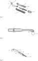
Figure 1 illustrates a perspective of the dental matrix band -
Figure 2 illustrates a perspective exploded view of the primary parts of a dental matrix band with two deflector pushbuttons. -
Figure 3 illustrates perspective exploded view of the primary parts for second embodiment of a dental matrix band with one deflector pushbutton. -
Figure 4 illustrates a side view of a dental matrix band. -
Figure 5 illustrates an exploded view of the band and tensioning mechanism. -
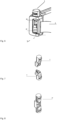
Figure 6 illustrates a section view of the band and deflector. -
Figure 7 illustrates an example of the two defector pushbuttons. -
Figure 8 illustrates an example of the single defector pushbutton. - It will be appreciated that for simplicity and clarity of illustration, elements shown in the figures have not necessarily been drawn to scale. For example, the dimensions of some of the elements may be exaggerated relative to other elements for clarity.
-
- 1-
- Housing
- 2-
- Upper Deflector Pushbutton
- 3-
- Lower Deflector Pushbutton
- 4-
- Band Control Knob
- 5-
- Band
- 6-
- Top of Housing
- 7-
- Bottom of Housing
- 8-
- Tensioning Mechanism
- 9-
- Band Loop
- 10-
- Screw Type Device
- 11-
- Front End of Housing
- 12-
- Rear End of Housing
- 13-
- Front End of Tensioning Mechanism
- 14-
- Rear End of Tensioning Mechanism
- 15-
- First Band End
- 16-
- Second Band End
- 17-
- Single Deflector Pushbutton
- 18-
- Upper Portion of Band
- 19-
- Lower Portion of Band
- 20 -
- Band Securing Mechanism
- It will be appreciated that, for simplicity and clarity of illustration, where considered appropriate, reference numerals may be repeated among the figures to indicate corresponding or analogous elements or steps. In addition, numerous specific details are set forth in order to provide a thorough understanding of the exemplary embodiments described herein. However, it will be understood by those of ordinary skill in the art, that the embodiments described herein may be practiced without these specific details. In other instances, well-known methods, procedures and components have not been described in detail so as not to obscure the embodiments described herein. Furthermore, this description is not to be considered as limiting the scope of the embodiments described herein in any way but rather as merely describing the implementation of the various embodiments described herein.
- In all embodiments and configurations the terms "coupled", "coupling", "attached", "attachment", or variants thereof as used herein can have several different meanings depending in the context in which these terms are used. For example, the terms coupled, coupling, attached, or attachment can have a mechanical connotation. For example, as used herein, the terms coupled, coupling, attached, or attachment can indicate that two elements or devices are directly connected to one another or connected to one another through one or more intermediate elements or devices via a mechanical element depending on the particular context.
- The assembled dental matrix band device shown on
Figure 1 depicts an elongated housing (1), an upper pushbutton deflector (2), a band (5), and a band control knob (4). As shown onFigure 2 the housing (1) typically includes a top (6) and a bottom (7) which are connected together after the internals are mounted. Mounted in the housing (1) are internals including a band (5), an upper deflector pushbutton (2), a lower deflector pushbutton (3), and a tensioning mechanism (8). A portion of the band (5) extends beyond a front end (11) of the housing (1) and forms a loop (9) designed to encircle a tooth. - In the device as shown on
Figure 2 the deflector pushbuttons (2) & (3) are mounted transversely to the longitude length of the housing (1) at the housing's front end (11). A portion of each deflector pushbutton (2, 3, & 17) extends beyond the housing (1) and a remaining portion of each deflector pushbutton is in the housing (1) adjacent to a portion of the band (5). The deflector pushbuttons are mounted such that they can apply pressure to a different portion of the band (5) depending on which pushbutton is pushed into the housing (1). Applying pressure to an upper portion (18) or a lower portion (19) (Figure 6 ) of the band (5) changes the geometry of the band to better match the geometry of the tooth. - The deflector pushbuttons can be configured with a pushbutton as an integral part of the deflector pushbutton or the pushbutton can be a separate part attached to the deflector.
Figures 6 & 7 illustrate one possible configuration of the upper deflector pushbutton and the lower deflector pushbutton, and their assembly in the housing (1). As depicted onFigures 6 & 7 the upper and lower deflector pushbuttons can be interlocked. - A tensioning mechanism (8) is provided to control the size of the loop (9) of the band (5). A band securing mechanism (20) is also provided.
Figure 2 shows as one example of a tensioning mechanism (8) a screw type device (10) attached to or configured as a part of a rear end (14) of the tensioning mechanism (8). The band (5) is provided with two ends as shown onFigure 5 with one or both ends of the band (5) connected to a front end (13) of the tensioning mechanism (8). If only one end of the band (5)) is connected to the tensioning mechanism (8) the other end of the band (5) is securely attached to the housing (1). The rear end (14) of the tensioning mechanism (8) extends out of an opening in the rear end (12) of the housing (1) and is attached to a band control knob (4). Rotation of the band control knob controls the length of the diameter of the band loop (9). - Depressing the upper deflector pushbutton (2) causes the deflector to apply pressure on an upper portion (18) of the band (5). If the lower deflector pushbutton (3) of the deflector (2) is pushed into the housing (1) it causes the deflector to apply pressure on the lower portion (19) of the band (5). Thus, the movement of the deflector pushbuttons (2), (3), and (17) creates a conical shape around the tooth due to pressure on only an upper (16) or lower (15) portion of the band (5).
- In the embodiment shown on
Figures 3 and8 a single deflector pushbutton (17) can be utilized in the dental matrix band device. The single deflector (17) can be configured with an integral pushbutton at each end of the deflector designed to extend beyond the housing or a separate pushbutton piece can be attached to each end of the deflector and designed to extend beyond the housing (1). The single deflector pushbutton applies a pressure to an upper portion of the band or to a lower portion of the band depending on which end of the single deflector pushbutton (17) is inserted into the housing (1). Both the single pushbutton deflector (17) embodiment and the two pushbutton deflectors (2 & 3) embodiment have the same functionality as disclosed and illustrated. - One embodiment of the Dental Matrix Band includes:
A housing with a top, a bottom, a front end, and a rear end; a band with two ends mounted in the housing with a portion of the band extending beyond the front end of the housing and forms a loop designed to encircle a tooth. An upper deflector pushbutton is mounted transversely to a longitudinal length of the housing. A portion of the upper deflector pushbutton extends beyond the top of the housing, and a portion of the upper deflector pushbutton is positioned adjacent to the band and designed to change a geometry of the band by applying pressure to a portion of the band. - A lower deflector pushbutton is mounted transversely to a longitudinal length of the housing. A portion of the lower deflector pushbutton extends beyond the bottom of the housing, and a portion of the lower deflector pushbutton is positioned adjacent to the band and designed to change a geometry of the band by applying pressure to a portion of the band.
- A tensioning mechanism is attached to the band and designed to control the length of a diameter of the loop extending beyond the front end of the housing. Another embodiment includes:
A housing with a top, a bottom, a front end and a rear end; a band with two ends mounted in the housing with a portion of the band extending beyond the front end of the housing and forming a loop designed to encircle a tooth. A single deflector pushbutton with a first end and a second end is mounted transversely to a longitudinal length of the housing. The first end of the deflector pushbutton extends beyond the top of the housing and the second end of the deflector pushbutton extends beyond the bottom of the housing. A portion of the single deflector pushbutton is positioned adjacent to the band and designed to change a geometry of the band by applying pressure to a portion of the band. A tensioning mechanism is attached to the band and designed to control the length of a diameter of the loop extending beyond the front end of the housing.
Claims (9)
- A dental matrix band comprising:a housing (1) with a top (6), a bottom (7), a front end (11) and a rear end (12);a band (5) with two ends (15, 16) mounted in the housing, wherein a portion of the band extends beyond the front end of the housing and forms a loop (9) designed to encircle a tooth;an upper deflector pushbutton (2) mounted transversely to a longitudinal length of the housing, wherein a portion of the upper deflector pushbutton extends beyond the top of the housing, and a portion of the upper deflector pushbutton is positioned adjacent to the band and designed to change a geometry of the band by applying pressure to a portion of the band;a lower deflector pushbutton (3) mounted transversely to a longitudinal length of the housing, wherein a portion of the lower deflector pushbutton extends beyond the bottom of the housing, and a portion of the lower deflector pushbutton is positioned adjacent to the band and designed to change a geometry of the band by applying pressure to a portion of the band; anda tensioning mechanism (8) attached to the band and designed to control a length of the portion of the band extending beyond the front end of the housing.
- The dental matrix band according to claim 1 wherein the tensioning mechanism is attached to at least one end of the band and includes a band securing mechanism to adjust and secure a length of the band.
- The dental matrix band according to claim 1 or 2 wherein the tensioning mechanism is a screw type device and the band securing mechanism is a control knob extending beyond the rear end of the housing enabling turning of the control knob to control the length of the band by moving the screw type device.
- The dental matrix band according to any of the preceding claims wherein pushing the upper deflector pushbutton toward the housing applies pressure to an upper portion of the band creating a conical shape of the band around a tooth; and pushing the lower deflector pushbutton toward the housing applies pressure to a lower portion of the band creating a conical shape of the band around the tooth.
- The dental matrix band according to any of the preceding claims wherein the upper deflector pushbutton and the lower deflector pushbutton are interlocked together.
- A dental matrix band comprising:a housing (1) with a top (6), a bottom (7), a front end (11) and a rear end (12);a band (5) with two ends (15, 16) mounted in the housing, wherein a portion of the band extends beyond the front end of the housing and forms a loop (9) designed to encircle a tooth;a single deflector pushbutton (17) with a first end and a second end mounted transversely to a longitudinal length of the housing, wherein the first end of the single deflector pushbutton extends beyond the top of the housing and the second end of the single deflector pushbutton extends beyond the bottom of the housing, and a portion of the single deflector pushbutton is positioned adjacent to the band and designed to change a geometry of the band by applying pressure to a portion of the band; anda tensioning mechanism (8) attached to the band and designed to control the length of a diameter of the loop extending beyond the front end of the housing.
- The dental matrix band according to claim 6 wherein the tensioning mechanism is attached to at least one end of the band and includes a band securing mechanism to adjust and secure the length of the band.
- The dental matrix band according to claim 6 or 7, wherein the tensioning mechanism is a screw type device and the band securing mechanism is a band control knob extending beyond the rear end of the housing enabling turning of the band control knob to control the length of the band by moving the screw type mechanism.
- The dental matrix band according to claim any one of claims 6-8, wherein pushing the first end of the deflector pushbutton toward the housing applies pressure to an upper portion of the band creating a conical shape of the band around a tooth; and pushing the second end of the deflector pushbutton toward the housing applies pressure to a lower portion of the band creating a conical shape of the band around a tooth.
Applications Claiming Priority (1)
| Application Number | Priority Date | Filing Date | Title |
|---|---|---|---|
| US17/005,543 US11786338B2 (en) | 2020-08-28 | 2020-08-28 | Dental band device |
Publications (2)
| Publication Number | Publication Date |
|---|---|
| EP3960115A1 EP3960115A1 (en) | 2022-03-02 |
| EP3960115B1 true EP3960115B1 (en) | 2024-01-03 |
Family
ID=73288473
Family Applications (1)
| Application Number | Title | Priority Date | Filing Date |
|---|---|---|---|
| EP20206711.2A Active EP3960115B1 (en) | 2020-08-28 | 2020-11-10 | Dental matrix band device |
Country Status (10)
| Country | Link |
|---|---|
| US (2) | US11786338B2 (en) |
| EP (1) | EP3960115B1 (en) |
| JP (1) | JP7504766B2 (en) |
| KR (1) | KR20220029274A (en) |
| CN (1) | CN114099044A (en) |
| AU (1) | AU2020256443A1 (en) |
| CA (1) | CA3099641A1 (en) |
| ES (1) | ES2974365T3 (en) |
| GB (1) | GB2598414B (en) |
| PL (1) | PL3960115T3 (en) |
Families Citing this family (1)
| Publication number | Priority date | Publication date | Assignee | Title |
|---|---|---|---|---|
| KR102663284B1 (en) | 2022-12-22 | 2024-05-07 | 이마고웍스 주식회사 | Deformation method of tooth model, tooth model deformation apparatus and computer readable medium having program for performing the method |
Family Cites Families (11)
| Publication number | Priority date | Publication date | Assignee | Title |
|---|---|---|---|---|
| US2400172A (en) * | 1942-12-14 | 1946-05-14 | Columbus Dental Mfg Co | Matrix clamp |
| US2367439A (en) * | 1943-01-11 | 1945-01-16 | Orin C Samphere | Matrix retainer |
| US2560553A (en) * | 1949-03-17 | 1951-07-17 | Donald R Christie | Dental matrix clamp |
| US2964847A (en) * | 1959-08-31 | 1960-12-20 | Benjamin F Tofflemire | Combination dental appliance defining a traction instrument and detachable clamping bocks for matrix bands |
| US5055045A (en) * | 1991-03-18 | 1991-10-08 | Dickie Robert G | Disposable dental matrix retainer clamp |
| US5342197A (en) | 1994-01-19 | 1994-08-30 | Innovadent Technologies Ltd. | Dental matrix retainer clamp |
| US6234793B1 (en) | 1999-07-19 | 2001-05-22 | Ultradent Products, Inc. | Textured dental matrix bands and related methods |
| DE10240683B4 (en) | 2002-09-04 | 2005-04-14 | Alfred Schaffner | Dental matrix tensioner |
| GB0820074D0 (en) * | 2008-11-01 | 2008-12-10 | Astek Innovations Ltd | Dental matrix clamp |
| US10315107B2 (en) | 2017-08-02 | 2019-06-11 | Microsoft Technology Licensing, Llc | Controller button having a simulated axis of rotation |
| US11090136B2 (en) | 2017-08-25 | 2021-08-17 | Ultradent Products, Inc. | Dental matrix devices |
-
2020
- 2020-08-28 US US17/005,543 patent/US11786338B2/en active Active
- 2020-10-16 AU AU2020256443A patent/AU2020256443A1/en active Pending
- 2020-10-20 GB GB2016622.9A patent/GB2598414B/en active Active
- 2020-10-29 JP JP2020181733A patent/JP7504766B2/en active Active
- 2020-11-10 PL PL20206711.2T patent/PL3960115T3/en unknown
- 2020-11-10 EP EP20206711.2A patent/EP3960115B1/en active Active
- 2020-11-10 ES ES20206711T patent/ES2974365T3/en active Active
- 2020-11-13 KR KR1020200152356A patent/KR20220029274A/en not_active Withdrawn
- 2020-11-16 CA CA3099641A patent/CA3099641A1/en active Pending
- 2020-12-29 CN CN202011610618.1A patent/CN114099044A/en active Pending
-
2023
- 2023-08-24 US US18/454,875 patent/US12285308B2/en active Active
Also Published As
| Publication number | Publication date |
|---|---|
| US20230404707A1 (en) | 2023-12-21 |
| CA3099641A1 (en) | 2022-02-28 |
| GB2598414B (en) | 2024-07-17 |
| US20220061956A1 (en) | 2022-03-03 |
| JP7504766B2 (en) | 2024-06-24 |
| CN114099044A (en) | 2022-03-01 |
| GB2598414A (en) | 2022-03-02 |
| US12285308B2 (en) | 2025-04-29 |
| US11786338B2 (en) | 2023-10-17 |
| JP2022039885A (en) | 2022-03-10 |
| ES2974365T3 (en) | 2024-06-27 |
| EP3960115A1 (en) | 2022-03-02 |
| PL3960115T3 (en) | 2024-05-13 |
| AU2020256443A1 (en) | 2022-03-17 |
| KR20220029274A (en) | 2022-03-08 |
| GB202016622D0 (en) | 2020-12-02 |
Similar Documents
| Publication | Publication Date | Title |
|---|---|---|
| CN107735010B (en) | Endoscope with a detachable handle | |
| EP3337722B1 (en) | Display unit and electric bicycle | |
| US6203559B1 (en) | Method and apparatus for tissue dissection | |
| US11553833B2 (en) | Handle for an endoscope | |
| DE102004013190B4 (en) | Operating head unit for an endoscope | |
| WO2020080938A3 (en) | Steerable instrument comprising a tube element | |
| DE69508145T2 (en) | Insulation arrangement for a welded hermetic end piece | |
| US12285308B2 (en) | Dental band device | |
| JPS61131701A (en) | Foot fixation device for ski boots | |
| ES2250824T3 (en) | TOOL HOLDER INSTALLATION TOOL. | |
| EP2289589A3 (en) | Defined Deflection Structure | |
| WO2004060434A3 (en) | Deflecting catheter | |
| US20120315593A1 (en) | Adjustable orthodontic bracket | |
| CA2419688A1 (en) | Minimally-invasive medical retrieval device | |
| HK40069722A (en) | Dental band device | |
| KR20190011102A (en) | The flexible catheter with enhanced orientation wire fixation | |
| WO2018142209A1 (en) | Wire guiding component and endoscope comprising at least one pulling wire | |
| AU6481199A (en) | Needle assembly | |
| US20190307533A1 (en) | Intraoral telescoping spring | |
| WO2019162523A1 (en) | Umbrella handle and automatic umbrella with audio function | |
| DE3346296C2 (en) | Actuator for transmitting a linear movement to a switch | |
| JPH04193252A (en) | Endoscope | |
| JPS6335225A (en) | Apparatus for bending insert part of endoscope | |
| JP2663614B2 (en) | Endoscope Angle Ring Connection Pin | |
| JPH0642865B2 (en) | Endoscope |
Legal Events
| Date | Code | Title | Description |
|---|---|---|---|
| PUAI | Public reference made under article 153(3) epc to a published international application that has entered the european phase |
Free format text: ORIGINAL CODE: 0009012 |
|
| STAA | Information on the status of an ep patent application or granted ep patent |
Free format text: STATUS: THE APPLICATION HAS BEEN PUBLISHED |
|
| AK | Designated contracting states |
Kind code of ref document: A1 Designated state(s): AL AT BE BG CH CY CZ DE DK EE ES FI FR GB GR HR HU IE IS IT LI LT LU LV MC MK MT NL NO PL PT RO RS SE SI SK SM TR |
|
| STAA | Information on the status of an ep patent application or granted ep patent |
Free format text: STATUS: REQUEST FOR EXAMINATION WAS MADE |
|
| 17P | Request for examination filed |
Effective date: 20220829 |
|
| RBV | Designated contracting states (corrected) |
Designated state(s): AL AT BE BG CH CY CZ DE DK EE ES FI FR GB GR HR HU IE IS IT LI LT LU LV MC MK MT NL NO PL PT RO RS SE SI SK SM TR |
|
| GRAP | Despatch of communication of intention to grant a patent |
Free format text: ORIGINAL CODE: EPIDOSNIGR1 |
|
| STAA | Information on the status of an ep patent application or granted ep patent |
Free format text: STATUS: GRANT OF PATENT IS INTENDED |
|
| RIC1 | Information provided on ipc code assigned before grant |
Ipc: A61C 5/85 20170101AFI20230519BHEP |
|
| P01 | Opt-out of the competence of the unified patent court (upc) registered |
Effective date: 20230526 |
|
| INTG | Intention to grant announced |
Effective date: 20230616 |
|
| GRAS | Grant fee paid |
Free format text: ORIGINAL CODE: EPIDOSNIGR3 |
|
| RBV | Designated contracting states (corrected) |
Designated state(s): AL AT BE BG CH CY CZ DE DK EE ES FI FR GR HR HU IE IS IT LI LT LU LV MC MK MT NL NO PL PT RO RS SE SI SK SM TR |
|
| GRAA | (expected) grant |
Free format text: ORIGINAL CODE: 0009210 |
|
| STAA | Information on the status of an ep patent application or granted ep patent |
Free format text: STATUS: THE PATENT HAS BEEN GRANTED |
|
| AK | Designated contracting states |
Kind code of ref document: B1 Designated state(s): AL AT BE BG CH CY CZ DE DK EE ES FI FR GR HR HU IE IS IT LI LT LU LV MC MK MT NL NO PL PT RO RS SE SI SK SM TR |
|
| REG | Reference to a national code |
Ref country code: CH Ref legal event code: EP |
|
| REG | Reference to a national code |
Ref country code: DE Ref legal event code: R096 Ref document number: 602020023743 Country of ref document: DE |
|
| REG | Reference to a national code |
Ref country code: IE Ref legal event code: FG4D |
|
| REG | Reference to a national code |
Ref country code: NL Ref legal event code: FP |
|
| REG | Reference to a national code |
Ref country code: LT Ref legal event code: MG9D |
|
| REG | Reference to a national code |
Ref country code: AT Ref legal event code: MK05 Ref document number: 1646033 Country of ref document: AT Kind code of ref document: T Effective date: 20240103 |
|
| REG | Reference to a national code |
Ref country code: ES Ref legal event code: FG2A Ref document number: 2974365 Country of ref document: ES Kind code of ref document: T3 Effective date: 20240627 |
|
| PG25 | Lapsed in a contracting state [announced via postgrant information from national office to epo] |
Ref country code: IS Free format text: LAPSE BECAUSE OF FAILURE TO SUBMIT A TRANSLATION OF THE DESCRIPTION OR TO PAY THE FEE WITHIN THE PRESCRIBED TIME-LIMIT Effective date: 20240503 |
|
| PG25 | Lapsed in a contracting state [announced via postgrant information from national office to epo] |
Ref country code: LT Free format text: LAPSE BECAUSE OF FAILURE TO SUBMIT A TRANSLATION OF THE DESCRIPTION OR TO PAY THE FEE WITHIN THE PRESCRIBED TIME-LIMIT Effective date: 20240103 |
|
| PG25 | Lapsed in a contracting state [announced via postgrant information from national office to epo] |
Ref country code: GR Free format text: LAPSE BECAUSE OF FAILURE TO SUBMIT A TRANSLATION OF THE DESCRIPTION OR TO PAY THE FEE WITHIN THE PRESCRIBED TIME-LIMIT Effective date: 20240404 |
|
| PG25 | Lapsed in a contracting state [announced via postgrant information from national office to epo] |
Ref country code: HR Free format text: LAPSE BECAUSE OF FAILURE TO SUBMIT A TRANSLATION OF THE DESCRIPTION OR TO PAY THE FEE WITHIN THE PRESCRIBED TIME-LIMIT Effective date: 20240103 Ref country code: RS Free format text: LAPSE BECAUSE OF FAILURE TO SUBMIT A TRANSLATION OF THE DESCRIPTION OR TO PAY THE FEE WITHIN THE PRESCRIBED TIME-LIMIT Effective date: 20240403 |
|
| PG25 | Lapsed in a contracting state [announced via postgrant information from national office to epo] |
Ref country code: AT Free format text: LAPSE BECAUSE OF FAILURE TO SUBMIT A TRANSLATION OF THE DESCRIPTION OR TO PAY THE FEE WITHIN THE PRESCRIBED TIME-LIMIT Effective date: 20240103 Ref country code: CZ Free format text: LAPSE BECAUSE OF FAILURE TO SUBMIT A TRANSLATION OF THE DESCRIPTION OR TO PAY THE FEE WITHIN THE PRESCRIBED TIME-LIMIT Effective date: 20240103 |
|
| PG25 | Lapsed in a contracting state [announced via postgrant information from national office to epo] |
Ref country code: RS Free format text: LAPSE BECAUSE OF FAILURE TO SUBMIT A TRANSLATION OF THE DESCRIPTION OR TO PAY THE FEE WITHIN THE PRESCRIBED TIME-LIMIT Effective date: 20240403 Ref country code: NO Free format text: LAPSE BECAUSE OF FAILURE TO SUBMIT A TRANSLATION OF THE DESCRIPTION OR TO PAY THE FEE WITHIN THE PRESCRIBED TIME-LIMIT Effective date: 20240403 Ref country code: LT Free format text: LAPSE BECAUSE OF FAILURE TO SUBMIT A TRANSLATION OF THE DESCRIPTION OR TO PAY THE FEE WITHIN THE PRESCRIBED TIME-LIMIT Effective date: 20240103 Ref country code: IS Free format text: LAPSE BECAUSE OF FAILURE TO SUBMIT A TRANSLATION OF THE DESCRIPTION OR TO PAY THE FEE WITHIN THE PRESCRIBED TIME-LIMIT Effective date: 20240503 Ref country code: HR Free format text: LAPSE BECAUSE OF FAILURE TO SUBMIT A TRANSLATION OF THE DESCRIPTION OR TO PAY THE FEE WITHIN THE PRESCRIBED TIME-LIMIT Effective date: 20240103 Ref country code: GR Free format text: LAPSE BECAUSE OF FAILURE TO SUBMIT A TRANSLATION OF THE DESCRIPTION OR TO PAY THE FEE WITHIN THE PRESCRIBED TIME-LIMIT Effective date: 20240404 Ref country code: CZ Free format text: LAPSE BECAUSE OF FAILURE TO SUBMIT A TRANSLATION OF THE DESCRIPTION OR TO PAY THE FEE WITHIN THE PRESCRIBED TIME-LIMIT Effective date: 20240103 Ref country code: BG Free format text: LAPSE BECAUSE OF FAILURE TO SUBMIT A TRANSLATION OF THE DESCRIPTION OR TO PAY THE FEE WITHIN THE PRESCRIBED TIME-LIMIT Effective date: 20240103 Ref country code: AT Free format text: LAPSE BECAUSE OF FAILURE TO SUBMIT A TRANSLATION OF THE DESCRIPTION OR TO PAY THE FEE WITHIN THE PRESCRIBED TIME-LIMIT Effective date: 20240103 |
|
| PG25 | Lapsed in a contracting state [announced via postgrant information from national office to epo] |
Ref country code: PT Free format text: LAPSE BECAUSE OF FAILURE TO SUBMIT A TRANSLATION OF THE DESCRIPTION OR TO PAY THE FEE WITHIN THE PRESCRIBED TIME-LIMIT Effective date: 20240503 |
|
| PG25 | Lapsed in a contracting state [announced via postgrant information from national office to epo] |
Ref country code: SE Free format text: LAPSE BECAUSE OF FAILURE TO SUBMIT A TRANSLATION OF THE DESCRIPTION OR TO PAY THE FEE WITHIN THE PRESCRIBED TIME-LIMIT Effective date: 20240103 Ref country code: PT Free format text: LAPSE BECAUSE OF FAILURE TO SUBMIT A TRANSLATION OF THE DESCRIPTION OR TO PAY THE FEE WITHIN THE PRESCRIBED TIME-LIMIT Effective date: 20240503 Ref country code: LV Free format text: LAPSE BECAUSE OF FAILURE TO SUBMIT A TRANSLATION OF THE DESCRIPTION OR TO PAY THE FEE WITHIN THE PRESCRIBED TIME-LIMIT Effective date: 20240103 |
|
| REG | Reference to a national code |
Ref country code: DE Ref legal event code: R097 Ref document number: 602020023743 Country of ref document: DE |
|
| PG25 | Lapsed in a contracting state [announced via postgrant information from national office to epo] |
Ref country code: DK Free format text: LAPSE BECAUSE OF FAILURE TO SUBMIT A TRANSLATION OF THE DESCRIPTION OR TO PAY THE FEE WITHIN THE PRESCRIBED TIME-LIMIT Effective date: 20240103 |
|
| PG25 | Lapsed in a contracting state [announced via postgrant information from national office to epo] |
Ref country code: SM Free format text: LAPSE BECAUSE OF FAILURE TO SUBMIT A TRANSLATION OF THE DESCRIPTION OR TO PAY THE FEE WITHIN THE PRESCRIBED TIME-LIMIT Effective date: 20240103 |
|
| PG25 | Lapsed in a contracting state [announced via postgrant information from national office to epo] |
Ref country code: EE Free format text: LAPSE BECAUSE OF FAILURE TO SUBMIT A TRANSLATION OF THE DESCRIPTION OR TO PAY THE FEE WITHIN THE PRESCRIBED TIME-LIMIT Effective date: 20240103 |
|
| PG25 | Lapsed in a contracting state [announced via postgrant information from national office to epo] |
Ref country code: SK Free format text: LAPSE BECAUSE OF FAILURE TO SUBMIT A TRANSLATION OF THE DESCRIPTION OR TO PAY THE FEE WITHIN THE PRESCRIBED TIME-LIMIT Effective date: 20240103 |
|
| PG25 | Lapsed in a contracting state [announced via postgrant information from national office to epo] |
Ref country code: SM Free format text: LAPSE BECAUSE OF FAILURE TO SUBMIT A TRANSLATION OF THE DESCRIPTION OR TO PAY THE FEE WITHIN THE PRESCRIBED TIME-LIMIT Effective date: 20240103 Ref country code: SK Free format text: LAPSE BECAUSE OF FAILURE TO SUBMIT A TRANSLATION OF THE DESCRIPTION OR TO PAY THE FEE WITHIN THE PRESCRIBED TIME-LIMIT Effective date: 20240103 Ref country code: RO Free format text: LAPSE BECAUSE OF FAILURE TO SUBMIT A TRANSLATION OF THE DESCRIPTION OR TO PAY THE FEE WITHIN THE PRESCRIBED TIME-LIMIT Effective date: 20240103 Ref country code: EE Free format text: LAPSE BECAUSE OF FAILURE TO SUBMIT A TRANSLATION OF THE DESCRIPTION OR TO PAY THE FEE WITHIN THE PRESCRIBED TIME-LIMIT Effective date: 20240103 Ref country code: DK Free format text: LAPSE BECAUSE OF FAILURE TO SUBMIT A TRANSLATION OF THE DESCRIPTION OR TO PAY THE FEE WITHIN THE PRESCRIBED TIME-LIMIT Effective date: 20240103 |
|
| PLBE | No opposition filed within time limit |
Free format text: ORIGINAL CODE: 0009261 |
|
| STAA | Information on the status of an ep patent application or granted ep patent |
Free format text: STATUS: NO OPPOSITION FILED WITHIN TIME LIMIT |
|
| 26N | No opposition filed |
Effective date: 20241007 |
|
| PG25 | Lapsed in a contracting state [announced via postgrant information from national office to epo] |
Ref country code: SI Free format text: LAPSE BECAUSE OF FAILURE TO SUBMIT A TRANSLATION OF THE DESCRIPTION OR TO PAY THE FEE WITHIN THE PRESCRIBED TIME-LIMIT Effective date: 20240103 |
|
| REG | Reference to a national code |
Ref country code: CH Ref legal event code: PL |
|
| REG | Reference to a national code |
Ref country code: CH Ref legal event code: PL |
|
| PG25 | Lapsed in a contracting state [announced via postgrant information from national office to epo] |
Ref country code: CH Free format text: LAPSE BECAUSE OF NON-PAYMENT OF DUE FEES Effective date: 20241130 |
|
| PG25 | Lapsed in a contracting state [announced via postgrant information from national office to epo] |
Ref country code: FI Free format text: LAPSE BECAUSE OF FAILURE TO SUBMIT A TRANSLATION OF THE DESCRIPTION OR TO PAY THE FEE WITHIN THE PRESCRIBED TIME-LIMIT Effective date: 20240103 |
|
| PG25 | Lapsed in a contracting state [announced via postgrant information from national office to epo] |
Ref country code: IE Free format text: LAPSE BECAUSE OF NON-PAYMENT OF DUE FEES Effective date: 20241110 |
|
| PGFP | Annual fee paid to national office [announced via postgrant information from national office to epo] |
Ref country code: LU Payment date: 20251119 Year of fee payment: 6 Ref country code: NL Payment date: 20251119 Year of fee payment: 6 |
|
| PGFP | Annual fee paid to national office [announced via postgrant information from national office to epo] |
Ref country code: DE Payment date: 20251119 Year of fee payment: 6 |
|
| PGFP | Annual fee paid to national office [announced via postgrant information from national office to epo] |
Ref country code: MC Payment date: 20251121 Year of fee payment: 6 |
|
| PGFP | Annual fee paid to national office [announced via postgrant information from national office to epo] |
Ref country code: IT Payment date: 20251125 Year of fee payment: 6 |
|
| PGFP | Annual fee paid to national office [announced via postgrant information from national office to epo] |
Ref country code: FR Payment date: 20251126 Year of fee payment: 6 |
|
| PGFP | Annual fee paid to national office [announced via postgrant information from national office to epo] |
Ref country code: BE Payment date: 20251119 Year of fee payment: 6 |
|
| PGFP | Annual fee paid to national office [announced via postgrant information from national office to epo] |
Ref country code: PL Payment date: 20251022 Year of fee payment: 6 |
|
| PGFP | Annual fee paid to national office [announced via postgrant information from national office to epo] |
Ref country code: ES Payment date: 20251229 Year of fee payment: 6 |
|
| PG25 | Lapsed in a contracting state [announced via postgrant information from national office to epo] |
Ref country code: HU Free format text: LAPSE BECAUSE OF FAILURE TO SUBMIT A TRANSLATION OF THE DESCRIPTION OR TO PAY THE FEE WITHIN THE PRESCRIBED TIME-LIMIT; INVALID AB INITIO Effective date: 20201110 |
|
| PG25 | Lapsed in a contracting state [announced via postgrant information from national office to epo] |
Ref country code: CY Free format text: LAPSE BECAUSE OF FAILURE TO SUBMIT A TRANSLATION OF THE DESCRIPTION OR TO PAY THE FEE WITHIN THE PRESCRIBED TIME-LIMIT; INVALID AB INITIO Effective date: 20201110 |