EP3960090B1 - Two-probe wireless ultrasonic device, control method therefor, and control system thereof - Google Patents
Two-probe wireless ultrasonic device, control method therefor, and control system thereof Download PDFInfo
- Publication number
- EP3960090B1 EP3960090B1 EP19926005.0A EP19926005A EP3960090B1 EP 3960090 B1 EP3960090 B1 EP 3960090B1 EP 19926005 A EP19926005 A EP 19926005A EP 3960090 B1 EP3960090 B1 EP 3960090B1
- Authority
- EP
- European Patent Office
- Prior art keywords
- probe
- ultrasonic
- antenna
- dual
- sets
- Prior art date
- Legal status (The legal status is an assumption and is not a legal conclusion. Google has not performed a legal analysis and makes no representation as to the accuracy of the status listed.)
- Active
Links
Images

Classifications
-
- A—HUMAN NECESSITIES
- A61—MEDICAL OR VETERINARY SCIENCE; HYGIENE
- A61B—DIAGNOSIS; SURGERY; IDENTIFICATION
- A61B8/00—Diagnosis using ultrasonic, sonic or infrasonic waves
- A61B8/44—Constructional features of the ultrasonic, sonic or infrasonic diagnostic device
- A61B8/4477—Constructional features of the ultrasonic, sonic or infrasonic diagnostic device using several separate ultrasound transducers or probes
-
- A—HUMAN NECESSITIES
- A61—MEDICAL OR VETERINARY SCIENCE; HYGIENE
- A61B—DIAGNOSIS; SURGERY; IDENTIFICATION
- A61B8/00—Diagnosis using ultrasonic, sonic or infrasonic waves
- A61B8/44—Constructional features of the ultrasonic, sonic or infrasonic diagnostic device
- A61B8/4444—Constructional features of the ultrasonic, sonic or infrasonic diagnostic device related to the probe
- A61B8/4455—Features of the external shape of the probe, e.g. ergonomic aspects
-
- A—HUMAN NECESSITIES
- A61—MEDICAL OR VETERINARY SCIENCE; HYGIENE
- A61B—DIAGNOSIS; SURGERY; IDENTIFICATION
- A61B8/00—Diagnosis using ultrasonic, sonic or infrasonic waves
- A61B8/44—Constructional features of the ultrasonic, sonic or infrasonic diagnostic device
- A61B8/4444—Constructional features of the ultrasonic, sonic or infrasonic diagnostic device related to the probe
- A61B8/4472—Wireless probes
-
- A—HUMAN NECESSITIES
- A61—MEDICAL OR VETERINARY SCIENCE; HYGIENE
- A61B—DIAGNOSIS; SURGERY; IDENTIFICATION
- A61B8/00—Diagnosis using ultrasonic, sonic or infrasonic waves
- A61B8/54—Control of the diagnostic device
-
- A—HUMAN NECESSITIES
- A61—MEDICAL OR VETERINARY SCIENCE; HYGIENE
- A61B—DIAGNOSIS; SURGERY; IDENTIFICATION
- A61B8/00—Diagnosis using ultrasonic, sonic or infrasonic waves
- A61B8/56—Details of data transmission or power supply
Definitions
- the present application relates to the field of medical ultrasonic diagnostic imaging, and particularly to a dual-probe wireless ultrasonic device, a control method and a control system thereof.
- the dual-probe ultrasonic device includes: two sets of ultrasonic probes provided on a probe body and having different installation positions, a control board respectively connected to the two sets of ultrasonic probes and provided inside the probe body, and a communication device for transmitting images.
- USB cable is usually connected to the outside of the probe body to connect with an external communication device for image transmission.
- the communication device is an antenna which can transmit wireless signals to communicate with external devices and then transmit images.
- the dual-probe wireless ultrasonic device there are mainly two manners to install the antenna in the prior art.
- One is to install the antenna on an ultrasonic probe side.
- This installation manner is subject to requirements of synchronization signal transmission of the ultrasonic probe.
- the installation of the antenna on the ultrasonic probe side may affect the image quality.
- the other manner is to install the antenna on a main body housing. For this solution of installing the antenna on the main body housing, if the user holds the probe body during use, the antenna signal transmission is also affected.
- the document CN 101366662 A discloses a multi-headed imaging probe and an imaging system using the same.
- the diagnostic imaging system that includes an image acquisition component, a transmitter operatively coupled to the image acquisition component to transmit a signal therefrom, and a beamformer operatively coupled to the image acquisition component to receive image data therefrom.
- a processor configured to assemble images from the acquired image data and a display configured to display the images.
- the image acquisition component includes a multi-headed probe that has a plurality of transducers configured to permit a change of active transducers during an imaging session without a change of the image acquisition component.
- the document CN 101742968 A discloses a wireless ultrasound probe having a probe case enclosing a transducer array, a probe controller, and a transceiver which wirelessly receives control signals from and transmits image signals to a host system.
- a liquid-tight user interface including basic probe user controls such as directional controls, an image freeze control, and an image save control.
- the user interface may be fabricated as a touch panel LCD or OLED display.
- the probe may alternatively be controlled by a separate user interface which wirelessly transmits control signals to the host system or the probe. Either user interface may also include a display such as battery charge and signal strength indicators.
- the present application provides a dual-probe wireless ultrasonic device, a control method and a control system thereof.
- a dual-probe wireless ultrasonic device including: two sets of ultrasonic probes arranged on a probe body and having different installation positions, and a control board communicatively connected with the two sets of ultrasonic probes respectively and arranged inside the probe body;
- the dual-probe wireless ultrasonic device further includes: two sets of antennas for data transmission and communicatively connected with the control board;
- the two sets of ultrasonic probes comprise: a first ultrasonic probe and a second ultrasonic probe;
- the two sets of antennas comprising: a first antenna arranged on the second ultrasonic probe and communicatively connected with the first ultrasonic probe, and a second antenna arranged on the first ultrasonic probe and communicatively connected with the second ultrasonic probe.
- a material of the probe body is a metal material and/or a plastic material.
- the two sets of ultrasonic probes are respectively arranged at two opposite end portions of the probe body.
- At least one of the two sets of antennas is arranged away from the probe body.
- each ultrasonic probe includes: a housing configured to receive a functional component of the ultrasonic probe, and at least one of the two sets of antennas is arranged adjacent to an inner wall surface of the housing.
- At least one of the two sets of antennas is arranged on the inner wall surface of the housing.
- At least one of the two sets of antennas is glued and fixed on the inner wall surface of the housing, or fixed on the inner wall surface of the housing in a snap-fit manner.
- the dual-probe wireless ultrasonic device further includes: a battery arranged inside the probe body.
- a method for controlling a dual-probe wireless ultrasonic device of the above embodiment including:
- a system for controlling a dual-probe wireless ultrasonic device of the above embodiment including:
- the present application has the beneficial effects that: the dual-probe wireless ultrasonic device of the present application can wirelessly support the operation of dual-acoustic probes, and when any probe operates, the transmission of the probe signal is not interfered, thereby achieving an image with a better quality.
- the antennas include: a first antenna 71 provided on the second ultrasonic probe 33 and communicatively connected with the first ultrasonic probe 31, and a second antenna 73 provided on the first ultrasonic probe 31 and communicatively connected with the second ultrasonic probe 33.
- the two sets of antennas are arranged away from the probe body 10, to increase a distance between the corresponding ultrasonic probe and the antenna as far as possible to ensure the communication effect.
- the first ultrasonic probe 31 includes a housing 311 configured to receive a functional component of the first ultrasonic probe;
- the second ultrasonic probe 33 includes a housing 331 configured to receive a functional component of the second ultrasonic probe;
- the materials of the housings (311, 331) are all plastic materials.
- the two sets of antennas can be selectively arranged inside the corresponding ultrasonic probes respectively.
- the functional component is, for example, a transducer, etc., which is not described in detail here.
- the two sets of antennas (71, 73) can be selectively arranged adjacent to inner wall surfaces of the corresponding housings (331, 311) respectively.
- the two sets of antennas (71, 73) can be selectively arranged on the inner wall surfaces of the corresponding housings (331, 311) respectively.
- the two sets of antennas (71, 73) can be fixed on the inner wall surfaces of the corresponding housings (331, 311) respectively in a variety of ways, for example, can be glued and fixed on the inner wall surfaces of the housings respectively, or fixed on the inner wall surfaces of the housings respectively in a snap-fit manner, which will not be described in detail here.
- the first antenna 71 is glued and fixed on the inner wall surface of the housing 331 of the second ultrasonic probe 33, and is arranged adjacent to the housing 331 and away from the end portion of the probe body 10.
- the second antenna is glued and fixed on the inner wall surface of the housing 311 of the first ultrasonic probe 31, and is arranged adjacent to the housing 311 and away from the end portion of the probe body 10.
- the first antenna 71 and the second antenna 73 are both communicatively connected with the control board 50 through a cable, and the control board 50 controls the conductions of the two sets of antennas during the operation of the dual-probe wireless ultrasonic device.
- the specific conduction process will be described in detail below.
- the dual-probe wireless ultrasonic device further includes: a battery 90 arranged inside the probe body.
- the battery 90 is configured to provide power to the entire device to satisfy various application scenarios, which will not be detailed here.
- a method for controlling a dual-probe wireless ultrasonic device as described above includes: if the first ultrasonic probe is monitored and activated, the first antenna is turned on while the second antenna is turned off; if the second ultrasonic probe is monitored and activated, the second antenna is turned on while the first antenna is turned off; the first antenna is arranged on the second ultrasonic probe, and the second antenna is arranged on the first ultrasonic probe.
- the second antenna arranged thereon is automatically turned off, and the first antenna which is away from the first ultrasonic probe and is arranged on the second ultrasonic probe is activated; when the second ultrasonic probe operates, the first antenna arranged thereon is automatically turned off, and the second antenna which is away from the second ultrasonic probe and is arranged on the first ultrasonic probe is activated; thus, it can be ensured that each ultrasonic probe is not interfered by a signal from the antenna arranged thereon when operating; at the same time, because the antenna is arranged on the ultrasonic probe, the user can also hold any position on the probe body when using the wireless ultrasonic device, which is convenient for the user to operate.
- the present application also provides a system for controlling a dual-probe wireless ultrasonic device as described above, the system includes: an operation state monitoring module 100 and a control conversion module 200.
- the working status monitoring module 100 is configured to monitor a currently activated ultrasonic probe in real time after the dual-probe wireless ultrasonic device is turned on.
- the control conversion module 200 is configured to control turn-on of the antenna through the activated ultrasonic probe; if the first ultrasonic probe is monitored and activated, the first antenna is turned on while the second antenna is turned off; if the second ultrasonic probe is monitored and activated, the second antenna is turned on while the first antenna is turned off.
- the first antenna is arranged on the second ultrasonic probe, and the second antenna is arranged on the first ultrasonic probe.
- the dual-probe wireless ultrasonic device in the present application can wirelessly support dual-acoustic probe operation; and when any probe operates, the transmission of the probe signal is not interfered, thereby obtaining images with a higher quality.
Landscapes
- Health & Medical Sciences (AREA)
- Life Sciences & Earth Sciences (AREA)
- Engineering & Computer Science (AREA)
- Heart & Thoracic Surgery (AREA)
- Molecular Biology (AREA)
- Biophysics (AREA)
- Nuclear Medicine, Radiotherapy & Molecular Imaging (AREA)
- Pathology (AREA)
- Radiology & Medical Imaging (AREA)
- Biomedical Technology (AREA)
- Veterinary Medicine (AREA)
- Medical Informatics (AREA)
- Physics & Mathematics (AREA)
- Surgery (AREA)
- Animal Behavior & Ethology (AREA)
- General Health & Medical Sciences (AREA)
- Public Health (AREA)
- Computer Networks & Wireless Communication (AREA)
- Gynecology & Obstetrics (AREA)
- Ultra Sonic Daignosis Equipment (AREA)
Description
- The present application relates to the field of medical ultrasonic diagnostic imaging, and particularly to a dual-probe wireless ultrasonic device, a control method and a control system thereof.
- The dual-probe ultrasonic device is a medical device manufactured based on the principle of ultrasound, which is used in conjunction with an ultrasonic machine and is configured to transmit and receive ultrasonic waves during the ultrasonic detection process. A dual-probe wireless ultrasonic device usually includes two probes. The types of the two probes can be the same or different. The type of the probe includes, for example, a linear array probe, an arc array probe, and a phased array probe.
- The dual-probe ultrasonic device includes: two sets of ultrasonic probes provided on a probe body and having different installation positions, a control board respectively connected to the two sets of ultrasonic probes and provided inside the probe body, and a communication device for transmitting images.
- In the prior art, a USB cable is usually connected to the outside of the probe body to connect with an external communication device for image transmission. With the increase in user demands, the demand for dual-probe wireless ultrasonic devices has become more widespread. In this device, the communication device is an antenna which can transmit wireless signals to communicate with external devices and then transmit images.
- For the dual-probe wireless ultrasonic device, there are mainly two manners to install the antenna in the prior art. One is to install the antenna on an ultrasonic probe side. This installation manner is subject to requirements of synchronization signal transmission of the ultrasonic probe. The installation of the antenna on the ultrasonic probe side may affect the image quality. The other manner is to install the antenna on a main body housing. For this solution of installing the antenna on the main body housing, if the user holds the probe body during use, the antenna signal transmission is also affected.
- The document
CN 101366662 A discloses a multi-headed imaging probe and an imaging system using the same. Specifically provided is the diagnostic imaging system that includes an image acquisition component, a transmitter operatively coupled to the image acquisition component to transmit a signal therefrom, and a beamformer operatively coupled to the image acquisition component to receive image data therefrom. Also included is a processor configured to assemble images from the acquired image data and a display configured to display the images. The image acquisition component includes a multi-headed probe that has a plurality of transducers configured to permit a change of active transducers during an imaging session without a change of the image acquisition component. - The document
CN 101742968 A discloses a wireless ultrasound probe having a probe case enclosing a transducer array, a probe controller, and a transceiver which wirelessly receives control signals from and transmits image signals to a host system. Mounted on the probe case is a liquid-tight user interface including basic probe user controls such as directional controls, an image freeze control, and an image save control. The user interface may be fabricated as a touch panel LCD or OLED display. The probe may alternatively be controlled by a separate user interface which wirelessly transmits control signals to the host system or the probe. Either user interface may also include a display such as battery charge and signal strength indicators. - The present application provides a dual-probe wireless ultrasonic device, a control method and a control system thereof.
- In order to achieve the above application purposes, a dual-probe wireless ultrasonic device is provided in an embodiment of the present application, including: two sets of ultrasonic probes arranged on a probe body and having different installation positions, and a control board communicatively connected with the two sets of ultrasonic probes respectively and arranged inside the probe body;
- the dual-probe wireless ultrasonic device further includes: two sets of antennas for data transmission and communicatively connected with the control board;
- the two sets of ultrasonic probes comprise: a first ultrasonic probe and a second ultrasonic probe;
- the two sets of antennas comprising: a first antenna arranged on the second ultrasonic probe and communicatively connected with the first ultrasonic probe, and a second antenna arranged on the first ultrasonic probe and communicatively connected with the second ultrasonic probe.
- As an improvement of an embodiment of the present application, a material of the probe body is a metal material and/or a plastic material.
- As an improvement of an embodiment of the present application, the two sets of ultrasonic probes are respectively arranged at two opposite end portions of the probe body.
- As an improvement of an embodiment of the present application, at least one of the two sets of antennas is arranged away from the probe body.
- As an improvement of an embodiment of the present application, each ultrasonic probe includes: a housing configured to receive a functional component of the ultrasonic probe, and at least one of the two sets of antennas is arranged adjacent to an inner wall surface of the housing.
- As an improvement of an embodiment of the present application, at least one of the two sets of antennas is arranged on the inner wall surface of the housing.
- As an improvement of an embodiment of the present application, at least one of the two sets of antennas is glued and fixed on the inner wall surface of the housing, or fixed on the inner wall surface of the housing in a snap-fit manner.
- As an improvement of an embodiment of the present application, the dual-probe wireless ultrasonic device further includes: a battery arranged inside the probe body.
- In order to achieve the above invention purposes, a method for controlling a dual-probe wireless ultrasonic device of the above embodiment is provided in an embodiment of the present application, including:
- monitoring a currently activated ultrasonic probe of the first and second ultrasonic probes in real time after turning on the dual-probe wireless ultrasonic device;
- if the first ultrasonic probe is monitored and activated, turning on a first antenna and turning off a second antenna;
- if the second ultrasonic probe is monitored and activated, turning on the second antenna and turning off the first antenna.
- In order to achieve the above invention purposes, a system for controlling a dual-probe wireless ultrasonic device of the above embodiment is provided in an embodiment of the present application, including:
- an operation status monitoring module, configured to monitor a currently activated ultrasonic probe of the first and second ultrasonic probes in real time after the dual-probe wireless ultrasonic device is turned on;
- a control conversion module, configured to control turn-on of an antenna of the first and second antennas through the activated ultrasonic probe;
- if the first ultrasonic probe is monitored and activated, a first antenna is turned on and a second antenna is turned off;
- if the second ultrasonic probe is monitored and activated, the second antenna is turned on and the first antenna is turned off.
- Compared to the prior art, the present application has the beneficial effects that: the dual-probe wireless ultrasonic device of the present application can wirelessly support the operation of dual-acoustic probes, and when any probe operates, the transmission of the probe signal is not interfered, thereby achieving an image with a better quality.
-
-
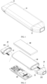
FIG. 1 is a schematic diagram illustrating an overall structure of a dual-probe wireless ultrasonic device. -
FIG. 2 is a schematic diagram illustrating an exploded structure ofFIG. 1 . -
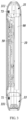
FIG. 3 is a cross-sectional view ofFIG. 1 . -
FIG. 4 is a schematic flowchart showing a method for controlling a dual-probe wireless ultrasonic device according to an embodiment of the present application. -
FIG. 5 is a schematic diagram illustrating modules of a system for controlling a dual-probe wireless ultrasonic device according to an embodiment of the present application. - The present application will be described in detail with reference to specific embodiments shown in accompanying drawings. However, these embodiments do not limit the present application; and transformations in the structure, method, or function made by those skilled in the art based on these embodiments are all included in the protection scope of the present application.
- Referring to
FIGS. 1-3 , a dual-probe wireless ultrasonic device is provided in an embodiment of the present application, which includes: two sets of ultrasonic probes provided on aprobe body 10 and having different installation positions, acontrol board 50 respectively communicatively connected with the two sets of ultrasonic probes and provided inside theprobe body 10, and two sets of antennas for a data transmission and communicatively connected with thecontrol board 50. The ultrasonic probes include a firstultrasonic probe 31 and a secondultrasonic probe 33 provided at different positions on theprobe body 10. The antennas include: afirst antenna 71 provided on the secondultrasonic probe 33 and communicatively connected with the firstultrasonic probe 31, and asecond antenna 73 provided on the firstultrasonic probe 31 and communicatively connected with the secondultrasonic probe 33. - It should be noted that the types of the first
ultrasonic probe 31 and the secondultrasonic probe 33 can be the same or different, which can be both one of a linear array probe, an arc array probe, and a phased array probe. In a specific implementation of the present application, the firstultrasonic probe 31 is an arc array probe, and the secondultrasonic probe 33 is a phased array probe. - In an embodiment of the present application, since the antenna is provided by avoiding the
probe body 10, a material of theprobe body 10 does not need to be limited, which can be, for example, ABS, PC, plastic, metal, etc. In a preferred embodiment of the present application, the material of theprobe body 10 is a metal material and/or a plastic material. Therefore, when the dual-probe wireless ultrasonic device has a requirement to ground, and the material of theprobe body 10 is set to the metal or electroplating within a plastic housing, etc., without screening the transmission of the antenna signal. - Correspondingly, in a preferred embodiment of the present application, the material of the
probe body 10 is the metal material. In such a manner, while meeting the requirement of grounding the dual-probe wireless ultrasonic device, the product can be made lighter and thinner, and has a certain texture. Further, the transmission of the antenna signal is not affected either. - In embodiments of the present application, the positions of the two probes are not specifically limited. For example, the two ultrasonic probes are arranged at an acute angle, a right angle, or an obtuse angle between them. In a preferred embodiment of the present application, the two sets of ultrasonic probes are respectively arranged at two opposite end portions of the
probe body 10. - In embodiments of the present application, the installation position of any set of antennas corresponding to the ultrasonic probe can be freely selected, for example, can be arranged on the outside and/or inside of the ultrasonic probe.
- It should be appreciated that, for each ultrasonic probe, the farther away the antenna communicatively connected with the ultrasonic probe, the better the communication effect. In a preferred embodiment of the present application, the two sets of antennas are arranged away from the
probe body 10, to increase a distance between the corresponding ultrasonic probe and the antenna as far as possible to ensure the communication effect. - In a preferred implementation of the present application, the first
ultrasonic probe 31 includes ahousing 311 configured to receive a functional component of the first ultrasonic probe; the secondultrasonic probe 33 includes ahousing 331 configured to receive a functional component of the second ultrasonic probe; the materials of the housings (311, 331) are all plastic materials. Preferably, the two sets of antennas can be selectively arranged inside the corresponding ultrasonic probes respectively. The functional component is, for example, a transducer, etc., which is not described in detail here. - In an embodiment of the present application, the two sets of antennas (71, 73) can be selectively arranged adjacent to inner wall surfaces of the corresponding housings (331, 311) respectively.
- In a further embodiment of the present application, the two sets of antennas (71, 73) can be selectively arranged on the inner wall surfaces of the corresponding housings (331, 311) respectively.
- In a specific embodiment of the present application, the two sets of antennas (71, 73) can be fixed on the inner wall surfaces of the corresponding housings (331, 311) respectively in a variety of ways, for example, can be glued and fixed on the inner wall surfaces of the housings respectively, or fixed on the inner wall surfaces of the housings respectively in a snap-fit manner, which will not be described in detail here.
- In a specific embodiment of the present application, the
first antenna 71 is glued and fixed on the inner wall surface of thehousing 331 of the secondultrasonic probe 33, and is arranged adjacent to thehousing 331 and away from the end portion of theprobe body 10. The second antenna is glued and fixed on the inner wall surface of thehousing 311 of the firstultrasonic probe 31, and is arranged adjacent to thehousing 311 and away from the end portion of theprobe body 10. - In addition, in a preferred embodiment of the present application, the
first antenna 71 and thesecond antenna 73 are both communicatively connected with thecontrol board 50 through a cable, and thecontrol board 50 controls the conductions of the two sets of antennas during the operation of the dual-probe wireless ultrasonic device. The specific conduction process will be described in detail below. - In a preferred embodiment of the present application, the dual-probe wireless ultrasonic device further includes: a
battery 90 arranged inside the probe body. Thebattery 90 is configured to provide power to the entire device to satisfy various application scenarios, which will not be detailed here. - As shown in
FIG. 4 , in an embodiment of the present application, a method for controlling a dual-probe wireless ultrasonic device as described above is provided. The method includes: if the first ultrasonic probe is monitored and activated, the first antenna is turned on while the second antenna is turned off; if the second ultrasonic probe is monitored and activated, the second antenna is turned on while the first antenna is turned off; the first antenna is arranged on the second ultrasonic probe, and the second antenna is arranged on the first ultrasonic probe. In this way, when the first ultrasonic probe operates, the second antenna arranged thereon is automatically turned off, and the first antenna which is away from the first ultrasonic probe and is arranged on the second ultrasonic probe is activated; when the second ultrasonic probe operates, the first antenna arranged thereon is automatically turned off, and the second antenna which is away from the second ultrasonic probe and is arranged on the first ultrasonic probe is activated; thus, it can be ensured that each ultrasonic probe is not interfered by a signal from the antenna arranged thereon when operating; at the same time, because the antenna is arranged on the ultrasonic probe, the user can also hold any position on the probe body when using the wireless ultrasonic device, which is convenient for the user to operate. - As shown in
FIG. 5 , the present application also provides a system for controlling a dual-probe wireless ultrasonic device as described above, the system includes: an operationstate monitoring module 100 and acontrol conversion module 200. The workingstatus monitoring module 100 is configured to monitor a currently activated ultrasonic probe in real time after the dual-probe wireless ultrasonic device is turned on. Thecontrol conversion module 200 is configured to control turn-on of the antenna through the activated ultrasonic probe; if the first ultrasonic probe is monitored and activated, the first antenna is turned on while the second antenna is turned off; if the second ultrasonic probe is monitored and activated, the second antenna is turned on while the first antenna is turned off. The first antenna is arranged on the second ultrasonic probe, and the second antenna is arranged on the first ultrasonic probe. - In conclusion, the dual-probe wireless ultrasonic device in the present application can wirelessly support dual-acoustic probe operation; and when any probe operates, the transmission of the probe signal is not interfered, thereby obtaining images with a higher quality.
- It should be understood that although this specification is described in accordance with the embodiments, not each embodiment only includes one independent technical solution. This narration mode in the specification is merely for clarity, and those skilled in the art should regard the specification as a whole. The technical solutions in the embodiments can also be appropriately combined to form other embodiments that can be understood by those skilled in the art.
- The series of detailed descriptions listed above are merely specific descriptions of feasible embodiments of the present application, which are not intended to limit the scope of protection of the present application.
Claims (10)
- A dual-probe wireless ultrasonic device, comprising: two sets of ultrasonic probes arranged on a probe body (10) and having different installation positions, and a control board (50) communicatively connected with the two sets of ultrasonic probes respectively and arranged inside the probe body (10);wherein the dual-probe wireless ultrasonic device further comprises: two sets of antennas for data transmission and communicatively connected with the control board;wherein, the two sets of ultrasonic probes comprise: a first ultrasonic probe (31) and a second ultrasonic probe (33);the two sets of antennas comprising: a first antenna (71) arranged on the second ultrasonic probe (33) and communicatively connected with the first ultrasonic probe (31), and a second antenna (73) arranged on the first ultrasonic probe (31) and communicatively connected with the second ultrasonic probe (33).
- The dual-probe wireless ultrasonic device according to claim 1, wherein a material of the probe body (10) is a metal material and/or a plastic material.
- The dual-probe wireless ultrasonic device according to claim 1, wherein the two sets of ultrasonic probes are respectively arranged at two opposite end portions of the probe body (10).
- The dual-probe wireless ultrasonic device according to claim 1, wherein at least one of the two sets of antennas is arranged away from the probe body (10).
- The dual-probe wireless ultrasonic device according to claim 1, wherein each ultrasonic probe comprises: a housing (311, 331) configured to receive a functional component of the ultrasonic probe, and at least one of the two sets of antennas is arranged adjacent to an inner wall surface of the housing (311, 331).
- The dual-probe wireless ultrasonic device according to claim 5, wherein at least one of the two sets of antennas is arranged on the inner wall surface of the housing (311, 331).
- The dual-probe wireless ultrasonic device according to claim 6, wherein at least one of the two sets of antennas is glued and fixed on the inner wall surface of the housing (311, 331), or fixed on the inner wall surface of the housing (311, 331) in a snap-fit manner.
- The dual-probe wireless ultrasonic device according to claim 6, further comprising: a battery (90) arranged inside the probe body (10).
- A method for controlling a dual-probe wireless ultrasonic device according to claim 1 comprising:monitoring a currently activated ultrasonic probe of the first and second ultrasonic probes in real time after turning on the dual-probe wireless ultrasonic device;if the first ultrasonic probe is monitored and activated, turning on the first antenna and turning off the second antenna;if the second ultrasonic probe is monitored and activated, turning on the second antenna and turning off the first antenna.
- A system for controlling a dual-probe wireless ultrasonic device according to claim 1 comprising:an operation status monitoring module (100), configured to monitor a currently activated ultrasonic probe of the first and second ultrasonic probes in real time after the dual-probe wireless ultrasonic device is turned on;a control conversion module (200), configured to control turn-on of an antenna of the first and second antennas through the activated ultrasonic probe;wherein, if the first ultrasonic probe is monitored and activated, the first antenna is turned on and the second antenna is turned off;if the second ultrasonic probe is monitored and activated, the second antenna is turned on and the first antenna is turned off.
Applications Claiming Priority (2)
| Application Number | Priority Date | Filing Date | Title |
|---|---|---|---|
| CN201910335638.3A CN109893170B (en) | 2019-04-24 | 2019-04-24 | Double-probe wireless ultrasonic device, control method and control system thereof |
| PCT/CN2019/123868 WO2020215740A1 (en) | 2019-04-24 | 2019-12-09 | Two-probe wireless ultrasonic device, control method therefor, and control system thereof |
Publications (3)
| Publication Number | Publication Date |
|---|---|
| EP3960090A1 EP3960090A1 (en) | 2022-03-02 |
| EP3960090A4 EP3960090A4 (en) | 2023-01-11 |
| EP3960090B1 true EP3960090B1 (en) | 2025-01-08 |
Family
ID=66956406
Family Applications (1)
| Application Number | Title | Priority Date | Filing Date |
|---|---|---|---|
| EP19926005.0A Active EP3960090B1 (en) | 2019-04-24 | 2019-12-09 | Two-probe wireless ultrasonic device, control method therefor, and control system thereof |
Country Status (3)
| Country | Link |
|---|---|
| EP (1) | EP3960090B1 (en) |
| CN (1) | CN109893170B (en) |
| WO (1) | WO2020215740A1 (en) |
Families Citing this family (4)
| Publication number | Priority date | Publication date | Assignee | Title |
|---|---|---|---|---|
| CN109893170B (en) * | 2019-04-24 | 2021-02-09 | 飞依诺科技(苏州)有限公司 | Double-probe wireless ultrasonic device, control method and control system thereof |
| CN111616742B (en) * | 2020-06-30 | 2025-01-03 | 广州索诺星信息科技有限公司 | A double-head multifunctional probe-type B-ultrasound instrument |
| CN112603365B (en) * | 2020-12-18 | 2025-01-07 | 无锡祥生医疗科技股份有限公司 | Switchable ultrasound probes and ultrasound equipment |
| EP4434469B1 (en) | 2023-03-22 | 2025-11-12 | Samsung Medison Co., Ltd. | Wireless probe |
Family Cites Families (7)
| Publication number | Priority date | Publication date | Assignee | Title |
|---|---|---|---|---|
| US20100160786A1 (en) * | 2007-06-01 | 2010-06-24 | Koninklijke Philips Electronics N.V. | Wireless Ultrasound Probe User Interface |
| US8043221B2 (en) * | 2007-08-17 | 2011-10-25 | General Electric Company | Multi-headed imaging probe and imaging system using same |
| CN201629739U (en) * | 2010-02-04 | 2010-11-10 | 华为终端有限公司 | Switching device and wireless terminal |
| TW201328206A (en) * | 2011-12-30 | 2013-07-01 | Fih Hong Kong Ltd | Wireless communication device |
| CN106999149B (en) * | 2014-11-25 | 2020-09-29 | 皇家飞利浦有限公司 | Multi-sensor ultrasound probe and related methods |
| CN105147323A (en) * | 2015-10-14 | 2015-12-16 | 苏州斯科特医学影像科技有限公司 | Medical wireless WIFI transmission B-mode ultrasound equipment |
| CN109893170B (en) * | 2019-04-24 | 2021-02-09 | 飞依诺科技(苏州)有限公司 | Double-probe wireless ultrasonic device, control method and control system thereof |
-
2019
- 2019-04-24 CN CN201910335638.3A patent/CN109893170B/en active Active
- 2019-12-09 EP EP19926005.0A patent/EP3960090B1/en active Active
- 2019-12-09 WO PCT/CN2019/123868 patent/WO2020215740A1/en not_active Ceased
Also Published As
| Publication number | Publication date |
|---|---|
| EP3960090A1 (en) | 2022-03-02 |
| EP3960090A4 (en) | 2023-01-11 |
| CN109893170A (en) | 2019-06-18 |
| CN109893170B (en) | 2021-02-09 |
| WO2020215740A1 (en) | 2020-10-29 |
Similar Documents
| Publication | Publication Date | Title |
|---|---|---|
| EP3960090A1 (en) | Two-probe wireless ultrasonic device, control method therefor, and control system thereof | |
| US12508005B2 (en) | Multi-purpose ultrasound image acquisition device | |
| EP3666194B1 (en) | Wireless ultrasound probe pairing with a mobile ultrasound system | |
| CN102551798B (en) | Wireless ultrasound diagnostic system | |
| JP5761829B2 (en) | Underwater communication system | |
| US6364839B1 (en) | Ultrasound diagnostic instrument having software in detachable scanhead | |
| EP3415095B1 (en) | Doppler fetus heart meter | |
| US20090043204A1 (en) | Hand-held ultrasound imaging device having removable transducer arrays | |
| EP2510880A1 (en) | Ultrasound diagnostic system | |
| US20030181811A1 (en) | Diagnostic information generation apparatus and ultrasonic diagnostic system | |
| CN106073819A (en) | Medical diagnosis imaging ultrasound probe battery group radio | |
| US20160320474A1 (en) | Transducer having surface mounted elements and associated methods | |
| KR20100057341A (en) | Ultrasound system capable of wireless communication | |
| CN102415904A (en) | Ultrasound probe | |
| CN111220969B (en) | Land networking training and performance testing integrated device of underwater communication sonar | |
| JP2009038606A (en) | Image forming apparatus | |
| JP7680894B2 (en) | Ultrasound probes and wireless ultrasound probes | |
| CN218512633U (en) | Portable mechanical scanning fish finding sonar equipment | |
| JP4806582B2 (en) | Wireless ultrasonic diagnostic equipment | |
| CN221926619U (en) | Distributed reconfigurable through-wall radar detection system | |
| CN213750325U (en) | Radar equipment, mobile platforms and drones | |
| EP3664717B1 (en) | Connectors for ultrasound imaging system | |
| KR20110130958A (en) | Transceiver for Display Devices | |
| CA2372152C (en) | Ultrasound diagnostic instrument having software in detachable scanhead | |
| CN204016336U (en) | B ultrasonic scanheads and B ultrasonic scanning system |
Legal Events
| Date | Code | Title | Description |
|---|---|---|---|
| STAA | Information on the status of an ep patent application or granted ep patent |
Free format text: STATUS: THE INTERNATIONAL PUBLICATION HAS BEEN MADE |
|
| PUAI | Public reference made under article 153(3) epc to a published international application that has entered the european phase |
Free format text: ORIGINAL CODE: 0009012 |
|
| STAA | Information on the status of an ep patent application or granted ep patent |
Free format text: STATUS: REQUEST FOR EXAMINATION WAS MADE |
|
| 17P | Request for examination filed |
Effective date: 20210923 |
|
| AK | Designated contracting states |
Kind code of ref document: A1 Designated state(s): AL AT BE BG CH CY CZ DE DK EE ES FI FR GB GR HR HU IE IS IT LI LT LU LV MC MK MT NL NO PL PT RO RS SE SI SK SM TR |
|
| DAV | Request for validation of the european patent (deleted) | ||
| DAX | Request for extension of the european patent (deleted) | ||
| A4 | Supplementary search report drawn up and despatched |
Effective date: 20221209 |
|
| RIC1 | Information provided on ipc code assigned before grant |
Ipc: A61B 8/00 20060101AFI20221205BHEP |
|
| P01 | Opt-out of the competence of the unified patent court (upc) registered |
Effective date: 20230530 |
|
| GRAP | Despatch of communication of intention to grant a patent |
Free format text: ORIGINAL CODE: EPIDOSNIGR1 |
|
| STAA | Information on the status of an ep patent application or granted ep patent |
Free format text: STATUS: GRANT OF PATENT IS INTENDED |
|
| INTG | Intention to grant announced |
Effective date: 20240801 |
|
| RIN1 | Information on inventor provided before grant (corrected) |
Inventor name: GUO, MINGKUN |
|
| GRAS | Grant fee paid |
Free format text: ORIGINAL CODE: EPIDOSNIGR3 |
|
| GRAA | (expected) grant |
Free format text: ORIGINAL CODE: 0009210 |
|
| STAA | Information on the status of an ep patent application or granted ep patent |
Free format text: STATUS: THE PATENT HAS BEEN GRANTED |
|
| AK | Designated contracting states |
Kind code of ref document: B1 Designated state(s): AL AT BE BG CH CY CZ DE DK EE ES FI FR GB GR HR HU IE IS IT LI LT LU LV MC MK MT NL NO PL PT RO RS SE SI SK SM TR |
|
| REG | Reference to a national code |
Ref country code: GB Ref legal event code: FG4D |
|
| REG | Reference to a national code |
Ref country code: CH Ref legal event code: EP |
|
| REG | Reference to a national code |
Ref country code: DE Ref legal event code: R096 Ref document number: 602019064765 Country of ref document: DE |
|
| REG | Reference to a national code |
Ref country code: IE Ref legal event code: FG4D |
|
| REG | Reference to a national code |
Ref country code: LT Ref legal event code: MG9D |
|
| REG | Reference to a national code |
Ref country code: NL Ref legal event code: MP Effective date: 20250108 |
|
| REG | Reference to a national code |
Ref country code: AT Ref legal event code: MK05 Ref document number: 1757802 Country of ref document: AT Kind code of ref document: T Effective date: 20250108 |
|
| PG25 | Lapsed in a contracting state [announced via postgrant information from national office to epo] |
Ref country code: NL Free format text: LAPSE BECAUSE OF FAILURE TO SUBMIT A TRANSLATION OF THE DESCRIPTION OR TO PAY THE FEE WITHIN THE PRESCRIBED TIME-LIMIT Effective date: 20250108 |
|
| PG25 | Lapsed in a contracting state [announced via postgrant information from national office to epo] |
Ref country code: RS Free format text: LAPSE BECAUSE OF FAILURE TO SUBMIT A TRANSLATION OF THE DESCRIPTION OR TO PAY THE FEE WITHIN THE PRESCRIBED TIME-LIMIT Effective date: 20250408 |
|
| PG25 | Lapsed in a contracting state [announced via postgrant information from national office to epo] |
Ref country code: FI Free format text: LAPSE BECAUSE OF FAILURE TO SUBMIT A TRANSLATION OF THE DESCRIPTION OR TO PAY THE FEE WITHIN THE PRESCRIBED TIME-LIMIT Effective date: 20250108 |
|
| PG25 | Lapsed in a contracting state [announced via postgrant information from national office to epo] |
Ref country code: PL Free format text: LAPSE BECAUSE OF FAILURE TO SUBMIT A TRANSLATION OF THE DESCRIPTION OR TO PAY THE FEE WITHIN THE PRESCRIBED TIME-LIMIT Effective date: 20250108 |
|
| PG25 | Lapsed in a contracting state [announced via postgrant information from national office to epo] |
Ref country code: ES Free format text: LAPSE BECAUSE OF FAILURE TO SUBMIT A TRANSLATION OF THE DESCRIPTION OR TO PAY THE FEE WITHIN THE PRESCRIBED TIME-LIMIT Effective date: 20250108 |
|
| PG25 | Lapsed in a contracting state [announced via postgrant information from national office to epo] |
Ref country code: IS Free format text: LAPSE BECAUSE OF FAILURE TO SUBMIT A TRANSLATION OF THE DESCRIPTION OR TO PAY THE FEE WITHIN THE PRESCRIBED TIME-LIMIT Effective date: 20250508 Ref country code: NO Free format text: LAPSE BECAUSE OF FAILURE TO SUBMIT A TRANSLATION OF THE DESCRIPTION OR TO PAY THE FEE WITHIN THE PRESCRIBED TIME-LIMIT Effective date: 20250408 |
|
| PG25 | Lapsed in a contracting state [announced via postgrant information from national office to epo] |
Ref country code: HR Free format text: LAPSE BECAUSE OF FAILURE TO SUBMIT A TRANSLATION OF THE DESCRIPTION OR TO PAY THE FEE WITHIN THE PRESCRIBED TIME-LIMIT Effective date: 20250108 |
|
| PG25 | Lapsed in a contracting state [announced via postgrant information from national office to epo] |
Ref country code: PT Free format text: LAPSE BECAUSE OF FAILURE TO SUBMIT A TRANSLATION OF THE DESCRIPTION OR TO PAY THE FEE WITHIN THE PRESCRIBED TIME-LIMIT Effective date: 20250508 Ref country code: LV Free format text: LAPSE BECAUSE OF FAILURE TO SUBMIT A TRANSLATION OF THE DESCRIPTION OR TO PAY THE FEE WITHIN THE PRESCRIBED TIME-LIMIT Effective date: 20250108 |
|
| PG25 | Lapsed in a contracting state [announced via postgrant information from national office to epo] |
Ref country code: GR Free format text: LAPSE BECAUSE OF FAILURE TO SUBMIT A TRANSLATION OF THE DESCRIPTION OR TO PAY THE FEE WITHIN THE PRESCRIBED TIME-LIMIT Effective date: 20250409 Ref country code: BG Free format text: LAPSE BECAUSE OF FAILURE TO SUBMIT A TRANSLATION OF THE DESCRIPTION OR TO PAY THE FEE WITHIN THE PRESCRIBED TIME-LIMIT Effective date: 20250108 |
|
| PG25 | Lapsed in a contracting state [announced via postgrant information from national office to epo] |
Ref country code: AT Free format text: LAPSE BECAUSE OF FAILURE TO SUBMIT A TRANSLATION OF THE DESCRIPTION OR TO PAY THE FEE WITHIN THE PRESCRIBED TIME-LIMIT Effective date: 20250108 |
|
| PG25 | Lapsed in a contracting state [announced via postgrant information from national office to epo] |
Ref country code: SE Free format text: LAPSE BECAUSE OF FAILURE TO SUBMIT A TRANSLATION OF THE DESCRIPTION OR TO PAY THE FEE WITHIN THE PRESCRIBED TIME-LIMIT Effective date: 20250108 |
|
| PG25 | Lapsed in a contracting state [announced via postgrant information from national office to epo] |
Ref country code: SM Free format text: LAPSE BECAUSE OF FAILURE TO SUBMIT A TRANSLATION OF THE DESCRIPTION OR TO PAY THE FEE WITHIN THE PRESCRIBED TIME-LIMIT Effective date: 20250108 |
|
| REG | Reference to a national code |
Ref country code: DE Ref legal event code: R097 Ref document number: 602019064765 Country of ref document: DE |
|
| PG25 | Lapsed in a contracting state [announced via postgrant information from national office to epo] |
Ref country code: DK Free format text: LAPSE BECAUSE OF FAILURE TO SUBMIT A TRANSLATION OF THE DESCRIPTION OR TO PAY THE FEE WITHIN THE PRESCRIBED TIME-LIMIT Effective date: 20250108 |
|
| PG25 | Lapsed in a contracting state [announced via postgrant information from national office to epo] |
Ref country code: EE Free format text: LAPSE BECAUSE OF FAILURE TO SUBMIT A TRANSLATION OF THE DESCRIPTION OR TO PAY THE FEE WITHIN THE PRESCRIBED TIME-LIMIT Effective date: 20250108 Ref country code: CZ Free format text: LAPSE BECAUSE OF FAILURE TO SUBMIT A TRANSLATION OF THE DESCRIPTION OR TO PAY THE FEE WITHIN THE PRESCRIBED TIME-LIMIT Effective date: 20250108 |
|
| PG25 | Lapsed in a contracting state [announced via postgrant information from national office to epo] |
Ref country code: RO Free format text: LAPSE BECAUSE OF FAILURE TO SUBMIT A TRANSLATION OF THE DESCRIPTION OR TO PAY THE FEE WITHIN THE PRESCRIBED TIME-LIMIT Effective date: 20250108 |
|
| PG25 | Lapsed in a contracting state [announced via postgrant information from national office to epo] |
Ref country code: SK Free format text: LAPSE BECAUSE OF FAILURE TO SUBMIT A TRANSLATION OF THE DESCRIPTION OR TO PAY THE FEE WITHIN THE PRESCRIBED TIME-LIMIT Effective date: 20250108 |
|
| PLBE | No opposition filed within time limit |
Free format text: ORIGINAL CODE: 0009261 |
|
| STAA | Information on the status of an ep patent application or granted ep patent |
Free format text: STATUS: NO OPPOSITION FILED WITHIN TIME LIMIT |
|
| 26N | No opposition filed |
Effective date: 20251009 |
|
| PGFP | Annual fee paid to national office [announced via postgrant information from national office to epo] |
Ref country code: FR Payment date: 20251230 Year of fee payment: 7 |
|
| PG25 | Lapsed in a contracting state [announced via postgrant information from national office to epo] |
Ref country code: IT Free format text: LAPSE BECAUSE OF FAILURE TO SUBMIT A TRANSLATION OF THE DESCRIPTION OR TO PAY THE FEE WITHIN THE PRESCRIBED TIME-LIMIT Effective date: 20250108 |