EP3960033B1 - Chair - Google Patents
Chair Download PDFInfo
- Publication number
- EP3960033B1 EP3960033B1 EP21187341.9A EP21187341A EP3960033B1 EP 3960033 B1 EP3960033 B1 EP 3960033B1 EP 21187341 A EP21187341 A EP 21187341A EP 3960033 B1 EP3960033 B1 EP 3960033B1
- Authority
- EP
- European Patent Office
- Prior art keywords
- chair
- transverse
- shaped
- engagement element
- resting
- Prior art date
- Legal status (The legal status is an assumption and is not a legal conclusion. Google has not performed a legal analysis and makes no representation as to the accuracy of the status listed.)
- Active
Links
- 230000008878 coupling Effects 0.000 claims description 12
- 238000010168 coupling process Methods 0.000 claims description 12
- 238000005859 coupling reaction Methods 0.000 claims description 12
- 210000001364 upper extremity Anatomy 0.000 claims description 12
- 230000000284 resting effect Effects 0.000 claims description 10
- 230000005489 elastic deformation Effects 0.000 claims description 2
- 230000000670 limiting effect Effects 0.000 description 3
- 230000010355 oscillation Effects 0.000 description 2
- 125000006850 spacer group Chemical group 0.000 description 2
- 239000000853 adhesive Substances 0.000 description 1
- 230000001070 adhesive effect Effects 0.000 description 1
- 230000001419 dependent effect Effects 0.000 description 1
- 239000000463 material Substances 0.000 description 1
- 239000007769 metal material Substances 0.000 description 1
- 230000004048 modification Effects 0.000 description 1
- 238000012986 modification Methods 0.000 description 1
- 238000003466 welding Methods 0.000 description 1
Images


Classifications
-
- A—HUMAN NECESSITIES
- A47—FURNITURE; DOMESTIC ARTICLES OR APPLIANCES; COFFEE MILLS; SPICE MILLS; SUCTION CLEANERS IN GENERAL
- A47C—CHAIRS; SOFAS; BEDS
- A47C1/00—Chairs adapted for special purposes
- A47C1/12—Theatre, auditorium, or similar chairs
- A47C1/124—Separate chairs, connectible together into a row
-
- A—HUMAN NECESSITIES
- A47—FURNITURE; DOMESTIC ARTICLES OR APPLIANCES; COFFEE MILLS; SPICE MILLS; SUCTION CLEANERS IN GENERAL
- A47C—CHAIRS; SOFAS; BEDS
- A47C3/00—Chairs characterised by structural features; Chairs or stools with rotatable or vertically-adjustable seats
- A47C3/04—Stackable chairs; Nesting chairs
-
- A—HUMAN NECESSITIES
- A47—FURNITURE; DOMESTIC ARTICLES OR APPLIANCES; COFFEE MILLS; SPICE MILLS; SUCTION CLEANERS IN GENERAL
- A47C—CHAIRS; SOFAS; BEDS
- A47C4/00—Foldable, collapsible or dismountable chairs
- A47C4/02—Dismountable chairs
- A47C4/03—Non-upholstered chairs, e.g. metal, plastic or wooden chairs
-
- A—HUMAN NECESSITIES
- A47—FURNITURE; DOMESTIC ARTICLES OR APPLIANCES; COFFEE MILLS; SPICE MILLS; SUCTION CLEANERS IN GENERAL
- A47C—CHAIRS; SOFAS; BEDS
- A47C5/00—Chairs of special materials
- A47C5/04—Metal chairs, e.g. tubular
- A47C5/10—Tubular chairs of foldable, collapsible, or dismountable type
Definitions
- the present invention relates to a chair.
- the sector to which the invention relates is the sector of chairs that are often used in waiting rooms in public and private places, meeting rooms, study rooms etc.
- chairs A are widespread, like the ones shown in Figure 1 , with a body B made of plastic material, which constitutes a seating portion and a backrest, and a metallic frame that provides the supporting legs for the body.
- a metallic frame comprises one or more tubular elements which are folded to provide two "U-shaped" parts, indicated with the letter C, which define the legs D, and a transverse portion E resting on the ground at the sides of the chair.
- a transverse element F at approximately half height or slightly lower below the seating portion, which is welded at the ends to the two front legs and is adapted to increase the stability of the chair by preventing the lateral oscillation of the legs. Examples of such known chairs are disclosed in US2012/013156A1 , DE202020002848U1 and US2017/164745A1 .
- each transverse portion anti-skid feet are attached at the corners of the U-shaped part.
- the feet on one side of the chair can be shaped so as to define a coupling for the feet on the other side of a similar chair to be placed beside and coupled to the previous chair, so as to create, with a plurality of such chairs, an aligned and orderly row.
- transverse element obstructs the freedom of movement of the user, in particular the freedom to position his/her legs, and affects the final overall weight of the chair.
- the aim of the present invention is to provide a chair that is capable of improving the known art in one or more of the above mentioned aspects.
- an object of the invention is to provide a chair that ensures at least the same level of stability as the known models of chairs while at the same time allowing a greater freedom of movement and positioning of the user's legs.
- Another object of the invention is to provide a chair frame that makes it possible to reduce the overall weight of the chair to which it is joined.
- a further object of the invention is to provide a chair that can be assembled in shorter times.
- a still further object of the present invention sets out to overcome the drawbacks of the background art in a manner that is alternative to any existing solutions.
- Another object of the invention is to provide a chair that is highly reliable, easy to implement and of low cost.
- a chair characterized in that it comprises a frame with at least two U-shaped parts, each one defining a pair of supporting legs, of which one is a front leg and the other is a rear leg, and a transverse portion for resting on the ground, the two front legs and the two rear legs being connected in an upper region by a respective transverse element and each said transverse portion of the respective U-shaped part having a section bent inward at the part resting on the ground of the respective front leg and/or of the rear leg.
- the chair according to the invention comprises a frame 20 with at least two U-shaped parts 11, each one defining a pair of supporting legs 11a, 11b, of which one is a front leg 11a and the other is a rear leg 11b, and a transverse portion 12 for resting on the ground.
- the two front legs 11a and the two rear legs 11b are connected in an upper region by a respective transverse element, 13a or 13b.
- Each transverse portion 12 of the respective U-shaped part 11 has a section 14 bent inward at the part resting on the ground of the respective front leg 11a and/or rear leg 11b.
- the section 14 is in the front part of the structure, therefore at the part resting on the ground of the front leg 11a.
- the frame 20 is constituted by one or more metallic tubular elements folded and/or welded together.
- the two U-shaped parts 11 are inclined so as to define a distance between them that increases proceeding downward from above. This makes it possible to easily stack several chairs 10 and even just frames 20.
- Each transverse portion 12 of the respective U-shaped part 11 is provided with an anti-skid covering 16 for resting on the ground.
- each chair 10 is provided with an engagement element 17a on one side and with a complementarily-shaped element 17b on the other side.
- the first engagement element 17a and the second engagement element 17b protrude from a respective anti-skid covering 16.
- the first engagement element 17a has a dovetail shape structure, while the second engagement element 17b has an opening that is shaped complementarily to the previous dovetail shape.
- the two elements are engageable by inserting the former into the latter downward from above or, conversely, the latter into the former.
- the chair 10 advantageously also comprises rapid coupling means 18 between the frame 20 and the body 15 that defines the seating portion 19 and the backrest 21 of the chair 10 itself.
- the means 18 are indicated in Figure 4 , which is an exploded view of the chair seen from below.
- These rapid coupling means 18 comprise coupling portions 22, C-shaped in cross-section, below the seating portion 19 proximate to its front and rear edges and with the opening directed downward, with respect to the position for use of the chair, and are adapted to couple with snap action, by elastic deformation, with respective transverse elements 13a and 13b of the frame 20.
- such coupling portions 22 extend longitudinally and in parallel below the seating portion 19 along its edges.
- the chair 10 conveniently also comprises a pair of plates 23 (indicated in Figure 3 and in Figure 6 ) made of metallic material, which protrude from the rear transverse element 13b, to which they are welded, on each one of which is a covering element 24 with which they are adapted to be inserted into special seats of the backrest 21 with interference.
- the covering elements 24 are thickness compensating elements and with the plates 23 they constitute a system for stiffening the backrest 21.
- knurled elements 25 to be covered with caps adapted to act as spacers in stacking chairs.
- the receptacles 26, which are also under the seating portion 19, also need to be closed with respective plugs, and also act as spacers in stacking.
- the sections 14 increase the stability of the structure by limiting their lateral oscillations, by virtue of their intermediate inclination (on the bearing plane) between the transverse portions 12 and the transverse element 13a.
- the proposed solution makes it possible to obtain the desired stability while avoiding the welding of a transverse element at approximately half-height or slightly lower below the seating portion between the two front legs.
- the stability obtained makes it possible to avoid the use of screws and of adhesive in order to affix the body to the frame, making a snap coupling between the two elements sufficient.
- the invention fully achieves the intended aim and objects by providing a chair with the same level of stability as conventional models of structures, while at the same time allowing a greater freedom of movement and of positioning of the legs for the user, while reducing the overall weight of the chair and enabling, during assembly, a rapid coupling of the body with the frame.
Description
- The present invention relates to a chair.
- The sector to which the invention relates is the sector of chairs that are often used in waiting rooms in public and private places, meeting rooms, study rooms etc.
- Among these, chairs A are widespread, like the ones shown in
Figure 1 , with a body B made of plastic material, which constitutes a seating portion and a backrest, and a metallic frame that provides the supporting legs for the body. As shown inFigure 1 , such a metallic frame comprises one or more tubular elements which are folded to provide two "U-shaped" parts, indicated with the letter C, which define the legs D, and a transverse portion E resting on the ground at the sides of the chair. Between the two U-shaped parts is a transverse element F at approximately half height or slightly lower below the seating portion, which is welded at the ends to the two front legs and is adapted to increase the stability of the chair by preventing the lateral oscillation of the legs. Examples of such known chairs are disclosed inUS2012/013156A1 ,DE202020002848U1 andUS2017/164745A1 . - Typically, on each transverse portion anti-skid feet are attached at the corners of the U-shaped part. Optionally, the feet on one side of the chair can be shaped so as to define a coupling for the feet on the other side of a similar chair to be placed beside and coupled to the previous chair, so as to create, with a plurality of such chairs, an aligned and orderly row.
- The presence of the transverse element obstructs the freedom of movement of the user, in particular the freedom to position his/her legs, and affects the final overall weight of the chair.
- Furthermore, such chairs have a further drawback in that, in order to increase their overall stability, the body needs to be joined to the frame by fixing with screws, thus requiring relatively long assembly times.
- The aim of the present invention is to provide a chair that is capable of improving the known art in one or more of the above mentioned aspects.
- Within this aim, an object of the invention is to provide a chair that ensures at least the same level of stability as the known models of chairs while at the same time allowing a greater freedom of movement and positioning of the user's legs.
- Another object of the invention is to provide a chair frame that makes it possible to reduce the overall weight of the chair to which it is joined.
- A further object of the invention is to provide a chair that can be assembled in shorter times.
- A still further object of the present invention sets out to overcome the drawbacks of the background art in a manner that is alternative to any existing solutions.
- Another object of the invention is to provide a chair that is highly reliable, easy to implement and of low cost.
- This aim and these and other objects which will become better apparent hereinafter are achieved by a chair, characterized in that it comprises a frame with at least two U-shaped parts, each one defining a pair of supporting legs, of which one is a front leg and the other is a rear leg, and a transverse portion for resting on the ground, the two front legs and the two rear legs being connected in an upper region by a respective transverse element and each said transverse portion of the respective U-shaped part having a section bent inward at the part resting on the ground of the respective front leg and/or of the rear leg.
- According to the invention, there is provided a chair as claimed in claim 1. Preferred features of the invention are set out in the dependent claims.
- Further characteristics and advantages of the invention will become better apparent from the description of a preferred, but not exclusive, embodiment of the chair according to the invention, which is illustrated by way of non-limiting example in the accompanying drawings wherein:
-
Figure 1 is a perspective view of a chair according to the prior art; -
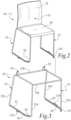
Figure 2 is a perspective view of a chair according to the present invention; -
Figure 3 is a perspective view of the frame of the chair according to the invention; -
Figure 4 is an exploded perspective view of the chair according to the invention; -
Figure 5 is a transverse cross-sectional view of a portion of chair according to the invention; -
Figure 6 is a cross-sectional view of a chair part. - With reference to the figures, the chair according to the invention, generally designated by the
reference numeral 10, comprises aframe 20 with at least twoU-shaped parts 11, each one defining a pair of supportinglegs front leg 11a and the other is arear leg 11b, and atransverse portion 12 for resting on the ground. The twofront legs 11a and the tworear legs 11b are connected in an upper region by a respective transverse element, 13a or 13b. Eachtransverse portion 12 of the respective U-shapedpart 11 has asection 14 bent inward at the part resting on the ground of the respectivefront leg 11a and/orrear leg 11b. - In the case shown, the
section 14 is in the front part of the structure, therefore at the part resting on the ground of thefront leg 11a. - The
frame 20 is constituted by one or more metallic tubular elements folded and/or welded together. - The two U-shaped
parts 11 are inclined so as to define a distance between them that increases proceeding downward from above. This makes it possible to easily stackseveral chairs 10 and even justframes 20. - Each
transverse portion 12 of the respective U-shapedpart 11 is provided with an anti-skid covering 16 for resting on the ground. - At each
transverse portion 12 of the respective U-shapedpart 11 afirst engagement element 17a protrudes outward in an intermediate region and is shaped complementarily to asecond engagement element 17b which protrudes outward in an intermediate region from atransverse portion 12 of asimilar chair 10 to be placed laterally adjacent to the preceding chair. Therefore eachchair 10 is provided with anengagement element 17a on one side and with a complementarily-shaped element 17b on the other side. - The
first engagement element 17a and thesecond engagement element 17b protrude from a respective anti-skid covering 16. - The
first engagement element 17a has a dovetail shape structure, while thesecond engagement element 17b has an opening that is shaped complementarily to the previous dovetail shape. The two elements are engageable by inserting the former into the latter downward from above or, conversely, the latter into the former. - The
chair 10 advantageously also comprises rapid coupling means 18 between theframe 20 and thebody 15 that defines theseating portion 19 and thebackrest 21 of thechair 10 itself. Themeans 18 are indicated inFigure 4 , which is an exploded view of the chair seen from below. - These rapid coupling means 18 comprise
coupling portions 22, C-shaped in cross-section, below theseating portion 19 proximate to its front and rear edges and with the opening directed downward, with respect to the position for use of the chair, and are adapted to couple with snap action, by elastic deformation, with respectivetransverse elements frame 20. - In particular,
such coupling portions 22 extend longitudinally and in parallel below theseating portion 19 along its edges. - The coupling between the
body 15 and theframe 20 is also shown in the cross-section ofFigure 5 , where it is evident that thetransverse elements - The
chair 10 conveniently also comprises a pair of plates 23 (indicated inFigure 3 and inFigure 6 ) made of metallic material, which protrude from the reartransverse element 13b, to which they are welded, on each one of which is acovering element 24 with which they are adapted to be inserted into special seats of thebackrest 21 with interference. The coveringelements 24 are thickness compensating elements and with theplates 23 they constitute a system for stiffening thebackrest 21. - Below the
seating portion 19 there are alsoknurled elements 25, to be covered with caps adapted to act as spacers in stacking chairs. Thereceptacles 26, which are also under theseating portion 19, also need to be closed with respective plugs, and also act as spacers in stacking. - Use of the chair, according to the invention, is evident from the foregoing description and, in particular, it is evident that the
sections 14 increase the stability of the structure by limiting their lateral oscillations, by virtue of their intermediate inclination (on the bearing plane) between thetransverse portions 12 and thetransverse element 13a. - It should also be noted that the proposed solution makes it possible to obtain the desired stability while avoiding the welding of a transverse element at approximately half-height or slightly lower below the seating portion between the two front legs.
- The stability obtained makes it possible to avoid the use of screws and of adhesive in order to affix the body to the frame, making a snap coupling between the two elements sufficient.
- In practice it has been found that the invention fully achieves the intended aim and objects by providing a chair with the same level of stability as conventional models of structures, while at the same time allowing a greater freedom of movement and of positioning of the legs for the user, while reducing the overall weight of the chair and enabling, during assembly, a rapid coupling of the body with the frame.
- The invention thus conceived is susceptible of numerous modifications and variations, all of which are within the scope of the appended claims.
- Where technical features mentioned in any claim are followed by reference signs, those reference signs have been included for the sole purpose of increasing the intelligibility of the claims and accordingly, such reference signs do not have any limiting effect on the interpretation of each element identified by way of example by such reference signs.
Claims (6)
- A chair (10), comprising a frame (20) with at least two U-shaped parts (11), each one defining a pair of supporting legs (11a, 11b), of which one is a front leg (11a) and the other is a rear leg (11b), and a transverse portion (12) for resting on the ground, the two front legs (11a) and the two rear legs (11b) being connected in an upper region by a respective transverse element (13a, 13b) and each said transverse portion (12) of the respective U-shaped part (11) having a section (14) bent inward at the U-shaped part (11) resting on the ground of the respective front leg (11a) and/or of the rear leg (11b), wherein the chair (10) comprises rapid coupling means (18) between said frame (20) and a body (15) that defines a seating portion (19) and a backrest (21) of said chair (10), said rapid coupling means (18) comprising coupling portions (22), C-shaped in cross-section, below said seating portion (19) proximate to its front and rear edges and with the opening directed downward, with respect to the position for use of the chair (10), wherein said coupling portions (22) are adapted to couple with snap action, by elastic deformation, with respective said transverse elements (13a, 13b).
- The chair according to claim 1, characterized in that said two U-shaped parts (11) are inclined so as to define a distance between them that increases proceeding downward from above.
- The chair according to one or more of the preceding claims, characterized in that each transverse portion (12) of the respective U-shaped part (11) is provided with an anti-skid covering (16) for resting on the ground.
- The chair according to one or more of the preceding claims, characterized in that at each transverse portion (12) of the respective U-shaped part (11) a first engagement element (17a) protrudes outward in an intermediate region and is shaped complementarily to a second engagement element (17b) which protrudes outward in an intermediate region from a transverse portion (12) of a similar chair (10) to be placed laterally adjacent to the preceding chair.
- The chair according to one or more of the preceding claims, characterized in that said first engagement element (17a) and said second engagement element (17b) each protrude from a respective said anti-skid
- The chair according to one or more of the preceding claims, characterized in that it comprises a pair of plates (23) which protrude from said rear transverse element (13b), on each one of which is a covering element (24) with which they are adapted to be inserted into adapted seats of said backrest (21).
Applications Claiming Priority (1)
| Application Number | Priority Date | Filing Date | Title |
|---|---|---|---|
| IT202000020395 | 2020-08-25 |
Publications (2)
| Publication Number | Publication Date |
|---|---|
| EP3960033A1 EP3960033A1 (en) | 2022-03-02 |
| EP3960033B1 true EP3960033B1 (en) | 2024-01-31 |
Family
ID=73139217
Family Applications (1)
| Application Number | Title | Priority Date | Filing Date |
|---|---|---|---|
| EP21187341.9A Active EP3960033B1 (en) | 2020-08-25 | 2021-07-23 | Chair |
Country Status (1)
| Country | Link |
|---|---|
| EP (1) | EP3960033B1 (en) |
Family Cites Families (3)
| Publication number | Priority date | Publication date | Assignee | Title |
|---|---|---|---|---|
| US20120013156A1 (en) * | 2010-07-14 | 2012-01-19 | Li-Chun Tsai | Frame chair for easy stacking and cascading |
| US20170164745A1 (en) * | 2015-12-15 | 2017-06-15 | Tsung-Chieh Huang | Chair without combining components |
| DE202020002848U1 (en) * | 2020-07-02 | 2020-08-03 | Dominik Kersting | Dismountable furniture with a stackable frame |
-
2021
- 2021-07-23 EP EP21187341.9A patent/EP3960033B1/en active Active
Also Published As
| Publication number | Publication date |
|---|---|
| EP3960033A1 (en) | 2022-03-02 |
Similar Documents
| Publication | Publication Date | Title |
|---|---|---|
| US3734561A (en) | Sled base frame chair | |
| US3431022A (en) | Chair construction | |
| CA1127063A (en) | Chair | |
| US2952300A (en) | Chair construction | |
| AU2010246557B2 (en) | One Piece Plastic Chair | |
| US6918632B2 (en) | Rocker mechanism for rocker recliner | |
| US7108330B2 (en) | Portable chair | |
| KR102127797B1 (en) | Frame of assembled sofa | |
| US3874726A (en) | Moulded chairs | |
| JP5518426B2 (en) | Chair with tiltable backrest | |
| KR20150004485U (en) | A cushion sit board for sofa | |
| US7216380B2 (en) | Corner guard for box spring | |
| EP3960033B1 (en) | Chair | |
| KR100972233B1 (en) | Frame chair | |
| US11006758B1 (en) | Chairback support structure | |
| EP3813594B1 (en) | Chair structure | |
| JP2019037272A (en) | Posture holder | |
| US20190281988A1 (en) | Auxiliary backrest for a chair | |
| JP6148905B2 (en) | Chair | |
| JP2010094192A (en) | Seat structure of stacking chair | |
| JP2000270962A5 (en) | ||
| JP6549370B2 (en) | Load support member for chair and chair | |
| US9986839B2 (en) | Banquet chair with outer spring | |
| JP4383788B2 (en) | Chair | |
| US7934769B1 (en) | Seat frame for folding chair |
Legal Events
| Date | Code | Title | Description |
|---|---|---|---|
| PUAI | Public reference made under article 153(3) epc to a published international application that has entered the european phase |
Free format text: ORIGINAL CODE: 0009012 |
|
| STAA | Information on the status of an ep patent application or granted ep patent |
Free format text: STATUS: THE APPLICATION HAS BEEN PUBLISHED |
|
| AK | Designated contracting states |
Kind code of ref document: A1 Designated state(s): AL AT BE BG CH CY CZ DE DK EE ES FI FR GB GR HR HU IE IS IT LI LT LU LV MC MK MT NL NO PL PT RO RS SE SI SK SM TR |
|
| STAA | Information on the status of an ep patent application or granted ep patent |
Free format text: STATUS: REQUEST FOR EXAMINATION WAS MADE |
|
| RBV | Designated contracting states (corrected) |
Designated state(s): AL AT BE BG CH CY CZ DE DK EE ES FI FR GB GR HR HU IE IS IT LI LT LU LV MC MK MT NL NO PL PT RO RS SE SI SK SM TR |
|
| 17P | Request for examination filed |
Effective date: 20220502 |
|
| GRAP | Despatch of communication of intention to grant a patent |
Free format text: ORIGINAL CODE: EPIDOSNIGR1 |
|
| STAA | Information on the status of an ep patent application or granted ep patent |
Free format text: STATUS: GRANT OF PATENT IS INTENDED |
|
| INTG | Intention to grant announced |
Effective date: 20230823 |
|
| GRAS | Grant fee paid |
Free format text: ORIGINAL CODE: EPIDOSNIGR3 |
|
| GRAA | (expected) grant |
Free format text: ORIGINAL CODE: 0009210 |
|
| STAA | Information on the status of an ep patent application or granted ep patent |
Free format text: STATUS: THE PATENT HAS BEEN GRANTED |
|
| AK | Designated contracting states |
Kind code of ref document: B1 Designated state(s): AL AT BE BG CH CY CZ DE DK EE ES FI FR GB GR HR HU IE IS IT LI LT LU LV MC MK MT NL NO PL PT RO RS SE SI SK SM TR |
|
| REG | Reference to a national code |
Ref country code: GB Ref legal event code: FG4D Ref country code: CH Ref legal event code: EP |
|
| REG | Reference to a national code |
Ref country code: DE Ref legal event code: R096 Ref document number: 602021008895 Country of ref document: DE |
|
| REG | Reference to a national code |
Ref country code: IE Ref legal event code: FG4D |
|
| U01 | Request for unitary effect filed |
Effective date: 20240226 |
|
| U07 | Unitary effect registered |
Designated state(s): AT BE BG DE DK EE FI FR IT LT LU LV MT NL PT SE SI Effective date: 20240229 |