EP3959902B1 - Systeme und verfahren zum live-streamen von notrufdaten an ersthelfer - Google Patents
Systeme und verfahren zum live-streamen von notrufdaten an ersthelfer Download PDFInfo
- Publication number
- EP3959902B1 EP3959902B1 EP20888053.4A EP20888053A EP3959902B1 EP 3959902 B1 EP3959902 B1 EP 3959902B1 EP 20888053 A EP20888053 A EP 20888053A EP 3959902 B1 EP3959902 B1 EP 3959902B1
- Authority
- EP
- European Patent Office
- Prior art keywords
- frs
- data
- location
- computing devices
- capture device
- Prior art date
- Legal status (The legal status is an assumption and is not a legal conclusion. Google has not performed a legal analysis and makes no representation as to the accuracy of the status listed.)
- Active
Links
Images


Classifications
-
- H—ELECTRICITY
- H04—ELECTRIC COMMUNICATION TECHNIQUE
- H04M—TELEPHONIC COMMUNICATION
- H04M1/00—Substation equipment, e.g. for use by subscribers
- H04M1/72—Mobile telephones; Cordless telephones, i.e. devices for establishing wireless links to base stations without route selection
- H04M1/724—User interfaces specially adapted for cordless or mobile telephones
- H04M1/72403—User interfaces specially adapted for cordless or mobile telephones with means for local support of applications that increase the functionality
- H04M1/72418—User interfaces specially adapted for cordless or mobile telephones with means for local support of applications that increase the functionality for supporting emergency services
- H04M1/72421—User interfaces specially adapted for cordless or mobile telephones with means for local support of applications that increase the functionality for supporting emergency services with automatic activation of emergency service functions, e.g. upon sensing an alarm
-
- G—PHYSICS
- G08—SIGNALLING
- G08B—SIGNALLING SYSTEMS, e.g. PERSONAL CALLING SYSTEMS; ORDER TELEGRAPHS; ALARM SYSTEMS
- G08B25/00—Alarm systems in which the location of the alarm condition is signalled to a central station, e.g. fire or police telegraphic systems
- G08B25/006—Alarm destination chosen according to type of event, e.g. in case of fire phone the fire service, in case of medical emergency phone the ambulance
-
- G—PHYSICS
- G08—SIGNALLING
- G08B—SIGNALLING SYSTEMS, e.g. PERSONAL CALLING SYSTEMS; ORDER TELEGRAPHS; ALARM SYSTEMS
- G08B25/00—Alarm systems in which the location of the alarm condition is signalled to a central station, e.g. fire or police telegraphic systems
- G08B25/01—Alarm systems in which the location of the alarm condition is signalled to a central station, e.g. fire or police telegraphic systems characterised by the transmission medium
- G08B25/08—Alarm systems in which the location of the alarm condition is signalled to a central station, e.g. fire or police telegraphic systems characterised by the transmission medium using communication transmission lines
-
- G—PHYSICS
- G10—MUSICAL INSTRUMENTS; ACOUSTICS
- G10L—SPEECH ANALYSIS TECHNIQUES OR SPEECH SYNTHESIS; SPEECH RECOGNITION; SPEECH OR VOICE PROCESSING TECHNIQUES; SPEECH OR AUDIO CODING OR DECODING
- G10L25/00—Speech or voice analysis techniques not restricted to a single one of groups G10L15/00 - G10L21/00
- G10L25/48—Speech or voice analysis techniques not restricted to a single one of groups G10L15/00 - G10L21/00 specially adapted for particular use
-
- H—ELECTRICITY
- H04—ELECTRIC COMMUNICATION TECHNIQUE
- H04L—TRANSMISSION OF DIGITAL INFORMATION, e.g. TELEGRAPHIC COMMUNICATION
- H04L65/00—Network arrangements, protocols or services for supporting real-time applications in data packet communication
- H04L65/1066—Session management
- H04L65/1076—Screening of IP real time communications, e.g. spam over Internet telephony [SPIT]
-
- H—ELECTRICITY
- H04—ELECTRIC COMMUNICATION TECHNIQUE
- H04L—TRANSMISSION OF DIGITAL INFORMATION, e.g. TELEGRAPHIC COMMUNICATION
- H04L65/00—Network arrangements, protocols or services for supporting real-time applications in data packet communication
- H04L65/60—Network streaming of media packets
- H04L65/61—Network streaming of media packets for supporting one-way streaming services, e.g. Internet radio
- H04L65/611—Network streaming of media packets for supporting one-way streaming services, e.g. Internet radio for multicast or broadcast
-
- H—ELECTRICITY
- H04—ELECTRIC COMMUNICATION TECHNIQUE
- H04L—TRANSMISSION OF DIGITAL INFORMATION, e.g. TELEGRAPHIC COMMUNICATION
- H04L65/00—Network arrangements, protocols or services for supporting real-time applications in data packet communication
- H04L65/80—Responding to QoS
-
- H—ELECTRICITY
- H04—ELECTRIC COMMUNICATION TECHNIQUE
- H04M—TELEPHONIC COMMUNICATION
- H04M3/00—Automatic or semi-automatic exchanges
- H04M3/42—Systems providing special services or facilities to subscribers
- H04M3/436—Arrangements for screening incoming calls, i.e. evaluating the characteristics of a call before deciding whether to answer it
- H04M3/4365—Arrangements for screening incoming calls, i.e. evaluating the characteristics of a call before deciding whether to answer it based on information specified by the calling party, e.g. priority or subject
-
- H—ELECTRICITY
- H04—ELECTRIC COMMUNICATION TECHNIQUE
- H04M—TELEPHONIC COMMUNICATION
- H04M3/00—Automatic or semi-automatic exchanges
- H04M3/42—Systems providing special services or facilities to subscribers
- H04M3/50—Centralised arrangements for answering calls; Centralised arrangements for recording messages for absent or busy subscribers ; Centralised arrangements for recording messages
- H04M3/51—Centralised call answering arrangements requiring operator intervention, e.g. call or contact centers for telemarketing
- H04M3/5116—Centralised call answering arrangements requiring operator intervention, e.g. call or contact centers for telemarketing for emergency applications
-
- H—ELECTRICITY
- H04—ELECTRIC COMMUNICATION TECHNIQUE
- H04M—TELEPHONIC COMMUNICATION
- H04M3/00—Automatic or semi-automatic exchanges
- H04M3/42—Systems providing special services or facilities to subscribers
- H04M3/50—Centralised arrangements for answering calls; Centralised arrangements for recording messages for absent or busy subscribers ; Centralised arrangements for recording messages
- H04M3/51—Centralised call answering arrangements requiring operator intervention, e.g. call or contact centers for telemarketing
- H04M3/523—Centralised call answering arrangements requiring operator intervention, e.g. call or contact centers for telemarketing with call distribution or queueing
- H04M3/5231—Centralised call answering arrangements requiring operator intervention, e.g. call or contact centers for telemarketing with call distribution or queueing with call back arrangements
-
- H—ELECTRICITY
- H04—ELECTRIC COMMUNICATION TECHNIQUE
- H04W—WIRELESS COMMUNICATION NETWORKS
- H04W4/00—Services specially adapted for wireless communication networks; Facilities therefor
- H04W4/02—Services making use of location information
- H04W4/021—Services related to particular areas, e.g. point of interest [POI] services, venue services or geofences
-
- H—ELECTRICITY
- H04—ELECTRIC COMMUNICATION TECHNIQUE
- H04W—WIRELESS COMMUNICATION NETWORKS
- H04W4/00—Services specially adapted for wireless communication networks; Facilities therefor
- H04W4/90—Services for handling of emergency or hazardous situations, e.g. earthquake and tsunami warning systems [ETWS]
-
- H—ELECTRICITY
- H04—ELECTRIC COMMUNICATION TECHNIQUE
- H04M—TELEPHONIC COMMUNICATION
- H04M2242/00—Special services or facilities
- H04M2242/30—Determination of the location of a subscriber
-
- H—ELECTRICITY
- H04—ELECTRIC COMMUNICATION TECHNIQUE
- H04M—TELEPHONIC COMMUNICATION
- H04M2250/00—Details of telephonic subscriber devices
- H04M2250/10—Details of telephonic subscriber devices including a GPS signal receiver
-
- H—ELECTRICITY
- H04—ELECTRIC COMMUNICATION TECHNIQUE
- H04M—TELEPHONIC COMMUNICATION
- H04M2250/00—Details of telephonic subscriber devices
- H04M2250/12—Details of telephonic subscriber devices including a sensor for measuring a physical value, e.g. temperature or motion
-
- H—ELECTRICITY
- H04—ELECTRIC COMMUNICATION TECHNIQUE
- H04W—WIRELESS COMMUNICATION NETWORKS
- H04W4/00—Services specially adapted for wireless communication networks; Facilities therefor
- H04W4/02—Services making use of location information
- H04W4/029—Location-based management or tracking services
-
- H—ELECTRICITY
- H04—ELECTRIC COMMUNICATION TECHNIQUE
- H04W—WIRELESS COMMUNICATION NETWORKS
- H04W64/00—Locating users or terminals or network equipment for network management purposes, e.g. mobility management
-
- H—ELECTRICITY
- H04—ELECTRIC COMMUNICATION TECHNIQUE
- H04W—WIRELESS COMMUNICATION NETWORKS
- H04W76/00—Connection management
- H04W76/50—Connection management for emergency connections
Definitions
- the present embodiments relate generally to relaying information to first responders (FRs), and more particularly to live streaming emergency call data to FRs.
- US 2017/0099579 A1 discloses a method and system for tracking and communicating with responders in the event of an emergency situation.
- An emergency server coupled to a wireless telecommunications network receives a notification of an emergency situation, establishes a first geofence around a location of the emergency situation, determines a set of candidate responders registered to an area associated with the location, transmits a request for user equipment (UE) locations of the set of candidate responders to a location server and receives a response, determines which UEs of candidate responders are within an area bounded by the geofence, and transmits messages soliciting responders to the UEs.
- UE user equipment
- US 2019/253861 A1 discloses an emergency response system for receiving emergency calls, capturing caller locations, and dynamically improving reported emergency caller locations, e.g. by correcting reported locations using "ground truth" test data to compensate for known location reporting device inaccuracies. It also discloses geofencing to determine emergency service providers jurisdictions, and to enable the system to process emergency calls accordingly.
- US 2014/368601 A1 discloses a method that includes: determining a location of a mobile computing device using GPS, Wi-Fi, beacon signals or other radio frequency data; identifying a plurality of candidate responders; selecting a particular candidate responder based on one or more of: user location, responder location, responder ratings, responder skills/training, type of situation, and a predefined list of responders; and initiating a two-way video chat session between the mobile computing device and the particular candidate responder over a network connection.
- Additional method examples may include: receiving, by the one or more computing devices of the one or more FRs the first signal and sending, by the one or more computing devices of the one or more FRs, the accept signal to the capture device.
- Additional method examples may include: monitoring duplicate calls associated with the emergency call.
- Additional method examples may include: displaying, on a graphical user interface (GUI) of the one or more computing devices of the one or more FRs, one or more maps comprising at least one of a location history associated with the emergency call and a current location associated with the emergency call.
- GUI graphical user interface
- a second example of the present invention provides an apparatus comprising: at least one memory; at least one processor configured to execute instructions stored in the at least one memory in order to: capture, by a capture device, an audio and location data associated with an emergency call; refine, by the capture device, the location data to provide a refined location data, wherein the refined location data comprises one or more street addresses; correlate, by the capture device, the refined location data of the emergency call with a geofenced location of one or more computing devices of one or more first responders, FRs, wherein the geofenced location is specified by the one or more FRs for their own area of coverage, thereby limiting emergency calls only to the area they are interested in, and wherein to correlate, the processor is configured to: determine by the capture device whether the refined location data of the emergency call is within a predetermined distance threshold from the geofenced location of one or more computing devices of one or more FRs for the correlation; transmit, by the capture device, a first signal to the one or more computing devices of one or more FRs based on the correlation, wherein the
- a third example of the present invention provides a computer programmable product comprising a non-transitory computer readable medium having stored thereon computer executable instruction which when executed by one or more processors, cause the one or more processors to carry out operations, the operations comprising: capturing, by a capture device, an audio and location data associated with an emergency call; refining, by the capture device, the location data to provide a refined location data, wherein the refined location data comprises one or more street addresses; correlating, by the capture device, the refined location data of the emergency call with a geofenced location of one or more computing devices of one or more first responders, FRs, wherein the geofenced location is specified by the one or more FRs for their own area of coverage, thereby limiting emergency calls only to the area they are interested in, and wherein correlating comprises determining by the capture device whether the refined location data of the emergency call is within a predetermined distance threshold from the geofenced location of one or more computing devices of one or more FRs for the correlation; transmitting, by the capture device,
- the described technology concerns one or more methods, systems, apparatuses, and mediums storing processor-executable process steps to live stream emergency call data to first responders (FRs) in the field.
- an FR can listen to a 911 emergency call in real time or live by providing the FR with all the details available to the PSAP call-taker and/or the dispatcher.
- other information would become available to the FR that would otherwise be unavailable to the FR in the field, such as tone of voice, sense of urgency, background noise, and other details the that the 911 call-taker and dispatcher may not have the time or the ability to relay to FRs in the field.
- computer-implemented instructions, data structures, screen displays, and other data related to the invention may be distributed over the Internet or other networks (including wireless networks) on a propagated signal on a propagation medium (e.g., an electromagnetic wave, a sound wave, etc.) over a period of time.
- a propagation medium e.g., an electromagnetic wave, a sound wave, etc.
- the data may be provided on any analog or digital network (e.g., packet-switched, circuit-switched, or other scheme).
- LAN Local Area Network
- WAN Wide Area Network
- program modules or subroutines may be in both local and remote memory storage devices.
- client computer e.g., PC, mobile computer, tablet, or smart phone.
- data structures and transmission of data particular to aspects of the invention are also encompassed within the scope of the described embodiments.
- FIG. 1 illustrates a high-level block diagram of a system for transmitting emergency call data to one or more FRs in the field, in accordance with an embodiment of the invention.
- the emergency call data may comprise emergency call data that is live-streamed to the one or more FRs in the field.
- the system 100 may include an FR vehicle 102, one or more FRs 104 (also referred to as FR 104 hereinafter), and a computing device 106 associated with the FR 104.
- the computing device 106 may be an in-vehicle device, a tablet, a laptop, or a mobile device, such as a smartphone.
- the computing device 106 may be magnetically mounted to the dashboard of the FR vehicle 102.
- the computing device 106 may be integrated directly into the dashboard of the FR vehicle 102.
- the FR vehicle 102 may be located within a geofence location 108.
- a geofence is a location-based service in which an application or other software that supports a global positioning system (GPS), Bluetooth, Wi-Fi, or cellular data may trigger a pre-programmed action when a mobile device or RFID tag enters or exits a virtual boundary set up around a geographical location, such as a virtual boundary around the FR vehicle 102.
- the capture device 114 may configure the geofence location 108 around the FR vehicle 102 based on GPS data received from the computing device 106 at the capture device 114.
- the geofence location 108 may be configured to allow for tracking of the FR vehicle 102.
- the control server 112 then correlates the refined incoming call information with the geofenced locations of all FRs, such as the geofence location 108 of the FR 104.
- the correlation is done based on the geofenced location 108 of the computing device 106 of the FR 104, as the computing device, 106 is configured for capturing location data, such as GPS data, of the FR 104.
- location data such as GPS data
- additional capabilities may be added to a GPS proxy to allow for multiple applications to receive GPS signals from one source.
- the system 100 may query a local server URL hosted by the GPS proxy application which can read a more accurate location from a GPS receiver to provide the location of the FR 104 and their own geofenced location 108.
- the control server 112 then directs the captured audio to an application (e.g. application 422 of FIG. 4 described below) associated with the computing device 106 of the FR 104, allowing the FR 104 to listen to the call in real-time.
- the control server 112 may also transmit the location data to a mapping function of the application associated with the computing device 106 of the FR 104.
- the control server 112 may also transmit the location data to be displayed as a table on a user interface of the computing device 106 (e.g., user interface 429 described in FIG. 4 and FIG.5 ).
- the system 100 may be configured to track usage reports associated with the use of the system 100, such as the usage data of the application 422 installed on the computing.
- the control server 112 may store a log of users using the application (e.g. application 422 of FIG. 4 described below) as a database and store it in form of a .csv file in the control server 112.
- the file may be stored in form of any other known format such as a .pdf file, Word, or Excel.
- the usage report may be used later for purpose of statistical analysis such as to determine the areas or regions where the number of accident cases is high.
- the usage report may also be used for collecting the information related to weather or reason for accidents in some embodiments.
- the usage report may be used later to measure improvements in emergency response time.
- the control server 112 may check the caller id for both the calls and consider the second call as duplicate if the caller ID for both the call are same, and thereby eliminate the duplicate call.
- the capture device 114 may screen all the incoming emergency calls and their associated metadata. The screening may be done to filter the emergency call metadata and select only emergency calls of interest or relevance to the FR 104. Thus, based on the preference set by the computing device 106 of the FR 104, only emergency call of interest may be sent to the computing device 106 of the FR 104. Such filtering helps to reduce distractions and cognitive load experienced by the FR 104.
- the system 100 may be configured to perform local storage of all the calling numbers from which the FR 104 received the call for a time period of 60 mins.
- the time period may vary and may be 45 minutes, or 2 hours depending on the different conditions and if multiple calls are within the geofence location 108 of the FR 104, all calls are displayed on the mapping function.
- the time period for viewing the calls may be configurable and can be set to any value as per user and/or dispatcher preference and requirement, without deviating from the scope of the invention.
- the system 100 may have the ability to adjust the initial playback rate of the call so that it may be played faster in the beginning to catch up with any delay before the call is played by a user, such as the FR 104. For example, if the user is listening to another call before switching to the current call, they can increase the rate of the current call to compensate for the time lag due to attending of the previous call. In a similar way, normal playback rate of the call may also adjustable if needed. This also compensates for the delay between the actual call start and the arrival and correlation of location data.
- the FR 104 can access all the features of the system 100 described above, by using the computing device 106.
- the processor 202 may be embodied in several different ways.
- the processor 202 may be embodied as one or more of various hardware processing means such as a coprocessor, a microprocessor, a controller, a digital signal processor (DSP), a processing element with or without an accompanying DSP, or various other processing circuitry including integrated circuits such as, for example, an ASIC (application specific integrated circuit), an FPGA (field programmable gate array), a microcontroller unit (MCU), a hardware accelerator, a special-purpose computer chip, or the like.
- the processor 202 may include one or more processing cores configured to perform independently.
- a multi-core processor may enable multiprocessing within a single physical package.
- the processor 202 may include one or more processors configured in tandem via the bus to enable independent execution of instructions, pipelining and/or multithreading.
- the processor 202 may be configured to provide Internet-of-Things (IoT) related capabilities to the users of the system 100, where the users may be in a vehicle, in a public area, on a highway, or walking and the like.
- IoT related capabilities may in turn be used to provide real time updates to the FRs users to take pro-active decision for helping the users.
- the system 100 may be accessed using the communication interface 212.
- Embodiments have been described with reference to flowchart illustrations and/or block diagrams of methods, apparatus (systems) and computer program products according to embodiments.
- Each block of such illustrations/diagrams, or combinations thereof, can be implemented by computer program instructions.
- the computer program instructions when provided to a processor produce a machine, such that the instructions, which execute via the processor, create means for implementing the functions/operations specified in the flowchart and/or block diagram.
- Each block in the flowchart/block diagrams may represent a hardware and/or software module or logic, implementing embodiments. In alternative implementations, the functions noted in the blocks may occur out of the order noted in the figures, concurrently, etc.
- the computer programs are stored in main memory and/or secondary memory.
- the Computer programs may also be received via a communications interface 212.
- Such computer programs when executed, enable the computer system to perform the features of the embodiments as discussed herein.
- the computer programs when executed, enable the processor and/or multi-core processor to perform the features of the computer system.
- Such computer programs represent controllers of the computer system.
- FIG. 3 illustrates a block diagram and process of an exemplary system for live streaming emergency call data to one or more FRs in the field, in accordance with an embodiment of the invention.
- the system 300 includes one or more client devices 301 such as consumer electronics devices, connected to one or more server computing systems 330.
- a server 330 includes a bus 302 or other communication mechanism for communicating information, and a processor (CPU) 304 coupled with the bus 302 for processing information.
- the server 330 also includes a main memory 306, such as a random access memory (RAM) or other dynamic storage device, coupled to the bus 302 for storing information and instructions to be executed by the processor 304.
- the main memory 306 also may be used for storing temporary variables or other intermediate information during execution or instructions to be executed by the processor 304.
- the server computer system 330 further includes a read only memory (ROM) 308 or other static storage device coupled to the bus 302 for storing static information and instructions for the processor 304.
- ROM read only memory
- a storage device 310 such as a solid state drive, magnetic disk or optical disk, is provided and coupled to the bus 302 for storing information and instructions.
- the bus 302 may contain, for example, sixty-four address lines for addressing video memory or main memory 306.
- the bus 302 can also include, for example, a 32-bit or 64-bit data bus for transferring data between and among the components, such as the CPU 304, the main memory 306, video memory and the storage 310. Alternatively, multiplex data/address lines may be used instead of separate data and address lines.
- the server 330 may be coupled via the bus 302 to a display 312 for displaying information to a computer user.
- An input device 314, including alphanumeric and other keys, is coupled to the bus 302 for communicating information and command selections to the processor 304.
- cursor control 316 such as a mouse, a trackball, or cursor direction keys for communicating direction information and command selections to the processor 304 and for controlling cursor movement on the display 312.
- the functions are performed by the processor 304 executing one or more sequences of one or more instructions contained in the main memory 306. Such instructions may be read into the main memory 306 from another computer-readable medium, such as the storage device 310. Execution of the sequences of instructions contained in the main memory 306 causes the processor 304 to perform the process steps described herein. One or more processors in a multi-processing arrangement may also be employed to execute the sequences of instructions contained in the main memory 306. In alternative embodiments, hard-wired circuitry may be used in place of or in combination with software instructions to implement the embodiments. Thus, embodiments are not limited to any specific combination of hardware circuitry and software.
- computer program medium “computer usable medium,” “computer readable medium”, and “computer program product,” are used to generally refer to media such as main memory, secondary memory, removable storage drive, a hard disk installed in hard disk drive, and signals. These computer program products are means for providing software to the computer system.
- the computer readable medium allows the computer system to read data, instructions, messages or message packets, and other computer readable information from the computer readable medium.
- the computer readable medium may include non-volatile memory, such as a floppy disk, ROM, flash memory, disk drive memory, a CD-ROM, and other permanent storage. It is useful, for example, for transporting information, such as data and computer instructions, between computer systems.
- the computer readable medium may comprise computer readable information in a transitory state medium such as a network link and/or a network interface, including a wired network or a wireless network that allow a computer to read such computer readable information.
- the computer programs also called computer control logic
- the computer programs are stored in main memory and/or secondary memory. Computer programs may also be received via a communications interface. Such computer programs, when executed, enable the computer system to perform the features of the embodiments as discussed herein. In particular, the computer programs, when executed, enable the processor multi-core processor to perform the features of the computer system. Accordingly, such computer programs represent controllers of the computer system.
- common forms of computer-readable media include, for example, a floppy disk, a flexible disk, hard disk, magnetic tape, or any other magnetic medium, a CD-ROM, any other optical medium, punch cards, paper tape, any other physical medium with patterns of holes, a RAM, a PROM, an EPROM, a FLASH-EPROM, any other memory chip or cartridge, a carrier wave as described hereinafter, or any other medium from which a computer can read.
- various forms of computer readable media may be involved in carrying one or more sequences of one or more instructions to the processor 304 for execution.
- the instructions may initially be carried on a magnetic disk of a remote computer.
- the remote computer can load the instructions into its dynamic memory and send the instructions over a telephone line using a modem.
- a modem local to the server 330 can receive the data on the telephone line and use an infrared transmitter to convert the data to an infrared signal.
- An infrared detector coupled to the bus 302 can receive the data carried in the infrared signal and place the data on the bus 302.
- the bus 302 carries the data to the main memory 306, from which the processor 304 retrieves and executes the instructions.
- the instructions received from the main memory 306 may optionally be stored on the storage device 310 either before or after execution by the processor 304.
- the server 330 (which may be equivalent to the control server 112 discussed in conjunction with Fig. 1 ) also includes a communication interface 318 coupled to the bus 302.
- the communication interface 318 provides a two-way data communication coupling to a network link 320 that is connected to the worldwide packet data communication network now commonly referred to as the Internet 328.
- the Internet 328 uses electrical, electromagnetic or optical signals that carry digital data streams.
- the signals through the various networks and the signals on the network link 320 and through the communication interface 318, which carry the digital data to and from the server 330, are exemplary forms or carrier waves transporting the information.
- the server 330 can send/receive messages and data, including e-mail, program code, through the network, the network link 320 and the communication interface 318.
- the communication interface 318 can comprise a USB/Tuner and the network link 320 may be an antenna or cable for connecting the server 330 to a cable provider, satellite provider or other terrestrial transmission system for receiving messages, data and program code from another source.
- the example versions of the embodiments described herein may be implemented as logical operations in a distributed processing system such as the system 300 including the servers 330.
- the logical operations of the embodiments may be implemented as a sequence of steps executing in the server 330, and as interconnected machine modules within the system 300.
- the implementation is a matter of choice and can depend on performance of the system 300 implementing the embodiments.
- the logical operations constituting said example versions of the embodiments are referred to for e.g., as operations, steps or modules.
- the system 300 may further include computers (e.g., personal computers, computing nodes) 305 operating in the same manner as client devices 301, where a user can utilize one or more computers 305 to manage data in the server 330.
- computers e.g., personal computers, computing nodes
- FIG. 4 illustrates an example top-level functional block diagram 400 of a computing device 420 embodiment for live streaming emergency call data to one or more FRs in the field, in accordance with an embodiment of the invention.
- the computing device 420 may be equivalent to the computing device 106 or the capture device 114 discussed in conjunction with Fig. 1 .
- the computing device 420 comprises a processor 424, such as a central processing unit (CPU), addressable memory 427, an external device interface 426, e.g., an optional universal serial bus port and related processing, and/or an Ethernet port and related processing, and an optional user interface 429, e.g., an array of status lights and one or more toggle switches, and/or a display, and/or a keyboard and/or a pointer-mouse system and/or a touch screen.
- a processor 424 such as a central processing unit (CPU), addressable memory 427, an external device interface 426, e.g., an optional universal serial bus port and related processing, and/or an Ethernet port and related processing, and an optional user interface 429, e.g., an array of status lights and one or more toggle switches, and/or a display, and/or a keyboard and/or a pointer-mouse system and/or a touch screen.
- CPU central processing unit
- external device interface 426 e.g
- the addressable memory may include any type of computer-readable media that can store data accessible by the computing device 420, such as magnetic hard and floppy disk drives, optical disk drives, magnetic cassettes, tape drives, flash memory cards, digital video disks (DVDs), Bernoulli cartridges, RAMs, ROMs, smart cards, etc.
- any medium for storing or transmitting computer-readable instructions and data may be employed, including a connection port to or node on a network, such as a LAN, WAN, or the Internet.
- these elements may be in communication with one another via a data bus 428.
- the processor 424 may be configured to execute steps of a process establishing a communication channel and processing according to the embodiments described above.
- the application 422 may have a plurality of features for better FR experience.
- the application 422 may provide for allowing the FR, such as FR 104 to rewind and re-listen to the received live-streamed emergency call for better understanding when call the quality of the received emergency call is poor.
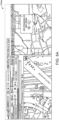
- FIGS. 5A- 5J illustrates the plurality of graphical user interfaces (GUIs) of the application associated with the computing system for live streaming emergency call data to first responders in the field, in accordance with an embodiment of the invention.
- the plurality of GUIs may be like the user interface 429 discussed in conjunction with FIG. 4 and may be accessed by the one or more FRs in the field, using their computing device 106.
- the FR 104 may be able to see the location of the 911 call on user interface 429 of computing device 420 in relationship to the FR's 104 current position on a map.
- the application 422 may have the GUI 500b as shown in FIG. 5B .
- the GUI 500b shows that the application 422 is responsive and adjustable by design, according to the type of computing device of the FR 104.
- the GUI 500b may change based on the type of device being used as the computing device 420. For example, a notification alert on mobile is different than a notification alert on a laptop.
- the present invention provides an advantage over known solutions by providing an adjustable GUI to the FR 104 based on different types of computing devices.
- FIG. 5D shows an exemplary GUI 500d, displaying a plurality of notifications that may be added to allow for background operation of the application 422 on the computing device 106 of the FR 104. This may allow the FR 104 to keep carrying on with other tasks or accessing other applications on their computing device 106, while the application 422 runs in the background. Whenever any live emergency call and its associated data is received, a notification is shown to the FR 104, who may choose to accept or dismiss the call. Thus, the application 422 will still provide alerts to the FR 104, even though it is not actively opened on their computing device 106.
- the provision of the plurality of notifications is adaptable as the instances of the application 422 grow onto different platforms.
- FIG. 5E illustrates an exemplary GUI 500e of, the application 422 that may help boost the sound levels of audio associated with incoming emergency calls.
- the GUI 500d can be helpful when there is too much ambient noise in an environment where the FR 104 is attending the call.
- the FR 104 may be able to listen in to the caller more clearly and understand their state in a better and clear manner to take the next action.
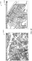
- the FRs may also specify a geofence for their own area of coverage thereby limiting calls only to the area they are interested in.
- GUI 500h1 shows setting up of a polygon as the geofence or geofence location 108 for the entire application 422.
- GUI 500h2 shows setting up of another polygon as the geofence or the geofence location 108 by the FR 104 based on defining their own area of coverage, thereby limiting calls only to the area they are interested in.
- the FRs may have the ability to customize color and opacity of geofence to make it easier to visualize calls inside/outside of the geofence.
- calls markers are colored differently based on whether they are in or out of the geofence.
- the FR 104 can choose to either hide calls outside their specified geofence location 108 or merely show them or stream them automatically.
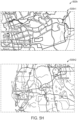
- FIG. 5I illustrates an exemplary GUI 500i in which locations of all active users of the application 422 are displayed.
- the GUI 500i may be configured to display and continuously refresh the locations of other users who are logged into the application.
- FIG. 5J illustrates an exemplary GUI 500J which provides two options to a user, a first option 500j1 to turn on a fixed location, and a second option 500j2 to turn on automatic location.
- the FR 104 may have the option to set the user's location to a fixed location on the map. This may be helpful if there is an issue in determining the exact location of the FR by all other available means. One can revert to an automatic location once GPS location determination is working again properly.
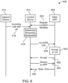
- FIG. 6 illustrates a block diagram of a process 600 for live streaming emergency call data to one or more FRs in the field, in accordance with an embodiment of the invention.
- the system 100 provides for collecting data from various sources while monitoring 911 calls for correlation and filtering of location data and other emergency response data, such as RapidSOS ® data.
- raw audio streams and other data may be relayed to FRs nearest the call in real-time.
- the user, the caller, or the calling party may be used interchangeably to mean the same, without deviating from the scope of the invention.
- a capture device 614 (equivalent to capture device 114), such as a computing device at a call center of the PSAP, captures audio data and location data associated with an incoming call.
- the location data may include the ALI data for the incoming emergency call.
- the location data is further refined, for example by querying third party databases like RapidSOS ® and ArcGIS ® , and includes additional information including the street address.
- the capture device forwards the captured data to a control server 612 (equivalent to control server 112).
- the control server 612 is also configured to receive regular location updates 620 from a web app 606 (equivalent to application 422), which may be running on the computing device 106 of one or more FRs 104 in the field. These regular location updates may include data about geofenced location 108 of the one or more computing devices 106 of one or more FRs 104 in the field.
- control server 612 of the capture device 614 is configured to transmit a first signal 622 to the one or more computing devices/ web app 606, in the form of a stream of data comprising a portion of captured audio and corresponding refined location data, such as ALI or GPS data, of the incoming emergency call.
- the one or more computing devices/ web app 606 may be configured to choose one to accept or not accept the first signal 622. If the one or more computing devices/ web app 606 accepts the first signal 622, it sends an accept signal 626 to the control server 612 of the capture device 614. The control server 612 of the capture device 614 in turn, transmits a second signal 628 to the one or more computing devices/ web app 606, which comprises a plurality of data related to the incoming emergency call.
- the data related to the incoming emergency call may be first screened, such as by the capture device 614 or the one or more computing devices /web app 606, to filter the emergency call metadata to select only emergency calls of interest or relevance to the one or more computing devices.
- This data may include, for example, emergency response data derived from RapidSOS ® data, ALI data, and GPS data related to the captured audio and corresponding location data.
- the process may end with the one or more computing devices/ web app 606 taking appropriate action based on the received data.
- the geofence such as geofence 108 around the FR's 104 current location is configurable by the control server 612 by a certain distance from the location of the FR 104 or the one or more computing devices/ web app 606. In one embodiment, the distance is a radial distance from the location of the FR 104.
- Other geofence 108 configurations are possible and contemplated, such as a rectangular-shaped geofence, a square-shaped geofence, and the like.
- the location information of the FR 104 is periodically transmitted to the control server 612 via signal 620, so long as the FR 104 stays logged into the application 606 on the computing device 106.
- the capture device 614 may determine both the calling (and the called) party associated with each incoming call to the PSAP 110.
- the calling and the called party may be determined through a Session Initiation Protocol (SIP).
- SIP Session Initiation Protocol
- IP Internet Protocol
- the capture device 614 may further determine the call circuit or "trunk" utilizing the SIP.
- the capture device 614 may determine the caller GPS location utilizing Automatic Location Identification (ALI) data and RapidSOS ® data.
- ALI Automatic Location Identification
- ALI Automatic Location Identification
- ALI may be an enhanced electronic location system that automatically relays a caller's address when they call into the PSAP 110, whether they call from a mobile device or a landline.
- the RapidSOS ® data may be configured in the control server 612, a third-party application, or on the user interface of the computing device 106.
- RapidSOS ® may link data from the calling party to the PSAP 110 and the FR 104.
- the RapidSOS ® feature may provide more precise and accurate GPS coordinates of the calling party and display the same in the user interface of the computing device 106.
- the RapidSOS ® may provide live updates when the caller is moving, and the call is in progress.
- RapidSOS ® integration is enabled, the data available for any given call from RapidSOS ® and is displayed to the user on demand.
- the RapidSOS ® data may also contain medical data as well. The medical data may be used while in an emergency to know the medical history of the user.
- the capture device 614 may transmit the signal 616 of the ALI data to the control server 612.
- the control server 612 may then determine 618 where the ALI data is to be transmitted. More specifically, the control server 612 may determine which FR (or FRs) within a geofenced area is to receive the real-time ALI data, where the geofenced area is determined by the control server 612. Furthermore, the control server 612 may determine the caller street address utilizing the ALI. The control server 612 may determine more precise street address by means of additional queries to an ArcGIS-like geocoding service When the 911 call arrives at the PSAP 110, the capture device 6114 captures the audio as well as location data associated with the call.
- the control server 612 correlates the incoming call information with the geofenced locations of all FRs, such as geofence 108 associated with the FR 104.
- the control server 612 then transmits the first signal 622 of the captured audio to the FR's 104 application on the computing device 106 so that the FR 104 may hear the call as it occurs in real-time. If the FR 104 accepts the incoming streaming data, an accept signal 626 is sent from the computing device 106 to the control server 112. After that, the second signal 628 which includes at least one of the ALI data and the GPS data of the emergency location, and the first signal 622 of the captured audio data are transmitted to the FR 104 based on the FR 104 determining whether or not to accept 624 the incoming streaming data.
- the application 606 may store the Calling Number of 911 calls and the application may then allow calls to that Called Number. Such rules prevent ordinary or "Administrative" calls from being offered to the FRs6
- the FR 104 may transmit the signal 630 from the computing device or application 606 to the control server 612 to end the process.
- FIG. 7 illustrates a schematic of an alternative system for live streaming emergency call data to first responders in the field, in accordance with an embodiment of the invention.
- the features of system 100 are retained throughout, with the system 700 further including a drone 132 associated with a geofence 138 of FIG. 1 .
- a Drone as First Responder (DFR) program may provide for setting the geofencing range.
- the drone 132 may be associated with a remote site 140.
- the remote site 140 may have a controller 142 that may set the geofence 138.
- the geofence 138 size set by the controller 142 is to be the maximum distance that the drone 132 may travel.
- the drone 132 may travel a maximum distance "d". In one embodiment, the maximum distance is three nautical miles.
- the maximum distance is greater than three miles. In yet another embodiment, the maximum distance is less than three miles. That distance "d" and the location of the remote site 140 may be determined by the capture device 114 based on a signal transmitted by the controller 142. Meanwhile, the FRs 104 are periodically transmitting the FR's location data to the control server 112. The control server 112 may then determine which FRs are within the geofence range 138 set by the drone's 132 maximum travel distance "d". The control server may then proceed to transmitting signal 122 of the captured emergency call audio to the FR's application on the computing device 106 so that the FR, such as FR 104 may hear the call as it occurs in real-time.
- the drone 132 may be able to provide streaming of information about the emergency call, such as in the form of a streaming video or image application, to the FR 104.
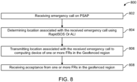
- FIG. 8 illustrates a flow diagram of working of the system 100 for live streaming emergency call data to first responders in the field, in accordance with an embodiment of the invention.
- each block of the flow diagram of the method 800 may be implemented by various means, such as hardware, firmware, processor, circuitry, and/or other communication devices associated with the execution of software including one or more computer program instructions.
- one or more of the procedures described above may be embodied by computer program instructions.
- the computer program instructions which embody the procedures described above may be stored by a memory of the system, employing an embodiment of the present invention and executed by a processor.
- any such computer program instructions may be loaded onto a computer or other programmable apparatus (for example, hardware) to produce a machine, such that the resulting computer or other programmable apparatus implements the functions specified in the flow diagram blocks.
- These computer program instructions may also be stored in a computer-readable memory that may direct a computer or other programmable apparatus to function in a particular manner, such that the instructions stored in the computer-readable memory produce an article of manufacture the execution of which implements the function specified in the flowchart blocks.
- the computer program instructions may also be loaded onto a computer or other programmable apparatus to cause a series of operations to be performed on the computer or other programmable apparatus to produce a computer-implemented process such that the instructions which execute on the computer or other programmable apparatus provide operations for implementing the functions specified in the flow diagram blocks.
- blocks of the flow diagram support combinations of means for performing the specified functions and combinations of operations for performing the specified functions for performing the specified functions. It will also be understood that one or more blocks of the flow diagram, and combinations of blocks in the flow diagram, may be implemented by special purpose hardware-based computer systems which perform the specified functions, or combinations of special purpose hardware and computer instructions.
- the system 100 may receive an emergency call on PSAP.
- the emergency call may be associated with any person in need of help. That may be related to medical help, or domestic help, accident-related help, and the like.
- the system 100 determines the location associated with the received emergency call using emergency response data, ALI data, GPS data, or a combination thereof associated with the incoming emergency call.
- the emergency response data may be RapidSOS ® data.
- the system 100 transmits location associated with the received emergency call to the computing device of one or more FRs in the geofenced region.
- the system 100 receives acceptance from one or more FRs in the geofenced region, and the assistance is provided by the FR.
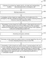
- FIG.9 illustrates a flow diagram of a system 900 for live streaming emergency call data to first responders in the field, in accordance with an embodiment of the invention.
- each block of the flow diagram of the method 900 may be implemented by various means, such as hardware, firmware, processor, circuitry, and/or other communication devices associated with the execution of software including one or more computer program instructions.
- one or more of the procedures described above may be embodied by computer program instructions.
- the computer program instructions which embody the procedures described above may be stored by a memory of the system, employing an embodiment of the present invention and executed by a processor.
- any such computer program instructions may be loaded onto a computer or other programmable apparatus (for example, hardware) to produce a machine, such that the resulting computer or other programmable apparatus implements the functions specified in the flow diagram blocks.
- These computer program instructions may also be stored in a computer-readable memory that may direct a computer or other programmable apparatus to function in a particular manner, such that the instructions stored in the computer-readable memory produce an article of manufacture the execution of which implements the function specified in the flowchart blocks.
- the computer program instructions may also be loaded onto a computer or other programmable apparatus to cause a series of operations to be performed on the computer or other programmable apparatus to produce a computer-implemented process such that the instructions which execute on the computer or other programmable apparatus provide operations for implementing the functions specified in the flow diagram blocks.
- the method 900 comprises capturing, by a capture device, an audio and corresponding location data associated with an emergency call.
- the method 900 comprises refining the location data, to provide refined location data.
- the refined location data includes more precise location data, including one or more street addresses associated with the emergency call.
- This refined location data may be obtained by sending additional queries to a RapidSOS ® like data clearinghouse, and even more precise street address may be obtained by means of additional queries to an ArcGIS ® like geocoding service.
- the method 900 comprises, correlating, by the capture device, the refined location data of the emergency call with a geofenced location of one or more computing devices of one or more first responders (FRs), such as the computing device 106 of the FR 104.
- FRs first responders
- the method 900 comprises screening the emergency call metadata.
- the screening may be done by any of the computing device 106 or the capture device 114.
- the purpose of screening is to filter the emergency call metadata so that only those emergency calls may be selected for response which are either of interest, or relevance, the one or more FRs 104. This further helps in reducing distractions and cognitive load experienced by the one or more FRs 104.
- the method 900 comprises receiving, by the capture device, an accept signal from the one or more computing devices 106 of one or more FRs 104.
- the accept signal is received in response to screening of the emergency call metadata done previously.
- the method 900 comprises transmitting, by the capture device 114, a second signal to the one or more computing devices 106 of one or more FRs 104 based on the received accept signal, wherein the second signal comprises emergency response data, Automatic Location Identification (ALI) data, global positioning system (GPS) data relating to the captured audio and corresponding refined location data, or a combination thereof.
- ALI Automatic Location Identification
- GPS global positioning system
- the one or more FRs 104 can identify the emergency caller, their requirement, their location and time to reach them based on all the data transmitted by the capture device 114. This helps in saving a lot of time in responding to the emergency calls by the suitable FR 104.
- FIG. 10 depicts a cloud computing environment 1000 for implementing an embodiment of the system and process disclosed herein, in accordance with an embodiment of the invention.
- cloud computing environment 50 comprises one or more cloud computing nodes 10 with which local computing devices used by cloud consumers, such as, for example, personal digital assistant (PDA), smartphone, smartwatch, set-top box, video game system, tablet, mobile computing device, or cellular telephone 54A, desktop computer 54B, laptop computer 54C, and/or automobile computer system 54N may communicate.
- Nodes 10 may communicate with one another. They may be grouped (not shown) physically or virtually, in one or more networks, such as Private, Community, Public, or Hybrid clouds as described hereinabove, or a combination thereof.
- cloud computing environment 50 to offer infrastructure, platforms and/or software as services for which a cloud consumer does not need to maintain resources on a local computing device. It is understood that the types of computing devices 54A-N shown in FIG. 10 are intended to be illustrative only and that computing nodes 10 and cloud computing environment 50 can communicate with any type of computerized device over any type of network and/or network addressable connection (e.g., using a web browser). Cloud computing environments are offered by Amazon, Microsoft and Google. On premises Virtualized environments may also be used, such as VMWare or Hyper-V.
Landscapes
- Engineering & Computer Science (AREA)
- Signal Processing (AREA)
- Business, Economics & Management (AREA)
- Emergency Management (AREA)
- Computer Networks & Wireless Communication (AREA)
- Multimedia (AREA)
- Health & Medical Sciences (AREA)
- Marketing (AREA)
- Public Health (AREA)
- Physics & Mathematics (AREA)
- Human Computer Interaction (AREA)
- Environmental & Geological Engineering (AREA)
- General Physics & Mathematics (AREA)
- Acoustics & Sound (AREA)
- Audiology, Speech & Language Pathology (AREA)
- Computational Linguistics (AREA)
- General Business, Economics & Management (AREA)
- Telephonic Communication Services (AREA)
- Telephone Function (AREA)
- Mobile Radio Communication Systems (AREA)
Claims (14)
- Verfahren (900), umfassend:Erfassen (902), durch eine Erfassungsvorrichtung (614), von Audio- und Standortdaten, die jeweils einem Notruf (616) zugeordnet sind;Verfeinern (904), durch die Erfassungsvorrichtung, der Standortdaten, um verfeinerte Standortdaten (620) bereitzustellen, wobei die verfeinerten Standortdaten eine oder mehrere Straßenadressen umfassen;Korrelieren (906), durch die Erfassungsvorrichtung, der verfeinerten Standortdaten des Notrufs mit einem Geofencing-Standort einer oder mehrerer Rechenvorrichtungen eines oder mehrerer First Responders, FRs, wobei der Geofencing-Standort von dem einen oder den mehreren FRs für ihren eigenen Abdeckungsbereich angegeben wird, wodurch Notrufe nur auf den Bereich beschränkt werden, an dem sie interessiert sind, und wobei das Korrelieren das Bestimmen durch die Erfassungsvorrichtung umfasst, ob die verfeinerten Standortdaten des Notrufs einen Standort innerhalb eines vorbestimmten Entfernungsschwellenwerts von dem Geofencing-Standort einer oder mehrerer Rechenvorrichtungen des einen oder der mehreren FRs für die Korrelation bezeichnen;Übertragen (908), durch die Erfassungsvorrichtung, eines ersten Signals (628) an eine oder mehrere Rechenvorrichtungen eines oder mehrerer FRs auf Basis der Korrelation, wobei das übertragene Signal mindestens einen Teil der erfassten Audiodaten und der verfeinerten Standortdaten umfasst;Empfangen (912), durch die Erfassungsvorrichtung, eines Akzeptanzsignals (626) von der einen oder den mehreren Rechenvorrichtungen eines oder mehrerer FRs; undÜbertragen (914), durch die Erfassungsvorrichtung, eines zweiten Signals (622) an die eine oder mehreren Rechenvorrichtungen eines oder mehrerer FRs auf Basis des empfangenen Akzeptanzsignals, wobei das zweite Signal mindestens eines der Folgenden umfasst: Notfallreaktionsdaten, Daten zur automatischen Standortidentifizierung, ALI, und Daten eines globalen Positionierungssystems, GPS, die sich auf die erfassten Audiodaten und die verfeinerten Standortdaten beziehen.
- Verfahren nach Anspruch 1, weiter umfassend:
Messen, durch die eine oder mehreren Rechenvorrichtungen eines oder mehrerer FRs, der tatsächlichen Zeit, die die eine oder mehreren Rechenvorrichtungen eines oder mehrerer FRs mit dem Überwachen des Notrufs verbracht haben, und Übertragen dieser Messung an die Erfassungsvorrichtung zur Meldung und statistischen Analyse. - Verfahren nach Anspruch 1, umfassend:Empfangen, durch die eine oder mehreren Rechenvorrichtungen des einen oder der mehreren FRs,
des ersten Signals; undSenden, durch die eine oder mehreren Rechenvorrichtungen des einen oder der mehreren FRs, des Akzeptanzsignals an die Erfassungsvorrichtung. - Verfahren nach Anspruch 1, weiter umfassend:
Überwachen eines dem Notruf zugeordneten doppelten Anrufs. - Verfahren nach Anspruch 1, weiter umfassend:
Anzeigen einer Karte auf einer grafischen Benutzeroberfläche, GUI, der einen oder mehreren Rechenvorrichtungen des einen oder der mehreren FRs, die mindestens einen dem Notruf zugeordneten Standortverlauf und einen dem Notruf zugeordneten aktuellen Standort umfasst. - Verfahren nach Anspruch 1, weiter umfassend:
Bereitstellen, durch eine Drohne als First Responder, DFR, eines Geofencing-Bereichs, der dem Geofencing-Standort einer Rechenvorrichtung der Drohne als First Responders zugeordnet ist, wobei der Geofencing-Bereich die maximale Entfernung ist, die die Drohne als First Responders zurücklegen kann. - Verfahren nach Anspruch 1, weiter umfassend:
Bestimmen des dem Notruf zugeordneten Standorts auf Basis des einem Rückruf an die Notrufnummer zugeordneten GPS-Standorts. - Einrichtung, umfassend:mindestens einen Speicher;mindestens einen Prozessor, der dazu konfiguriert ist, in mindestens einem Speicher gespeicherte Anweisungen auszuführen, um:Audio- und Standortdaten, die einem Notruf (616) zugeordnet sind, durch eine Erfassungsvorrichtung zu erfassen;die Standortdaten durch die Erfassungsvorrichtung zu verfeinern, um verfeinerte Standortdaten (620) bereitzustellen, wobei die verfeinerten Standortdaten eine oder mehrere Straßenadressen umfassen;die verfeinerten Standortdaten (618) des Notrufs durch die Erfassungsvorrichtung mit einem Geofencing-Standort einer oder mehrerer Rechenvorrichtungen eines oder mehrerer First Responders, FRs, zu korrelieren, wobei der Geofencing-Standort von dem einen oder den mehreren FRs für ihren eigenen Abdeckungsbereich angegeben wird, wodurch Notrufe nur auf den Bereich beschränkt werden, an dem sie interessiert sind, und wobei der Prozessor zum Korrelieren zu Folgendem konfiguriert ist: Bestimmen, durch die Erfassungsvorrichtung, ob die verfeinerten Standortdaten des Notrufs einen Standort innerhalb eines vorbestimmten Entfernungsschwellenwerts von dem Geofencing-Standort einer oder mehrerer Rechenvorrichtungen eines oder mehrerer FRs für die Korrelation bezeichnen;ein erstes Signal (628) durch die Erfassungsvorrichtung an eine oder mehrere Rechenvorrichtungen eines oder mehrerer FRs auf Basis der Korrelation zu übertragen, wobei das übertragene Signal mindestens einen Teil der erfassten Audiodaten und der verfeinerten Standortdaten umfasst;ein Akzeptanzsignal (626) durch die Erfassungsvorrichtung von der einen oder den mehreren Rechenvorrichtungen eines oder mehrerer FRs zu empfangen; undein zweites Signal (622) durch die Erfassungsvorrichtung an die eine oder mehreren Rechenvorrichtungen eines oder mehrerer FRs auf Basis des empfangenen Akzeptanzsignals zu übertragen, wobei das zweite Signal mindestens eines der Folgenden umfasst: Notfallreaktionsdaten und Daten zur automatischen Standortidentifizierung, ALI, und Daten eines globalen Positionierungssystems, GPS, die sich auf die erfassten Audiodaten und die verfeinerten Standortdaten beziehen.
- Einrichtung nach Anspruch 8, wobei der mindestens eine Prozessor weiter dazu konfiguriert ist, die Anweisungen auszuführen, um:
die tatsächliche Zeit, die die eine oder mehreren Rechenvorrichtungen eines oder mehrerer FRs mit dem Überwachen des Notrufs verbracht haben, durch die eine oder mehreren Rechenvorrichtungen eines oder mehrerer FRs zu messen und diese Messung an die Erfassungsvorrichtung zur Meldung und statistischen Analyse zu übertragen. - Einrichtung nach Anspruch 8, wobei der Prozessor zum Korrelieren weiter konfiguriert ist zum: Bestimmen, durch die Erfassungsvorrichtung, dass die verfeinerten Standortdaten des Notrufs einen Standort innerhalb des Geofencing-Standorts einer oder mehrerer Rechenvorrichtungen eines oder mehrerer First Responders, FRs, für die Korrelation bezeichnen;
wobei der Prozessor bevorzugt weiter konfiguriert ist zum: Empfangen, durch die eine oder mehreren Rechenvorrichtungen des einen oder der mehreren FRs, des ersten Signals; und Senden, durch die eine oder mehreren Rechenvorrichtungen des einen oder der mehreren FRs, des Akzeptanzsignals an die Erfassungsvorrichtung. - Einrichtung nach Anspruch 8,
wobei der Prozessor weiter konfiguriert ist zum: Empfangen, durch die eine oder mehreren Rechenvorrichtungen des einen oder der mehreren FRs, des ersten Signals; und Senden, durch die eine oder mehreren Rechenvorrichtungen des einen oder der mehreren FRs, des Akzeptanzsignals an die Erfassungsvorrichtung. - Einrichtung nach Anspruch 8, wobei der Prozessor weiter konfiguriert ist zum: Überwachen eines dem Notruf zugeordneten doppelten Anrufs.
- Computerprogrammierbares Produkt, das ein nicht flüchtiges, computerlesbares Medium umfasst, auf dem computerausführbare Anweisungen gespeichert sind, die, wenn sie von einem oder mehreren Prozessoren ausgeführt werden, den einen oder die mehreren Prozessoren veranlassen, Operationen auszuführen, wobei die Operationen Folgendes umfassen:Erfassen, durch eine Erfassungsvorrichtung, von Audio- und Standortdaten, die einem Notruf (616) zugeordnet sind;Verfeinern, durch die Erfassungsvorrichtung, der Standortdaten, um verfeinerte Standortdaten (620) bereitzustellen, wobei die verfeinerten Standortdaten eine oder mehrere Straßenadressen umfassen;Korrelieren, durch die Erfassungsvorrichtung, der verfeinerten Standortdaten des Notrufs mit einem Geofencing-Standort einer oder mehrerer Rechenvorrichtungen eines oder mehrerer First Responders, FRs, wobei der Geofencing-Standort von dem einen oder den mehreren FRs für ihren eigenen Abdeckungsbereich angegeben wird, wodurch Notrufe nur auf den Bereich beschränkt werden, an dem sie interessiert sind, und wobei das Korrelieren das Bestimmen durch die Erfassungsvorrichtung umfasst, ob die verfeinerten Standortdaten des Notrufs einen Standort innerhalb eines vorbestimmten Entfernungsschwellenwerts von dem Geofencing-Standort einer oder mehrerer Rechenvorrichtungen eines oder der mehrerer FRs für die Korrelation bezeichnen;Übertragen, durch die Erfassungsvorrichtung, eines ersten Signals (628) an die eine oder mehreren Rechenvorrichtungen eines oder mehrerer FRs auf Basis der Korrelation, wobei das übertragene Signal mindestens einen Teil der erfassten Audiodaten und der verfeinerten Standortdaten umfasst;Empfangen, durch die Erfassungsvorrichtung, eines Akzeptanzsignals (626) von der einen oder den mehreren Rechenvorrichtungen eines oder mehrerer FRs; undÜbertragen, durch die Erfassungsvorrichtung, eines zweiten Signals (622) an die eine oder mehreren Rechenvorrichtungen eines oder mehrerer FRs auf Basis des empfangenen Akzeptanzsignals, wobei das zweite Signal umfasst: Notfallreaktionsdaten, Daten zur automatischen Standortidentifizierung, ALI, Daten eines globalen Positionierungssystems, GPS, die sich auf die erfassten Audiodaten und die verfeinerten Standortdaten beziehen, oder eine Kombination davon.
- Computerprogrammierbares Produkt nach Anspruch 13, wobei die Operationen weiter umfassen:
Messen, durch die eine oder mehreren Rechenvorrichtungen eines oder mehrerer FRs, der tatsächlichen Zeit, die die eine oder mehreren Rechenvorrichtungen eines oder mehrerer FRs mit dem Überwachen des Notrufs verbracht haben, und Übertragen dieser Messung an die Erfassungsvorrichtung zur Meldung und statistischen Analyse.
Applications Claiming Priority (2)
| Application Number | Priority Date | Filing Date | Title |
|---|---|---|---|
| US201962935499P | 2019-11-14 | 2019-11-14 | |
| PCT/US2020/060162 WO2021097045A1 (en) | 2019-11-14 | 2020-11-12 | Systems and methods of live streaming emergency dispatch data to first responders |
Publications (4)
| Publication Number | Publication Date |
|---|---|
| EP3959902A1 EP3959902A1 (de) | 2022-03-02 |
| EP3959902A4 EP3959902A4 (de) | 2022-06-29 |
| EP3959902C0 EP3959902C0 (de) | 2025-04-09 |
| EP3959902B1 true EP3959902B1 (de) | 2025-04-09 |
Family
ID=75910121
Family Applications (1)
| Application Number | Title | Priority Date | Filing Date |
|---|---|---|---|
| EP20888053.4A Active EP3959902B1 (de) | 2019-11-14 | 2020-11-12 | Systeme und verfahren zum live-streamen von notrufdaten an ersthelfer |
Country Status (8)
| Country | Link |
|---|---|
| US (2) | US11206327B2 (de) |
| EP (1) | EP3959902B1 (de) |
| AU (2) | AU2020382517B2 (de) |
| CA (1) | CA3156945C (de) |
| ES (1) | ES3026150T3 (de) |
| MX (1) | MX2022004987A (de) |
| NZ (1) | NZ788400A (de) |
| WO (1) | WO2021097045A1 (de) |
Families Citing this family (8)
| Publication number | Priority date | Publication date | Assignee | Title |
|---|---|---|---|---|
| US10818170B1 (en) | 2016-01-20 | 2020-10-27 | United Services Automobile Association | Systems and methods for traffic management via inter-party resource allocation |
| US11263891B2 (en) | 2019-05-15 | 2022-03-01 | Skydome Ab | Enhanced emergency response |
| US11361664B2 (en) * | 2019-10-11 | 2022-06-14 | Martha Grabowski | Integration of unmanned aerial system data with structured and unstructured information for decision support |
| US11240366B2 (en) * | 2020-02-03 | 2022-02-01 | Microsoft Technology Licensing, Llc | Digital assistant for emergency calling |
| US20240022343A1 (en) * | 2021-07-15 | 2024-01-18 | Arke Aeronautics Llc | Emergency Response System and Method |
| US11824914B1 (en) * | 2022-11-15 | 2023-11-21 | Motorola Solutions, Inc. | System and method for streaming media to a public safety access point without incurring additional user costs |
| US12536893B2 (en) * | 2023-06-26 | 2026-01-27 | Saudi Arabian Oil Company | Versatile emergency response activation system utilizing satellite tracking and positioning technology |
| US12513531B1 (en) * | 2024-09-12 | 2025-12-30 | Intrinsic Value, Llc | Systems, devices, and methods for determining the presence of a user |
Citations (1)
| Publication number | Priority date | Publication date | Assignee | Title |
|---|---|---|---|---|
| US20160148490A1 (en) * | 2014-11-24 | 2016-05-26 | John Preston BARNES | Rapid response with direct connect for emergency responders |
Family Cites Families (13)
| Publication number | Priority date | Publication date | Assignee | Title |
|---|---|---|---|---|
| US8918075B2 (en) * | 2006-05-16 | 2014-12-23 | RedSky Technologies, Inc. | Method and system for an emergency location information service (E-LIS) from wearable devices |
| US8923799B2 (en) * | 2010-05-14 | 2014-12-30 | The Cordero Group | Method and system for an automated dispatch protocol |
| US8976939B1 (en) * | 2013-01-29 | 2015-03-10 | Tritech Software Systems | Prioritization of emergency calls |
| AU2014262897B2 (en) * | 2013-05-04 | 2018-03-22 | Christopher Decharms | Mobile security technology |
| US9572002B2 (en) * | 2013-10-22 | 2017-02-14 | Patrocinium Systems LLC | Interactive emergency information and identification systems and methods |
| US9414212B2 (en) * | 2014-06-08 | 2016-08-09 | Viken Nokhoudian | Community emergency request communication system |
| US9826358B2 (en) | 2015-07-09 | 2017-11-21 | GeoVisible, Inc. | Method and system for geolocation and coordinated communication with emergency responders |
| US11279481B2 (en) * | 2017-05-12 | 2022-03-22 | Phirst Technologies, Llc | Systems and methods for tracking, evaluating and determining a response to emergency situations using unmanned airborne vehicles |
| US10820181B2 (en) * | 2018-02-09 | 2020-10-27 | Rapidsos, Inc. | Emergency location analysis system |
| US10313865B1 (en) * | 2018-04-27 | 2019-06-04 | Banjo, Inc. | Validating and supplementing emergency call information |
| US20190320310A1 (en) * | 2018-04-16 | 2019-10-17 | Rapidsos, Inc. | Emergency data management and access system |
| AU2020254292B2 (en) * | 2019-03-29 | 2025-08-28 | Rapidsos, Inc. | Systems and methods for emergency data integration |
| US12167313B2 (en) * | 2021-02-24 | 2024-12-10 | Rapidsos, Inc. | Systems and methods for enhanced emergency data sharing |
-
2020
- 2020-11-12 ES ES20888053T patent/ES3026150T3/es active Active
- 2020-11-12 EP EP20888053.4A patent/EP3959902B1/de active Active
- 2020-11-12 AU AU2020382517A patent/AU2020382517B2/en active Active
- 2020-11-12 US US17/096,194 patent/US11206327B2/en active Active
- 2020-11-12 NZ NZ788400A patent/NZ788400A/en unknown
- 2020-11-12 MX MX2022004987A patent/MX2022004987A/es unknown
- 2020-11-12 WO PCT/US2020/060162 patent/WO2021097045A1/en not_active Ceased
- 2020-11-12 CA CA3156945A patent/CA3156945C/en active Active
-
2021
- 2021-11-09 US US17/522,230 patent/US11582339B2/en active Active
-
2022
- 2022-06-23 AU AU2022204446A patent/AU2022204446B2/en active Active
Patent Citations (1)
| Publication number | Priority date | Publication date | Assignee | Title |
|---|---|---|---|---|
| US20160148490A1 (en) * | 2014-11-24 | 2016-05-26 | John Preston BARNES | Rapid response with direct connect for emergency responders |
Also Published As
| Publication number | Publication date |
|---|---|
| ES3026150T3 (en) | 2025-06-10 |
| EP3959902A4 (de) | 2022-06-29 |
| EP3959902C0 (de) | 2025-04-09 |
| AU2022204446B2 (en) | 2023-08-03 |
| CA3156945C (en) | 2025-05-06 |
| AU2022204446A1 (en) | 2022-07-14 |
| CA3156945A1 (en) | 2021-05-20 |
| NZ788400A (en) | 2023-01-27 |
| US11206327B2 (en) | 2021-12-21 |
| EP3959902A1 (de) | 2022-03-02 |
| AU2020382517A1 (en) | 2022-03-03 |
| US20210152687A1 (en) | 2021-05-20 |
| MX2022004987A (es) | 2023-02-02 |
| US20220070290A1 (en) | 2022-03-03 |
| WO2021097045A1 (en) | 2021-05-20 |
| US11582339B2 (en) | 2023-02-14 |
| AU2020382517B2 (en) | 2022-03-24 |
Similar Documents
| Publication | Publication Date | Title |
|---|---|---|
| EP3959902B1 (de) | Systeme und verfahren zum live-streamen von notrufdaten an ersthelfer | |
| US9807581B2 (en) | Text message sender location and PSAP determination systems and methods | |
| US10382936B2 (en) | Interactive emergency information and identification systems and authentication methods | |
| US8886153B2 (en) | Method and apparatus for configuring a mobile device to provide emergency notification | |
| US12382269B2 (en) | Facilitating a response to an emergency using an emergency response device | |
| US10785172B2 (en) | Method and apparatus for delivering messages based on user activity status | |
| US10356589B2 (en) | Real-time over the top 9-1-1 caller location data | |
| US9693213B2 (en) | Caller location and PSAP determination systems and methods | |
| US9544750B1 (en) | Caller location determination systems and methods | |
| US9544001B1 (en) | Sending and receiving messages using target criteria other than a network identifier | |
| US20230097022A1 (en) | Emergency data exchange | |
| US20140192964A1 (en) | Intelligent 911 service | |
| US20240048952A1 (en) | Responder Dispatch Coordination System & Integrations | |
| US10896593B1 (en) | System and method for brokering mission critical communication between parties having non-uniform communication resources | |
| US12615500B2 (en) | Methods and systems for sharing and displaying primary and supplemental emergency data | |
| US20240098473A1 (en) | Methods and systems for sharing and displaying primary and supplemental emergency data | |
| US20260006423A1 (en) | Emergency Messaging | |
| US20260019789A1 (en) | Location tracking and prediction during emergency situations | |
| US20250343858A1 (en) | Methods and systems for sharing emergency call data | |
| WO2018125846A1 (en) | Caller location and psap determination systems and methods | |
| WO2024207058A1 (en) | Data communications network utilising satellite communications to provide emergency alert warnings | |
| WO2018144907A1 (en) | Text message sender location and psap determination systems and methods | |
| KR20190040256A (ko) | 라이브 페이징 시스템 및 라이브 페이징 시스템을 사용하는 방법들 |
Legal Events
| Date | Code | Title | Description |
|---|---|---|---|
| STAA | Information on the status of an ep patent application or granted ep patent |
Free format text: STATUS: THE INTERNATIONAL PUBLICATION HAS BEEN MADE |
|
| PUAI | Public reference made under article 153(3) epc to a published international application that has entered the european phase |
Free format text: ORIGINAL CODE: 0009012 |
|
| STAA | Information on the status of an ep patent application or granted ep patent |
Free format text: STATUS: REQUEST FOR EXAMINATION WAS MADE |
|
| 17P | Request for examination filed |
Effective date: 20211125 |
|
| AK | Designated contracting states |
Kind code of ref document: A1 Designated state(s): AL AT BE BG CH CY CZ DE DK EE ES FI FR GB GR HR HU IE IS IT LI LT LU LV MC MK MT NL NO PL PT RO RS SE SI SK SM TR |
|
| REG | Reference to a national code |
Ref country code: DE Ref legal event code: R079 Free format text: PREVIOUS MAIN CLASS: H04W0004020000 Ipc: H04W0004900000 Ref document number: 602020049316 Country of ref document: DE |
|
| A4 | Supplementary search report drawn up and despatched |
Effective date: 20220530 |
|
| RIC1 | Information provided on ipc code assigned before grant |
Ipc: H04M 3/51 20060101ALN20220523BHEP Ipc: H04L 65/80 20220101ALN20220523BHEP Ipc: G01S 19/01 20100101ALN20220523BHEP Ipc: H04L 65/611 20220101ALI20220523BHEP Ipc: G08B 27/00 20060101ALI20220523BHEP Ipc: H04W 76/50 20180101ALI20220523BHEP Ipc: H04W 4/021 20180101ALI20220523BHEP Ipc: H04W 4/90 20180101AFI20220523BHEP |
|
| DAV | Request for validation of the european patent (deleted) | ||
| DAX | Request for extension of the european patent (deleted) | ||
| STAA | Information on the status of an ep patent application or granted ep patent |
Free format text: STATUS: EXAMINATION IS IN PROGRESS |
|
| 17Q | First examination report despatched |
Effective date: 20230320 |
|
| GRAP | Despatch of communication of intention to grant a patent |
Free format text: ORIGINAL CODE: EPIDOSNIGR1 |
|
| STAA | Information on the status of an ep patent application or granted ep patent |
Free format text: STATUS: GRANT OF PATENT IS INTENDED |
|
| RIC1 | Information provided on ipc code assigned before grant |
Ipc: H04W 64/00 20090101ALN20241024BHEP Ipc: H04M 3/51 20060101ALN20241024BHEP Ipc: H04L 65/80 20220101ALN20241024BHEP Ipc: G01S 19/01 20100101ALN20241024BHEP Ipc: G08B 25/08 20060101ALI20241024BHEP Ipc: G08B 25/00 20060101ALI20241024BHEP Ipc: H04L 65/1076 20220101ALI20241024BHEP Ipc: H04L 65/611 20220101ALI20241024BHEP Ipc: G08B 27/00 20060101ALI20241024BHEP Ipc: H04W 76/50 20180101ALI20241024BHEP Ipc: H04W 4/021 20180101ALI20241024BHEP Ipc: H04W 4/90 20180101AFI20241024BHEP |
|
| INTG | Intention to grant announced |
Effective date: 20241108 |
|
| GRAS | Grant fee paid |
Free format text: ORIGINAL CODE: EPIDOSNIGR3 |
|
| GRAA | (expected) grant |
Free format text: ORIGINAL CODE: 0009210 |
|
| STAA | Information on the status of an ep patent application or granted ep patent |
Free format text: STATUS: THE PATENT HAS BEEN GRANTED |
|
| AK | Designated contracting states |
Kind code of ref document: B1 Designated state(s): AL AT BE BG CH CY CZ DE DK EE ES FI FR GB GR HR HU IE IS IT LI LT LU LV MC MK MT NL NO PL PT RO RS SE SI SK SM TR |
|
| REG | Reference to a national code |
Ref country code: GB Ref legal event code: FG4D |
|
| REG | Reference to a national code |
Ref country code: CH Ref legal event code: EP |
|
| REG | Reference to a national code |
Ref country code: IE Ref legal event code: FG4D |
|
| U01 | Request for unitary effect filed |
Effective date: 20250409 |
|
| U07 | Unitary effect registered |
Designated state(s): AT BE BG DE DK EE FI FR IT LT LU LV MT NL PT RO SE SI Effective date: 20250415 |
|
| REG | Reference to a national code |
Ref country code: ES Ref legal event code: FG2A Ref document number: 3026150 Country of ref document: ES Kind code of ref document: T3 Effective date: 20250610 |
|
| PG25 | Lapsed in a contracting state [announced via postgrant information from national office to epo] |
Ref country code: GR Free format text: LAPSE BECAUSE OF FAILURE TO SUBMIT A TRANSLATION OF THE DESCRIPTION OR TO PAY THE FEE WITHIN THE PRESCRIBED TIME-LIMIT Effective date: 20250710 |
|
| PG25 | Lapsed in a contracting state [announced via postgrant information from national office to epo] |
Ref country code: PL Free format text: LAPSE BECAUSE OF FAILURE TO SUBMIT A TRANSLATION OF THE DESCRIPTION OR TO PAY THE FEE WITHIN THE PRESCRIBED TIME-LIMIT Effective date: 20250409 |
|
| PG25 | Lapsed in a contracting state [announced via postgrant information from national office to epo] |
Ref country code: HR Free format text: LAPSE BECAUSE OF FAILURE TO SUBMIT A TRANSLATION OF THE DESCRIPTION OR TO PAY THE FEE WITHIN THE PRESCRIBED TIME-LIMIT Effective date: 20250409 |
|
| PG25 | Lapsed in a contracting state [announced via postgrant information from national office to epo] |
Ref country code: RS Free format text: LAPSE BECAUSE OF FAILURE TO SUBMIT A TRANSLATION OF THE DESCRIPTION OR TO PAY THE FEE WITHIN THE PRESCRIBED TIME-LIMIT Effective date: 20250709 |
|
| PG25 | Lapsed in a contracting state [announced via postgrant information from national office to epo] |
Ref country code: IS Free format text: LAPSE BECAUSE OF FAILURE TO SUBMIT A TRANSLATION OF THE DESCRIPTION OR TO PAY THE FEE WITHIN THE PRESCRIBED TIME-LIMIT Effective date: 20250809 |
|
| REG | Reference to a national code |
Ref country code: CH Ref legal event code: U11 Free format text: ST27 STATUS EVENT CODE: U-0-0-U10-U11 (AS PROVIDED BY THE NATIONAL OFFICE) Effective date: 20251201 |
|
| U20 | Renewal fee for the european patent with unitary effect paid |
Year of fee payment: 6 Effective date: 20251126 |
|
| PGFP | Annual fee paid to national office [announced via postgrant information from national office to epo] |
Ref country code: GB Payment date: 20251118 Year of fee payment: 6 |
|
| PGFP | Annual fee paid to national office [announced via postgrant information from national office to epo] |
Ref country code: NO Payment date: 20251120 Year of fee payment: 6 |
|
| PG25 | Lapsed in a contracting state [announced via postgrant information from national office to epo] |
Ref country code: SM Free format text: LAPSE BECAUSE OF FAILURE TO SUBMIT A TRANSLATION OF THE DESCRIPTION OR TO PAY THE FEE WITHIN THE PRESCRIBED TIME-LIMIT Effective date: 20250409 |
|
| PGFP | Annual fee paid to national office [announced via postgrant information from national office to epo] |
Ref country code: CH Payment date: 20251201 Year of fee payment: 6 |
|
| PG25 | Lapsed in a contracting state [announced via postgrant information from national office to epo] |
Ref country code: CZ Free format text: LAPSE BECAUSE OF FAILURE TO SUBMIT A TRANSLATION OF THE DESCRIPTION OR TO PAY THE FEE WITHIN THE PRESCRIBED TIME-LIMIT Effective date: 20250409 |
|
| PGFP | Annual fee paid to national office [announced via postgrant information from national office to epo] |
Ref country code: IE Payment date: 20251117 Year of fee payment: 6 |
|
| PG25 | Lapsed in a contracting state [announced via postgrant information from national office to epo] |
Ref country code: SK Free format text: LAPSE BECAUSE OF FAILURE TO SUBMIT A TRANSLATION OF THE DESCRIPTION OR TO PAY THE FEE WITHIN THE PRESCRIBED TIME-LIMIT Effective date: 20250409 |
|
| PGFP | Annual fee paid to national office [announced via postgrant information from national office to epo] |
Ref country code: ES Payment date: 20251208 Year of fee payment: 6 |
|
| PLBE | No opposition filed within time limit |
Free format text: ORIGINAL CODE: 0009261 |
|
| STAA | Information on the status of an ep patent application or granted ep patent |
Free format text: STATUS: NO OPPOSITION FILED WITHIN TIME LIMIT |
|
| REG | Reference to a national code |
Ref country code: CH Ref legal event code: L10 Free format text: ST27 STATUS EVENT CODE: U-0-0-L10-L00 (AS PROVIDED BY THE NATIONAL OFFICE) Effective date: 20260218 |
|
| 26N | No opposition filed |
Effective date: 20260112 |