EP3959136B1 - Gondellufteinlass und gondel mit einem solchen lufteinlass - Google Patents
Gondellufteinlass und gondel mit einem solchen lufteinlass Download PDFInfo
- Publication number
- EP3959136B1 EP3959136B1 EP20749928.6A EP20749928A EP3959136B1 EP 3959136 B1 EP3959136 B1 EP 3959136B1 EP 20749928 A EP20749928 A EP 20749928A EP 3959136 B1 EP3959136 B1 EP 3959136B1
- Authority
- EP
- European Patent Office
- Prior art keywords
- wall
- air intake
- support structure
- nacelle
- support
- Prior art date
- Legal status (The legal status is an assumption and is not a legal conclusion. Google has not performed a legal analysis and makes no representation as to the accuracy of the status listed.)
- Active
Links
Images


Classifications
-
- B—PERFORMING OPERATIONS; TRANSPORTING
- B64—AIRCRAFT; AVIATION; COSMONAUTICS
- B64D—EQUIPMENT FOR FITTING IN OR TO AIRCRAFT; FLIGHT SUITS; PARACHUTES; ARRANGEMENT OR MOUNTING OF POWER PLANTS OR PROPULSION TRANSMISSIONS IN AIRCRAFT
- B64D33/00—Arrangement in aircraft of power plant parts or auxiliaries not otherwise provided for
- B64D33/02—Arrangement in aircraft of power plant parts or auxiliaries not otherwise provided for of combustion air intakes
-
- B—PERFORMING OPERATIONS; TRANSPORTING
- B64—AIRCRAFT; AVIATION; COSMONAUTICS
- B64D—EQUIPMENT FOR FITTING IN OR TO AIRCRAFT; FLIGHT SUITS; PARACHUTES; ARRANGEMENT OR MOUNTING OF POWER PLANTS OR PROPULSION TRANSMISSIONS IN AIRCRAFT
- B64D29/00—Power-plant nacelles, fairings or cowlings
- B64D29/06—Attaching of nacelles, fairings or cowlings
-
- F—MECHANICAL ENGINEERING; LIGHTING; HEATING; WEAPONS; BLASTING
- F02—COMBUSTION ENGINES; HOT-GAS OR COMBUSTION-PRODUCT ENGINE PLANTS
- F02C—GAS-TURBINE PLANTS; AIR INTAKES FOR JET-PROPULSION PLANTS; CONTROLLING FUEL SUPPLY IN AIR-BREATHING JET-PROPULSION PLANTS
- F02C7/00—Features, components parts, details or accessories, not provided for in, or of interest apart form groups F02C1/00 - F02C6/00; Air intakes for jet-propulsion plants
- F02C7/04—Air intakes for gas-turbine plants or jet-propulsion plants
- F02C7/047—Heating to prevent icing
-
- B—PERFORMING OPERATIONS; TRANSPORTING
- B64—AIRCRAFT; AVIATION; COSMONAUTICS
- B64D—EQUIPMENT FOR FITTING IN OR TO AIRCRAFT; FLIGHT SUITS; PARACHUTES; ARRANGEMENT OR MOUNTING OF POWER PLANTS OR PROPULSION TRANSMISSIONS IN AIRCRAFT
- B64D33/00—Arrangement in aircraft of power plant parts or auxiliaries not otherwise provided for
- B64D33/02—Arrangement in aircraft of power plant parts or auxiliaries not otherwise provided for of combustion air intakes
- B64D2033/0206—Arrangement in aircraft of power plant parts or auxiliaries not otherwise provided for of combustion air intakes comprising noise reduction means, e.g. acoustic liners
-
- B—PERFORMING OPERATIONS; TRANSPORTING
- B64—AIRCRAFT; AVIATION; COSMONAUTICS
- B64D—EQUIPMENT FOR FITTING IN OR TO AIRCRAFT; FLIGHT SUITS; PARACHUTES; ARRANGEMENT OR MOUNTING OF POWER PLANTS OR PROPULSION TRANSMISSIONS IN AIRCRAFT
- B64D33/00—Arrangement in aircraft of power plant parts or auxiliaries not otherwise provided for
- B64D33/02—Arrangement in aircraft of power plant parts or auxiliaries not otherwise provided for of combustion air intakes
- B64D2033/0233—Arrangement in aircraft of power plant parts or auxiliaries not otherwise provided for of combustion air intakes comprising de-icing means
-
- B—PERFORMING OPERATIONS; TRANSPORTING
- B64—AIRCRAFT; AVIATION; COSMONAUTICS
- B64D—EQUIPMENT FOR FITTING IN OR TO AIRCRAFT; FLIGHT SUITS; PARACHUTES; ARRANGEMENT OR MOUNTING OF POWER PLANTS OR PROPULSION TRANSMISSIONS IN AIRCRAFT
- B64D33/00—Arrangement in aircraft of power plant parts or auxiliaries not otherwise provided for
- B64D33/02—Arrangement in aircraft of power plant parts or auxiliaries not otherwise provided for of combustion air intakes
- B64D2033/0266—Arrangement in aircraft of power plant parts or auxiliaries not otherwise provided for of combustion air intakes specially adapted for particular type of power plants
- B64D2033/0273—Arrangement in aircraft of power plant parts or auxiliaries not otherwise provided for of combustion air intakes specially adapted for particular type of power plants for jet engines
-
- B—PERFORMING OPERATIONS; TRANSPORTING
- B64—AIRCRAFT; AVIATION; COSMONAUTICS
- B64D—EQUIPMENT FOR FITTING IN OR TO AIRCRAFT; FLIGHT SUITS; PARACHUTES; ARRANGEMENT OR MOUNTING OF POWER PLANTS OR PROPULSION TRANSMISSIONS IN AIRCRAFT
- B64D33/00—Arrangement in aircraft of power plant parts or auxiliaries not otherwise provided for
- B64D33/02—Arrangement in aircraft of power plant parts or auxiliaries not otherwise provided for of combustion air intakes
- B64D2033/0266—Arrangement in aircraft of power plant parts or auxiliaries not otherwise provided for of combustion air intakes specially adapted for particular type of power plants
- B64D2033/0286—Arrangement in aircraft of power plant parts or auxiliaries not otherwise provided for of combustion air intakes specially adapted for particular type of power plants for turbofan engines
-
- F—MECHANICAL ENGINEERING; LIGHTING; HEATING; WEAPONS; BLASTING
- F05—INDEXING SCHEMES RELATING TO ENGINES OR PUMPS IN VARIOUS SUBCLASSES OF CLASSES F01-F04
- F05D—INDEXING SCHEME FOR ASPECTS RELATING TO NON-POSITIVE-DISPLACEMENT MACHINES OR ENGINES, GAS-TURBINES OR JET-PROPULSION PLANTS
- F05D2230/00—Manufacture
- F05D2230/60—Assembly methods
-
- Y—GENERAL TAGGING OF NEW TECHNOLOGICAL DEVELOPMENTS; GENERAL TAGGING OF CROSS-SECTIONAL TECHNOLOGIES SPANNING OVER SEVERAL SECTIONS OF THE IPC; TECHNICAL SUBJECTS COVERED BY FORMER USPC CROSS-REFERENCE ART COLLECTIONS [XRACs] AND DIGESTS
- Y02—TECHNOLOGIES OR APPLICATIONS FOR MITIGATION OR ADAPTATION AGAINST CLIMATE CHANGE
- Y02T—CLIMATE CHANGE MITIGATION TECHNOLOGIES RELATED TO TRANSPORTATION
- Y02T50/00—Aeronautics or air transport
- Y02T50/60—Efficient propulsion technologies, e.g. for aircraft
Definitions
- the present invention relates to an aircraft propulsion assembly comprising a nacelle and an engine such as a turbojet, and relates in particular to an air intake of such a nacelle.
- An aircraft is powered by one or more turbojet engines, each housed in at least one nacelle.
- the nacelle generally has a tubular structure comprising an air intake section upstream of the turbojet engine, a middle section intended to surround a fan of the turbojet engine, and a downstream section housing the thrust reverser means.
- the downstream section of the nacelle surrounds the turbojet engine's gas generator which terminates in an exhaust nozzle located downstream of the turbojet engine.
- the air inlet section of the nacelle includes in particular a generally annular front lip which intercepts the nacelle inlet air flow which is directed towards a fan.
- the remainder of the air intake structure has a substantially annular structure comprising an external panel or wall ensuring the external aerodynamic continuity of the nacelle and an internal panel or wall ensuring the internal aerodynamic continuity of the nacelle, in particular with the fan casing at the level of the middle section.
- the air intake lip ensures the junction between these two walls by forming a leading edge of the nacelle and can in particular be integrated into the external and/or internal panel, thus forming a main wall of the air intake.
- the front lip consists of a single annular-shaped part which is directly fixed to support partitions inside the nacelle. Also noted is the use of an upstream partition which forms an annular volume behind the front lip in the shape of a "D".
- An air inlet for an aircraft engine nacelle is known from the document FR 2 856 379 A1 .
- Other air inlets are known from documents FR 2 998 548 A1 , FR 2 966 126 A1 , FR 3 016 159 A1 And US 2008/0016844 A1 .
- the air intake generally includes a defrosting system.
- a defrosting system A known type of defrosting or anti-frosting system, presented in particular by the documents EP 0 913 326 B1 Or US 2002/0179773 A1 , comprises a circular tube going around the nacelle, which supplies hot air taken from the turbojet engine to the interior volume of the front lip of this nacelle in order to heat its walls.
- the lengthening of the nacelle's front lip is sought in particular for aerodynamic reasons, in order to extend the laminar airflow zone downstream.
- its lengthening is not without repercussions on the design of the rest of the nacelle.
- the nacelle must have mechanical rigidity performance in order to reduce its deformations during operating stresses.
- the part that forms the front lip that limits the entry of fresh air into the nacelle has a complex and large cross-sectional shape.
- extended lip comprising an external wall extending well downstream from the internal wall and covering part of the fan casing externally, the external wall and the lip forming an integral part, i.e. a single piece.
- the present invention provides a remedy to these drawbacks and in particular proposes a solution presenting the advantages in terms of aerodynamics of a so-called extended lip while ensuring improved maintenance.
- the present invention relates to an air intake for an aircraft engine nacelle, the air intake comprising a front lip connecting a substantially cylindrical inner wall and a substantially cylindrical outer wall, a front mounting flange configured to cooperate with a rear flange of a wall of the turbojet, the air intake having a support structure extending from a lower end configured to be secured to a fan casing, at the rear flange, to an upper end in contact at least with a downstream portion of the outer wall of the air intake, said support structure comprising access windows configured to be traversed by maintenance tools during maintenance operations of the air intake.
- the force path is improved between the air inlet and the nacelle, in particular with the rear flange of the turbojet wall of the fan casing at which the support structure is configured to be secured.
- the expression "secured” will be understood to mean that the support structure is configured to be secured to the wall of the turbojet engine forming the fan casing so that a force-recovery path, in the assembled position, passes from the external wall to the fan casing, without passing through the internal wall.
- the support structure is directly attached to the rear flange of the turbojet wall forming the fan casing.
- the air inlet lip can be integrated into the internal and/or external wall.
- the air inlet lip may be integrated into the inner and/or outer wall so as to form a single wall together.
- the air inlet lip, the inner wall and the outer wall are formed from a single piece.
- the lower end of the support structure is configured to be secured to a rear face of the rear flange. This further contributes to improving the force path and reinforcing the structure.
- the lower end of the support structure is directly attached to the rear face of the rear flange.
- the front mounting flange and the rear flange are secured together by fastening means, the support structure being secured to the rear flange with all or part of these same fastening means.
- these means of attachment may be separate, at least in part or even entirely.
- the support structure is arranged substantially continuously around the wall of the turbojet engine of the fan casing, and comprises, for example, a partition.
- the support structure is arranged discontinuously around the wall of the turbojet engine of the fan casing, and comprises for example a set of support rods. In this case, a space between two rods can delimit an access window for maintenance.
- the portion of the outer wall of the air inlet which is at least in contact with the upper end of the support structure, preferably at a support surface of said support structure, comprises a downstream end of the outer wall.
- the external wall in addition to being in contact with a support surface of the support structure, the external wall is supported against it and fixed to it by fixing means. This ensures better holding of the parts taking into account the stresses undergone by the air inlet.
- downstream end of the outer wall is configured to support a front end of the outer fan cowl, in the assembled position, this support preferably being completed by fixing means.
- the junction of the downstream end of the external wall with the support structure is located under the support zone of the external fan cowl on the external wall of the air inlet.
- downstream end of the external wall has a step dimensioned according to the radial thickness of said external fan cowl so that the two walls successively forming the external aerodynamic line of the nacelle are continuous and flush.
- the junction is located under the support area of the outer fan cowl, this does not impact the quality of the lines and the cosmetic appearance. (painting) by visible fixings. As a result, the possible means of fixing may be larger and fewer in number.
- the invention relates to a nacelle comprising an air inlet comprising all or part of the aforementioned characteristics.
- upstream and front will be used interchangeably to designate the upstream of the air inlet and the terms “downstream” and “rear” will be used interchangeably to designate the downstream of the air inlet.
- a nacelle 1 has a substantially tubular shape along a longitudinal axis ⁇ (direction parallel to X).
- the nacelle 1 comprises an upstream section 2 with an air inlet lip 3, a middle section 4 surrounding a fan 5 of an engine 6 such as a dual-flow turbojet and a downstream section 7 housing a thrust reversal system (not visible), the nacelle serving to channel the air flows generated by the engine 6.
- the air inlet 3 is divided into two parts, namely on the one hand, an inlet lip 31 adapted to allow optimal capture towards the turbojet of the air necessary to supply the fan and the internal compressors of the turbojet, and on the other hand, a downstream structure 32, 33 on which the lip and intended to properly channel the air towards the fan blades.
- the assembly is attached upstream of a fan casing belonging to the middle section 4 of the nacelle 1.
- the downstream section 7 comprises an internal structure 8 (also called “inner fixed structure” or “IFS”) surrounding the upstream part of the turbojet 6, an external structure (also called “outer fan structure” or “OFS”) 9 forming the cold flow channel and fixed relative to the engine, and a movable cowl comprising thrust reversal means.
- IFS inner fixed structure
- OFS outer fan structure
- the IFS 8 and the OFS 9 delimit a vein 10 allowing the passage of an air flow 12 penetrating the nacelle 1 at the level of the air inlet lip 3.
- the nacelle 1 comprises a top 14 intended to receive an attachment engine mast making it possible to fix said nacelle 1 to a wing of the aircraft. To do this, said top 14 comprises means for fixing said engine mast.
- the turbojet nacelle is in particular suspended from the engine mast, by means of a beam at the level of this summit 14.
- Nacelle 1 ends with an ejection nozzle 21.
- the air inlet 3 comprises a front lip 31 forming a leading edge of the nacelle, said lip 31 connecting a substantially cylindrical internal wall 32 and a substantially cylindrical external wall 33.
- the air inlet 3 has a substantially annular structure comprising the external wall 33 ensuring the external aerodynamic continuity of the nacelle, and the internal wall 32 ensuring the internal aerodynamic continuity of the nacelle, in particular with the fan casing at the level of the middle section 4.
- the nacelle comprises an outer casing and an inner casing, said outer casing comprising fan cowls flush with the outer wall 33 ensuring external aerodynamic continuity and said inner casing comprising a fan casing flush with the inner wall 32 ensuring internal aerodynamic continuity of the nacelle 1.
- the air inlet lip 31 provides the junction between these two walls 32, 33 and can in particular be integrated into the internal and/or external wall, thus forming a main wall of the air inlet 3 formed from a single piece.
- the inner envelope of the nacelle 1 comprises an upstream part (on the side of the air inlet section 3 of the nacelle 1) having in particular an acoustic shroud and a downstream part (on the thrust reverser side) comprising the fan casing 42 5.
- the two upstream and downstream parts are connected by attachment flanges.
- the air inlet 3 comprises at its internal wall 32 a front mounting flange 34 configured to cooperate with a rear flange 44 secured to a wall of the turbojet at its upstream end, in particular the casing 42 of the fan 5 also called the engine casing and at its upstream end.
- This assembly of the flanges 34 and 44 ensures the fixing of the air inlet 3 with the middle section 4.
- This assembly is completed and secured by fixing means 45, for example of the screw-nut type.
- the external wall 33 has a downstream end 33' configured to be positioned in a junction zone flush with a front end 43' of the external fan cowl 43 so as to ensure the external aerodynamic continuity of the nacelle.
- this external wall 33 comes to bear against a support surface 51 of a support structure 50.
- this support is completed by fixing means 35 for fixing the support structure 50 to said external wall of the air inlet 3.
- fixing means 35 may be, for example, screw-nut assemblies.
- This support structure 50 extends substantially radially in the thickness of the nacelle 1 and is configured to be secured to the fan casing 42, and more particularly secured to the rear flange 44, on a rear face thereof, that is to say opposite a front face configured to cooperate and/or be joined with a rear face of the front mounting flange 34. This contributes to improving the force path.
- the support structure 50 extends from a lower end configured to be integral with the middle section 4, and more particularly with the fan casing 42, at the level of the rear flange 44, to an upper end in contact at least with a downstream part of the external wall 33 of the air inlet 3.
- the support structure 50 is attached to the rear flange 44 with all or part of the same attachment means 45 of the front mounting flange 34 and the rear flange 44,
- the support structure 50 being integral with the rear flange 44, on a rear face thereof, the fixing means 45 such as screw-nut assemblies pass successively from upstream to downstream, respectively: the front mounting flange 34, the rear flange 44 then the lower end of the support structure 50.
- the support structure 50 comprises access windows 70 configured to be passed through by maintenance tools 80 during maintenance operations on the air inlet 3.
- the support structure 50 is formed by a plurality of support rods or uprights 52.
- the space formed between each of the support rods forms an access window 70.
- the access windows are delimited laterally by the two adjacent uprights 52 on the one hand and radially by the rear flange 44 and the external wall 33.
- the support rods 52 are distributed over the entire circumference of the nacelle 1 in a relatively homogeneous manner, in particular around the rear flange 44, and are spaced apart from each other by a predetermined distance sufficient to guarantee the structural integrity of the air inlet of the nacelle 1.
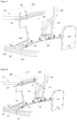
- the downstream end 33' of the external wall 33 is located longitudinally upstream of the front mounting flange 34. Due to this configuration, the support structure 52 has an inclination such that its orientation generally deviates forward from the longitudinal axis of the nacelle at the same time as it moves away from the longitudinal axis.
- FIGS. 3 And 5 also represent air inlets 3 according to embodiments illustrated here without the partition 50 to illustrate the offset of the downstream end 33' of the external wall 33 longitudinally upstream of the front mounting flange 34.
- equipment of the air inlet 3 such as a power supply for a defrosting system of the air inlet secured to the front partition 50' and an engine probe passing through the acoustic attenuation structure 60 equipping the internal wall 32.
- downstream end 33' of the external wall 33 may be located longitudinally substantially at the level of the front mounting flange 34 (see Figure 6A ), or be located longitudinally substantially downstream of the front mounting flange 34 (see the Figure 6B ).
- downstream of the front mounting flange means downstream of the upstream end of the flange, i.e. downstream of a joining plane between the two flanges in the assembled position.
- At least the internal wall 32 of the air intake 3 is equipped with an acoustic attenuation structure 60, which is located in the space delimited by the main wall, namely the internal wall 32, the external wall 33 and the front lip 31.
- This acoustic attenuation structure 60 is in the form of a panel with a honeycomb core forming a honeycomb structure whose cells delimit acoustic cells, the acoustic structure further comprising a solid internal skin ensuring in particular the mechanical strength of the panel.
- This acoustic structure 60 is preferably formed from composite materials. Where the temperatures involved allow, other materials may be used. These materials may also depend on the manufacturing process used, for example by thermoplastic molding, by additive manufacturing in aluminum, etc.
- the middle section also includes such an acoustic structure equipping in particular at least in part the casing 42 of the fan 5.
- the mounting flanges 34 and rear 44 are integral with these respective acoustic structures 60.
- FIG. 7 illustrates a detailed view of a support structure 50 according to one embodiment during a maintenance operation of the air inlet 3.
- the support of the air inlet 3 by the support structure 50 is discontinuous around the wall of the turbojet engine of the fan casing (as illustrated in particular on the Figure 4 )
- it is sufficient to detach the external wall 33 from the support structure 50 for example by first removing the fan cowls (if they are fixed) or opening them (if they are mobile and/or articulated), then said external wall 33 is detached from the support structure 50.
- the support structure 50 remains fixed to the fan casing during the removal of the air intake.
- Said support structure 50 is arranged to form, by its material configuration, access windows 70 configured to be sufficiently small to guarantee the structural integrity of the nacelle and sufficiently large to be passed through by maintenance tools 80 during maintenance operations on the air intake 3. It is then easy to access both the front mounting flange 34 and the rear flange 44.
- Such a support structure 50 supporting the external wall 33 of the air inlet 3 and configured discontinuously around the wall of the turbojet engine of the fan casing is generally dedicated to a non-fire environment, that is to say that there is no need for this type of nacelle to locally protect this geography of the nacelle from a risk of fire.
- the support structure 50 comprises a partition which, generally, is continuous around the wall of the turbojet engine of the fan casing.
- the support structure 50 comprises a partition
- said partition can be segmented, but is preferably solid, that is to say continuous, when it provides a fire-carrying function.
- Said support structure 50 being continuous, it is configured to have access windows 70 configured to be large enough to be passed through by maintenance tools 80 during maintenance operations of the air inlet 3.
- an access window 70 is delimited by edges of the partition 50 on the one hand and by the rear flange 44 on the other hand.
- a closing partition or hatch 54 is also provided to close the access windows 70 during use of the nacelle in order to guarantee the continuity of thermal protection, if this is necessary.
- the support structure 50 comprises a partition
- said partition may be segmented. It is preferably solid when it provides a fire-carrying function.
- Such a support structure 50 of the downstream edge 33' of the external wall 33 of the air inlet directly connected to the fan casing 42, and not to the internal wall 32 is particularly advantageous in terms of force absorption. This concept also allows easy access for maintainability needs to the flanges 34, 44 and the equipment present in the air inlet such as for example the defrosting tube.
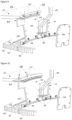
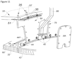
- THE figures 8 , 9 , 10 And 11 illustrate perspective views of a support structure 50 according to different attachment variants with the external wall 33 of the air inlet 3 and the external fan cowl 43.
- downstream end 33' of the outer wall 33 is configured to support the front end 43' of the outer fan cowl 43 and be fixed thereto, in the assembled position.
- This external wall 33 comes to bear against the support surface 51 of the support structure 50.
- This support is also completed by fixing means for fixing the support structure 50 to said external wall 33 of the air inlet 3.
- These fixing means 35 can be, for example, screw-nut assemblies.
- downstream end 33' of the external wall 33 has a step dimensioned according to the radial thickness of said external fan cowl 43 so that the two walls 33, 43 successively forming the external aerodynamic line of the nacelle are continuous and flush.
- the junction of the downstream end 33' of the external wall 33 with the support structure 50 is located under the support zone of the outer fan cowl 43 on the external wall 33 of the air inlet 3. This makes it possible not to impact the quality of the lines and the cosmetic appearance by visible fixings. As a result, the possible fixing means can be larger and fewer in number.
- the front end 43' of the outer fan cowl 43 is in direct contact and fixed together with the downstream end 33' of the outer wall 33.
- the respective ends 33', 43' of the external walls 33 and of the outer fan cowl 43 can be abutted and supported directly on the support surface 51 of the support structure 50 (see for example the figures 10 And 11 ).
- the fixing means 35 allow the fixing of the downstream end 33' of the external wall 33 with the support structure 50 and the front end 43' of the external fan cowl 43 can simply be supported (see Figure 10 ) or similarly secured with the support structure 50 ( Figure 11 ).
Landscapes
- Engineering & Computer Science (AREA)
- Chemical & Material Sciences (AREA)
- Combustion & Propulsion (AREA)
- Mechanical Engineering (AREA)
- General Engineering & Computer Science (AREA)
- Aviation & Aerospace Engineering (AREA)
- Structures Of Non-Positive Displacement Pumps (AREA)
Claims (8)
- Lufteinlass (3) für eine Gondel (1) eines Flugzeugmotors (6), wobei der Lufteinlass (3) eine vordere Lippe (31) umfasst, die eine im Wesentlichen zylindrische Innenwand (32) und eine im Wesentlichen zylindrische Außenwand (33) verbindet, einen vorderen Montageflansch (34) umfasst, der dafür konfiguriert ist, mit einem hinteren Flansch (44) einer Wand des Turbotriebwerks, die ein Gebläsegehäuse (42) bildet, zusammenzuwirken, wobei der Lufteinlasseine Trägerstruktur (50) aufweist, die sich von einem unteren Ende, das dafür konfiguriert ist, fest mit dem Gebläsegehäuse (42) verbunden zu werden, über den hinteren Flansch (44) bis zu einem oberen Ende erstreckt, das mindestens mit einem stromabwärtigen Teil der Außenwand (33) des Lufteinlasses (3) in Kontakt steht, wobei die Trägerstruktur (50) Zugangsfenster (70) umfasst oder bildet, die dafür konfiguriert sind,bei Wartungsarbeiten am Lufteinlass (3) von Wartungswerkzeugen durchquert zu werden, dadurch gekennzeichnet, dass das untere Ende der Trägerstruktur (50) dafür konfiguriert ist, fest mit einer hinteren Seite (441) des hinteren Flansches (44) verbunden zu werden.
- Lufteinlass (3) nach Anspruch 1, dadurch gekennzeichnet, dass die Lufteinlasslippe (31) in die Innen- (32) und/oder die Außenwand (33) integriert werden kann, um eine einteilige Wand zu bilden.
- Lufteinlass (3) nach Anspruch 1 oder 2, dadurch gekennzeichnet, dass die Trägerstruktur (50) durchgehend um die Wand des Turbotriebwerks, die das Gebläsegehäuse bildet, herum angeordnet ist, und zum Beispiel eine Trennwand umfasst, und/oder nicht durchgehend um die Wand des Turbotriebwerks des Gebläsegehäuses herum, und zum Beispiel einen Satz Trägerstangen (52) umfasst.
- Lufteinlass (3) nach einem der vorstehenden Ansprüche, dadurch gekennzeichnet, dass der vordere Montageflansch (34) und der hintere Flansch (44) durch Befestigungsmittel (45) aneinander befestigt sind, wobei die Trägerstruktur (50) mit allen oder einem Teil derselben Befestigungsmittel (45) am hinteren Flansch (44) befestigt ist.
- Lufteinlass (3) nach einem der vorstehenden Ansprüche, dadurch gekennzeichnet, dass der Teil der Außenwand (33), der dafür konfiguriert ist, mindestens mit dem oberen Ende der Trägerstruktur (50), vorzugsweise im Bereich einer Trägerfläche (51) der Trägerstruktur (50), in Kontakt zu kommen, ein stromabwärtiges Ende (33') der Außenwand (33) umfasst.
- Lufteinlass (3) nach einem der vorstehenden Ansprüche, dadurch gekennzeichnet, dass die Außenwand (33) zusätzlich dazu, dass sie an einer Trägerfläche (51) der Trägerstruktur (50) in Kontakt steht, an dieser anliegt und durch Befestigungsmitteln (35) an ihr befestigt ist.
- Lufteinlass (3) nach einem der vorstehenden Ansprüche, dadurch gekennzeichnet, dass das stromabwärtige Ende (33') der Außenwand (33) dafür konfiguriert ist, in zusammengebauter Position ein vorderes Ende (43') der äußeren Gebläsehaube (43) zu tragen, wobei dieser Träger vorzugsweise durch Befestigungsmitteln ergänzt ist.
- Gondel (1) für einen Flugzeugmotor, dadurch gekennzeichnet, dass sie einen Lufteinlass (3) nach einem der vorstehenden Ansprüche umfasst.
Applications Claiming Priority (2)
| Application Number | Priority Date | Filing Date | Title |
|---|---|---|---|
| FR1904429A FR3095418B1 (fr) | 2019-04-26 | 2019-04-26 | Entrée d’air de nacelle et nacelle comportant une telle entrée d’air |
| PCT/FR2020/050695 WO2020217026A1 (fr) | 2019-04-26 | 2020-04-23 | Entrée d'air de nacelle et nacelle comportant une telle entrée d'air |
Publications (2)
| Publication Number | Publication Date |
|---|---|
| EP3959136A1 EP3959136A1 (de) | 2022-03-02 |
| EP3959136B1 true EP3959136B1 (de) | 2025-06-11 |
Family
ID=67660295
Family Applications (1)
| Application Number | Title | Priority Date | Filing Date |
|---|---|---|---|
| EP20749928.6A Active EP3959136B1 (de) | 2019-04-26 | 2020-04-23 | Gondellufteinlass und gondel mit einem solchen lufteinlass |
Country Status (5)
| Country | Link |
|---|---|
| US (1) | US12103694B2 (de) |
| EP (1) | EP3959136B1 (de) |
| CN (1) | CN113727912A (de) |
| FR (1) | FR3095418B1 (de) |
| WO (1) | WO2020217026A1 (de) |
Families Citing this family (7)
| Publication number | Priority date | Publication date | Assignee | Title |
|---|---|---|---|---|
| CN115123556A (zh) * | 2022-08-15 | 2022-09-30 | 上海时的科技有限公司 | 一种适用于倾转旋翼飞行器短舱的引气结构 |
| FR3148006A1 (fr) * | 2023-04-21 | 2024-10-25 | Airbus Operations (S.A.S.) | Entrée d’air d’une nacelle d’aéronef comprenant des renforts radiaux arrières disjoints, ensemble de propulsion et aéronef comprenant ladite entrée d’air |
| EP4470920A1 (de) * | 2023-05-29 | 2024-12-04 | Airbus Operations (S.A.S.) | Flugzeugantriebsanordnung mit mindestens einem aerodynamischen panel, die von mindestens einem radialen zwischenträger getragen wird, luftfahrzeug, das mindestens eine solche antriebsanordnung umfasst |
| US12280884B2 (en) * | 2023-08-08 | 2025-04-22 | Rohr, Inc. | Outer barrel support structure for nacelle inlet structure |
| US12600487B2 (en) | 2023-08-08 | 2026-04-14 | Rohr, Inc. | Segmented nacelle inlet lip with electric anti-icing system |
| US12326113B2 (en) | 2023-08-08 | 2025-06-10 | Rohr, Inc. | Segmented nacelle inlet lip with electric anti-icing system |
| US12296971B2 (en) | 2023-08-08 | 2025-05-13 | Rohr, Inc. | Segmented nacelle inlet lip with electric anti-icing system |
Citations (5)
| Publication number | Priority date | Publication date | Assignee | Title |
|---|---|---|---|---|
| FR2856379A1 (fr) * | 2003-06-18 | 2004-12-24 | Airbus France | Moteur d'avion dont les capots de soufflante et d'inverseurs de poussee sont separes par un jeu reduit |
| US20080016844A1 (en) * | 2006-07-19 | 2008-01-24 | Shutrump Jeffrey D | Aircraft engine inlet having zone of deformation |
| FR2966126A1 (fr) * | 2010-10-15 | 2012-04-20 | Airbus Operations Sas | Nacelle d'aeronef incorporant un cadre arriere incline vers l'arriere |
| FR2998548A1 (fr) * | 2012-11-23 | 2014-05-30 | Airbus Operations Sas | Nacelle d'aeronef comprenant une liaison renforcee entre une entree d'air et une motorisation |
| FR3016159A1 (fr) * | 2014-01-03 | 2015-07-10 | Airbus Operations Sas | Nacelle de turboreacteur d'aeronef comprenant un ensemble d'entree d'air a rigidite augmentee |
Family Cites Families (6)
| Publication number | Priority date | Publication date | Assignee | Title |
|---|---|---|---|---|
| US5841079A (en) | 1997-11-03 | 1998-11-24 | Northrop Grumman Corporation | Combined acoustic and anti-ice engine inlet liner |
| US6688558B2 (en) | 1999-11-23 | 2004-02-10 | The Boeing Company | Method and apparatus for aircraft inlet ice protection |
| US7503425B2 (en) * | 2006-10-02 | 2009-03-17 | Spirit Aerosystems, Inc. | Integrated inlet attachment |
| FR2907098B1 (fr) * | 2006-10-11 | 2010-04-16 | Aircelle Sa | Nacelle pour turboreacteur double flux |
| FR3004700B1 (fr) * | 2013-04-19 | 2015-04-03 | Aircelle Sa | Nacelle pour turboreacteur d’aeronef a levre avant etendue |
| US11125157B2 (en) * | 2017-09-22 | 2021-09-21 | The Boeing Company | Advanced inlet design |
-
2019
- 2019-04-26 FR FR1904429A patent/FR3095418B1/fr active Active
-
2020
- 2020-04-23 WO PCT/FR2020/050695 patent/WO2020217026A1/fr not_active Ceased
- 2020-04-23 CN CN202080031530.6A patent/CN113727912A/zh active Pending
- 2020-04-23 EP EP20749928.6A patent/EP3959136B1/de active Active
-
2021
- 2021-10-26 US US17/510,626 patent/US12103694B2/en active Active
Patent Citations (5)
| Publication number | Priority date | Publication date | Assignee | Title |
|---|---|---|---|---|
| FR2856379A1 (fr) * | 2003-06-18 | 2004-12-24 | Airbus France | Moteur d'avion dont les capots de soufflante et d'inverseurs de poussee sont separes par un jeu reduit |
| US20080016844A1 (en) * | 2006-07-19 | 2008-01-24 | Shutrump Jeffrey D | Aircraft engine inlet having zone of deformation |
| FR2966126A1 (fr) * | 2010-10-15 | 2012-04-20 | Airbus Operations Sas | Nacelle d'aeronef incorporant un cadre arriere incline vers l'arriere |
| FR2998548A1 (fr) * | 2012-11-23 | 2014-05-30 | Airbus Operations Sas | Nacelle d'aeronef comprenant une liaison renforcee entre une entree d'air et une motorisation |
| FR3016159A1 (fr) * | 2014-01-03 | 2015-07-10 | Airbus Operations Sas | Nacelle de turboreacteur d'aeronef comprenant un ensemble d'entree d'air a rigidite augmentee |
Also Published As
| Publication number | Publication date |
|---|---|
| FR3095418A1 (fr) | 2020-10-30 |
| FR3095418B1 (fr) | 2021-09-24 |
| WO2020217026A1 (fr) | 2020-10-29 |
| US12103694B2 (en) | 2024-10-01 |
| CN113727912A (zh) | 2021-11-30 |
| US20220041295A1 (en) | 2022-02-10 |
| EP3959136A1 (de) | 2022-03-02 |
Similar Documents
| Publication | Publication Date | Title |
|---|---|---|
| EP3959136B1 (de) | Gondellufteinlass und gondel mit einem solchen lufteinlass | |
| EP2986507B1 (de) | Gondel für flugzeugturbostrahltriebwerk mit verlängerter frontlippe | |
| EP0898063B1 (de) | Geräuschdämpfungseinrichtung für ein Mantelstromtriebwerk | |
| EP2222560B1 (de) | Anlage für eine flugzeuggondelführungssystem | |
| EP2288797B1 (de) | Antriebseinheit für ein flugzeug und lufteintrittsstruktur für eine derartige einheit | |
| FR2977567A1 (fr) | Procede de refroidissement d'un plancher de protection thermique d'un carenage aerodynamique arriere d'un mat d'accrochage d'un ensemble propulsif d'aeronef | |
| FR3083777A1 (fr) | Entree d'air, nacelle et ensemble propulsif d'aeronef a secteurs monoblocs | |
| FR3095416A1 (fr) | Entrée d’air de nacelle de turboréacteur | |
| FR2891526A1 (fr) | Mat d'accrochage de turboreacteur pour aeronef | |
| EP3959138B1 (de) | Gondellufteinlass und gondel mit einem solchen lufteinlass | |
| EP3959137B1 (de) | Lufteinlass einer gondel und gondel mit einem solchen lufteinlass | |
| EP3792469B1 (de) | Lufteinlass, gondel, antriebseinheit und luftfahrzeug mit gerillter einlasslippe | |
| FR3120352A1 (fr) | Entree d’air de nacelle munie d’un système de protection contre la glace mixte | |
| EP2344382B1 (de) | Gondellufteinlassstruktur | |
| EP3976953B1 (de) | Flugzeugantriebsanordnung | |
| EP3983655B1 (de) | Turbinenfangehäuse | |
| FR2995026B1 (fr) | Cadre avant pour une structure d'inverseur de poussee a grilles de deviation | |
| EP3959134B1 (de) | Lufteinlass einer gondel mit akustikplatte | |
| FR3059301A1 (fr) | Systeme d'echappement d'un moteur auxiliaire de puissance | |
| FR3086643A1 (fr) | Nacelle pour aeronef et entree d'air associee | |
| FR3040044A1 (fr) | Capot de nacelle comportant un element de maintien en position solidarise a la paroi interne du capot | |
| FR3028290A1 (fr) | Ecope de prise d’air pour nacelle d’aeronef |
Legal Events
| Date | Code | Title | Description |
|---|---|---|---|
| STAA | Information on the status of an ep patent application or granted ep patent |
Free format text: STATUS: UNKNOWN |
|
| STAA | Information on the status of an ep patent application or granted ep patent |
Free format text: STATUS: THE INTERNATIONAL PUBLICATION HAS BEEN MADE |
|
| PUAI | Public reference made under article 153(3) epc to a published international application that has entered the european phase |
Free format text: ORIGINAL CODE: 0009012 |
|
| STAA | Information on the status of an ep patent application or granted ep patent |
Free format text: STATUS: REQUEST FOR EXAMINATION WAS MADE |
|
| 17P | Request for examination filed |
Effective date: 20211112 |
|
| AK | Designated contracting states |
Kind code of ref document: A1 Designated state(s): AL AT BE BG CH CY CZ DE DK EE ES FI FR GB GR HR HU IE IS IT LI LT LU LV MC MK MT NL NO PL PT RO RS SE SI SK SM TR |
|
| DAV | Request for validation of the european patent (deleted) | ||
| DAX | Request for extension of the european patent (deleted) | ||
| STAA | Information on the status of an ep patent application or granted ep patent |
Free format text: STATUS: EXAMINATION IS IN PROGRESS |
|
| 17Q | First examination report despatched |
Effective date: 20230626 |
|
| GRAP | Despatch of communication of intention to grant a patent |
Free format text: ORIGINAL CODE: EPIDOSNIGR1 |
|
| STAA | Information on the status of an ep patent application or granted ep patent |
Free format text: STATUS: GRANT OF PATENT IS INTENDED |
|
| INTG | Intention to grant announced |
Effective date: 20250115 |
|
| GRAS | Grant fee paid |
Free format text: ORIGINAL CODE: EPIDOSNIGR3 |
|
| GRAA | (expected) grant |
Free format text: ORIGINAL CODE: 0009210 |
|
| STAA | Information on the status of an ep patent application or granted ep patent |
Free format text: STATUS: THE PATENT HAS BEEN GRANTED |
|
| AK | Designated contracting states |
Kind code of ref document: B1 Designated state(s): AL AT BE BG CH CY CZ DE DK EE ES FI FR GB GR HR HU IE IS IT LI LT LU LV MC MK MT NL NO PL PT RO RS SE SI SK SM TR |
|
| REG | Reference to a national code |
Ref country code: GB Ref legal event code: FG4D Free format text: NOT ENGLISH |
|
| REG | Reference to a national code |
Ref country code: CH Ref legal event code: EP |
|
| REG | Reference to a national code |
Ref country code: DE Ref legal event code: R096 Ref document number: 602020052614 Country of ref document: DE |
|
| REG | Reference to a national code |
Ref country code: IE Ref legal event code: FG4D Free format text: LANGUAGE OF EP DOCUMENT: FRENCH |
|
| PG25 | Lapsed in a contracting state [announced via postgrant information from national office to epo] |
Ref country code: ES Free format text: LAPSE BECAUSE OF FAILURE TO SUBMIT A TRANSLATION OF THE DESCRIPTION OR TO PAY THE FEE WITHIN THE PRESCRIBED TIME-LIMIT Effective date: 20250611 Ref country code: FI Free format text: LAPSE BECAUSE OF FAILURE TO SUBMIT A TRANSLATION OF THE DESCRIPTION OR TO PAY THE FEE WITHIN THE PRESCRIBED TIME-LIMIT Effective date: 20250611 |
|
| REG | Reference to a national code |
Ref country code: LT Ref legal event code: MG9D |
|
| PG25 | Lapsed in a contracting state [announced via postgrant information from national office to epo] |
Ref country code: NO Free format text: LAPSE BECAUSE OF FAILURE TO SUBMIT A TRANSLATION OF THE DESCRIPTION OR TO PAY THE FEE WITHIN THE PRESCRIBED TIME-LIMIT Effective date: 20250911 Ref country code: GR Free format text: LAPSE BECAUSE OF FAILURE TO SUBMIT A TRANSLATION OF THE DESCRIPTION OR TO PAY THE FEE WITHIN THE PRESCRIBED TIME-LIMIT Effective date: 20250912 |
|
| REG | Reference to a national code |
Ref country code: NL Ref legal event code: MP Effective date: 20250611 |
|
| PG25 | Lapsed in a contracting state [announced via postgrant information from national office to epo] |
Ref country code: BG Free format text: LAPSE BECAUSE OF FAILURE TO SUBMIT A TRANSLATION OF THE DESCRIPTION OR TO PAY THE FEE WITHIN THE PRESCRIBED TIME-LIMIT Effective date: 20250611 |
|
| PG25 | Lapsed in a contracting state [announced via postgrant information from national office to epo] |
Ref country code: HR Free format text: LAPSE BECAUSE OF FAILURE TO SUBMIT A TRANSLATION OF THE DESCRIPTION OR TO PAY THE FEE WITHIN THE PRESCRIBED TIME-LIMIT Effective date: 20250611 |
|
| PG25 | Lapsed in a contracting state [announced via postgrant information from national office to epo] |
Ref country code: RS Free format text: LAPSE BECAUSE OF FAILURE TO SUBMIT A TRANSLATION OF THE DESCRIPTION OR TO PAY THE FEE WITHIN THE PRESCRIBED TIME-LIMIT Effective date: 20250911 |
|
| PG25 | Lapsed in a contracting state [announced via postgrant information from national office to epo] |
Ref country code: LV Free format text: LAPSE BECAUSE OF FAILURE TO SUBMIT A TRANSLATION OF THE DESCRIPTION OR TO PAY THE FEE WITHIN THE PRESCRIBED TIME-LIMIT Effective date: 20250611 |
|
| PG25 | Lapsed in a contracting state [announced via postgrant information from national office to epo] |
Ref country code: NL Free format text: LAPSE BECAUSE OF FAILURE TO SUBMIT A TRANSLATION OF THE DESCRIPTION OR TO PAY THE FEE WITHIN THE PRESCRIBED TIME-LIMIT Effective date: 20250611 |
|
| PG25 | Lapsed in a contracting state [announced via postgrant information from national office to epo] |
Ref country code: PT Free format text: LAPSE BECAUSE OF FAILURE TO SUBMIT A TRANSLATION OF THE DESCRIPTION OR TO PAY THE FEE WITHIN THE PRESCRIBED TIME-LIMIT Effective date: 20251013 |
|
| REG | Reference to a national code |
Ref country code: AT Ref legal event code: MK05 Ref document number: 1802175 Country of ref document: AT Kind code of ref document: T Effective date: 20250611 |
|
| PG25 | Lapsed in a contracting state [announced via postgrant information from national office to epo] |
Ref country code: IS Free format text: LAPSE BECAUSE OF FAILURE TO SUBMIT A TRANSLATION OF THE DESCRIPTION OR TO PAY THE FEE WITHIN THE PRESCRIBED TIME-LIMIT Effective date: 20251011 |
|
| PG25 | Lapsed in a contracting state [announced via postgrant information from national office to epo] |
Ref country code: AT Free format text: LAPSE BECAUSE OF FAILURE TO SUBMIT A TRANSLATION OF THE DESCRIPTION OR TO PAY THE FEE WITHIN THE PRESCRIBED TIME-LIMIT Effective date: 20250611 Ref country code: SM Free format text: LAPSE BECAUSE OF FAILURE TO SUBMIT A TRANSLATION OF THE DESCRIPTION OR TO PAY THE FEE WITHIN THE PRESCRIBED TIME-LIMIT Effective date: 20250611 |
|
| PG25 | Lapsed in a contracting state [announced via postgrant information from national office to epo] |
Ref country code: CZ Free format text: LAPSE BECAUSE OF FAILURE TO SUBMIT A TRANSLATION OF THE DESCRIPTION OR TO PAY THE FEE WITHIN THE PRESCRIBED TIME-LIMIT Effective date: 20250611 |
|
| PG25 | Lapsed in a contracting state [announced via postgrant information from national office to epo] |
Ref country code: PL Free format text: LAPSE BECAUSE OF FAILURE TO SUBMIT A TRANSLATION OF THE DESCRIPTION OR TO PAY THE FEE WITHIN THE PRESCRIBED TIME-LIMIT Effective date: 20250611 |
|
| PG25 | Lapsed in a contracting state [announced via postgrant information from national office to epo] |
Ref country code: EE Free format text: LAPSE BECAUSE OF FAILURE TO SUBMIT A TRANSLATION OF THE DESCRIPTION OR TO PAY THE FEE WITHIN THE PRESCRIBED TIME-LIMIT Effective date: 20250611 |
|
| PG25 | Lapsed in a contracting state [announced via postgrant information from national office to epo] |
Ref country code: SK Free format text: LAPSE BECAUSE OF FAILURE TO SUBMIT A TRANSLATION OF THE DESCRIPTION OR TO PAY THE FEE WITHIN THE PRESCRIBED TIME-LIMIT Effective date: 20250611 Ref country code: RO Free format text: LAPSE BECAUSE OF FAILURE TO SUBMIT A TRANSLATION OF THE DESCRIPTION OR TO PAY THE FEE WITHIN THE PRESCRIBED TIME-LIMIT Effective date: 20250611 |
|
| PGFP | Annual fee paid to national office [announced via postgrant information from national office to epo] |
Ref country code: GB Payment date: 20260327 Year of fee payment: 7 |
|
| PG25 | Lapsed in a contracting state [announced via postgrant information from national office to epo] |
Ref country code: DK Free format text: LAPSE BECAUSE OF FAILURE TO SUBMIT A TRANSLATION OF THE DESCRIPTION OR TO PAY THE FEE WITHIN THE PRESCRIBED TIME-LIMIT Effective date: 20250611 |
|
| PG25 | Lapsed in a contracting state [announced via postgrant information from national office to epo] |
Ref country code: IT Free format text: LAPSE BECAUSE OF FAILURE TO SUBMIT A TRANSLATION OF THE DESCRIPTION OR TO PAY THE FEE WITHIN THE PRESCRIBED TIME-LIMIT Effective date: 20250611 |
|
| PLBE | No opposition filed within time limit |
Free format text: ORIGINAL CODE: 0009261 |
|
| STAA | Information on the status of an ep patent application or granted ep patent |
Free format text: STATUS: NO OPPOSITION FILED WITHIN TIME LIMIT |
|
| REG | Reference to a national code |
Ref country code: CH Ref legal event code: L10 Free format text: ST27 STATUS EVENT CODE: U-0-0-L10-L00 (AS PROVIDED BY THE NATIONAL OFFICE) Effective date: 20260423 |