EP3959131B1 - Hoist system and process for sway control - Google Patents
Hoist system and process for sway control Download PDFInfo
- Publication number
- EP3959131B1 EP3959131B1 EP20794786.2A EP20794786A EP3959131B1 EP 3959131 B1 EP3959131 B1 EP 3959131B1 EP 20794786 A EP20794786 A EP 20794786A EP 3959131 B1 EP3959131 B1 EP 3959131B1
- Authority
- EP
- European Patent Office
- Prior art keywords
- load
- sensor
- cable
- motor
- measurement
- Prior art date
- Legal status (The legal status is an assumption and is not a legal conclusion. Google has not performed a legal analysis and makes no representation as to the accuracy of the status listed.)
- Active
Links
Images



Classifications
-
- B—PERFORMING OPERATIONS; TRANSPORTING
- B64—AIRCRAFT; AVIATION; COSMONAUTICS
- B64D—EQUIPMENT FOR FITTING IN OR TO AIRCRAFT; FLIGHT SUITS; PARACHUTES; ARRANGEMENT OR MOUNTING OF POWER PLANTS OR PROPULSION TRANSMISSIONS IN AIRCRAFT
- B64D1/00—Dropping, ejecting, releasing or receiving articles, liquids, or the like, in flight
- B64D1/22—Taking-up articles from earth's surface
-
- B—PERFORMING OPERATIONS; TRANSPORTING
- B64—AIRCRAFT; AVIATION; COSMONAUTICS
- B64C—AEROPLANES; HELICOPTERS
- B64C27/00—Rotorcraft; Rotors peculiar thereto
- B64C27/04—Helicopters
-
- B—PERFORMING OPERATIONS; TRANSPORTING
- B66—HOISTING; LIFTING; HAULING
- B66C—CRANES; LOAD-ENGAGING ELEMENTS OR DEVICES FOR CRANES, CAPSTANS, WINCHES, OR TACKLES
- B66C1/00—Load-engaging elements or devices attached to lifting or lowering gear of cranes or adapted for connection therewith for transmitting lifting forces to articles or groups of articles
- B66C1/10—Load-engaging elements or devices attached to lifting or lowering gear of cranes or adapted for connection therewith for transmitting lifting forces to articles or groups of articles by mechanical means
- B66C1/22—Rigid members, e.g. L-shaped members, with parts engaging the under surface of the loads; Crane hooks
- B66C1/34—Crane hooks
- B66C1/40—Crane hooks formed or fitted with load measuring or indicating devices
-
- B—PERFORMING OPERATIONS; TRANSPORTING
- B66—HOISTING; LIFTING; HAULING
- B66D—CAPSTANS; WINCHES; TACKLES, e.g. PULLEY BLOCKS; HOISTS
- B66D1/00—Rope, cable, or chain winding mechanisms; Capstans
- B66D1/28—Other constructional details
- B66D1/40—Control devices
- B66D1/48—Control devices automatic
- B66D1/485—Control devices automatic electrical
Definitions
- Helicopter hoist equipment typically includes a lifting device such as a hoist, which is attached to the helicopter, a hoist cable, and a hook located at a distal end of the hoist cable for direct or indirect attachment to a person, animal, and/or object (load) for rescue, transport, lift, and/or the like.
- the helicopter hoist equipment usually has a rotary drum for winding in and out the hoist cable that serves to lift or transport the load.
- a crew member in the helicopter typically controls the helicopter hoist equipment including raising and lowering of the hook.
- the environment in which the helicopter or other aircraft operates as well as the lifting device and the load that is being lifted is highly dynamic and includes or is subjected to various forces, accelerations, movements, and/or the like.
- a common issue with this environment is that the load may sway or oscillate back and forth, side to side, or combination thereof below the helicopter presenting a risk to safe operation of the helicopter as well as presenting a safety issue for the load.
- US2016/009393 describes a helicopter-hoist system.
- the system may include: hoist equipment, illumination systems, range-measuring equipment, camera(s), communication systems, display devices, processing/control systems including image-processing systems, and power-management systems.
- the system may also include a smart-hook for measuring a load on the hook. Based on the measured load on the cable, the lighting may be illuminated in different manners.
- the system may communicate with display devices, which render images of a mission to helicopter crew members or other observers.
- Measured parameters appurtenant to the mission such as the weight of the load, height of the smart-hook above a surface, altitude of the aircraft, distance between the aircraft and end of the hook, location of the hook in three-dimensional space, forces on the hook and cable, and other mission-critical information-may be overlaid, or rendered proximate to the real images to provide crew members with a full understanding of a mission.
- EP3428114 discloses a self-homing hoist including a controller configured to initiate a self-homing process to return the hook assembly to a homed position in response to each of at least one homing factor being true.
- Each homing factor is true or false based on a comparison of the current condition, determined by a plurality of sensors, of the homing factor with a threshold requirement. If the current condition satisfies the threshold requirement, then the homing factor is true. If the current condition does not satisfy the threshold requirement, then the homing factor is false. Where all homing factors are true, the controller can initiate the self-homing process by activating a hoist motor to drive the cable drum and reel the hook assembly into the homed position.
- US2018/237276 presents an unmanned aerial vehicle (UAV) including a winch system, wherein the winch system includes a single winch line, wherein a payload is suspended from a first end of the winch line, and the winch system is controllable to vary the rate of ascent of the payload to the UAV, and a control system including a processor and program instructions stored in a non-transitory computer readable medium and executable by the processor to control the winch, the control system configured to (a) receive data regarding oscillations of the payload, and (b) operate the winch system to vary a retraction rate of the winch line to damp oscillations of the payload during ascent of the payload to the UAV.
- UAV unmanned aerial vehicle
- a system and process to control the sway of the load and an associated portion of the lifting device is needed to ensure safe operation of the aircraft and a safety of the load.
- an aircraft hoist system as set out in the appended independent claim 1.
- a method of controlling an aircraft hoist system as set out in the appended independent claim 2.
- Figure 1 shows a helicopter with an exemplary helicopter hoist system in accordance with aspects of the disclosure.
- Figure 1 shows a helicopter 100 with a hoist system 101, which may be used for search and rescue missions, transport missions, combat insertion missions, combat extraction missions, and/or the like.
- the hoist system 101 may be implemented as a Helicopter Flight Rescue System (HFRS), a Helicopter External Transport System (HETS), and/or the like.
- HFRS Helicopter Flight Rescue System
- HETS Helicopter External Transport System
- the hoist system 101 may be positioned on an upper side of the aircraft, and may be attached directly or indirectly to the helicopter 100.
- the hoist system 101 may be mounted to a bottom of the helicopter 100, may be mounted to a side of the helicopter 100, may be mounted internally to the helicopter 100, and/or the like.
- Figure 1 depicts a helicopter as the exemplary aircraft
- the hoist system 101 and its associated principles/methodologies described herein are not limited to helicopters, and may be applied to any airborne platform.
- the hoist system 101 may be attached directly or indirectly to a cargo helicopter (not shown), such as mounted underneath an aircraft fuselage, mounted to a tilt rotor aircraft, aerial crane, flying crane and/or the like.
- the hoist system 101 may also be coupled to an autonomous or remote controlled aircraft, such as an unmanned aerial vehicle, unmanned aircraft system (UAV/UAS), a drone, fixed wing aircraft, and the like.
- UAV/UAS unmanned aerial vehicle
- UAV/UAS unmanned aircraft system
- the hoist system 101 may also be implemented in static configurations, non-aircraft based configurations, and/or the like.
- the hoist system 101 includes a hook 102 and a cable 104.
- the hook 102 may be positioned between the cable 104 and a hook portion 106. That is, the hook 102 may be connected to the cable 104 at its upper end, and may be connected to the hook portion 106 (or another object) on its lower end.
- the hook 102 may be connected directly or indirectly to the cable 104 and the hook portion 106.
- a spring-interface device 108 may be connected between the cable 104 and the hook 102.
- the cable 104 may be connected directly to the hook portion 106.
- the cable 104 may be connected to the hook portion 106 through the spring-interface device 108.
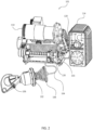
- Figure 2 illustrates an enlarged view of components of the helicopter hoist system shown in Figure 1 .
- Figure 2 illustrates an enlarged view of the hoist system 101 shown in Figure 1 , with the cable 104 in a generally retracted position.
- the hoist system 101 may include a frame 103 on which the hoist equipment (i.e., the cable 104, the hook 102, the hook portion 106, and/or a motor 110).
- the hoist system 101 may include an electronic system 114 that may include a housing.
- the electronic system 114 may include lighting, lighting systems, lasers, laser systems, cameras, camera systems, communication systems, communication equipment, electronics and processing equipment, and/or the like.
- the hoist system 101 includes a motor 110.
- the motor 110 may be a brushless motor, which may provide smoother raising and lowering of the cable 104.
- the motor 110 may include a high-performance variable-speed brushless permanent magnet rotary servomotor, with Universal AC or DC power input.
- the torque output may range between 5.6 Nm and 13.9 Nm. As appreciated by those skilled in the art, the torque range may vary and may be less than or more than 5.6 Nm and 13.9 Nm.
- any suitable motor or motors may be implemented as part of the hoist equipment.
- the hoist system 101 may include a transmission, a rotary drum, and/or the like.
- the electronic system 114 also may include a host of other electronic equipment, which are not shown in Figure 2 , but are described in more detail below including communication systems, antenna, processing/control systems including image-processing systems, power-management systems, control systems, motor control systems, sensor systems, and/or the like.
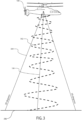
- Figure 3 illustrates a path of a load being lifted to a helicopter without sway control.
- Figure 3 illustrates the helicopter 100 lifting a load (not shown) that is attached to the cable 104.
- Figure 3 illustrates the path 302 the load makes as it is lifted to the helicopter 100 without sway control.
- the path 302 illustrates substantial sway and/or oscillation and the path 302 approaches and at times exceeds a 30° angle shown by line 304 as illustrated in Figure 3 as the load is lifted from the ground 360 to the helicopter 100.
- the operation illustrated in Figure 3 presents a risk to safe operation of the helicopter 100 as well as presenting a safety issue for the load.
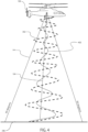
- Figure 4 illustrates a path of a load being lifted to a helicopter without sway control superimposed on a load being lifted to a helicopter with sway control in accordance with aspects of the disclosure.
- Figure 4 illustrates the helicopter 100 lifting a load (not shown) on the cable 104.
- Figure 4 illustrates the path 302 the load makes as it is lifted to the helicopter 100 without sway control as described above.
- Figure 4 further illustrates a path 402 the load makes as it is lifted to the helicopter 100 with sway control implemented as described below.
- the operation illustrated in Figure 4 utilizing sway control decreases a risk to safe operation of the helicopter 100 as well as increases a safety for the load.
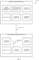
- Figure 5 illustrates a block diagram illustrating select components of an example helicopter hoist system in accordance with aspects of the disclosure.
- the load cell 306 may be implemented as a transducer that is used to create an electrical signal whose magnitude is directly proportional to or a function of the force being measured.
- the load cell 306 may be implemented as a hydraulic, a pneumatic, and/or a strain gauge load cell.
- the load cell 306 measures a force provided by the load. That is, the load cell 306 is positioned in a load path associated with the hook 102, the hook portion 106, and/or cable 104.
- the load cell 306 can have any construction and be positioned in hook 102, the hook portion 106, along cable 104 ( Figure 1 ) path, the motor 110, the frame 103, or the like in any suitable manner to acquire load data.
- the load cell 306 may measure at least in part roll, pitch, and/or yaw associated with the aircraft and/or the hook 102, the hook portion 106, and/or cable 104.
- the hoist system 101 may include one or more sensors to measure a length or distance of the cable 104, the hook portion 106, and/or the hook 102 from the helicopter 100.
- the hoist system 101 may include a distance sensor 320 associated with the motor 110, the frame 103, the cable 104, the hook portion 106, the hook 102, and/or the like.
- the hoist system 101 may associate the distance sensor 320 with the motor 110 and measure rotations of the motor 110 to determine a length of the cable 104 or the like.
- the hoist system 101 may associate the distance sensor 320 with the motor 110 and determine a length of the cable 104 payout or the like.
- the distance sensor 320 may be integrated in the hook 102 and/or the hook portion 106 and may be implemented as an inertial measurement unit (IMU). In one aspect, the distance sensor 320 may be integrated in the hook 102 and/or the hook portion 106 and may be implemented as a location determination device implemented as global navigation satellite system (GNSS) receiver.
- the hoist system 101 may also include range-measuring equipment 120 (such as a laser-range finder) for determining the distance of the hook 102 from the helicopter 100, and as well as the distance of objects or ground/water from helicopter 100.
- the hoist system 101 may also include a cable-payout and direction detector 122, which measures the distance the cable 104 is extended and a direction the cable 104 is moving (i.e., up or down).
- the hoist system 101 may determine an airspeed measurement of the helicopter 100. In one aspect, the hoist system 101 may receive an airspeed measurement from the helicopter 100. In one aspect, the airspeed measurement may be determined from a pitot-static system.
- the pitot-static system may include a system of pressure-sensitive instruments that determine an aircraft airspeed, Mach number, altitude, and/or altitude trend.
- the hoist system 101 may measure other flight dynamics and/or receive other flight dynamics data from the helicopter 100 or another associated system.
- the other flight dynamics data may include roll, roll rate, pitch, pitch rate, yaw, yaw rate, and/or the like data.
- the processor(s) 604 may be distributed in more than one computer system and over a network utilizing a transceiver operating on a communication channel as defined herein (not shown).
- Examples of the computer systems may include, but are not limited to, a server, personal computer, distributed computer systems, or other computing devices having access to processors and computer-readable medial.
- any number of system busses, communication and peripheral interfaces, input/output devices, and other devices may be included in the control system 609 (including the control system 310), as appreciated by those skilled in the art.
- the computer-readable media 606 may include any suitable computer-storage media including volatile and non-volatile memory, and any combination thereof.
- computer storage media includes volatile and non-volatile, removable and non-removable media implemented in any method or technology for storage of information such as computer readable instructions, data structures, program modules, or other data.
- Computer storage media may further include, but is not limited to, RAM, ROM, EEPROM, flash memory or other memory technology, CD-ROM, digital versatile disks (DVD) or other optical storage, magnetic cassettes, magnetic tape, magnetic disk storage or other magnetic storage devices, or any other non-transitory or non-transmission medium that can be used to store information for access by a computing device.
- the computer-readable media 606 stores a sway control process (Box 700) as described below.
- the computer-readable media 606 may be local and/or offsite to computer systems (not shown). For instance, one or more portions of, or all of data or code stored in the computer-readable media 606, may be accessed from a computer-storage medium local to and/or remote to the control system 609, such as from a storage medium connected to a network.
- Resident in the computer-readable media 606 may be one or more operating systems (not shown), and any number of other program applications or modules in the form of computer-executable instructions and/or logic which are executed on the processor(s) 604 to enable processing of data or other functionality.
- the control system 609 may be configured with a sensor-system-control module 608 that may be maintained in the computer-readable media 606.
- the sensor-system-control module 608 may be implemented as code in the form of computer-readable instructions that execute on the processor(s) 604.
- programs and other executable-program modules are illustrated herein as discrete blocks, although it is recognized that such programs and components may reside at various times in different storage components.
- code may be implemented as one or more applications or modules, or may be integrated as components within a single application.
- Such code stored in the computer-readable media 606 may be implemented across one or more computers in a cloud computing environment, on a local device or system, or on a combination of both. The following discussion does not limit the implementation of code stored in the computer-readable media 606 to any particular device or environment.
- the sensor-system-control module 608 may include components contained in the computer-readable media 606.
- the sensor-system-control module 608 includes: a lighting module 610, a position/load module 612, and a display module 614.
- the position/load module 612 facilitates a mode of operation of the control system 609 in which the position/load module 612 monitors measurements made by the load measurement sensors such as the load cell 306, the cable movement measurement sensors such as the distance sensor 320, the cable-payout and direction detector 122 and/or the range-measuring equipment 120, the aircraft movement measurement sensors such as the movement sensor 322, airspeed measurement sensors, other flight dynamics sensors, and/or the like.
- the load measurement sensors such as the load cell 306
- the cable movement measurement sensors such as the distance sensor 320, the cable-payout and direction detector 122 and/or the range-measuring equipment 120
- the aircraft movement measurement sensors such as the movement sensor 322, airspeed measurement sensors, other flight dynamics sensors, and/or the like.
- the position/load module 612 facilitates a mode of operation of the control system 609 in which the position/load module 612 monitors measurements made by an inertial measurement unit (IMU) and/or global positioning unit (GPS) (collectively referred to herein as IMS/GPS 602) located in the hook 102 and/or the electronic system 114.
- IMU inertial measurement unit
- GPS global positioning unit
- the position/load module 612 may also record these measurements (i.e., data) generated by the IMS/GPS 602, and transmit these measurements to the hoist system 101 as well as other monitoring devices, such as located in the helicopter 100.
- the IMS/GPS 602 may be in communication with the position/load module 612 and enable the control system 609 to monitor a location and/or relative motion of the hook 102 and/or the hook portion 106 in three-dimensional coordinate space relative to the helicopter.
- the IMS/GPS 602 under control of the control system 609 (including the control system 310 individually or in combination with the system 609 as a whole) may allow for mapping of the position, velocity, sway, oscillation, acceleration, and/or the like of the hook 102, the hook portion 106, and/or the load relative to the ground and/or aircraft.
- the IMS/GPS 602 under control of the control system 609 (including the control system 310 individually or in combination with the system 609 as a whole) may use the real-time load and acceleration data from the hook 102 to adjust the payout of the cable 104 (via hoist equipment such as the cable 104, the hook 102, and the motor 110) to actively dampen vibrations imparted to the hoist equipment and aircraft, actively reduce sway to the hoist equipment and aircraft, actively reduce oscillation to the hoist equipment and aircraft, and/or the like.
- hoist equipment such as the cable 104, the hook 102, and the motor 110
- this data allows for monitoring health and maintenance of the hoist system, and the number of hoist system cycles, and the ability to predict component wear and plan maintenance.
- this data allows for complete dynamic load mapping for the structural design of helicopter hoist mounts/interfaces.
- Real-time dynamic load information supplied by the control system 609 also allows for active hoist mounts that optimize the load transfer and energy management between the hook and the helicopter, providing for reduced shock loads on hoist components, helicopter mounts, and any personnel or cargo on the hook.
- Optimizing the dynamic response of the helicopter and hoist as a system can provide inputs to helicopter-flight controls for an optimized response during load transfer and flight.
- the dynamic response of the system may change based on cable length (i.e., pendulum effect on the cable), and the ability to optimize the helicopter system-level response with these sensor inputs may provide for improved flight control and stability during operations and cargo transfers.
- Figure 7 illustrates an exemplary sway control process on a load being lifted to a helicopter in accordance with aspects of the disclosure.
- Figure 7 illustrates a sway control process (Box 700) as a collection of blocks in a logical flow graph, which represent a sequence of operations that can be implemented in hardware, software, or a combination thereof.
- the blocks may represent computer-executable instructions that, when executed by one or more processors, perform the recited operations.
- computer-executable instructions may include routines, programs, objects, components, data structures, and/or the like that perform particular functions or implement particular abstract data types.
- the order in which the operations are described is not intended to be construed as a limitation, and any number of the described blocks can be combined in any order and/or in parallel to implement the process. Also, one or more of the described blocks may be omitted without departing from the scope of the present disclosure.
- the sway control process (Box 700) is merely exemplary and may be modified consistent with the various aspects disclosed herein.
- Figure 7 illustrates the sway control process (Box 700).
- the sway control process (Box 700) reduces sway of the cable 104 and the load.
- the sway control process (Box 700) reduces oscillation of the cable 104 and the load.
- the sway control process (Box 700) reduces sway and oscillation of the cable 104 and the load.
- the sway control process (Box 700) may be stored in the computer-readable media 606. In one aspect, the sway control process (Box 700) may be executed by the control system 609. In one aspect, the sway control process (Box 700) may be executed by the processor(s) 604.
- the sway control process (Box 700) of the disclosure may include determining whether sway control is enabled (box 702). Moreover, one or more proceeding or subsequent processes may also be implemented with determining whether sway control is enabled (box 702) consistent with the disclosure.
- the sway control process (Box 700) may be enabled or disabled by the pilot.
- the pilot may include an input device such as a switch or the like to manually enable the sway control process (Box 700) and/or disable the sway control process (Box 700).
- the sway control process (Box 700) may be configured to be selectively turned off for mission types which require immediate extraction.
- the sway control process (Box 700) may be configured to be automatically turned off for mission types which require immediate extraction.
- the sway control process (Box 700) may be configured to be automatically turned on for mission types which require increased safety. In one aspect, the sway control process (Box 700) may be configured to be automatically turned on or turned off based on information obtained through artificial intelligence.
- the artificial intelligence as described herein may utilize any number of approaches including one or more of cybernetics and brain simulation, symbolic, cognitive simulation, logic-based, anti-logic, knowledge-based, sub-symbolic, embodied intelligence, computational intelligence and soft computing, machine learning and statistics, neural networks, and/or the like.
- the artificial intelligence may be implemented by the control system 609, the processor(s) 604, or the like.
- the artificial intelligence may include inputs from one or more of the load measurement sensors such as the load cell 306, the cable movement measurement sensors such as the distance sensor 320, the cable-payout and direction detector 122 and/or the range-measuring equipment 120, the aircraft movement measurement sensors such as the movement sensor 322, airspeed measurement sensors, other flight dynamics sensors, and/or the like.
- the load measurement sensors such as the load cell 306, the cable movement measurement sensors such as the distance sensor 320, the cable-payout and direction detector 122 and/or the range-measuring equipment 120, the aircraft movement measurement sensors such as the movement sensor 322, airspeed measurement sensors, other flight dynamics sensors, and/or the like.
- the sway control process (Box 700) may obtain aircraft and load measurements (Box 704).
- the sway control process (Box 700) may obtain aircraft and load measurements (Box 704) that include one or more of the outputs from the load measurement sensors such as the load cell 306, the cable movement measurement sensors such as the distance sensor 320, the cable-payout and direction detector 122 and/or the range-measuring equipment 120, the aircraft movement measurement sensors such as the movement sensor 322, the airspeed measurement sensors, other flight dynamics sensors, and/or the like.
- the sway control process (Box 700) of the disclosure may include the hoist system 101 or other components operating to receive human control input (Box 705).
- the human input may be from movements of controls of an electronic interface from the pilot and/or crew.
- the movements of the controls may be converted to electronic signals by the hoist system 101.
- the human input may include an indication with respect to a lift direction, a lift velocity, and/or the like.
- the hoist system 101 and the sway control process (Box 700) may be configured to modify existing human commands for hoist actuation and hoist movement in terms of scale input, and not directly actuate a hoist motor or movement otherwise.
- the hoist system 101 may be configured to replace the manual controls with an electronic interface.
- the movements of controls of the electronic interface may be converted to electronic signals and the hoist system 101 and/or the sway control process (Box 700) may determine how to operate the hoist system 101 to provide an ordered response to movements of the controls.
- the sway control process (Box 700) may determine appropriate controls for the motor (Box 706). In one aspect, the sway control process (Box 700) may determine appropriate controls for the motor (Box 706) based at least in part on the output from the sensors and the human input. In one aspect, the sway control process (Box 700) may determine appropriate speed for the motor 110 currently lifting the load. In one aspect, the sway control process (Box 700) may determine appropriate deceleration for the motor 110 currently lifting the load. In one aspect, the sway control process (Box 700) may determine appropriate acceleration for the motor 110 currently lifting the load. In one aspect, the sway control process (Box 700) may determine appropriate velocity or reeling speed for the motor 110 currently lifting the load.
- the sway control process may determine the appropriate control for the motor 110 currently lifting the load based on an algorithm operating as a function of the aircraft and load measurements obtained in box 704.
- the algorithm may be expressed within a finite amount of space and time and in a well-defined formal language for calculating a function of the motor control.
- the algorithm may start from an initial state and initial input of the aircraft and load measurements obtained in box 704.
- the algorithm may implement a computation that, when executed, proceeds through a finite number of well-defined successive states, eventually producing control signals for controlling the motor 110.
- the sway control process (Box 700) may determine the appropriate control for the motor 110 currently lifting the load based on artificial intelligence as a function of the aircraft and load measurements obtained in box 704.
- the hoist system 101 and/or the sway control process (Box 700) may compare commanded inputs vs calculated controls for the motor 110.
- the hoist system 101 and/or the sway control process (Box 700) may utilize a comparator.
- the sway control process (Box 700) may augment and/or actuate the motor 110 (box 708).
- the sway control process (Box 700) may actuate the motor 110 based on the appropriate controls determined in box 706.
- the sway control process (Box 700) may actuate the motor 110 by sending control signals to the motor 110 to lift the load to reduce sway, to reduce oscillation, with a reduced sway, and/or reduced oscillation to ensure safe operation of the aircraft and safe lifting of the load.
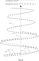
- Figure 8 illustrates an exemplary application of sway control on a load being lifted to a helicopter in accordance with aspects of the disclosure.
- Figure 8 illustrates an exemplary load path 802 that a load may take while being lifted by the hoist system 101 of the helicopter 100.
- the load path 802 is swaying or oscillating under the helicopter 100 in comparison to a vertical center 804.
- the swaying or oscillating motion of the load may be due to the highly dynamic environment that includes or is subjected to various forces, movements, and/or the like.
- the hoist system 101 may obtain aircraft and load measurements that include one or more of the outputs from the load measurement sensors such as the load cell 306, the cable movement measurement sensors such as the distance sensor 320, the cable-payout and direction detector 122 and/or the range-measuring equipment 120, the aircraft movement measurement sensors such as the movement sensor 322, the airspeed measurement sensors, other flight dynamics sensors, and/or the like.
- the load measurement sensors such as the load cell 306, the cable movement measurement sensors such as the distance sensor 320, the cable-payout and direction detector 122 and/or the range-measuring equipment 120, the aircraft movement measurement sensors such as the movement sensor 322, the airspeed measurement sensors, other flight dynamics sensors, and/or the like.
- the hoist system 101 may determine appropriate controls for the motor 110 based at least in part on the output from the sensors and the human input.
- the sway control process (Box 700) may determine appropriate speed for the motor 110 currently lifting the load.
- the hoist system 101 may determine appropriate deceleration for the motor 110 currently lifting the load.
- the hoist system 101 may determine appropriate acceleration for the motor 110 currently lifting the load.
- the hoist system 101 may adjust reeling speed.
- the hoist system 101 may determine the appropriate control for the motor 110 currently lifting the load based on the algorithm or the artificial intelligence as a function of the aircraft and load measurements received and the human input.
- the hoist system 101 may actuate the motor 110 by sending control signals to the motor 110 to lift the load to reduce sway, to reduce oscillation, with a reduced sway, and/or reduced oscillation to ensure safe operation of the aircraft and safe lifting of the load.
- the hoist system 101 may command the motor 110 to adjust the lift velocity of the load.
- the amount of adjustment to the motor 110 may be determined based on the algorithm or the artificial intelligence as a function of the aircraft and load measurements received as described herein.
- the hoist system 101 may actuate the motor 110 by sending control signals to the motor 110 to lift the load to reduce sway, to reduce oscillation, with a reduced sway, and/or reduced oscillation to ensure safe operation of the aircraft and safe lifting of the load.
- the hoist system 101 may command the motor 110 to accelerate the lift velocity 808 (as indicated by the dashed line) of the load. Thereafter, when the hoist system 101 determines that the load is swinging away 810 from the vertical center 804, the hoist system 101 may command the motor 110 to decelerate the lift velocity 812 (as indicated by the dotted line) of the load.
- the amount of acceleration, deceleration, and velocity of the lift provided by the motor 110 may be determined based on the algorithm or the artificial intelligence as a function of the aircraft and load measurements received as described herein.
- the hoist system 101 may actuate the motor 110 by sending control signals to the motor 110 to lift the load to reduce sway, to reduce oscillation, with a reduced sway, and/or reduced oscillation to ensure safe operation of the aircraft and safe lifting of the load.
- the disclosure is not limited to this exemplary aspect.
- the hoist system 101 may actuate the motor 110 to control lift velocity, acceleration, deceleration, and/or the like in response to an algorithm that may be more complex and the adjustments may be made at extremes of an arc of oscillation, a center of an arc of oscillation, and/or at locations between the extremes and center.
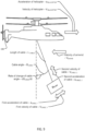
- Figure 9 illustrates a free body diagram of the helicopter hoist system according to an aspect of the disclosure.
- Figure 9 illustrates exemplary dynamic factors that are utilized by the hoist system 101 and the sway control process (Box 700) to reduce sway and/or oscillation.
- the dynamic factors include one or more of a Velocity of helicopter - V HELICOPTER , an Acceleration of helicopter - a HELICOPTER , a Velocity of air/wind - V air/wind , a Cable angle - ⁇ CABLE , a Rate of change of cable angle - d ⁇ CABLE /dt, a Length of cable - L CABLE , a First velocity of cable - V CABLE, 1 , a Second velocity of cable - V CABLE, 2 , a First acceleration of cable - a CABLE, 1 , a Second acceleration of cable - a CABLE, 2 , and a Mass of load - M LOAD .
- Each of the dynamic factors being obtained by one or more sensors described in the disclosure. Thereafter, the sway control process (Box 700) operates based on one or more these dynamic factors obtained by the one or more sensors as described herein.
- the disclosure has set forth a system and process to control the sway of the load and an associated portion of the lifting device to ensure safe operation of the aircraft and a safety of the load.
- the system and process of the disclosure limits uncontrolled oscillations and spin via the use of an electronic control module.
- the system and process of the disclosure has disclosed that oscillation may be mitigated by automatic adjustments to pay-in commands in order to remove human factors which may contribute to excessive oscillations.
- the various aspects of the disclosure are configured to ensure compliance with Federal Aviation Regulations (FARs) for external cargo operations.
- FARs Federal Aviation Regulations
- the various aspects of the disclosure are configured to ensure compliance with FARs for both "Human External Cargo” (HEC) and “Non Human External Cargo” (NHEC) including 14 C.F.R. 29.865 and in addition or in substitution of listed objects (load), which could be hoisted by aspects of the disclosure.
- the illustrated structure is a logical structure and not a physical one. Accordingly, the illustrated modules can be implemented by employing various hardware and software components. In addition, two or more of the logical components can be implemented as a single module that provides functionality for both components. In one aspect, the components are implemented as software program modules.
- the disclosure may be implemented in any type of computing devices, such as, e.g., a desktop computer, personal computer, a laptop/mobile computer, a personal data assistant (PDA), a mobile phone, a tablet computer, cloud computing device, and the like, with wired/wireless communications capabilities via the communication channels.
- computing devices such as, e.g., a desktop computer, personal computer, a laptop/mobile computer, a personal data assistant (PDA), a mobile phone, a tablet computer, cloud computing device, and the like, with wired/wireless communications capabilities via the communication channels.
- PDA personal data assistant
- the methods described herein are intended for operation with dedicated hardware implementations including, but not limited to, PCs, PDAs, semiconductors, application specific integrated circuits (ASIC), programmable logic arrays, cloud computing devices, and other hardware devices constructed to implement the methods described herein.
- dedicated hardware implementations including, but not limited to, PCs, PDAs, semiconductors, application specific integrated circuits (ASIC), programmable logic arrays, cloud computing devices, and other hardware devices constructed to implement the methods described herein.
- a tangible storage medium such as: a magnetic medium such as a disk or tape; a magneto-optical or optical medium such as a disk; or a solid state medium such as a memory card or other package that houses one or more read-only (non-volatile) memories, random access memories, or other re-writable (volatile) memories.
- a digital file attachment to email or other self-contained information archive or set of archives is considered a distribution medium equivalent to a tangible storage medium. Accordingly, the disclosure is considered to include a tangible storage medium or distribution medium, as listed herein and including art-recognized equivalents and successor media, in which the software implementations herein are stored.
- the various aspects of the disclosure may be implemented in a non-generic computer implementation. Moreover, the various aspects of the disclosure set forth herein improve the functioning of the system as is apparent from the disclosure hereof. Furthermore, the various aspects of the disclosure involve computer hardware that it specifically programmed to solve the complex problem addressed by the disclosure. Accordingly, the various aspects of the disclosure improve the functioning of the system overall in its specific implementation to perform the process set forth by the disclosure and as defined by the claims.
- aspects of the disclosure may be implemented in any type of computing devices, such as, e.g., a desktop computer, personal computer, a laptop/mobile computer, a personal data assistant (PDA), a mobile phone, a tablet computer, cloud computing device, and the like, with wired/wireless communications capabilities via the communication channels.
- computing devices such as, e.g., a desktop computer, personal computer, a laptop/mobile computer, a personal data assistant (PDA), a mobile phone, a tablet computer, cloud computing device, and the like, with wired/wireless communications capabilities via the communication channels.
- PDA personal data assistant
- the global navigation satellite system may include a device and/or system that may estimate its location based, at least in part, on signals received from space vehicles (SVs).
- a device and/or system may obtain "pseudorange" measurements including approximations of distances between associated SVs and a navigation satellite receiver.
- a pseudorange may be determined at a receiver that is capable of processing signals from one or more SVs as part of a Satellite Positioning System (SPS).
- SPS Satellite Positioning System
- Such an SPS may comprise, for example, a Global Positioning System (GPS), Galileo, Glonass, to name a few, or any SPS developed in the future.
- GPS Global Positioning System
- Galileo Galileo
- Glonass Glonass
- a satellite navigation receiver may obtain pseudorange measurements to three or more satellites as well as their positions at time of transmitting. Knowing the SV orbital parameters, these positions can be calculated for any point in time. A pseudorange measurement may then be determined based, at least in part, on the time a signal travels from an SV to the receiver, multiplied by the speed of light. While techniques described herein may be provided as implementations of location determination in GPS and/or Galileo types of SPS as specific illustrations according to particular examples, it should be understood that these techniques may also apply to other types of SPS, and that claimed subject matter is not limited in this respect.
- aspects of the disclosure may include communication channels that may be any type of wired or wireless electronic communications network, such as, e.g., a wired/wireless local area network (LAN), a wired/wireless personal area network (PAN), a wired/wireless home area network (HAN), a wired/wireless wide area network (WAN), a campus network, a metropolitan network, an enterprise private network, a virtual private network (VPN), an internetwork, a backbone network (BBN), a global area network (GAN), the Internet, an intranet, an extranet, an overlay network, Near field communication (NFC), a cellular telephone network, a Personal Communications Service (PCS), using known protocols such as the Global System for Mobile Communications (GSM), CDMA (Code-Division Multiple Access), GSM/EDGE and UMTS/HSPA network technologies, Long Term Evolution (LTE), 5G (5th generation mobile networks or 5th generation wireless systems), WiMAX, HSPA + , W-CDMA (Wideband Code-Division
Landscapes
- Engineering & Computer Science (AREA)
- Mechanical Engineering (AREA)
- Aviation & Aerospace Engineering (AREA)
- Control And Safety Of Cranes (AREA)
- Control Of Position, Course, Altitude, Or Attitude Of Moving Bodies (AREA)
Description
- This application claims the benefit of
U.S. Provisional Application No. 62/837,909 filed on April 24, 2019 - The disclosure relates to a hoist system for sway control. The disclosure further relates to a hoist process for sway control. The disclosure further relates to an airborne hoist system for sway control. The disclosure further relates to an airborne hoist process for sway control. The disclosure further relates to an aircraft mounted hoist system for sway control. The disclosure further relates to an aircraft mounted hoist process for sway control.
- Helicopter hoist equipment typically includes a lifting device such as a hoist, which is attached to the helicopter, a hoist cable, and a hook located at a distal end of the hoist cable for direct or indirect attachment to a person, animal, and/or object (load) for rescue, transport, lift, and/or the like. The helicopter hoist equipment usually has a rotary drum for winding in and out the hoist cable that serves to lift or transport the load. A crew member in the helicopter typically controls the helicopter hoist equipment including raising and lowering of the hook.
- The environment in which the helicopter or other aircraft operates as well as the lifting device and the load that is being lifted is highly dynamic and includes or is subjected to various forces, accelerations, movements, and/or the like. A common issue with this environment is that the load may sway or oscillate back and forth, side to side, or combination thereof below the helicopter presenting a risk to safe operation of the helicopter as well as presenting a safety issue for the load.
-
US2016/009393 describes a helicopter-hoist system. The system may include: hoist equipment, illumination systems, range-measuring equipment, camera(s), communication systems, display devices, processing/control systems including image-processing systems, and power-management systems. The system may also include a smart-hook for measuring a load on the hook. Based on the measured load on the cable, the lighting may be illuminated in different manners. In another aspect, the system may communicate with display devices, which render images of a mission to helicopter crew members or other observers. Measured parameters appurtenant to the mission-such as the weight of the load, height of the smart-hook above a surface, altitude of the aircraft, distance between the aircraft and end of the hook, location of the hook in three-dimensional space, forces on the hook and cable, and other mission-critical information-may be overlaid, or rendered proximate to the real images to provide crew members with a full understanding of a mission. -
EP3428114 discloses a self-homing hoist including a controller configured to initiate a self-homing process to return the hook assembly to a homed position in response to each of at least one homing factor being true. Each homing factor is true or false based on a comparison of the current condition, determined by a plurality of sensors, of the homing factor with a threshold requirement. If the current condition satisfies the threshold requirement, then the homing factor is true. If the current condition does not satisfy the threshold requirement, then the homing factor is false. Where all homing factors are true, the controller can initiate the self-homing process by activating a hoist motor to drive the cable drum and reel the hook assembly into the homed position. -
US2018/237276 presents an unmanned aerial vehicle (UAV) including a winch system, wherein the winch system includes a single winch line, wherein a payload is suspended from a first end of the winch line, and the winch system is controllable to vary the rate of ascent of the payload to the UAV, and a control system including a processor and program instructions stored in a non-transitory computer readable medium and executable by the processor to control the winch, the control system configured to (a) receive data regarding oscillations of the payload, and (b) operate the winch system to vary a retraction rate of the winch line to damp oscillations of the payload during ascent of the payload to the UAV. - Accordingly, a system and process to control the sway of the load and an associated portion of the lifting device is needed to ensure safe operation of the aircraft and a safety of the load.
- According to an aspect of the invention there is provided an aircraft hoist system as set out in the appended
independent claim 1. According to a further aspect of the invention there is provided a method of controlling an aircraft hoist system as set out in the appendedindependent claim 2. - There has thus been outlined, rather broadly, certain aspects of the disclosure in order that the detailed description thereof herein may be better understood, and in order that the present contribution to the art may be better appreciated.
- In this respect, before explaining at least one aspect of the disclosure in detail, it is to be understood that the disclosure is not limited in its application to the details of construction and to the arrangements of the components set forth in the following description or illustrated in the drawings. The disclosure is capable of aspects in addition to those described and of being practiced and carried out in various ways. Also, it is to be understood that the phraseology and terminology employed herein, as well as the abstract, are for the purpose of description and should not be regarded as limiting.
- As such, those skilled in the art will appreciate that the conception upon which this disclosure is based may readily be utilized as a basis for the designing of other structures, methods and systems for carrying out the several purposes of the disclosure. It is important, therefore, that the claims be regarded as including such constructions insofar as they do not depart from the scope of the claims.
- Reference herein to an "aspect," "example," or similar formulations means that a particular feature, structure, operation or characteristic described in connection with the "aspect" or "example," is included in at least one implementation in this description. Thus, the appearance of such phrases or formulations is this application may not necessarily all refer to the same example. Further, various particular features, structures, operations, or characteristics may be combined in any suitable manner in or more examples.
-
-
Figure 1 illustrates a helicopter with an exemplary helicopter hoist system in accordance with aspects of the disclosure. -
Figure 2 illustrates an enlarged view of components of the helicopter hoist system shown inFigure 1 . -
Figure 3 illustrates a path of a load being lifted to a helicopter without sway control. -
Figure 4 illustrates a path of a load being lifted to a helicopter without sway control superimposed on a load being lifted to a helicopter with sway control in accordance with aspects of the disclosure. -
Figure 5 illustrates a block diagram illustrating select components of an example helicopter hoist system in accordance with aspects of the disclosure. -
Figure 6 illustrates a block diagram illustrating select components of an example helicopter hoist system in accordance with aspects of the disclosure. -
Figure 7 illustrates an exemplary sway control process on a load being lifted to a helicopter. in accordance with aspects of the disclosure -
Figure 8 illustrates an exemplary application of sway control on a load being lifted to a helicopter in accordance with aspects of the disclosure. -
Figure 9 illustrates a free body diagram of the helicopter hoist system according to an aspect of the disclosure. - The disclosure will now be described with reference to the drawing figures, in which like reference numerals refer to like parts throughout. Aspects of the disclosure advantageously provide a hoist system and hoist process for sway control.
-
Figure 1 shows a helicopter with an exemplary helicopter hoist system in accordance with aspects of the disclosure. In particular,Figure 1 shows ahelicopter 100 with ahoist system 101, which may be used for search and rescue missions, transport missions, combat insertion missions, combat extraction missions, and/or the like. In certain aspects, thehoist system 101 may be implemented as a Helicopter Flight Rescue System (HFRS), a Helicopter External Transport System (HETS), and/or the like. As shown inFigure 1 , thehoist system 101 may be positioned on an upper side of the aircraft, and may be attached directly or indirectly to thehelicopter 100. In other aspects, thehoist system 101 may be mounted to a bottom of thehelicopter 100, may be mounted to a side of thehelicopter 100, may be mounted internally to thehelicopter 100, and/or the like. - Although
Figure 1 depicts a helicopter as the exemplary aircraft, thehoist system 101 and its associated principles/methodologies described herein, are not limited to helicopters, and may be applied to any airborne platform. For example, thehoist system 101 may be attached directly or indirectly to a cargo helicopter (not shown), such as mounted underneath an aircraft fuselage, mounted to a tilt rotor aircraft, aerial crane, flying crane and/or the like. Thehoist system 101 may also be coupled to an autonomous or remote controlled aircraft, such as an unmanned aerial vehicle, unmanned aircraft system (UAV/UAS), a drone, fixed wing aircraft, and the like. Of course, thehoist system 101 may also be implemented in static configurations, non-aircraft based configurations, and/or the like. - Referring to
Figure 1 , thehoist system 101 includes ahook 102 and acable 104. Thehook 102 may be positioned between thecable 104 and ahook portion 106. That is, thehook 102 may be connected to thecable 104 at its upper end, and may be connected to the hook portion 106 (or another object) on its lower end. As appreciated by one skilled in the art with the benefit of this disclosure, thehook 102 may be connected directly or indirectly to thecable 104 and thehook portion 106. For instance, as shown inFigure 1 , a spring-interface device 108 may be connected between thecable 104 and thehook 102. In other aspects, thecable 104 may be connected directly to thehook portion 106. In other aspects, thecable 104 may be connected to thehook portion 106 through the spring-interface device 108. -
Figure 2 illustrates an enlarged view of components of the helicopter hoist system shown inFigure 1 . In particular,Figure 2 illustrates an enlarged view of the hoistsystem 101 shown inFigure 1 , with thecable 104 in a generally retracted position. The hoistsystem 101 may include aframe 103 on which the hoist equipment (i.e., thecable 104, thehook 102, thehook portion 106, and/or a motor 110). The hoistsystem 101 may include anelectronic system 114 that may include a housing. Theelectronic system 114 may include lighting, lighting systems, lasers, laser systems, cameras, camera systems, communication systems, communication equipment, electronics and processing equipment, and/or the like. - The hoist
system 101 includes amotor 110. In one example, themotor 110 may be a brushless motor, which may provide smoother raising and lowering of thecable 104. In another aspect, themotor 110 may include a high-performance variable-speed brushless permanent magnet rotary servomotor, with Universal AC or DC power input. In some aspects, the torque output may range between 5.6 Nm and 13.9 Nm. As appreciated by those skilled in the art, the torque range may vary and may be less than or more than 5.6 Nm and 13.9 Nm. In addition, any suitable motor or motors may be implemented as part of the hoist equipment. Additionally, the hoistsystem 101 may include a transmission, a rotary drum, and/or the like. - The
electronic system 114 also may include a host of other electronic equipment, which are not shown inFigure 2 , but are described in more detail below including communication systems, antenna, processing/control systems including image-processing systems, power-management systems, control systems, motor control systems, sensor systems, and/or the like. -
Figure 3 illustrates a path of a load being lifted to a helicopter without sway control. In particular,Figure 3 illustrates thehelicopter 100 lifting a load (not shown) that is attached to thecable 104. In this regard,Figure 3 illustrates thepath 302 the load makes as it is lifted to thehelicopter 100 without sway control. In this regard, thepath 302 illustrates substantial sway and/or oscillation and thepath 302 approaches and at times exceeds a 30° angle shown byline 304 as illustrated inFigure 3 as the load is lifted from the ground 360 to thehelicopter 100. The operation illustrated inFigure 3 presents a risk to safe operation of thehelicopter 100 as well as presenting a safety issue for the load. -
Figure 4 illustrates a path of a load being lifted to a helicopter without sway control superimposed on a load being lifted to a helicopter with sway control in accordance with aspects of the disclosure. In particular,Figure 4 illustrates thehelicopter 100 lifting a load (not shown) on thecable 104. In this regard,Figure 4 illustrates thepath 302 the load makes as it is lifted to thehelicopter 100 without sway control as described above.Figure 4 further illustrates apath 402 the load makes as it is lifted to thehelicopter 100 with sway control implemented as described below. The operation illustrated inFigure 4 utilizing sway control decreases a risk to safe operation of thehelicopter 100 as well as increases a safety for the load. -
Figure 5 illustrates a block diagram illustrating select components of an example helicopter hoist system in accordance with aspects of the disclosure. - The hoist
system 101 may include one or more sensors to measure a load on thecable 104, thehook portion 106, and/or thehook 102. In one aspect, the hoistsystem 101 may include aload cell 306 associated with themotor 110, theframe 103, and/or the like. In one aspect, theload cell 306 may be integrated in thehook 102 and/or thehook portion 106. However, the one or more sensors to measure a load on thecable 104, thehook portion 106, and/or thehook 102 may be implemented using other sensor technology and/or arranged in other locations. - The
load cell 306 may be implemented as a transducer that is used to create an electrical signal whose magnitude is directly proportional to or a function of the force being measured. Theload cell 306 may be implemented as a hydraulic, a pneumatic, and/or a strain gauge load cell. Theload cell 306 measures a force provided by the load. That is, theload cell 306 is positioned in a load path associated with thehook 102, thehook portion 106, and/orcable 104. As appreciated by one skilled in the art after having the benefit of this disclosure, theload cell 306 can have any construction and be positioned inhook 102, thehook portion 106, along cable 104 (Figure 1 ) path, themotor 110, theframe 103, or the like in any suitable manner to acquire load data. In certain aspects, theload cell 306 may measure at least in part roll, pitch, and/or yaw associated with the aircraft and/or thehook 102, thehook portion 106, and/orcable 104. - The hoist
system 101 may include one or more sensors to measure a movement of thecable 104, thehook portion 106, and/or thehook 102 with respect to thehelicopter 100. In one aspect, the hoistsystem 101 may include aposition sensor 308 associated with themotor 110, theframe 103, thecable 104, thehook portion 106, thehook 102, and/or the like. In one aspect, the hoistsystem 101 may associate theposition sensor 308 with themotor 110 and measure movement thecable 104 or the like that may include swaying, oscillation, and/or the like. Theposition sensor 308 may be implemented as Capacitive transducer, Capacitive displacement sensor, Eddy-current sensor, Ultrasonic sensor, Grating sensor, Hall effect sensor, Inductive non-contact position sensors, Laser Doppler vibrometer (optical), Linear variable differential transformer (LVDT), Multi-axis displacement transducer, Photodiode array, Piezo-electric transducer (piezo-electric), Potentiometer, Proximity sensor (optical), Rotary encoder (angular), String potentiometer, string encoder, cable position transducer, Linear encoder, Rotary encoder, and/or the like. - In one aspect, the
position sensor 308 may be integrated in thehook 102 and/or thehook portion 106 and may be implemented as an inertial measurement unit (IMU). In one aspect, thedistance sensor 320 may be integrated in thehook 102 and/or thehook portion 106 and may be implemented as a location determination device implemented as global navigation satellite system (GNSS) receiver. In one aspect, theposition sensor 308 may be integrated in thehook 102 and/or thehook portion 106 and measure swaying and/or oscillation of thehook 102, thecable 104, and/or thehook portion 106. - The hoist
system 101 may include one or more sensors to measure a length or distance of thecable 104, thehook portion 106, and/or thehook 102 from thehelicopter 100. In one aspect, the hoistsystem 101 may include adistance sensor 320 associated with themotor 110, theframe 103, thecable 104, thehook portion 106, thehook 102, and/or the like. In one aspect, the hoistsystem 101 may associate thedistance sensor 320 with themotor 110 and measure rotations of themotor 110 to determine a length of thecable 104 or the like. In one aspect, the hoistsystem 101 may associate thedistance sensor 320 with themotor 110 and determine a length of thecable 104 payout or the like. Thedistance sensor 320 may be implemented as Capacitive transducer, Capacitive displacement sensor, Eddy-current sensor, Ultrasonic sensor, Grating sensor, Hall effect sensor, Inductive non-contact position sensors, Laser Doppler vibrometer (optical), Linear variable differential transformer (LVDT), Multi-axis displacement transducer, Photodiode array, Piezo-electric transducer (piezo-electric), Potentiometer, Proximity sensor (optical), Rotary encoder (angular), String potentiometer, string encoder, cable position transducer, Linear encoder, Rotary encoder, and/or the like. - In one aspect, the
distance sensor 320 may be integrated in thehook 102 and/or thehook portion 106 and may be implemented as an inertial measurement unit (IMU). In one aspect, thedistance sensor 320 may be integrated in thehook 102 and/or thehook portion 106 and may be implemented as a location determination device implemented as global navigation satellite system (GNSS) receiver. In one aspect, the hoistsystem 101 may also include range-measuring equipment 120 (such as a laser-range finder) for determining the distance of thehook 102 from thehelicopter 100, and as well as the distance of objects or ground/water fromhelicopter 100. In one aspect, the hoistsystem 101 may also include a cable-payout anddirection detector 122, which measures the distance thecable 104 is extended and a direction thecable 104 is moving (i.e., up or down). - The hoist
system 101 may include amovement sensor 322 to measure movement of thehelicopter 100. In one aspect, themovement sensor 322 may be implemented as an inertial measurement unit (IMU). In one aspect, themovement sensor 322 may be implemented as a location determination device implemented as global navigation satellite system (GNSS) receiver. In one aspect, themovement sensor 322 may be implemented as an inertial measurement unit (IMU) and a location determination device implemented as global navigation satellite system (GNSS) receiver. In other aspects, the hoistsystem 101 may receive movement information from thehelicopter 100. - The hoist
system 101 may determine an airspeed measurement of thehelicopter 100. In one aspect, the hoistsystem 101 may receive an airspeed measurement from thehelicopter 100. In one aspect, the airspeed measurement may be determined from a pitot-static system. The pitot-static system may include a system of pressure-sensitive instruments that determine an aircraft airspeed, Mach number, altitude, and/or altitude trend. Additionally, the hoistsystem 101 may measure other flight dynamics and/or receive other flight dynamics data from thehelicopter 100 or another associated system. In this regard, the other flight dynamics data may include roll, roll rate, pitch, pitch rate, yaw, yaw rate, and/or the like data. - In some aspects, the
hook 102 may include acontrol system 310. Thecontrol system 310 may be configured to measure and transmit the load on the hook, altitude of the assembly above ground or water, position and/or directionality of the assembly, and/or other information utilizing sensors as described above or other types of sensors known to one of ordinary skill in the art. In some aspects, the load and sensor data may be stored in any suitable-memory-storage device withinhook 102. In one aspect, anantenna 312 together with the transceiver serves as a means for communicating wirelessly between thecontrol system 310 and other systems located inhelicopter 100 or elsewhere utilizing a communication channel as defined herein. A data port may also serve as a means for communicating with other computing devices including memory storage devices. -
Figure 6 illustrates a block diagram illustrating select components of an example helicopter hoist system in accordance with aspects of the disclosure. In particular,Figure 6 is a block diagram illustrating select components of the hoistsystem 101 that facilitate the interoperability of the hoistsystem 101. As shown inFigure 6 , the hoistsystem 101 may include acontrol system 609, which may control and monitor thehook 102 and other systems/devices associated with the hoistsystem 101 as described in the disclosure. - Although the
control system 609 is illustrated as a discrete block, it is appreciated by those skilled in the art with the benefit of this disclosure, that thecontrol system 609 may reside at various times across different components of the hoistsystem 101. For instance, thecontrol system 609 may be implemented and reside as a component of thehook 102, may be also be implemented and reside in theelectronic system 114, across other devices remote from thehook 102 and theelectronic system 114, and/or the like. - Thus, in a general sense, those skilled in the art will recognize that the various control systems described in the hoist
system 101 can be implemented individually or collectively by a wide range of electrical, mechanical, optical, processing (including hardware, software, firmware, and/or virtually any combination thereof), and various combinations of the foregoing. - Furthermore, various elements located in the
hook 102 may communicate viaantenna 312 in thehook 102 with components resident in theelectronic system 114 or other component remote from theelectronic system 114, such as located in thehelicopter 100. Anantenna 611 implemented with a transceiver associated with the hoistsystem 101 may provide a mechanism for transmitting and receiving data to/from thehook 102, and other devices. Thus, even though thecontrol system 310 is shown apart from thecontrol system 609, it is appreciated by those skilled in the art with the benefit of this disclosure that thecontrol system 310 may form an integral part of thecontrol system 609 for the hoistsystem 101. In addition, although wireless communication via antennae is described, it is appreciated that wired communication may be used between thehook 102 and other elements of the hoistsystem 101. - As depicted in
Figure 6 , thecontrol system 609 represents any suitable computer device(s) having one or more processor(s) 604 and the ability to access the computer-readable media 606 to execute instructions or code that controls thehook 102, as well as other devices associated with the hoistsystem 101. The processor(s) 604 may be located in theelectronic system 114 and may be embodied as any suitable electrical circuit, computing processor including special integrated circuits, ASICs, FPGAs, microcontrollers, processor, co-processor, microprocessor, controllers, or other processing means. The processor(s) 604 may also be embedded in thehook 102. - The processor(s) 604 may be distributed in more than one computer system and over a network utilizing a transceiver operating on a communication channel as defined herein (not shown). Examples of the computer systems may include, but are not limited to, a server, personal computer, distributed computer systems, or other computing devices having access to processors and computer-readable medial. Further, although not shown, any number of system busses, communication and peripheral interfaces, input/output devices, and other devices may be included in the control system 609 (including the control system 310), as appreciated by those skilled in the art.
- Still referring to
Figure 6 , the computer-readable media 606 may include any suitable computer-storage media including volatile and non-volatile memory, and any combination thereof. For example, computer storage media includes volatile and non-volatile, removable and non-removable media implemented in any method or technology for storage of information such as computer readable instructions, data structures, program modules, or other data. Computer storage media may further include, but is not limited to, RAM, ROM, EEPROM, flash memory or other memory technology, CD-ROM, digital versatile disks (DVD) or other optical storage, magnetic cassettes, magnetic tape, magnetic disk storage or other magnetic storage devices, or any other non-transitory or non-transmission medium that can be used to store information for access by a computing device. In one aspect, the computer-readable media 606 stores a sway control process (Box 700) as described below. - In other examples, the computer-
readable media 606 may include communication media that may embody computer readable instructions, data structures, program modules, or other data in a modulated data signal, such as a carrier wave, or other transmission mechanism. In one aspect, the computer-readable media 606 may be implemented as a computer program product having instructions and configured to be executed by thecontrol system 609 and/or the processor(s) 604. - Further, the computer-
readable media 606 may be local and/or offsite to computer systems (not shown). For instance, one or more portions of, or all of data or code stored in the computer-readable media 606, may be accessed from a computer-storage medium local to and/or remote to thecontrol system 609, such as from a storage medium connected to a network. - Resident in the computer-
readable media 606 may be one or more operating systems (not shown), and any number of other program applications or modules in the form of computer-executable instructions and/or logic which are executed on the processor(s) 604 to enable processing of data or other functionality. - Still referring to
Figure 6 , thecontrol system 609 may be configured with a sensor-system-control module 608 that may be maintained in the computer-readable media 606. In one example, the sensor-system-control module 608 may be implemented as code in the form of computer-readable instructions that execute on the processor(s) 604. For purposes of illustration, programs and other executable-program modules are illustrated herein as discrete blocks, although it is recognized that such programs and components may reside at various times in different storage components. Further, such code may be implemented as one or more applications or modules, or may be integrated as components within a single application. Such code stored in the computer-readable media 606 may be implemented across one or more computers in a cloud computing environment, on a local device or system, or on a combination of both. The following discussion does not limit the implementation of code stored in the computer-readable media 606 to any particular device or environment. - The sensor-system-
control module 608 may include components contained in the computer-readable media 606. In one example, the sensor-system-control module 608 includes: alighting module 610, a position/load module 612, and adisplay module 614. - In one aspect, the position/
load module 612 facilitates a mode of operation of thecontrol system 609 in which the position/load module 612 monitors measurements made by the load measurement sensors such as theload cell 306, the cable movement measurement sensors such as thedistance sensor 320, the cable-payout anddirection detector 122 and/or the range-measuringequipment 120, the aircraft movement measurement sensors such as themovement sensor 322, airspeed measurement sensors, other flight dynamics sensors, and/or the like. In one aspect, the position/load module 612 facilitates a mode of operation of thecontrol system 609 in which the position/load module 612 monitors measurements made by an inertial measurement unit (IMU) and/or global positioning unit (GPS) (collectively referred to herein as IMS/GPS 602) located in thehook 102 and/or theelectronic system 114. The position/load module 612 may also record these measurements (i.e., data) generated by the IMS/GPS 602, and transmit these measurements to the hoistsystem 101 as well as other monitoring devices, such as located in thehelicopter 100. - The IMS/
GPS 602 may be in communication with the position/load module 612 and enable thecontrol system 609 to monitor a location and/or relative motion of thehook 102 and/or thehook portion 106 in three-dimensional coordinate space relative to the helicopter. - Thus, the combination of one or more of the load measurement sensors such as the
load cell 306, the cable movement measurement sensors such as thedistance sensor 320, the cable-payout anddirection detector 122 and/or the range-measuringequipment 120, the aircraft movement measurement sensors such as themovement sensor 322, airspeed measurement sensors, other flight dynamics sensors, theload cell 306, the IMS/GPS 602 under control of the control system 609 (includingcontrol system 310 individually or in combination withsystem 609 as a whole), and the like allow for complete mapping of thehook 102--and hook load--in 3D coordinate space and relative to the airframe (helicopter and/or hoist). With cable payout information, the hoist cable fleet angle and/or the like may also be calculated. This data may be used to understand the load conditions on the hoist and helicopter airframe. Put differently, the IMS/GPS 602 under control of the control system 609 (including thecontrol system 310 individually or in combination with thesystem 609 as a whole) may allow for mapping of the position, velocity, sway, oscillation, acceleration, and/or the like of thehook 102, thehook portion 106, and/or the load relative to the ground and/or aircraft. - In addition, the IMS/
GPS 602 under control of the control system 609 (including thecontrol system 310 individually or in combination with thesystem 609 as a whole) may use the real-time load and acceleration data from thehook 102 to adjust the payout of the cable 104 (via hoist equipment such as thecable 104, thehook 102, and the motor 110) to actively dampen vibrations imparted to the hoist equipment and aircraft, actively reduce sway to the hoist equipment and aircraft, actively reduce oscillation to the hoist equipment and aircraft, and/or the like. - Thus, this data allows for monitoring health and maintenance of the hoist system, and the number of hoist system cycles, and the ability to predict component wear and plan maintenance. For the helicopter, this data allows for complete dynamic load mapping for the structural design of helicopter hoist mounts/interfaces. Real-time dynamic load information supplied by the
control system 609 also allows for active hoist mounts that optimize the load transfer and energy management between the hook and the helicopter, providing for reduced shock loads on hoist components, helicopter mounts, and any personnel or cargo on the hook. Optimizing the dynamic response of the helicopter and hoist as a system can provide inputs to helicopter-flight controls for an optimized response during load transfer and flight. - The dynamic response of the system may change based on cable length (i.e., pendulum effect on the cable), and the ability to optimize the helicopter system-level response with these sensor inputs may provide for improved flight control and stability during operations and cargo transfers.
-
Figure 7 illustrates an exemplary sway control process on a load being lifted to a helicopter in accordance with aspects of the disclosure. - In particular,
Figure 7 illustrates a sway control process (Box 700) as a collection of blocks in a logical flow graph, which represent a sequence of operations that can be implemented in hardware, software, or a combination thereof. In the context of software, the blocks may represent computer-executable instructions that, when executed by one or more processors, perform the recited operations. Generally, computer-executable instructions may include routines, programs, objects, components, data structures, and/or the like that perform particular functions or implement particular abstract data types. The order in which the operations are described is not intended to be construed as a limitation, and any number of the described blocks can be combined in any order and/or in parallel to implement the process. Also, one or more of the described blocks may be omitted without departing from the scope of the present disclosure. Additionally, it should be noted that the sway control process (Box 700) is merely exemplary and may be modified consistent with the various aspects disclosed herein. - In particular,
Figure 7 illustrates the sway control process (Box 700). In one aspect, the sway control process (Box 700) reduces sway of thecable 104 and the load. In one aspect, the sway control process (Box 700) reduces oscillation of thecable 104 and the load. In one aspect, the sway control process (Box 700) reduces sway and oscillation of thecable 104 and the load. - In one aspect, the sway control process (Box 700) may be stored in the computer-
readable media 606. In one aspect, the sway control process (Box 700) may be executed by thecontrol system 609. In one aspect, the sway control process (Box 700) may be executed by the processor(s) 604. - The sway control process (Box 700) of the disclosure may include determining whether sway control is enabled (box 702). Moreover, one or more proceeding or subsequent processes may also be implemented with determining whether sway control is enabled (box 702) consistent with the disclosure. In one aspect, the sway control process (Box 700) may be enabled or disabled by the pilot. In this regard, the pilot may include an input device such as a switch or the like to manually enable the sway control process (Box 700) and/or disable the sway control process (Box 700). In this regard, the sway control process (Box 700) may be configured to be selectively turned off for mission types which require immediate extraction. In one aspect, the sway control process (Box 700) may be configured to be automatically turned off for mission types which require immediate extraction. In one aspect, the sway control process (Box 700) may be configured to be automatically turned on for mission types which require increased safety. In one aspect, the sway control process (Box 700) may be configured to be automatically turned on or turned off based on information obtained through artificial intelligence.
- The artificial intelligence as described herein may utilize any number of approaches including one or more of cybernetics and brain simulation, symbolic, cognitive simulation, logic-based, anti-logic, knowledge-based, sub-symbolic, embodied intelligence, computational intelligence and soft computing, machine learning and statistics, neural networks, and/or the like. In one aspect, the artificial intelligence may be implemented by the
control system 609, the processor(s) 604, or the like. In one aspect, the artificial intelligence may include inputs from one or more of the load measurement sensors such as theload cell 306, the cable movement measurement sensors such as thedistance sensor 320, the cable-payout anddirection detector 122 and/or the range-measuringequipment 120, the aircraft movement measurement sensors such as themovement sensor 322, airspeed measurement sensors, other flight dynamics sensors, and/or the like. - In one aspect, the sway control process (Box 700) may obtain aircraft and load measurements (Box 704). In one aspect, the sway control process (Box 700) may obtain aircraft and load measurements (Box 704) that include one or more of the outputs from the load measurement sensors such as the
load cell 306, the cable movement measurement sensors such as thedistance sensor 320, the cable-payout anddirection detector 122 and/or the range-measuringequipment 120, the aircraft movement measurement sensors such as themovement sensor 322, the airspeed measurement sensors, other flight dynamics sensors, and/or the like. - In one aspect, the sway control process (Box 700) of the disclosure may include the hoist
system 101 or other components operating to receive human control input (Box 705). The human input may be from movements of controls of an electronic interface from the pilot and/or crew. The movements of the controls may be converted to electronic signals by the hoistsystem 101. The human input may include an indication with respect to a lift direction, a lift velocity, and/or the like. In this regard, the hoistsystem 101 and the sway control process (Box 700) may be configured to modify existing human commands for hoist actuation and hoist movement in terms of scale input, and not directly actuate a hoist motor or movement otherwise. In one aspect, the hoistsystem 101 may be configured to replace the manual controls with an electronic interface. Further in this aspect, the movements of controls of the electronic interface may be converted to electronic signals and the hoistsystem 101 and/or the sway control process (Box 700) may determine how to operate the hoistsystem 101 to provide an ordered response to movements of the controls. - In one aspect, the sway control process (Box 700) may determine appropriate controls for the motor (Box 706). In one aspect, the sway control process (Box 700) may determine appropriate controls for the motor (Box 706) based at least in part on the output from the sensors and the human input. In one aspect, the sway control process (Box 700) may determine appropriate speed for the
motor 110 currently lifting the load. In one aspect, the sway control process (Box 700) may determine appropriate deceleration for themotor 110 currently lifting the load. In one aspect, the sway control process (Box 700) may determine appropriate acceleration for themotor 110 currently lifting the load. In one aspect, the sway control process (Box 700) may determine appropriate velocity or reeling speed for themotor 110 currently lifting the load. - In one aspect, the sway control process (Box 700) may determine the appropriate control for the
motor 110 currently lifting the load based on an algorithm operating as a function of the aircraft and load measurements obtained inbox 704. In certain aspects, the algorithm may be expressed within a finite amount of space and time and in a well-defined formal language for calculating a function of the motor control. In certain aspects, the algorithm may start from an initial state and initial input of the aircraft and load measurements obtained inbox 704. In certain aspects, the algorithm may implement a computation that, when executed, proceeds through a finite number of well-defined successive states, eventually producing control signals for controlling themotor 110. In one aspect, the sway control process (Box 700) may determine the appropriate control for themotor 110 currently lifting the load based on artificial intelligence as a function of the aircraft and load measurements obtained inbox 704. In some aspects, the hoistsystem 101 and/or the sway control process (Box 700) may compare commanded inputs vs calculated controls for themotor 110. In one aspect, the hoistsystem 101 and/or the sway control process (Box 700) may utilize a comparator. - In one aspect, the sway control process (Box 700) may augment and/or actuate the motor 110 (box 708). In this regard, the sway control process (Box 700) may actuate the
motor 110 based on the appropriate controls determined inbox 706. In particular, the sway control process (Box 700) may actuate themotor 110 by sending control signals to themotor 110 to lift the load to reduce sway, to reduce oscillation, with a reduced sway, and/or reduced oscillation to ensure safe operation of the aircraft and safe lifting of the load. -
Figure 8 illustrates an exemplary application of sway control on a load being lifted to a helicopter in accordance with aspects of the disclosure. - In particular,
Figure 8 illustrates anexemplary load path 802 that a load may take while being lifted by the hoistsystem 101 of thehelicopter 100. As noted inFigure 8 , theload path 802 is swaying or oscillating under thehelicopter 100 in comparison to avertical center 804. The swaying or oscillating motion of the load may be due to the highly dynamic environment that includes or is subjected to various forces, movements, and/or the like. - While the load is being lifted to the
helicopter 100, the hoistsystem 101 may obtain aircraft and load measurements that include one or more of the outputs from the load measurement sensors such as theload cell 306, the cable movement measurement sensors such as thedistance sensor 320, the cable-payout anddirection detector 122 and/or the range-measuringequipment 120, the aircraft movement measurement sensors such as themovement sensor 322, the airspeed measurement sensors, other flight dynamics sensors, and/or the like. - The hoist
system 101 may determine appropriate controls for themotor 110 based at least in part on the output from the sensors and the human input. In one aspect, the sway control process (Box 700) may determine appropriate speed for themotor 110 currently lifting the load. In one aspect, the hoistsystem 101 may determine appropriate deceleration for themotor 110 currently lifting the load. In one aspect, the hoistsystem 101 may determine appropriate acceleration for themotor 110 currently lifting the load. In one aspect, the hoistsystem 101 may adjust reeling speed. - In one aspect, the hoist
system 101 may determine the appropriate control for themotor 110 currently lifting the load based on the algorithm or the artificial intelligence as a function of the aircraft and load measurements received and the human input. - In one aspect, the hoist
system 101 may actuate themotor 110 by sending control signals to themotor 110 to lift the load to reduce sway, to reduce oscillation, with a reduced sway, and/or reduced oscillation to ensure safe operation of the aircraft and safe lifting of the load. - In one aspect, when the hoist
system 101 determines that the load is being subjected to sway and/or oscillation, the hoistsystem 101 may command themotor 110 to adjust the lift velocity of the load. The amount of adjustment to themotor 110 may be determined based on the algorithm or the artificial intelligence as a function of the aircraft and load measurements received as described herein. In particular, the hoistsystem 101 may actuate themotor 110 by sending control signals to themotor 110 to lift the load to reduce sway, to reduce oscillation, with a reduced sway, and/or reduced oscillation to ensure safe operation of the aircraft and safe lifting of the load. - According to the invention, when the hoist
system 101 determines that the load is swinging toward 806 thevertical center 804, the hoistsystem 101 may command themotor 110 to accelerate the lift velocity 808 (as indicated by the dashed line) of the load. Thereafter, when the hoistsystem 101 determines that the load is swinging away 810 from thevertical center 804, the hoistsystem 101 may command themotor 110 to decelerate the lift velocity 812 (as indicated by the dotted line) of the load. The amount of acceleration, deceleration, and velocity of the lift provided by themotor 110 may be determined based on the algorithm or the artificial intelligence as a function of the aircraft and load measurements received as described herein. In particular, the hoistsystem 101 may actuate themotor 110 by sending control signals to themotor 110 to lift the load to reduce sway, to reduce oscillation, with a reduced sway, and/or reduced oscillation to ensure safe operation of the aircraft and safe lifting of the load. However, the disclosure is not limited to this exemplary aspect. In particular, the hoistsystem 101 may actuate themotor 110 to control lift velocity, acceleration, deceleration, and/or the like in response to an algorithm that may be more complex and the adjustments may be made at extremes of an arc of oscillation, a center of an arc of oscillation, and/or at locations between the extremes and center. -
Figure 9 illustrates a free body diagram of the helicopter hoist system according to an aspect of the disclosure. In particular,Figure 9 illustrates exemplary dynamic factors that are utilized by the hoistsystem 101 and the sway control process (Box 700) to reduce sway and/or oscillation. The dynamic factors include one or more of a Velocity of helicopter - VHELICOPTER, an Acceleration of helicopter - aHELICOPTER, a Velocity of air/wind - Vair/wind, a Cable angle - ΘCABLE, a Rate of change of cable angle - dΘCABLE/dt, a Length of cable - LCABLE, a First velocity of cable - VCABLE, 1, a Second velocity of cable - VCABLE, 2, a First acceleration of cable - aCABLE, 1, a Second acceleration of cable - aCABLE, 2, and a Mass of load - MLOAD. Each of the dynamic factors being obtained by one or more sensors described in the disclosure. Thereafter, the sway control process (Box 700) operates based on one or more these dynamic factors obtained by the one or more sensors as described herein. - Accordingly, the disclosure has set forth a system and process to control the sway of the load and an associated portion of the lifting device to ensure safe operation of the aircraft and a safety of the load. In particular, the system and process of the disclosure limits uncontrolled oscillations and spin via the use of an electronic control module. Furthermore, the system and process of the disclosure has disclosed that oscillation may be mitigated by automatic adjustments to pay-in commands in order to remove human factors which may contribute to excessive oscillations.
- Additionally, the various aspects of the disclosure are configured to ensure compliance with Federal Aviation Regulations (FARs) for external cargo operations. In particular, the various aspects of the disclosure are configured to ensure compliance with FARs for both "Human External Cargo" (HEC) and "Non Human External Cargo" (NHEC) including 14 C.F.R. 29.865 and in addition or in substitution of listed objects (load), which could be hoisted by aspects of the disclosure.
- As may be appreciated by those skilled in the art, the illustrated structure is a logical structure and not a physical one. Accordingly, the illustrated modules can be implemented by employing various hardware and software components. In addition, two or more of the logical components can be implemented as a single module that provides functionality for both components. In one aspect, the components are implemented as software program modules.
- The disclosure may be implemented in any type of computing devices, such as, e.g., a desktop computer, personal computer, a laptop/mobile computer, a personal data assistant (PDA), a mobile phone, a tablet computer, cloud computing device, and the like, with wired/wireless communications capabilities via the communication channels.
- Further in accordance with various aspects of the disclosure, the methods described herein are intended for operation with dedicated hardware implementations including, but not limited to, PCs, PDAs, semiconductors, application specific integrated circuits (ASIC), programmable logic arrays, cloud computing devices, and other hardware devices constructed to implement the methods described herein.
- It should also be noted that the software implementations of the disclosure as described herein are optionally stored on a tangible storage medium, such as: a magnetic medium such as a disk or tape; a magneto-optical or optical medium such as a disk; or a solid state medium such as a memory card or other package that houses one or more read-only (non-volatile) memories, random access memories, or other re-writable (volatile) memories. A digital file attachment to email or other self-contained information archive or set of archives is considered a distribution medium equivalent to a tangible storage medium. Accordingly, the disclosure is considered to include a tangible storage medium or distribution medium, as listed herein and including art-recognized equivalents and successor media, in which the software implementations herein are stored.
- Additionally, the various aspects of the disclosure may be implemented in a non-generic computer implementation. Moreover, the various aspects of the disclosure set forth herein improve the functioning of the system as is apparent from the disclosure hereof. Furthermore, the various aspects of the disclosure involve computer hardware that it specifically programmed to solve the complex problem addressed by the disclosure. Accordingly, the various aspects of the disclosure improve the functioning of the system overall in its specific implementation to perform the process set forth by the disclosure and as defined by the claims.
- Aspects of the disclosure may be implemented in any type of computing devices, such as, e.g., a desktop computer, personal computer, a laptop/mobile computer, a personal data assistant (PDA), a mobile phone, a tablet computer, cloud computing device, and the like, with wired/wireless communications capabilities via the communication channels.
- According to an example, the global navigation satellite system (GNSS) may include a device and/or system that may estimate its location based, at least in part, on signals received from space vehicles (SVs). In particular, such a device and/or system may obtain "pseudorange" measurements including approximations of distances between associated SVs and a navigation satellite receiver. In a particular example, such a pseudorange may be determined at a receiver that is capable of processing signals from one or more SVs as part of a Satellite Positioning System (SPS). Such an SPS may comprise, for example, a Global Positioning System (GPS), Galileo, Glonass, to name a few, or any SPS developed in the future. To determine its location, a satellite navigation receiver may obtain pseudorange measurements to three or more satellites as well as their positions at time of transmitting. Knowing the SV orbital parameters, these positions can be calculated for any point in time. A pseudorange measurement may then be determined based, at least in part, on the time a signal travels from an SV to the receiver, multiplied by the speed of light. While techniques described herein may be provided as implementations of location determination in GPS and/or Galileo types of SPS as specific illustrations according to particular examples, it should be understood that these techniques may also apply to other types of SPS, and that claimed subject matter is not limited in this respect.
- Aspects of the disclosure may include communication channels that may be any type of wired or wireless electronic communications network, such as, e.g., a wired/wireless local area network (LAN), a wired/wireless personal area network (PAN), a wired/wireless home area network (HAN), a wired/wireless wide area network (WAN), a campus network, a metropolitan network, an enterprise private network, a virtual private network (VPN), an internetwork, a backbone network (BBN), a global area network (GAN), the Internet, an intranet, an extranet, an overlay network, Near field communication (NFC), a cellular telephone network, a Personal Communications Service (PCS), using known protocols such as the Global System for Mobile Communications (GSM), CDMA (Code-Division Multiple Access), GSM/EDGE and UMTS/HSPA network technologies, Long Term Evolution (LTE), 5G (5th generation mobile networks or 5th generation wireless systems), WiMAX, HSPA+, W-CDMA (Wideband Code-Division Multiple Access), CDMA2000 (also known as C2K or IMT Multi-Carrier (IMT-MC)), Wireless Fidelity (Wi-Fi), Bluetooth, and/or the like, and/or a combination of two or more thereof. The NFC standards cover communications protocols and data exchange formats, and are based on existing radio-frequency identification (RFID) standards including ISO/IEC 14443 and FeliCa. The standards include ISO/IEC 18092[3] and those defined by the NFC Forum
- Further, since numerous modifications and variations will readily occur to those skilled in the art, it is not desired to limit the disclosure to the exact construction and operation illustrated and described, and, accordingly, all suitable modifications may be resorted insofar as they fall within the scope of the claims.
Claims (2)
- An aircraft hoist system (101), comprising:hoist equipment adapted for use with an aircraft (100), the hoist equipment including a motor (110), a cable (104), and a hook portion (102);at least one sensor (306, 308, 320, 322) configured to obtain measurements comprising at least one of following: a load measurement, a cable position measurement, a cable movement measurement, an aircraft movement measurement, and an airspeed measurement;a processor (604) configured to analyze the measurements from the at least one sensor (306, 308, 320, 322);wherein the processor (604) is configured to determine control for the motor (110) as a function of the measurements from the at least one sensor (306, 308, 320, 322); andthe processor (604) is configured to actuate the motor (110) to reduce sway and/or oscillations of a load and the cable (104) while lifting the load,wherein the at least one sensor (306, 308, 320, 322) comprises at least one of the following: a load measurement sensor, a cable movement measurement sensor, a cable position measurement sensor, an aircraft movement measurement sensor, and an airspeed measurement sensor;wherein the processor (604) is configured to determine a lift velocity for the motor (110) currently lifting the load, a lift acceleration for the motor (110) currently lifting the load, and a lift deceleration for the motor (110) currently lifting the load;wherein the measurements from at least one sensor (306, 308, 320, 322) comprises measuring with the at least one sensor (306, 308, 320, 322) at least one of following: a load measurement, a cable position measurement, a cable movement measurement;wherein the processor (604) is configured to command the motor (110) to accelerate a lift velocity when the load is swinging toward a vertical center; andwherein the processor (604) is configured to command the motor (110) to decelerate a lift velocity when the load is swinging away from a vertical center.
- A method of controlling an aircraft hoist system (101), comprising:implementing hoist equipment adapted for use with an aircraft (100), the hoist equipment including a motor (110), a cable (104), and a hook portion (104);obtaining measurements from at least one sensor (306, 308, 320, 322) by measuring with the at least one sensor at least one of following: a load measurement, a cable position measurement, a cable movement measurement, an aircraft movement measurement, and an airspeed measurement;analyzing the measurements with a processor (604) from the at least one sensor (306, 308, 320, 322);the method further comprising the steps of:determining with the processor (604) a control for controlling the motor (110) as a function of the measurements from the at least one sensor (306, 308, 320, 322); andsending control signals to the motor (110) to reduce sway and/or oscillations of the cable (104) while lifting a load; andwherein the at least one sensor (306, 308, 320, 322) comprises at least one of the following: a load measurement sensor, a cable movement measurement sensor, a cable position measurement sensor, an aircraft movement measurement sensor, and an airspeed measurement sensor;wherein the processor (604) is configured to determine a lift velocity for the motor (110) currently lifting the load, a lift acceleration for the motor (110) currently lifting the load, and a lift deceleration for the motor (110) currently lifting the load;wherein the measurements from at least one sensor (306, 308, 320, 322) comprises measuring with the at least one sensor (306, 308, 320, 322) at least one of following: a load measurement, a cable position measurement, a cable movement measurement;wherein the processor (604) is configured to command the motor (110) to accelerate a lift velocity when the load is swinging toward a vertical center; andwherein the processor (604) is configured to command the motor (110) to decelerate a lift velocity when the load is swinging away from a vertical center.
Applications Claiming Priority (2)
| Application Number | Priority Date | Filing Date | Title |
|---|---|---|---|
| US201962837909P | 2019-04-24 | 2019-04-24 | |
| PCT/US2020/029729 WO2020219818A1 (en) | 2019-04-24 | 2020-04-24 | Hoist system and process for sway control |
Publications (3)
| Publication Number | Publication Date |
|---|---|
| EP3959131A1 EP3959131A1 (en) | 2022-03-02 |
| EP3959131A4 EP3959131A4 (en) | 2022-12-28 |
| EP3959131B1 true EP3959131B1 (en) | 2025-03-26 |
Family
ID=72941825
Family Applications (1)
| Application Number | Title | Priority Date | Filing Date |
|---|---|---|---|
| EP20794786.2A Active EP3959131B1 (en) | 2019-04-24 | 2020-04-24 | Hoist system and process for sway control |
Country Status (3)
| Country | Link |
|---|---|
| US (1) | US11760486B2 (en) |
| EP (1) | EP3959131B1 (en) |
| WO (1) | WO2020219818A1 (en) |
Families Citing this family (10)
| Publication number | Priority date | Publication date | Assignee | Title |
|---|---|---|---|---|
| US11267555B2 (en) * | 2018-01-08 | 2022-03-08 | GEOSAT Aerospace & Technology | Methods and unmanned aerial vehicles for longer duration flights |
| CN111153328B (en) * | 2020-04-02 | 2020-07-24 | 上海驭矩信息科技有限公司 | Anti-swing control method and system of hoisting system based on L QR |
| US12319427B2 (en) * | 2021-04-23 | 2025-06-03 | Arizona Board Of Regents On Behalf Of Arizona State University | Systems and methods for autonomous vision-guided object collection from water surfaces with a customized multirotor |
| CA3219996A1 (en) * | 2021-05-25 | 2022-12-01 | Derek SIKORA | Long line loiter apparatus, system, and method |
| US12077293B2 (en) * | 2021-09-16 | 2024-09-03 | Insitu, Inc. | Methods and apparatus to guide an unmanned aerial vehicle for recovery thereof |
| KR102499985B1 (en) * | 2022-10-04 | 2023-02-16 | 주식회사 쉐카이나 | Safety system for Accident prevention with Camera |
| US12459793B2 (en) | 2022-11-14 | 2025-11-04 | Hornet Acquisitionco, Llc | Method to detect homing loads in rescue hoist and winch assemblies |
| US12466704B2 (en) | 2022-11-14 | 2025-11-11 | Hornet Acquisitionco, Llc | Homing load detecting device for rescue hoist and winch assemblies |
| TR2023007843A1 (en) * | 2023-07-05 | 2025-01-21 | Tusas Tuerk Havacilik Ve Uzay Sanayii Anonim Sirketi | A payload transport system |
| US20250368325A1 (en) * | 2024-06-03 | 2025-12-04 | Rockwell Collins, Inc. | Hoisting flight director mode |
Family Cites Families (14)
| Publication number | Priority date | Publication date | Assignee | Title |
|---|---|---|---|---|
| US3510107A (en) * | 1968-01-11 | 1970-05-05 | United Aircraft Corp | Multiple hoist synchronization system |
| JP3241591B2 (en) * | 1996-04-10 | 2001-12-25 | 株式会社奥村組 | Crane control method |
| US7832126B2 (en) * | 2007-05-17 | 2010-11-16 | Siemens Industry, Inc. | Systems, devices, and/or methods regarding excavating |
| CL2012000933A1 (en) * | 2011-04-14 | 2014-07-25 | Harnischfeger Tech Inc | A method and a cable shovel for the generation of an ideal path, comprises: an oscillation engine, a hoisting engine, a feed motor, a bucket for digging and emptying materials and, positioning the shovel by means of the operation of the lifting motor, feed motor and oscillation engine and; a controller that includes an ideal path generator module. |
| GB201210057D0 (en) * | 2012-06-07 | 2012-07-25 | Jaguar Cars | Crane and related method of operation |
| US9115581B2 (en) * | 2013-07-09 | 2015-08-25 | Harnischfeger Technologies, Inc. | System and method of vector drive control for a mining machine |
| US9422139B1 (en) | 2014-05-19 | 2016-08-23 | Google Inc. | Method of actively controlling winch swing via modulated uptake and release |
| CA2953512A1 (en) * | 2014-06-25 | 2015-12-30 | Siemens Industry, Inc. | Operator assist features for excavating machines based on perception system feedback |
| WO2016007796A1 (en) * | 2014-07-10 | 2016-01-14 | Breeze-Eastern Corporation | Helicopter hoist systems, devices, and methodologies |
| FI20155599A (en) * | 2015-08-21 | 2017-02-22 | Konecranes Global Oy | Control of a lifting device |
| CN107034944B (en) * | 2015-12-15 | 2021-05-25 | 久益环球地表采矿公司 | System and method for estimating payload of industrial machinery |
| CA2978389C (en) * | 2016-09-08 | 2025-12-09 | Joy Global Surface Mining Inc | System and method for semi-autonomous control of an industrial machine |
| US10843905B2 (en) * | 2017-04-04 | 2020-11-24 | Summation Labs, LLC | Systems and methods for slung load stabilization |
| US10252894B2 (en) | 2017-07-10 | 2019-04-09 | Goodrich Corporation | Self-homing hoist |
-
2020
- 2020-04-24 WO PCT/US2020/029729 patent/WO2020219818A1/en not_active Ceased
- 2020-04-24 US US16/857,947 patent/US11760486B2/en active Active
- 2020-04-24 EP EP20794786.2A patent/EP3959131B1/en active Active
Also Published As
| Publication number | Publication date |
|---|---|
| US11760486B2 (en) | 2023-09-19 |
| US20210197970A1 (en) | 2021-07-01 |
| WO2020219818A1 (en) | 2020-10-29 |
| EP3959131A1 (en) | 2022-03-02 |
| EP3959131A4 (en) | 2022-12-28 |
Similar Documents
| Publication | Publication Date | Title |
|---|---|---|
| US11760486B2 (en) | Hoist system and process for sway control | |
| CN112638770B (en) | safe unmanned aerial vehicle | |
| AU2021369576B2 (en) | Systems and methods for battery capacity management in a fleet of UAVs | |
| EP4149840B1 (en) | Systems and methods for autonomous airworthiness pre-flight checks for uavs | |
| US12054256B2 (en) | UAV with upper door including winch and method of operation | |
| US11767111B1 (en) | Slotted receptacle for payload handle to secure payload within a UAV | |
| US12179902B2 (en) | Smart cargo bay door(s) for a UAV | |
| US12168512B2 (en) | UAV with open cargo bay and method of operation | |
| US20220315397A1 (en) | Hoist system and process implementing slip detection | |
| AU2022252791B2 (en) | Semantic abort of unmanned aerial vehicle deliveries | |
| AU2022252792B2 (en) | Unmanned aerial vehicle trajectories for nudging and un-nudging | |
| US20240140587A1 (en) | UAV Having Lower Cargo Bay Door(s) | |
| CA3219996A1 (en) | Long line loiter apparatus, system, and method | |
| US20260131890A1 (en) | UAV with Open Cargo Bay and Method of Operation |
Legal Events
| Date | Code | Title | Description |
|---|---|---|---|
| STAA | Information on the status of an ep patent application or granted ep patent |
Free format text: STATUS: THE INTERNATIONAL PUBLICATION HAS BEEN MADE |
|
| PUAI | Public reference made under article 153(3) epc to a published international application that has entered the european phase |
Free format text: ORIGINAL CODE: 0009012 |
|
| STAA | Information on the status of an ep patent application or granted ep patent |
Free format text: STATUS: REQUEST FOR EXAMINATION WAS MADE |
|
| 17P | Request for examination filed |
Effective date: 20211123 |
|
| AK | Designated contracting states |
Kind code of ref document: A1 Designated state(s): AL AT BE BG CH CY CZ DE DK EE ES FI FR GB GR HR HU IE IS IT LI LT LU LV MC MK MT NL NO PL PT RO RS SE SI SK SM TR |
|
| DAV | Request for validation of the european patent (deleted) | ||
| DAX | Request for extension of the european patent (deleted) | ||
| A4 | Supplementary search report drawn up and despatched |
Effective date: 20221128 |
|
| RIC1 | Information provided on ipc code assigned before grant |
Ipc: B64D 1/22 20060101AFI20221122BHEP |
|
| STAA | Information on the status of an ep patent application or granted ep patent |
Free format text: STATUS: EXAMINATION IS IN PROGRESS |
|
| 17Q | First examination report despatched |
Effective date: 20230727 |
|
| GRAP | Despatch of communication of intention to grant a patent |
Free format text: ORIGINAL CODE: EPIDOSNIGR1 |
|
| STAA | Information on the status of an ep patent application or granted ep patent |
Free format text: STATUS: GRANT OF PATENT IS INTENDED |
|
| INTG | Intention to grant announced |
Effective date: 20241018 |
|
| GRAS | Grant fee paid |
Free format text: ORIGINAL CODE: EPIDOSNIGR3 |
|
| GRAA | (expected) grant |
Free format text: ORIGINAL CODE: 0009210 |
|
| STAA | Information on the status of an ep patent application or granted ep patent |
Free format text: STATUS: THE PATENT HAS BEEN GRANTED |
|
| AK | Designated contracting states |
Kind code of ref document: B1 Designated state(s): AL AT BE BG CH CY CZ DE DK EE ES FI FR GB GR HR HU IE IS IT LI LT LU LV MC MK MT NL NO PL PT RO RS SE SI SK SM TR |
|
| REG | Reference to a national code |
Ref country code: GB Ref legal event code: FG4D |
|
| REG | Reference to a national code |
Ref country code: CH Ref legal event code: EP |
|
| REG | Reference to a national code |
Ref country code: DE Ref legal event code: R096 Ref document number: 602020048380 Country of ref document: DE |
|
| REG | Reference to a national code |
Ref country code: IE Ref legal event code: FG4D |
|
| PG25 | Lapsed in a contracting state [announced via postgrant information from national office to epo] |
Ref country code: RS Free format text: LAPSE BECAUSE OF FAILURE TO SUBMIT A TRANSLATION OF THE DESCRIPTION OR TO PAY THE FEE WITHIN THE PRESCRIBED TIME-LIMIT Effective date: 20250626 |
|
| PG25 | Lapsed in a contracting state [announced via postgrant information from national office to epo] |
Ref country code: FI Free format text: LAPSE BECAUSE OF FAILURE TO SUBMIT A TRANSLATION OF THE DESCRIPTION OR TO PAY THE FEE WITHIN THE PRESCRIBED TIME-LIMIT Effective date: 20250326 |
|
| PGFP | Annual fee paid to national office [announced via postgrant information from national office to epo] |
Ref country code: DE Payment date: 20250416 Year of fee payment: 6 |
|
| REG | Reference to a national code |
Ref country code: LT Ref legal event code: MG9D |
|
| PG25 | Lapsed in a contracting state [announced via postgrant information from national office to epo] |
Ref country code: NO Free format text: LAPSE BECAUSE OF FAILURE TO SUBMIT A TRANSLATION OF THE DESCRIPTION OR TO PAY THE FEE WITHIN THE PRESCRIBED TIME-LIMIT Effective date: 20250626 |
|
| PG25 | Lapsed in a contracting state [announced via postgrant information from national office to epo] |
Ref country code: HR Free format text: LAPSE BECAUSE OF FAILURE TO SUBMIT A TRANSLATION OF THE DESCRIPTION OR TO PAY THE FEE WITHIN THE PRESCRIBED TIME-LIMIT Effective date: 20250326 |
|
| PG25 | Lapsed in a contracting state [announced via postgrant information from national office to epo] |
Ref country code: LV Free format text: LAPSE BECAUSE OF FAILURE TO SUBMIT A TRANSLATION OF THE DESCRIPTION OR TO PAY THE FEE WITHIN THE PRESCRIBED TIME-LIMIT Effective date: 20250326 |
|
| PG25 | Lapsed in a contracting state [announced via postgrant information from national office to epo] |
Ref country code: GR Free format text: LAPSE BECAUSE OF FAILURE TO SUBMIT A TRANSLATION OF THE DESCRIPTION OR TO PAY THE FEE WITHIN THE PRESCRIBED TIME-LIMIT Effective date: 20250627 Ref country code: BG Free format text: LAPSE BECAUSE OF FAILURE TO SUBMIT A TRANSLATION OF THE DESCRIPTION OR TO PAY THE FEE WITHIN THE PRESCRIBED TIME-LIMIT Effective date: 20250326 |
|
| REG | Reference to a national code |
Ref country code: NL Ref legal event code: MP Effective date: 20250326 |
|
| PG25 | Lapsed in a contracting state [announced via postgrant information from national office to epo] |
Ref country code: NL Free format text: LAPSE BECAUSE OF FAILURE TO SUBMIT A TRANSLATION OF THE DESCRIPTION OR TO PAY THE FEE WITHIN THE PRESCRIBED TIME-LIMIT Effective date: 20250326 |
|
| PG25 | Lapsed in a contracting state [announced via postgrant information from national office to epo] |
Ref country code: SE Free format text: LAPSE BECAUSE OF FAILURE TO SUBMIT A TRANSLATION OF THE DESCRIPTION OR TO PAY THE FEE WITHIN THE PRESCRIBED TIME-LIMIT Effective date: 20250326 |
|
| REG | Reference to a national code |
Ref country code: AT Ref legal event code: MK05 Ref document number: 1778841 Country of ref document: AT Kind code of ref document: T Effective date: 20250326 |
|
| PG25 | Lapsed in a contracting state [announced via postgrant information from national office to epo] |
Ref country code: SM Free format text: LAPSE BECAUSE OF FAILURE TO SUBMIT A TRANSLATION OF THE DESCRIPTION OR TO PAY THE FEE WITHIN THE PRESCRIBED TIME-LIMIT Effective date: 20250326 |
|
| PG25 | Lapsed in a contracting state [announced via postgrant information from national office to epo] |
Ref country code: ES Free format text: LAPSE BECAUSE OF FAILURE TO SUBMIT A TRANSLATION OF THE DESCRIPTION OR TO PAY THE FEE WITHIN THE PRESCRIBED TIME-LIMIT Effective date: 20250326 Ref country code: PT Free format text: LAPSE BECAUSE OF FAILURE TO SUBMIT A TRANSLATION OF THE DESCRIPTION OR TO PAY THE FEE WITHIN THE PRESCRIBED TIME-LIMIT Effective date: 20250728 |
|
| PG25 | Lapsed in a contracting state [announced via postgrant information from national office to epo] |
Ref country code: PL Free format text: LAPSE BECAUSE OF FAILURE TO SUBMIT A TRANSLATION OF THE DESCRIPTION OR TO PAY THE FEE WITHIN THE PRESCRIBED TIME-LIMIT Effective date: 20250326 |
|
| PG25 | Lapsed in a contracting state [announced via postgrant information from national office to epo] |
Ref country code: AT Free format text: LAPSE BECAUSE OF FAILURE TO SUBMIT A TRANSLATION OF THE DESCRIPTION OR TO PAY THE FEE WITHIN THE PRESCRIBED TIME-LIMIT Effective date: 20250326 |
|
| PG25 | Lapsed in a contracting state [announced via postgrant information from national office to epo] |
Ref country code: EE Free format text: LAPSE BECAUSE OF FAILURE TO SUBMIT A TRANSLATION OF THE DESCRIPTION OR TO PAY THE FEE WITHIN THE PRESCRIBED TIME-LIMIT Effective date: 20250326 |
|
| PG25 | Lapsed in a contracting state [announced via postgrant information from national office to epo] |
Ref country code: RO Free format text: LAPSE BECAUSE OF FAILURE TO SUBMIT A TRANSLATION OF THE DESCRIPTION OR TO PAY THE FEE WITHIN THE PRESCRIBED TIME-LIMIT Effective date: 20250326 |
|
| PG25 | Lapsed in a contracting state [announced via postgrant information from national office to epo] |
Ref country code: SK Free format text: LAPSE BECAUSE OF FAILURE TO SUBMIT A TRANSLATION OF THE DESCRIPTION OR TO PAY THE FEE WITHIN THE PRESCRIBED TIME-LIMIT Effective date: 20250326 |
|
| PG25 | Lapsed in a contracting state [announced via postgrant information from national office to epo] |
Ref country code: IS Free format text: LAPSE BECAUSE OF FAILURE TO SUBMIT A TRANSLATION OF THE DESCRIPTION OR TO PAY THE FEE WITHIN THE PRESCRIBED TIME-LIMIT Effective date: 20250726 |
|
| REG | Reference to a national code |
Ref country code: CH Ref legal event code: H13 Free format text: ST27 STATUS EVENT CODE: U-0-0-H10-H13 (AS PROVIDED BY THE NATIONAL OFFICE) Effective date: 20251125 |
|
| PG25 | Lapsed in a contracting state [announced via postgrant information from national office to epo] |
Ref country code: LU Free format text: LAPSE BECAUSE OF NON-PAYMENT OF DUE FEES Effective date: 20250424 |
|
| PG25 | Lapsed in a contracting state [announced via postgrant information from national office to epo] |
Ref country code: MC Free format text: LAPSE BECAUSE OF FAILURE TO SUBMIT A TRANSLATION OF THE DESCRIPTION OR TO PAY THE FEE WITHIN THE PRESCRIBED TIME-LIMIT Effective date: 20250326 |
|
| REG | Reference to a national code |
Ref country code: BE Ref legal event code: MM Effective date: 20250430 |
|
| REG | Reference to a national code |
Ref country code: DE Ref legal event code: R097 Ref document number: 602020048380 Country of ref document: DE |
|
| PG25 | Lapsed in a contracting state [announced via postgrant information from national office to epo] |
Ref country code: DK Free format text: LAPSE BECAUSE OF FAILURE TO SUBMIT A TRANSLATION OF THE DESCRIPTION OR TO PAY THE FEE WITHIN THE PRESCRIBED TIME-LIMIT Effective date: 20250326 |
|
| PG25 | Lapsed in a contracting state [announced via postgrant information from national office to epo] |
Ref country code: BE Free format text: LAPSE BECAUSE OF NON-PAYMENT OF DUE FEES Effective date: 20250430 |
|
| PG25 | Lapsed in a contracting state [announced via postgrant information from national office to epo] |
Ref country code: CH Free format text: LAPSE BECAUSE OF NON-PAYMENT OF DUE FEES Effective date: 20250430 |
|
| PG25 | Lapsed in a contracting state [announced via postgrant information from national office to epo] |
Ref country code: CZ Free format text: LAPSE BECAUSE OF FAILURE TO SUBMIT A TRANSLATION OF THE DESCRIPTION OR TO PAY THE FEE WITHIN THE PRESCRIBED TIME-LIMIT Effective date: 20250326 |
|
| PLBE | No opposition filed within time limit |
Free format text: ORIGINAL CODE: 0009261 |
|
| STAA | Information on the status of an ep patent application or granted ep patent |
Free format text: STATUS: NO OPPOSITION FILED WITHIN TIME LIMIT |
|
| REG | Reference to a national code |
Ref country code: CH Ref legal event code: L10 Free format text: ST27 STATUS EVENT CODE: U-0-0-L10-L00 (AS PROVIDED BY THE NATIONAL OFFICE) Effective date: 20260211 |
|
| 26N | No opposition filed |
Effective date: 20260105 |
|
| PGFP | Annual fee paid to national office [announced via postgrant information from national office to epo] |
Ref country code: GB Payment date: 20260312 Year of fee payment: 7 |
|
| PG25 | Lapsed in a contracting state [announced via postgrant information from national office to epo] |
Ref country code: IE Free format text: LAPSE BECAUSE OF NON-PAYMENT OF DUE FEES Effective date: 20250424 |
|
| PGFP | Annual fee paid to national office [announced via postgrant information from national office to epo] |
Ref country code: IT Payment date: 20260320 Year of fee payment: 7 |
|
| PGFP | Annual fee paid to national office [announced via postgrant information from national office to epo] |
Ref country code: FR Payment date: 20260309 Year of fee payment: 7 |