EP3959109B1 - Pneumatic windscreen wiper for a transparent element of a vehicle - Google Patents
Pneumatic windscreen wiper for a transparent element of a vehicle Download PDFInfo
- Publication number
- EP3959109B1 EP3959109B1 EP21733538.9A EP21733538A EP3959109B1 EP 3959109 B1 EP3959109 B1 EP 3959109B1 EP 21733538 A EP21733538 A EP 21733538A EP 3959109 B1 EP3959109 B1 EP 3959109B1
- Authority
- EP
- European Patent Office
- Prior art keywords
- compressed air
- transparent element
- vehicle
- pneumatic
- windscreen wiper
- Prior art date
- Legal status (The legal status is an assumption and is not a legal conclusion. Google has not performed a legal analysis and makes no representation as to the accuracy of the status listed.)
- Active
Links
Images


Classifications
-
- B—PERFORMING OPERATIONS; TRANSPORTING
- B60—VEHICLES IN GENERAL
- B60S—SERVICING, CLEANING, REPAIRING, SUPPORTING, LIFTING, OR MANOEUVRING OF VEHICLES, NOT OTHERWISE PROVIDED FOR
- B60S1/00—Cleaning of vehicles
- B60S1/02—Cleaning windscreens, windows or optical devices
- B60S1/54—Cleaning windscreens, windows or optical devices using gas, e.g. hot air
-
- B—PERFORMING OPERATIONS; TRANSPORTING
- B60—VEHICLES IN GENERAL
- B60S—SERVICING, CLEANING, REPAIRING, SUPPORTING, LIFTING, OR MANOEUVRING OF VEHICLES, NOT OTHERWISE PROVIDED FOR
- B60S1/00—Cleaning of vehicles
- B60S1/02—Cleaning windscreens, windows or optical devices
- B60S1/56—Cleaning windscreens, windows or optical devices specially adapted for cleaning other parts or devices than front windows or windscreens
Definitions
- the invention relates to a pneumatic windscreen wiper for a transparent element of a vehicle.
- the invention finds advantageous application in a pneumatic windscreen wiper for a transparent element of a car, to which explicit reference will be made in the description below without because of this loosing in generality.
- a windscreen wiper is a device used to eliminate rain, snow and dust from the windscreen (or from another transparent element, such as the glasses covering the headlamps or the rear window).
- a windscreen wiper traditionally comprises at least one elastic brush, which is held pressed against the windscreen by an arm provided with a spring and moved back and forth at an adjustable speed by an electric or pneumatic motor (vehicles provided with compressed air brakes sometimes use air-operated windscreen wipers, through a mechanism that leads air from the braking system to a pneumatic motor located just under the windscreen).
- Modern windscreen wipers prove to be effective in properly keeping the windscreen clean; however, their presence rises both a problems in terms of aerodynamic efficiency and an aesthetic problem. Furthermore, modern windscreen wipers require a fairly frequent replacement of the brushes in order to preserve their cleaning effectiveness. Modern windscreen wipers are relatively large-sized (due to the dimensions of the electric motor and of the moving mechanism) and, hence, pose a significant limitation to the definition of the architecture of the car. Finally, modern windscreen wipers are relatively fragile and, hence, can be damaged, for example while washing the car in automated washing stations.
- the object of the invention is to provide a pneumatic windscreen wiper for a transparent element of a vehicle, said pneumatic windscreen wiper not being affected by the aforementioned drawbacks and, at the same time, being also capable of being manufactured in a straightforward and low-cost manner.
- number 1 indicates, as a whole, a car with a rear (or central) engine comprising a chassis, which supports a pair of front wheels 2 and a pair of rear wheels 3.
- a passenger compartment 4 Between the front wheels 2 and the rear wheels 3 there is a passenger compartment 4, to which access is granted through a pair of doors 5; at the front the passenger compartment 5 is delimited by a windscreen 6.
- a front compartment for example, though not exclusively, for baggage
- a front hinged hood 7 On the sides of the front hood 7 there are two headlamps 8, each closed at the front by a transparent glass 9.
- the car 1 comprises four pneumatic wipers 11: a first pneumatic wiper 11 is coupled to the windscreen 6 in order to clean the windscreen 6, two second pneumatic wipers 11 are coupled to the transparent glasses 9 of the two headlamps 8 in order to clean the transparent glasses 9 and a third pneumatic wiper 11 is coupled to the rear hood 10 in order to clean the rear hood 10.
- Each pneumatic wiper 11 comprises a plurality of nozzles 12, which are arranged side by side and at a given distance from one another along an edge of the corresponding transparent element 6, 9 or 10; each nozzle 12 is oriented towards the corresponding transparent element 6, 9 or 10 and is designed to emit a compressed air jet 13 (schematically shown in figure 3 ), which hits the corresponding transparent element 6, 9 or 10 so as to lick the corresponding transparent element 6, 9 or 10.
- the compressed air jet 13 emitted by each nozzle 12 is oriented parallel to the corresponding transparent element 6, 9 or 10.
- the nozzles 12 could have a non-uniform distribution in the space (namely, mutual distance): for example, in the case of the windscreen 6, the nozzles 12 could be closer to one another in the area of the windscreen 6 in front of the driver and farther from one another in the area of the windscreen 6 in front of the passenger.
- each nozzle 12 preferably is a supersonic jet, namely the compressed air flowing out of the nozzle 12 has a moving speed that is greater than the speed of sound; in other words, each nozzle 12 is shaped so as to emit the compressed air jet 13 at a supersonic speed.
- the nozzles 12 are preferably arranged in the area of a front edge of the corresponding transparent element 6, 9 or 10 relative to a travel direction D of the vehicle 1; in this way, the air flow generated by the movement of the car 1 adds to the compressed air jets 13 emitted by the nozzles 12, thus increasing the effectiveness thereof.
- At least some nozzles 12 have an elongated shape (as shown in figure 4 ) having a greater transverse dimension, which is perpendicular to the travel direction D of the car 1, than a longitudinal dimension, which is parallel to the travel direction D of the car 1; this embodiment allows one single nozzle 12 to hit, with its compressed air jet 13, a larger surface of the corresponding transparent element 6, 9 or 10 and, therefore, allows the nozzles 12 to be more widely spaced apart from one another (obviously, this solution mainly applies when the corresponding transparent element 6, 9 or 10 is large-sized, which is the case with the windscreen 6) .
- each pneumatic wiper 11 also comprises a source 14 of compressed air and (at least) a control valve 15, which is interposed between the nozzles 12 and the compressed air source 14 and is designed to regulate the compressed air flow.
- each pneumatic wiper 11 comprises one single control valve 15, which opens or closes the supply of compressed air to all nozzles 12, but, alternatively, there can be several valves 15 for a same pneumatic wiper 11, thus dividing the nozzles 12 into different areas controlled independently of one another (obviously, thus solution mainly applies when the corresponding transparent element 6, 9 or 10 is large-sized, which is the case with the windscreen 6); for example, in the case of the windscreen 6, the sole area of the windscreen 6 in front of the driver could be kept clean (by not supplying compressed air to the nozzles 12 arranged in front of the passenger) when the passenger's seat is empty (the absence/presence of the passenger is a known item of information thanks to the sensors used to warn that the set belts are not fastened).
- each control valve 15 is an ON/OFF valve and is adapted to only assume an open position or a closed position; this solution is preferable for it is simpler, more economic and more energetically efficient and it allows anyway for an action of the pneumatic wiper 11 divided into parts, modulating the timely duration and/or the frequency of the single openings of the control valve 15.
- the compressed air source 14 is common to all pneumatic wipers 11, namely the pneumatic wipers 11 share the same compressed air source 14, which is only one.
- the (single) common compressed air source 14 comprises a compressed air tank 16, which is connected to the control valves 15, and a compressor 17, which supplies the compressed air tank 16.
- a heat exchanger 18 is provided, which is interposed between the compressor 17 and the compressed air tank 16 and is adapted to cool down the compressed air supplied by the compressor 17 to the compressed air tank 16, thus reducing the volume occupied by the compressed air in the compressed air tank 16; thanks to the cooling of the compressed air supplied by the compressor 17 to the compressed air tank 16, a greater quantity (mass) of compressed air can be stored in the compressed air tank 16, the pressure being equal.
- the compressor 17 directly receives the motion from an internal combustion engine of the car 1.
- the compressor 17 receives the motion from a front axle (namely, from the two front wheels 2) or from a rear axle (namely, from the two rear wheels 3); in other words, a rotor of the compressor 17 can be connected to the front axle (namely, to the two front wheels 2) or to the rear axle (namely, to the two rear wheels 3) in order to be operated by the front wheels 2 or by the rear wheels 3 (thus, exploiting the motion of the front wheels 2 or the motion of the rear wheels 3).
- a control unit 19 activates the compressor 17, using the motion received from the wheels 2 or 3 or from the internal combustion engine 4, (especially) during the braking phase so as to use the kinetic energy owned by the car 1, which otherwise would be dissipated in heat by the braking system.
- a pneumatic wiper 11 is used to clean a transparent element covering an optical sensor (for example a camera) of the car 1, which is used for the autonomous driving mode, or a transparent element protecting turn signals or rear lamps.
- an optical sensor for example a camera
- the pneumatic wiper 11 is mounted on a car 1; according to other embodiments which are not shown herein, the pneumatic wiper 11 is mounted on a different type of road vehicle (for example, vans, trucks or buses) or also on a non-road vehicle (for example, streetcars, locomotives, aircraft, boats).
- road vehicle for example, vans, trucks or buses
- non-road vehicle for example, streetcars, locomotives, aircraft, boats.
- the pneumatic wiper 11 described above has numerous advantages.
- the pneumatic wiper 11 described above is completely “invisible” (namely, hidden) both from an aerodynamic point of view (namely, it does not worsen aerodynamic efficiency) and from an aesthetic point of view.
- the pneumatic wiper 11 described above does not require any type of periodic maintenance and basically is "self-cleaning” (namely, is capable of eliminating possible deposits or dirt building up on it when the vehicle remains parked outdoor for a long time by itself).
- the pneumatic wiper 11 described above has, close to the transparent element 6, 9 or 10, a very small size (the compressed air source 14 and the control valve 15 can be placed away from the nozzles 12) and, hence, does not pose any significant limitation to the definition of the architecture of the car.
- the pneumatic wiper 11 described above completely remains within the dimensions of car body and, therefore, is not subjected to the risk of accidental damages, for example when the vehicle is washed in automated washing stations.
- the pneumatic wiper 11 described above for it can share one single source 12 of compressed air with all the other pneumatic wipers 11 installed in the same car 1, allows, with a moderate cost increase, all transparent elements of the car 1 to be cleaned.
Landscapes
- Engineering & Computer Science (AREA)
- Mechanical Engineering (AREA)
- Body Structure For Vehicles (AREA)
- Laminated Bodies (AREA)
Description
- This patent application claims priority from
Italian patent application no. 102020000011689 filed on 20/05/2020 - The invention relates to a pneumatic windscreen wiper for a transparent element of a vehicle.
- The invention finds advantageous application in a pneumatic windscreen wiper for a transparent element of a car, to which explicit reference will be made in the description below without because of this loosing in generality.
- A windscreen wiper is a device used to eliminate rain, snow and dust from the windscreen (or from another transparent element, such as the glasses covering the headlamps or the rear window).
- A windscreen wiper traditionally comprises at least one elastic brush, which is held pressed against the windscreen by an arm provided with a spring and moved back and forth at an adjustable speed by an electric or pneumatic motor (vehicles provided with compressed air brakes sometimes use air-operated windscreen wipers, through a mechanism that leads air from the braking system to a pneumatic motor located just under the windscreen).
- Modern windscreen wipers prove to be effective in properly keeping the windscreen clean; however, their presence rises both a problems in terms of aerodynamic efficiency and an aesthetic problem. Furthermore, modern windscreen wipers require a fairly frequent replacement of the brushes in order to preserve their cleaning effectiveness. Modern windscreen wipers are relatively large-sized (due to the dimensions of the electric motor and of the moving mechanism) and, hence, pose a significant limitation to the definition of the architecture of the car. Finally, modern windscreen wipers are relatively fragile and, hence, can be damaged, for example while washing the car in automated washing stations.
- Documents
US2014117701A1 ,JP2002087219A KR20070097388A WO2009060413A2 ,JPH0752755A WO2016177380A1 disclose a pneumatic windscreen wiper for a transparent element of a vehicle comprising a plurality of nozzles, each arranged at an edge of the transparent element, oriented towards the transparent element and adapted to emit a compressed air jet that hits the transparent element to lick the transparent element. - The object of the invention is to provide a pneumatic windscreen wiper for a transparent element of a vehicle, said pneumatic windscreen wiper not being affected by the aforementioned drawbacks and, at the same time, being also capable of being manufactured in a straightforward and low-cost manner.
- According to the invention, there is provided a pneumatic windscreen wiper for a transparent element of a vehicle according to the appended claims.
- The appended claims describe preferred embodiments of the invention and form an integral part of the description.
- The invention will now be described with reference to the accompanying drawings, showing a non-limiting embodiment thereof, wherein:
-
figure 1 is a perspective view of a car provided with three pneumatic windscreen wipers according to the invention; -
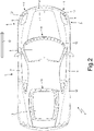
figure 2 is a top view of the car offigure 1 ; -
figure 3 is a side view of part of the car offigure 1 ; -
figure 4 is a view, on a larger scale, of a nozzle of a pneumatic windscreen wiper; and -
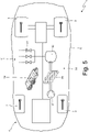
figure 5 is a schematic plan view of the car offigure 1 . - In
figure 1 , number 1 indicates, as a whole, a car with a rear (or central) engine comprising a chassis, which supports a pair offront wheels 2 and a pair ofrear wheels 3. - Between the
front wheels 2 and therear wheels 3 there is apassenger compartment 4, to which access is granted through a pair ofdoors 5; at the front thepassenger compartment 5 is delimited by awindscreen 6. In front of thepassenger compartment 4 there is a front compartment (for example, though not exclusively, for baggage), which is closed at the top by a front hinged hood 7. On the sides of the front hood 7 there are twoheadlamps 8, each closed at the front by atransparent glass 9. Behind thepassenger compartment 4 there is a rear engine compartment, which is closed at the top by a hinged rear hood 10 (shown infigure 2 ), which is transparent and the centre and is usually arranged in a substantially horizontal position. - According to
figure 2 , the car 1 comprises four pneumatic wipers 11: a firstpneumatic wiper 11 is coupled to thewindscreen 6 in order to clean thewindscreen 6, two secondpneumatic wipers 11 are coupled to thetransparent glasses 9 of the twoheadlamps 8 in order to clean thetransparent glasses 9 and a thirdpneumatic wiper 11 is coupled to therear hood 10 in order to clean therear hood 10. - Each
pneumatic wiper 11 comprises a plurality ofnozzles 12, which are arranged side by side and at a given distance from one another along an edge of the correspondingtransparent element nozzle 12 is oriented towards the correspondingtransparent element figure 3 ), which hits the correspondingtransparent element transparent element compressed air jet 13 emitted by eachnozzle 12 is oriented parallel to the correspondingtransparent element same wiper 11, thenozzles 12 could have a non-uniform distribution in the space (namely, mutual distance): for example, in the case of thewindscreen 6, thenozzles 12 could be closer to one another in the area of thewindscreen 6 in front of the driver and farther from one another in the area of thewindscreen 6 in front of the passenger. - The
compressed air jet 13 emitted by eachnozzle 12 preferably is a supersonic jet, namely the compressed air flowing out of thenozzle 12 has a moving speed that is greater than the speed of sound; in other words, eachnozzle 12 is shaped so as to emit thecompressed air jet 13 at a supersonic speed. - In each
pneumatic wiper 11, thenozzles 12 are preferably arranged in the area of a front edge of the correspondingtransparent element compressed air jets 13 emitted by thenozzles 12, thus increasing the effectiveness thereof. - According to a possible embodiment, at least some
nozzles 12 have an elongated shape (as shown infigure 4 ) having a greater transverse dimension, which is perpendicular to the travel direction D of the car 1, than a longitudinal dimension, which is parallel to the travel direction D of the car 1; this embodiment allows onesingle nozzle 12 to hit, with itscompressed air jet 13, a larger surface of the correspondingtransparent element nozzles 12 to be more widely spaced apart from one another (obviously, this solution mainly applies when the correspondingtransparent element - According to
figure 5 , eachpneumatic wiper 11 also comprises asource 14 of compressed air and (at least) acontrol valve 15, which is interposed between thenozzles 12 and thecompressed air source 14 and is designed to regulate the compressed air flow. - Generally speaking, each
pneumatic wiper 11 comprises onesingle control valve 15, which opens or closes the supply of compressed air to allnozzles 12, but, alternatively, there can beseveral valves 15 for a samepneumatic wiper 11, thus dividing thenozzles 12 into different areas controlled independently of one another (obviously, thus solution mainly applies when the correspondingtransparent element windscreen 6, the sole area of thewindscreen 6 in front of the driver could be kept clean (by not supplying compressed air to thenozzles 12 arranged in front of the passenger) when the passenger's seat is empty (the absence/presence of the passenger is a known item of information thanks to the sensors used to warn that the set belts are not fastened). - Generally speaking, each
control valve 15 is an ON/OFF valve and is adapted to only assume an open position or a closed position; this solution is preferable for it is simpler, more economic and more energetically efficient and it allows anyway for an action of thepneumatic wiper 11 divided into parts, modulating the timely duration and/or the frequency of the single openings of thecontrol valve 15. - According to the preferred embodiment shown in
figure 5 , thecompressed air source 14 is common to allpneumatic wipers 11, namely thepneumatic wipers 11 share the samecompressed air source 14, which is only one. - The (single) common compressed
air source 14 comprises acompressed air tank 16, which is connected to thecontrol valves 15, and acompressor 17, which supplies thecompressed air tank 16. - A
heat exchanger 18 is provided, which is interposed between thecompressor 17 and thecompressed air tank 16 and is adapted to cool down the compressed air supplied by thecompressor 17 to thecompressed air tank 16, thus reducing the volume occupied by the compressed air in thecompressed air tank 16; thanks to the cooling of the compressed air supplied by thecompressor 17 to thecompressed air tank 16, a greater quantity (mass) of compressed air can be stored in thecompressed air tank 16, the pressure being equal. - According to a preferred embodiment, the
compressor 17 directly receives the motion from an internal combustion engine of the car 1. Alternatively, thecompressor 17 receives the motion from a front axle (namely, from the two front wheels 2) or from a rear axle (namely, from the two rear wheels 3); in other words, a rotor of thecompressor 17 can be connected to the front axle (namely, to the two front wheels 2) or to the rear axle (namely, to the two rear wheels 3) in order to be operated by thefront wheels 2 or by the rear wheels 3 (thus, exploiting the motion of thefront wheels 2 or the motion of the rear wheels 3). - According to a preferred embodiments, a
control unit 19 activates thecompressor 17, using the motion received from thewheels internal combustion engine 4, (especially) during the braking phase so as to use the kinetic energy owned by the car 1, which otherwise would be dissipated in heat by the braking system. - According to other embodiments which are not shown herein, a
pneumatic wiper 11 is used to clean a transparent element covering an optical sensor (for example a camera) of the car 1, which is used for the autonomous driving mode, or a transparent element protecting turn signals or rear lamps. - In the embodiment shown in the accompanying figures, the
pneumatic wiper 11 is mounted on a car 1; according to other embodiments which are not shown herein, thepneumatic wiper 11 is mounted on a different type of road vehicle (for example, vans, trucks or buses) or also on a non-road vehicle (for example, streetcars, locomotives, aircraft, boats). - The embodiments described herein can be combined with one another, without for this reason going beyond the scope of protection of the invention defined by the appended claims.
- The
pneumatic wiper 11 described above has numerous advantages. - First of all, the
pneumatic wiper 11 described above is completely "invisible" (namely, hidden) both from an aerodynamic point of view (namely, it does not worsen aerodynamic efficiency) and from an aesthetic point of view. - Furthermore, the
pneumatic wiper 11 described above does not require any type of periodic maintenance and basically is "self-cleaning" (namely, is capable of eliminating possible deposits or dirt building up on it when the vehicle remains parked outdoor for a long time by itself). - The
pneumatic wiper 11 described above has, close to thetransparent element compressed air source 14 and thecontrol valve 15 can be placed away from the nozzles 12) and, hence, does not pose any significant limitation to the definition of the architecture of the car. - The
pneumatic wiper 11 described above completely remains within the dimensions of car body and, therefore, is not subjected to the risk of accidental damages, for example when the vehicle is washed in automated washing stations. - Finally, the
pneumatic wiper 11 described above, for it can share onesingle source 12 of compressed air with all the otherpneumatic wipers 11 installed in the same car 1, allows, with a moderate cost increase, all transparent elements of the car 1 to be cleaned. -
- 1
- car
- 2
- front wheels
- 3
- rear wheels
- 4
- passenger compartment
- 5
- doors
- 6
- windscreen
- 7
- front hood
- 8
- headlamps
- 9
- transparent glass
- 10
- rear hood
- 11
- pneumatic wipers
- 12
- nozzles
- 13
- compressed air jet
- 14
- compressed air source
- 15
- control valve
- 16
- tank
- 17
- compressor
- 18
- heat exchanger
- 19
- control unit
- D
- travel direction
Claims (10)
- A pneumatic windscreen wiper (11) for a transparent element (6; 9; 10) of a vehicle (1); the pneumatic windscreen wiper (11) comprises:at least one nozzle (12) which is arranged at an edge of the transparent element (6; 9; 10), is oriented towards the transparent element (6; 9; 10), and is capable of emitting a compressed air jet (13) that hits the transparent element (6; 9; 10) to lick the transparent element (6; 9; 10) ;a source (14) of compressed air comprising a compressed air tank (16) and a compressor (17) which is adapted to supply compressed air into the tank (16); anda control valve (15) which is interposed between the nozzle (12) and the source (14) of compressed air and is suitable for regulating the flow of compressed air;the pneumatic windscreen wiper (11) is characterized in that the source (14) of compressed air comprises a heat exchanger (18) which is interposed between the compressor (17) and the compressed air tank (16) and is suitable for cooling the compressed air which is supplied by the compressor (17) to the compressed air tank (16).
- The pneumatic windscreen wiper (11) according to claim 1, wherein the compressed air jet (13) emitted by the nozzle (12) is oriented parallel to the transparent element (6; 9; 10) .
- The pneumatic windscreen wiper (11) according to claim 1 or 2, wherein the nozzle (12) is shaped to emit the compressed air jet (13) at supersonic speed.
- The pneumatic windscreen wiper (11) according to claim 1, 2 or 3, wherein the nozzle (12) is arranged at a front edge of the transparent element (6; 9; 10) with respect to a travel direction (D) of the vehicle (1).
- The pneumatic windscreen wiper (11) according to any one of the claims from 1 to 4 and comprising a plurality of nozzles (12) which are arranged side by side and at a certain distance from each other along the edge of the transparent element (6; 9; 10).
- The pneumatic windscreen wiper (11) according to any one of the claims from 1 to 5, wherein the control valve (15) is of the ON/OFF type and is capable of assuming only an open position and a closed position.
- The pneumatic windscreen wiper (11) according to any one of the claims from 1 to 6, wherein the nozzle (12) has an elongated shape having a transverse dimension which is perpendicular to a travel direction (D) of the vehicle (1) greater than a longitudinal dimension which is parallel to the travel direction of the vehicle (1).
- A vehicle (1) comprising:a transparent element (6; 9; 10); anda pneumatic windscreen wiper (11) according to any one of the claims from 1 to 7.
- The vehicle (1) according to claim 8, wherein the compressor (17) receives the motion directly from an internal combustion engine of the vehicle (1).
- The vehicle (1) according to claim 8, wherein the compressor (17) receives motion from a front axle or from a rear axle of the vehicle (1).
Applications Claiming Priority (2)
| Application Number | Priority Date | Filing Date | Title |
|---|---|---|---|
| IT102020000011689A IT202000011689A1 (en) | 2020-05-20 | 2020-05-20 | PNEUMATIC WINDSCREEN WIPER FOR A TRANSPARENT ELEMENT OF A VEHICLE |
| PCT/IB2021/054382 WO2021234629A1 (en) | 2020-05-20 | 2021-05-20 | Pneumatic windscreen wiper for a transparent element of a vehicle |
Publications (2)
| Publication Number | Publication Date |
|---|---|
| EP3959109A1 EP3959109A1 (en) | 2022-03-02 |
| EP3959109B1 true EP3959109B1 (en) | 2022-11-30 |
Family
ID=71994908
Family Applications (1)
| Application Number | Title | Priority Date | Filing Date |
|---|---|---|---|
| EP21733538.9A Active EP3959109B1 (en) | 2020-05-20 | 2021-05-20 | Pneumatic windscreen wiper for a transparent element of a vehicle |
Country Status (6)
| Country | Link |
|---|---|
| US (1) | US12043222B2 (en) |
| EP (1) | EP3959109B1 (en) |
| JP (2) | JP2023525604A (en) |
| CN (1) | CN114222686B (en) |
| IT (1) | IT202000011689A1 (en) |
| WO (1) | WO2021234629A1 (en) |
Families Citing this family (1)
| Publication number | Priority date | Publication date | Assignee | Title |
|---|---|---|---|---|
| FR3157281A1 (en) * | 2023-12-22 | 2025-06-27 | Stellantis Auto Sas | Rear trunk assembly for motor vehicle |
Family Cites Families (20)
| Publication number | Priority date | Publication date | Assignee | Title |
|---|---|---|---|---|
| JPS50114975U (en) * | 1974-02-28 | 1975-09-19 | ||
| JPS524639U (en) * | 1975-06-25 | 1977-01-13 | ||
| JPS58102891A (en) * | 1981-12-11 | 1983-06-18 | 日産自動車株式会社 | Portable pneumatic tool device |
| JPS617459U (en) * | 1984-06-20 | 1986-01-17 | 株式会社 上田フアスナ−エンジニアリング | car pneumatic wiper |
| JPH0645878U (en) * | 1992-11-03 | 1994-06-21 | 正 塩川 | All-weather air wiper |
| JP3492726B2 (en) * | 1993-08-23 | 2004-02-03 | 株式会社イー・シー・エス | Air wiper and water repellent liquid coating equipment |
| JPH10323529A (en) * | 1997-05-26 | 1998-12-08 | Nissan Diesel Motor Co Ltd | Compressed air dryer |
| JP3646052B2 (en) * | 2000-09-19 | 2005-05-11 | 望月 義嗣 | Hot air type air wiper device using thermal energy of exhaust gas or engine cooling water |
| JP4057292B2 (en) * | 2001-12-20 | 2008-03-05 | 澁谷工業株式会社 | Injection nozzle |
| DE10357762A1 (en) * | 2003-07-28 | 2005-02-24 | Wabco Gmbh & Co.Ohg | Electronic compressed air system |
| KR100792790B1 (en) * | 2006-08-21 | 2008-01-10 | 한국기계연구원 | Compressed air storage power generation system and power generation method using the same |
| KR20070097388A (en) * | 2007-08-23 | 2007-10-04 | 김우열 | Automotive Air Jet Wiper |
| WO2009060413A2 (en) * | 2007-11-09 | 2009-05-14 | Fioravanti S.R.L. | An automobile vehicle with a wiperless cleaning system for glazed surfaces and the like |
| FR2938634B1 (en) * | 2008-09-05 | 2012-12-07 | Valeo Systemes Dessuyage | DEVICE FOR HEATING LIQUID WITH TWO FLOW ROUTES FOR MOTOR VEHICLE. |
| US9840129B2 (en) * | 2011-09-29 | 2017-12-12 | Subaru Corporation | Vehicle, cooling apparatus, and cooling method |
| US10471937B2 (en) * | 2012-10-31 | 2019-11-12 | Kenneth Davis | Compressed air vehicle screen clearing system |
| CN203518374U (en) * | 2013-09-30 | 2014-04-02 | 苏州新同创汽车空调有限公司 | Automatic defrosting device |
| CN104174261A (en) * | 2014-08-19 | 2014-12-03 | 东南大学 | Compressed air drying device based on vortex tube refrigeration technology and working method of compressed air drying device |
| WO2016177380A1 (en) * | 2015-05-07 | 2016-11-10 | Nyenstad Mønster Dan | Wiperless cleaning system for transparent surfaces using air jets |
| CN105196975B (en) * | 2015-10-23 | 2017-07-11 | 北汽福田汽车股份有限公司 | Front windshield deicing system and the vehicle with it |
-
2020
- 2020-05-20 IT IT102020000011689A patent/IT202000011689A1/en unknown
-
2021
- 2021-05-20 CN CN202180003707.6A patent/CN114222686B/en active Active
- 2021-05-20 US US17/614,588 patent/US12043222B2/en active Active
- 2021-05-20 JP JP2021570166A patent/JP2023525604A/en active Pending
- 2021-05-20 WO PCT/IB2021/054382 patent/WO2021234629A1/en not_active Ceased
- 2021-05-20 EP EP21733538.9A patent/EP3959109B1/en active Active
-
2025
- 2025-06-11 JP JP2025001910U patent/JP3252340U/en active Active
Also Published As
| Publication number | Publication date |
|---|---|
| JP2023525604A (en) | 2023-06-19 |
| JP3252340U (en) | 2025-08-07 |
| CN114222686B (en) | 2025-06-27 |
| EP3959109A1 (en) | 2022-03-02 |
| CN114222686A (en) | 2022-03-22 |
| WO2021234629A1 (en) | 2021-11-25 |
| IT202000011689A1 (en) | 2021-11-20 |
| US20230064128A1 (en) | 2023-03-02 |
| US12043222B2 (en) | 2024-07-23 |
Similar Documents
| Publication | Publication Date | Title |
|---|---|---|
| US6290361B1 (en) | Universal clearing air system for windows and external mirrors of a vehicle | |
| US7686383B2 (en) | Retractable curved air dam | |
| JP3252340U (en) | Pneumatic windscreen wiper for transparent elements of a vehicle | |
| CN102398649B (en) | Motorcycle front fairing | |
| US20030155001A1 (en) | Device for keeping clean optical elements on motor vehicle clean, in particular covers for sensors or cameras | |
| EP2511134A1 (en) | Vehicle Light Unit | |
| WO2016062382A1 (en) | Grille for a vehicle, in particular a commercial vehicle as well as a vehicle | |
| US11976946B2 (en) | Sensor housing with deflector | |
| CN107531143B (en) | Commercial vehicles including superstructure and chassis | |
| US6798163B2 (en) | Wiper system for motor vehicles | |
| US10131211B1 (en) | Windshield contaminant reducing assembly and method | |
| US8973208B2 (en) | Rear wiper system | |
| US12372621B2 (en) | Sensor protection device and control system thereof | |
| CN215663189U (en) | Rearview mirror and automobile | |
| US20230373443A1 (en) | Roof assembly comprising a cleaning feature and motor vehicle comprising a cleaning feature | |
| CN113734086B (en) | Automobile movable grille system and automobile | |
| GB2360444A (en) | Mirror clearing means | |
| US10793115B2 (en) | Vehicle rear wiper system | |
| US20240151833A1 (en) | Sensor assembly with duct | |
| US20260070518A1 (en) | Passive exterior camera cleaning system utilizing pressurized air | |
| CN201472284U (en) | Protection system used for preventing automobiles from crashing flying insects | |
| US20250321417A1 (en) | Cleaning system, optical sensor assembly comprising such a cleaning system and vehicle comprising such an assembly | |
| KR100633424B1 (en) | Car side mirror for raindrop removal | |
| CN111703398B (en) | A hood air guide device that prevents foreign matter impact and can defog and defrost | |
| JPH06156204A (en) | Air wiper for vehicle |
Legal Events
| Date | Code | Title | Description |
|---|---|---|---|
| STAA | Information on the status of an ep patent application or granted ep patent |
Free format text: STATUS: UNKNOWN |
|
| STAA | Information on the status of an ep patent application or granted ep patent |
Free format text: STATUS: THE INTERNATIONAL PUBLICATION HAS BEEN MADE |
|
| PUAI | Public reference made under article 153(3) epc to a published international application that has entered the european phase |
Free format text: ORIGINAL CODE: 0009012 |
|
| STAA | Information on the status of an ep patent application or granted ep patent |
Free format text: STATUS: REQUEST FOR EXAMINATION WAS MADE |
|
| 17P | Request for examination filed |
Effective date: 20211126 |
|
| AK | Designated contracting states |
Kind code of ref document: A1 Designated state(s): AL AT BE BG CH CY CZ DE DK EE ES FI FR GB GR HR HU IE IS IT LI LT LU LV MC MK MT NL NO PL PT RO RS SE SI SK SM TR |
|
| GRAP | Despatch of communication of intention to grant a patent |
Free format text: ORIGINAL CODE: EPIDOSNIGR1 |
|
| STAA | Information on the status of an ep patent application or granted ep patent |
Free format text: STATUS: GRANT OF PATENT IS INTENDED |
|
| INTG | Intention to grant announced |
Effective date: 20220617 |
|
| GRAS | Grant fee paid |
Free format text: ORIGINAL CODE: EPIDOSNIGR3 |
|
| GRAA | (expected) grant |
Free format text: ORIGINAL CODE: 0009210 |
|
| STAA | Information on the status of an ep patent application or granted ep patent |
Free format text: STATUS: THE PATENT HAS BEEN GRANTED |
|
| DAV | Request for validation of the european patent (deleted) | ||
| DAX | Request for extension of the european patent (deleted) | ||
| AK | Designated contracting states |
Kind code of ref document: B1 Designated state(s): AL AT BE BG CH CY CZ DE DK EE ES FI FR GB GR HR HU IE IS IT LI LT LU LV MC MK MT NL NO PL PT RO RS SE SI SK SM TR |
|
| REG | Reference to a national code |
Ref country code: CH Ref legal event code: EP Ref country code: GB Ref legal event code: FG4D |
|
| REG | Reference to a national code |
Ref country code: AT Ref legal event code: REF Ref document number: 1534449 Country of ref document: AT Kind code of ref document: T Effective date: 20221215 |
|
| REG | Reference to a national code |
Ref country code: IE Ref legal event code: FG4D |
|
| REG | Reference to a national code |
Ref country code: DE Ref legal event code: R096 Ref document number: 602021000891 Country of ref document: DE |
|
| REG | Reference to a national code |
Ref country code: LT Ref legal event code: MG9D |
|
| REG | Reference to a national code |
Ref country code: NL Ref legal event code: MP Effective date: 20221130 |
|
| PG25 | Lapsed in a contracting state [announced via postgrant information from national office to epo] |
Ref country code: SE Free format text: LAPSE BECAUSE OF FAILURE TO SUBMIT A TRANSLATION OF THE DESCRIPTION OR TO PAY THE FEE WITHIN THE PRESCRIBED TIME-LIMIT Effective date: 20221130 Ref country code: PT Free format text: LAPSE BECAUSE OF FAILURE TO SUBMIT A TRANSLATION OF THE DESCRIPTION OR TO PAY THE FEE WITHIN THE PRESCRIBED TIME-LIMIT Effective date: 20230331 Ref country code: NO Free format text: LAPSE BECAUSE OF FAILURE TO SUBMIT A TRANSLATION OF THE DESCRIPTION OR TO PAY THE FEE WITHIN THE PRESCRIBED TIME-LIMIT Effective date: 20230228 Ref country code: LT Free format text: LAPSE BECAUSE OF FAILURE TO SUBMIT A TRANSLATION OF THE DESCRIPTION OR TO PAY THE FEE WITHIN THE PRESCRIBED TIME-LIMIT Effective date: 20221130 Ref country code: FI Free format text: LAPSE BECAUSE OF FAILURE TO SUBMIT A TRANSLATION OF THE DESCRIPTION OR TO PAY THE FEE WITHIN THE PRESCRIBED TIME-LIMIT Effective date: 20221130 Ref country code: ES Free format text: LAPSE BECAUSE OF FAILURE TO SUBMIT A TRANSLATION OF THE DESCRIPTION OR TO PAY THE FEE WITHIN THE PRESCRIBED TIME-LIMIT Effective date: 20221130 |
|
| REG | Reference to a national code |
Ref country code: AT Ref legal event code: MK05 Ref document number: 1534449 Country of ref document: AT Kind code of ref document: T Effective date: 20221130 |
|
| PG25 | Lapsed in a contracting state [announced via postgrant information from national office to epo] |
Ref country code: RS Free format text: LAPSE BECAUSE OF FAILURE TO SUBMIT A TRANSLATION OF THE DESCRIPTION OR TO PAY THE FEE WITHIN THE PRESCRIBED TIME-LIMIT Effective date: 20221130 Ref country code: PL Free format text: LAPSE BECAUSE OF FAILURE TO SUBMIT A TRANSLATION OF THE DESCRIPTION OR TO PAY THE FEE WITHIN THE PRESCRIBED TIME-LIMIT Effective date: 20221130 Ref country code: LV Free format text: LAPSE BECAUSE OF FAILURE TO SUBMIT A TRANSLATION OF THE DESCRIPTION OR TO PAY THE FEE WITHIN THE PRESCRIBED TIME-LIMIT Effective date: 20221130 Ref country code: IS Free format text: LAPSE BECAUSE OF FAILURE TO SUBMIT A TRANSLATION OF THE DESCRIPTION OR TO PAY THE FEE WITHIN THE PRESCRIBED TIME-LIMIT Effective date: 20230330 Ref country code: HR Free format text: LAPSE BECAUSE OF FAILURE TO SUBMIT A TRANSLATION OF THE DESCRIPTION OR TO PAY THE FEE WITHIN THE PRESCRIBED TIME-LIMIT Effective date: 20221130 Ref country code: GR Free format text: LAPSE BECAUSE OF FAILURE TO SUBMIT A TRANSLATION OF THE DESCRIPTION OR TO PAY THE FEE WITHIN THE PRESCRIBED TIME-LIMIT Effective date: 20230301 |
|
| PG25 | Lapsed in a contracting state [announced via postgrant information from national office to epo] |
Ref country code: NL Free format text: LAPSE BECAUSE OF FAILURE TO SUBMIT A TRANSLATION OF THE DESCRIPTION OR TO PAY THE FEE WITHIN THE PRESCRIBED TIME-LIMIT Effective date: 20221130 |
|
| P01 | Opt-out of the competence of the unified patent court (upc) registered |
Effective date: 20230525 |
|
| PG25 | Lapsed in a contracting state [announced via postgrant information from national office to epo] |
Ref country code: SM Free format text: LAPSE BECAUSE OF FAILURE TO SUBMIT A TRANSLATION OF THE DESCRIPTION OR TO PAY THE FEE WITHIN THE PRESCRIBED TIME-LIMIT Effective date: 20221130 Ref country code: RO Free format text: LAPSE BECAUSE OF FAILURE TO SUBMIT A TRANSLATION OF THE DESCRIPTION OR TO PAY THE FEE WITHIN THE PRESCRIBED TIME-LIMIT Effective date: 20221130 Ref country code: EE Free format text: LAPSE BECAUSE OF FAILURE TO SUBMIT A TRANSLATION OF THE DESCRIPTION OR TO PAY THE FEE WITHIN THE PRESCRIBED TIME-LIMIT Effective date: 20221130 Ref country code: DK Free format text: LAPSE BECAUSE OF FAILURE TO SUBMIT A TRANSLATION OF THE DESCRIPTION OR TO PAY THE FEE WITHIN THE PRESCRIBED TIME-LIMIT Effective date: 20221130 Ref country code: CZ Free format text: LAPSE BECAUSE OF FAILURE TO SUBMIT A TRANSLATION OF THE DESCRIPTION OR TO PAY THE FEE WITHIN THE PRESCRIBED TIME-LIMIT Effective date: 20221130 Ref country code: AT Free format text: LAPSE BECAUSE OF FAILURE TO SUBMIT A TRANSLATION OF THE DESCRIPTION OR TO PAY THE FEE WITHIN THE PRESCRIBED TIME-LIMIT Effective date: 20221130 |
|
| PG25 | Lapsed in a contracting state [announced via postgrant information from national office to epo] |
Ref country code: SK Free format text: LAPSE BECAUSE OF FAILURE TO SUBMIT A TRANSLATION OF THE DESCRIPTION OR TO PAY THE FEE WITHIN THE PRESCRIBED TIME-LIMIT Effective date: 20221130 Ref country code: AL Free format text: LAPSE BECAUSE OF FAILURE TO SUBMIT A TRANSLATION OF THE DESCRIPTION OR TO PAY THE FEE WITHIN THE PRESCRIBED TIME-LIMIT Effective date: 20221130 |
|
| REG | Reference to a national code |
Ref country code: DE Ref legal event code: R097 Ref document number: 602021000891 Country of ref document: DE |
|
| PLBE | No opposition filed within time limit |
Free format text: ORIGINAL CODE: 0009261 |
|
| STAA | Information on the status of an ep patent application or granted ep patent |
Free format text: STATUS: NO OPPOSITION FILED WITHIN TIME LIMIT |
|
| 26N | No opposition filed |
Effective date: 20230831 |
|
| PG25 | Lapsed in a contracting state [announced via postgrant information from national office to epo] |
Ref country code: SI Free format text: LAPSE BECAUSE OF FAILURE TO SUBMIT A TRANSLATION OF THE DESCRIPTION OR TO PAY THE FEE WITHIN THE PRESCRIBED TIME-LIMIT Effective date: 20221130 |
|
| PG25 | Lapsed in a contracting state [announced via postgrant information from national office to epo] |
Ref country code: MC Free format text: LAPSE BECAUSE OF FAILURE TO SUBMIT A TRANSLATION OF THE DESCRIPTION OR TO PAY THE FEE WITHIN THE PRESCRIBED TIME-LIMIT Effective date: 20221130 |
|
| REG | Reference to a national code |
Ref country code: BE Ref legal event code: MM Effective date: 20230531 |
|
| PG25 | Lapsed in a contracting state [announced via postgrant information from national office to epo] |
Ref country code: MC Free format text: LAPSE BECAUSE OF FAILURE TO SUBMIT A TRANSLATION OF THE DESCRIPTION OR TO PAY THE FEE WITHIN THE PRESCRIBED TIME-LIMIT Effective date: 20221130 Ref country code: LU Free format text: LAPSE BECAUSE OF NON-PAYMENT OF DUE FEES Effective date: 20230520 |
|
| REG | Reference to a national code |
Ref country code: IE Ref legal event code: MM4A |
|
| PG25 | Lapsed in a contracting state [announced via postgrant information from national office to epo] |
Ref country code: IE Free format text: LAPSE BECAUSE OF NON-PAYMENT OF DUE FEES Effective date: 20230520 |
|
| PG25 | Lapsed in a contracting state [announced via postgrant information from national office to epo] |
Ref country code: IE Free format text: LAPSE BECAUSE OF NON-PAYMENT OF DUE FEES Effective date: 20230520 |
|
| PG25 | Lapsed in a contracting state [announced via postgrant information from national office to epo] |
Ref country code: BE Free format text: LAPSE BECAUSE OF NON-PAYMENT OF DUE FEES Effective date: 20230531 |
|
| PG25 | Lapsed in a contracting state [announced via postgrant information from national office to epo] |
Ref country code: BG Free format text: LAPSE BECAUSE OF FAILURE TO SUBMIT A TRANSLATION OF THE DESCRIPTION OR TO PAY THE FEE WITHIN THE PRESCRIBED TIME-LIMIT Effective date: 20221130 |
|
| PG25 | Lapsed in a contracting state [announced via postgrant information from national office to epo] |
Ref country code: BG Free format text: LAPSE BECAUSE OF FAILURE TO SUBMIT A TRANSLATION OF THE DESCRIPTION OR TO PAY THE FEE WITHIN THE PRESCRIBED TIME-LIMIT Effective date: 20221130 |
|
| REG | Reference to a national code |
Ref country code: CH Ref legal event code: PL |
|
| PG25 | Lapsed in a contracting state [announced via postgrant information from national office to epo] |
Ref country code: CH Free format text: LAPSE BECAUSE OF NON-PAYMENT OF DUE FEES Effective date: 20240531 |
|
| PGFP | Annual fee paid to national office [announced via postgrant information from national office to epo] |
Ref country code: DE Payment date: 20250528 Year of fee payment: 5 |
|
| PGFP | Annual fee paid to national office [announced via postgrant information from national office to epo] |
Ref country code: IT Payment date: 20250509 Year of fee payment: 5 |
|
| PGFP | Annual fee paid to national office [announced via postgrant information from national office to epo] |
Ref country code: FR Payment date: 20250526 Year of fee payment: 5 |
|
| PG25 | Lapsed in a contracting state [announced via postgrant information from national office to epo] |
Ref country code: CY Free format text: LAPSE BECAUSE OF FAILURE TO SUBMIT A TRANSLATION OF THE DESCRIPTION OR TO PAY THE FEE WITHIN THE PRESCRIBED TIME-LIMIT; INVALID AB INITIO Effective date: 20210520 |
|
| PG25 | Lapsed in a contracting state [announced via postgrant information from national office to epo] |
Ref country code: HU Free format text: LAPSE BECAUSE OF FAILURE TO SUBMIT A TRANSLATION OF THE DESCRIPTION OR TO PAY THE FEE WITHIN THE PRESCRIBED TIME-LIMIT; INVALID AB INITIO Effective date: 20210520 |
|
| PG25 | Lapsed in a contracting state [announced via postgrant information from national office to epo] |
Ref country code: TR Free format text: LAPSE BECAUSE OF FAILURE TO SUBMIT A TRANSLATION OF THE DESCRIPTION OR TO PAY THE FEE WITHIN THE PRESCRIBED TIME-LIMIT Effective date: 20221130 |
|
| PGFP | Annual fee paid to national office [announced via postgrant information from national office to epo] |
Ref country code: GB Payment date: 20260304 Year of fee payment: 6 |