EP3959088B1 - Adjustable spring seat - Google Patents
Adjustable spring seat Download PDFInfo
- Publication number
- EP3959088B1 EP3959088B1 EP20742817.8A EP20742817A EP3959088B1 EP 3959088 B1 EP3959088 B1 EP 3959088B1 EP 20742817 A EP20742817 A EP 20742817A EP 3959088 B1 EP3959088 B1 EP 3959088B1
- Authority
- EP
- European Patent Office
- Prior art keywords
- adjustable
- spring seat
- flange
- thread
- seat according
- Prior art date
- Legal status (The legal status is an assumption and is not a legal conclusion. Google has not performed a legal analysis and makes no representation as to the accuracy of the status listed.)
- Active
Links
- 230000035939 shock Effects 0.000 claims description 18
- 239000006096 absorbing agent Substances 0.000 claims description 16
- 230000000295 complement effect Effects 0.000 claims description 3
- 238000000926 separation method Methods 0.000 claims description 3
- 230000000694 effects Effects 0.000 claims description 2
- 230000000452 restraining effect Effects 0.000 claims description 2
- 239000000725 suspension Substances 0.000 description 10
- 238000004804 winding Methods 0.000 description 4
- 230000036316 preload Effects 0.000 description 3
- 230000006835 compression Effects 0.000 description 2
- 238000007906 compression Methods 0.000 description 2
- 239000012530 fluid Substances 0.000 description 2
- 230000001419 dependent effect Effects 0.000 description 1
- 230000007246 mechanism Effects 0.000 description 1
- 238000004806 packaging method and process Methods 0.000 description 1
- 230000004043 responsiveness Effects 0.000 description 1
Images


Classifications
-
- F—MECHANICAL ENGINEERING; LIGHTING; HEATING; WEAPONS; BLASTING
- F16—ENGINEERING ELEMENTS AND UNITS; GENERAL MEASURES FOR PRODUCING AND MAINTAINING EFFECTIVE FUNCTIONING OF MACHINES OR INSTALLATIONS; THERMAL INSULATION IN GENERAL
- F16F—SPRINGS; SHOCK-ABSORBERS; MEANS FOR DAMPING VIBRATION
- F16F1/00—Springs
- F16F1/02—Springs made of steel or other material having low internal friction; Wound, torsion, leaf, cup, ring or the like springs, the material of the spring not being relevant
- F16F1/04—Wound springs
- F16F1/12—Attachments or mountings
- F16F1/121—Attachments or mountings adjustable, e.g. to modify spring characteristics
-
- B—PERFORMING OPERATIONS; TRANSPORTING
- B60—VEHICLES IN GENERAL
- B60G—VEHICLE SUSPENSION ARRANGEMENTS
- B60G11/00—Resilient suspensions characterised by arrangement, location or kind of springs
- B60G11/14—Resilient suspensions characterised by arrangement, location or kind of springs having helical, spiral or coil springs only
-
- B—PERFORMING OPERATIONS; TRANSPORTING
- B60—VEHICLES IN GENERAL
- B60G—VEHICLE SUSPENSION ARRANGEMENTS
- B60G15/00—Resilient suspensions characterised by arrangement, location or type of combined spring and vibration damper, e.g. telescopic type
- B60G15/02—Resilient suspensions characterised by arrangement, location or type of combined spring and vibration damper, e.g. telescopic type having mechanical spring
- B60G15/06—Resilient suspensions characterised by arrangement, location or type of combined spring and vibration damper, e.g. telescopic type having mechanical spring and fluid damper
- B60G15/062—Resilient suspensions characterised by arrangement, location or type of combined spring and vibration damper, e.g. telescopic type having mechanical spring and fluid damper the spring being arranged around the damper
- B60G15/065—Resilient suspensions characterised by arrangement, location or type of combined spring and vibration damper, e.g. telescopic type having mechanical spring and fluid damper the spring being arranged around the damper characterised by the use of a combination of springs
-
- B—PERFORMING OPERATIONS; TRANSPORTING
- B60—VEHICLES IN GENERAL
- B60G—VEHICLE SUSPENSION ARRANGEMENTS
- B60G17/00—Resilient suspensions having means for adjusting the spring or vibration-damper characteristics, for regulating the distance between a supporting surface and a sprung part of vehicle or for locking suspension during use to meet varying vehicular or surface conditions, e.g. due to speed or load
- B60G17/02—Spring characteristics, e.g. mechanical springs and mechanical adjusting means
- B60G17/021—Spring characteristics, e.g. mechanical springs and mechanical adjusting means the mechanical spring being a coil spring
-
- F—MECHANICAL ENGINEERING; LIGHTING; HEATING; WEAPONS; BLASTING
- F16—ENGINEERING ELEMENTS AND UNITS; GENERAL MEASURES FOR PRODUCING AND MAINTAINING EFFECTIVE FUNCTIONING OF MACHINES OR INSTALLATIONS; THERMAL INSULATION IN GENERAL
- F16F—SPRINGS; SHOCK-ABSORBERS; MEANS FOR DAMPING VIBRATION
- F16F1/00—Springs
- F16F1/02—Springs made of steel or other material having low internal friction; Wound, torsion, leaf, cup, ring or the like springs, the material of the spring not being relevant
- F16F1/04—Wound springs
- F16F1/041—Wound springs with means for modifying the spring characteristics
-
- B—PERFORMING OPERATIONS; TRANSPORTING
- B60—VEHICLES IN GENERAL
- B60G—VEHICLE SUSPENSION ARRANGEMENTS
- B60G15/00—Resilient suspensions characterised by arrangement, location or type of combined spring and vibration damper, e.g. telescopic type
- B60G15/02—Resilient suspensions characterised by arrangement, location or type of combined spring and vibration damper, e.g. telescopic type having mechanical spring
- B60G15/06—Resilient suspensions characterised by arrangement, location or type of combined spring and vibration damper, e.g. telescopic type having mechanical spring and fluid damper
- B60G15/062—Resilient suspensions characterised by arrangement, location or type of combined spring and vibration damper, e.g. telescopic type having mechanical spring and fluid damper the spring being arranged around the damper
-
- B—PERFORMING OPERATIONS; TRANSPORTING
- B60—VEHICLES IN GENERAL
- B60G—VEHICLE SUSPENSION ARRANGEMENTS
- B60G2202/00—Indexing codes relating to the type of spring, damper or actuator
- B60G2202/10—Type of spring
- B60G2202/12—Wound spring
-
- B—PERFORMING OPERATIONS; TRANSPORTING
- B60—VEHICLES IN GENERAL
- B60G—VEHICLE SUSPENSION ARRANGEMENTS
- B60G2202/00—Indexing codes relating to the type of spring, damper or actuator
- B60G2202/30—Spring/Damper and/or actuator Units
- B60G2202/31—Spring/Damper and/or actuator Units with the spring arranged around the damper, e.g. MacPherson strut
- B60G2202/312—The spring being a wound spring
-
- B—PERFORMING OPERATIONS; TRANSPORTING
- B60—VEHICLES IN GENERAL
- B60G—VEHICLE SUSPENSION ARRANGEMENTS
- B60G2204/00—Indexing codes related to suspensions per se or to auxiliary parts
- B60G2204/10—Mounting of suspension elements
- B60G2204/12—Mounting of springs or dampers
- B60G2204/124—Mounting of coil springs
-
- B—PERFORMING OPERATIONS; TRANSPORTING
- B60—VEHICLES IN GENERAL
- B60G—VEHICLE SUSPENSION ARRANGEMENTS
- B60G2204/00—Indexing codes related to suspensions per se or to auxiliary parts
- B60G2204/40—Auxiliary suspension parts; Adjustment of suspensions
- B60G2204/46—Means for locking the suspension
- B60G2204/4604—Means for locking the suspension mechanically, e.g. using a hook as anticreep mechanism
-
- B—PERFORMING OPERATIONS; TRANSPORTING
- B60—VEHICLES IN GENERAL
- B60G—VEHICLE SUSPENSION ARRANGEMENTS
- B60G2204/00—Indexing codes related to suspensions per se or to auxiliary parts
- B60G2204/61—Adjustable during maintenance
-
- B—PERFORMING OPERATIONS; TRANSPORTING
- B60—VEHICLES IN GENERAL
- B60G—VEHICLE SUSPENSION ARRANGEMENTS
- B60G2206/00—Indexing codes related to the manufacturing of suspensions: constructional features, the materials used, procedures or tools
- B60G2206/01—Constructional features of suspension elements, e.g. arms, dampers, springs
- B60G2206/90—Maintenance
- B60G2206/93—Tools used for adjustments
-
- B—PERFORMING OPERATIONS; TRANSPORTING
- B60—VEHICLES IN GENERAL
- B60G—VEHICLE SUSPENSION ARRANGEMENTS
- B60G2500/00—Indexing codes relating to the regulated action or device
- B60G2500/20—Spring action or springs
-
- B—PERFORMING OPERATIONS; TRANSPORTING
- B60—VEHICLES IN GENERAL
- B60G—VEHICLE SUSPENSION ARRANGEMENTS
- B60G2500/00—Indexing codes relating to the regulated action or device
- B60G2500/30—Height or ground clearance
-
- B—PERFORMING OPERATIONS; TRANSPORTING
- B60—VEHICLES IN GENERAL
- B60G—VEHICLE SUSPENSION ARRANGEMENTS
- B60G2600/00—Indexing codes relating to particular elements, systems or processes used on suspension systems or suspension control systems
- B60G2600/20—Manual control or setting means
-
- B—PERFORMING OPERATIONS; TRANSPORTING
- B60—VEHICLES IN GENERAL
- B60G—VEHICLE SUSPENSION ARRANGEMENTS
- B60G2800/00—Indexing codes relating to the type of movement or to the condition of the vehicle and to the end result to be achieved by the control action
- B60G2800/16—Running
- B60G2800/162—Reducing road induced vibrations
Definitions
- the present invention relates to improvements in sprung shock absorbers and more particularly to adjustment mechanisms for enabling adjusting the spring loading of such sprung shock absorbers.
- shock absorbers such as are used on car suspension systems are well known in the art.
- Typical such shock absorbers comprise at least one spiral spring which winds around a central fluid filled shock damper strut.
- the strut is formed by a strut housing in which is longitudinally moveable a strut shaft so as to be extendable from and retractable into the strut housing.
- the strut housing is fluid filled and the end of the strut shaft acts like a piston in said housing so that its longitudinal movement is dampened.
- a pair of spaced apart spring seats are provided on the strut, one carried on the housing and one carried on the shaft, such that as the shaft moves into and out of the housing, the spring seats move towards and away from each other, causing the spring engaged between the two spring seats to be compressed or relaxed so as to control the shock absorbing capability of the shock absorber.
- This capability is, therefore, dependent on the spring constant of the spiral spring.
- a spring may be used without a strut, the spring seats being fixed, respectively to the body of the vehicle and to part of the wheel mount such as a wishbone so that the spring extends therebetween.
- the spring seat is formed by a tubular shaft having a second flange formed on one end thereof in fixed relation to the shaft, and a thread formed on the outer surface of the shaft extending from the other end on which is threadingly mounted a second, annular flange having a threaded inner surface.
- the second flange is longitudinally adjustable along the shaft by screwing the second flange up and down the thread.
- the second flange forms a spring seat for an end of a suspension spring, adjustment of the second flange along the shaft varying the separation between the first and second flanges so as to vary the preload on the spring.
- EP 2236324 which is considered to represent the closest prior art, discloses a shock absorber adjuster assembly having upper and lower adjustable flanges which can be extended and retracted through operation of the actuating motor, the upper and lower plates 4, 5 being secured against rotation relative to one another by means of an anti-rotation device.
- an adjustable spring seat for a shock absorber according to claim 1.
- a shock absorber adjuster assembly in accordance with the invention has the advantage that, by providing the adjuster with two adjustable flanges - one via an internal thread and one via an external thread, the adjustment range for the adjuster is effectively doubled compared to prior art adjusters of a corresponding size.
- the first flange acts as a spring seat, engaging an end of a suspension spring with the end of body which is opposite to the end in which the shaft of the second adjustable member and which extends beyond the first flange extending inside the windings of the abutting spring end to locate the spring end on the adjuster.
- shock absorber adjuster assembly according to claim 12.
- the body includes engaging means by means of which a torsional force can be applied to the body either to rotate it to effect simultaneous adjustment of both the first and the second adjustable members, or in order to hold it against rotation during adjustment of the first and/or second adjustable members.
- the body may include radial openings in its outer surface, preferably distributed at least partially around the circumference of the body into which are engageable teeth provided on a restraining tool so as to apply a torque to the body.
- a set of radial openings may be provided at more than one position along the length of the body so as to enable the tool to engage a set of openings even if one set is obscured by the first adjustable member.
- the radial openings are formed in a third flange which is provided on the outer surface of the body and is rotationally fast therewith, in particular is integrally formed with the body.
- the third flange also forms a stop for the travel of the first flange along the outer surface of the body towards the second flange.
- the openings may advantageously be formed as circumferentially extending slots.
- the engaging means may, however, take other forms such as flats, either directly on the other surface of the body or on a flange or the like rotationally fast therewith, which may be engaged by jaws of a spanner-type tool.
- the first and second threads may advantageously be of opposite hand such that the first and second flanges may be simultaneously moved away from each other by rotating the body in a one direction, and moved towards each other by rotating the body in the other direction.
- Stop means may be associated with each adjustable member to enable it to be locked in position against unintentional longitudinal movement.
- the stop means may take the form, for example, of a lock ring or nut which winds up behind each adjustable member, a locking collar, locking pins or the like.
- the outer dimension of the body is preferably sized to be a close tolerance fit inside the spring with which the spring seat engages to minimise lateral movement of the spring on the seat.
- Each of the main body and the second adjustable member are preferably tubular to allow a suspension strut to pass therethrough.
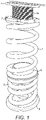
- FIG. 1 there is shown an example of applicant's own earlier prior art arrangement.
- a pair of springs 2, 3 are arrange in series between a pair of spring seats 4, 5, the upper spring seat 4 of which is adjustable.
- the upper spring seat 4 is formed by an upper flange 6 having a shaft 4b extending therefrom into the windings of the abutting end 2a of the spring 2 so as to retain it in position.
- the upper flange in use, engages against a part of the vehicle suspension to transmit the force from the suspension strut and spring to the vehicle.
- the outer surface 4a of the shaft 4b of the upper spring seat 4 is threaded and has a flange member 7 against which the upper end 2a of the spring 2 engages.
- the flange member 7 is threadably mounted on the outer surface 4a of the shaft so as to be longitudinally moveable along the shaft 4b by winding along the thread. In this way, the compression of the spring can be adjusted.
- the spring seat is formed a main body 14 having a shaft 14b which, in use, extends into the windings of the abutting end of the spring so as to retain the spring in position on the shaft.
- the shaft 14b of the main body 14 has a radial flange 14c formed on one end thereof and outer surface 14a of the shaft 14b, extending away from the radial flange, has a male thread 15a provided thereon on which is carried a first adjustable member in the form of an adjustable flange member 17.
- the adjustable flange member 17 is annular shaped and has a female thread 18 provided on its inner cylindrical surface 17a which is complementary to the thread 15a formed on the outer surface 14a of the shaft
- the flange member 17 is thereby threadably mounted on the outer surface 14a of the shaft 14b so as to be longitudinally moveable along the shaft 14b between a fully retracted position in which it engages against the radial flange 14c of the main body 14 and a fully extended position in which it is wound to the bottom of the thread 15a as shown in Figure 2 .
- the main body 14 furthermore has a female thread 15b formed on its inner cylindrical surface extending from the end on which the radial flange 14c is carried.
- a second adjustable member 19 shown in figures 5a and 5b , comprises a flange 19b with a shaft 19a extending therefrom having a male thread 19c formed on its outer cylindrical surface which is complementary to the female thread 15b formed on the inner cylindrical surface of the main body 14 such that the shaft 19a of the second adjustable member 19 is screwingly engageable into the main body 14 in order to secure it thereto, the separation between the flange 19b of the second adjustable member 19 and the radial flange 14c of the main body 14 being adjustable by screwing the second adjustable member 19 into and out of the main body 14.
- the main body 14 includes circumferentially extending slots 20 in the outer circumferential face of the radial flange 14c, as shown in Figures 2 and 6 , the slots 20 being distributed around the circumference of the flange 14c.
- An adjusting tool 21 includes teeth 22 thereon which are engageable in the slots 20 in order to enable a torsional load to be applied through the tool 21 to the main body 14.
- the adjustable spring seat is assembled with the first adjustable member 17 wound fully onto the thread 15a on the outer surface 14a of the main body 14 so as to abut against on side of the radial flange 14c of the main body, and the second adjustable member 19 wound fully into the female thread 15b formed on the inner surface of the main body 14.
- the face of the flange 19b of the second adjustable member 19 is engaged against a suspension mounting point in a manner known in the art and an end of a suspension spring is engaged over the protruding end of the threaded shaft 14b of the main body 14.
- the male thread 15a is of opposite hand to the female thread 15b, and the length of the male thread is substantially equal to the length of the female thread so that the adjustment range of each is the same.
- the teeth 22 of the adjustment tool 21 are engaged in slots 20 in the radial flange 14c and the main body 14 is rotated, the load on the first and second adjustable members from the suspension engagement point and the spring preventing rotation so that the two adjustment members 17, 19 are extended away from each other, compressing the spring.
- the body 14 may be rotated in the opposite direction in order to retract the adjustable members towards each other and thereby reduce the load on the spring.
- the tool 21 may be used to restrain the main body 14 from rotation whilst one or both of the adjustable members 17, 19 are rotated in order to adjust the load on the spring.
Description
- The present invention relates to improvements in sprung shock absorbers and more particularly to adjustment mechanisms for enabling adjusting the spring loading of such sprung shock absorbers.
- Shock absorbers such as are used on car suspension systems are well known in the art. Typical such shock absorbers comprise at least one spiral spring which winds around a central fluid filled shock damper strut. More particularly, the strut is formed by a strut housing in which is longitudinally moveable a strut shaft so as to be extendable from and retractable into the strut housing. The strut housing is fluid filled and the end of the strut shaft acts like a piston in said housing so that its longitudinal movement is dampened. A pair of spaced apart spring seats are provided on the strut, one carried on the housing and one carried on the shaft, such that as the shaft moves into and out of the housing, the spring seats move towards and away from each other, causing the spring engaged between the two spring seats to be compressed or relaxed so as to control the shock absorbing capability of the shock absorber. This capability is, therefore, dependent on the spring constant of the spiral spring. In a simpler configuration, a spring may be used without a strut, the spring seats being fixed, respectively to the body of the vehicle and to part of the wheel mount such as a wishbone so that the spring extends therebetween.
- In some applications, it is desirable to be able to adjust the pre-load of the spring, so as, for example, to be able the responsiveness of the shock absorber to be varied, to change the ride height of the vehicle or the like. To achieve that goal, applicant's own earlier UK patent application no.
GB 1414558.5 - Whilst this arrangement works adequately for smaller adjustments, in order to allow larger adjustments to be made, it would be necessary to make the shaft longer to allow for greater travel of the second flange along the shaft. However, this makes initial fitting of the adjuster more difficult and time consuming, makes the shaft weaker at the long end with the additional load which will be placed upon it by heavier vehicles, and also raises packaging issues.
-
EP 2236324 , which is considered to represent the closest prior art, discloses a shock absorber adjuster assembly having upper and lower adjustable flanges which can be extended and retracted through operation of the actuating motor, the upper andlower plates 4, 5 being secured against rotation relative to one another by means of an anti-rotation device. - Other prior art arrangements are disclosed in Evolve Automotive "Eventuri RS3 8V testing MSS Height Adjustable Springs", Neil Birkitt "Stacking It Up!",
JP H11 37203A US 2015/308536 . - According to a first aspect of the present invention, there is provided an adjustable spring seat for a shock absorber according to claim 1.
- A shock absorber adjuster assembly in accordance with the invention has the advantage that, by providing the adjuster with two adjustable flanges - one via an internal thread and one via an external thread, the adjustment range for the adjuster is effectively doubled compared to prior art adjusters of a corresponding size. In practice, the first flange acts as a spring seat, engaging an end of a suspension spring with the end of body which is opposite to the end in which the shaft of the second adjustable member and which extends beyond the first flange extending inside the windings of the abutting spring end to locate the spring end on the adjuster.
- According to another aspect of the present invention, there is provided a shock absorber adjuster assembly according to claim 12.
- Preferably, the body includes engaging means by means of which a torsional force can be applied to the body either to rotate it to effect simultaneous adjustment of both the first and the second adjustable members, or in order to hold it against rotation during adjustment of the first and/or second adjustable members.
- In particular, the body may include radial openings in its outer surface, preferably distributed at least partially around the circumference of the body into which are engageable teeth provided on a restraining tool so as to apply a torque to the body.
- A set of radial openings may be provided at more than one position along the length of the body so as to enable the tool to engage a set of openings even if one set is obscured by the first adjustable member.
- In a preferred embodiment, however, the radial openings are formed in a third flange which is provided on the outer surface of the body and is rotationally fast therewith, in particular is integrally formed with the body. In this configuration, the third flange also forms a stop for the travel of the first flange along the outer surface of the body towards the second flange.
- The openings may advantageously be formed as circumferentially extending slots.
- The engaging means may, however, take other forms such as flats, either directly on the other surface of the body or on a flange or the like rotationally fast therewith, which may be engaged by jaws of a spanner-type tool.
- The first and second threads may advantageously be of opposite hand such that the first and second flanges may be simultaneously moved away from each other by rotating the body in a one direction, and moved towards each other by rotating the body in the other direction.
- Stop means may be associated with each adjustable member to enable it to be locked in position against unintentional longitudinal movement. The stop means may take the form, for example, of a lock ring or nut which winds up behind each adjustable member, a locking collar, locking pins or the like.
- The outer dimension of the body is preferably sized to be a close tolerance fit inside the spring with which the spring seat engages to minimise lateral movement of the spring on the seat.
- Each of the main body and the second adjustable member are preferably tubular to allow a suspension strut to pass therethrough.
- In order that the invention may be well understood, there will now be described an embodiment thereof, given by way of example, reference being made to the accompanying drawings, in which:
-
Figure 1 is an adjustable spring seat according to the prior art; -
Figure 2 is an adjustable spring seat according to an embodiment of the invention; -
Figures 3a to 3c are various views of the main body of the adjustable spring seat ofFigure 2 ; -
Figures 4a to 4c are various views of the first adjustable member of the adjustable spring seat ofFigure 2 ; -
Figures 5a and 5b are various views of the second adjustable member of the adjustable spring seat ofFigure 2 ; -
Figure 6 is a side view of an adjusting tool engaging with the adjustable spring seat ofFigure 2 ; and -
Figure 7 is the assemble adjustable spring seat according to the invention. - Referring first to
Figure 1 , there is shown an example of applicant's own earlier prior art arrangement. A pair ofsprings 2, 3 are arrange in series between a pair ofspring seats 4, 5, the upper spring seat 4 of which is adjustable. - The upper spring seat 4 is formed by an
upper flange 6 having a shaft 4b extending therefrom into the windings of the abutting end 2a of thespring 2 so as to retain it in position. The upper flange, in use, engages against a part of the vehicle suspension to transmit the force from the suspension strut and spring to the vehicle. Theouter surface 4a of the shaft 4b of the upper spring seat 4 is threaded and has aflange member 7 against which the upper end 2a of thespring 2 engages. Theflange member 7 is threadably mounted on theouter surface 4a of the shaft so as to be longitudinally moveable along the shaft 4b by winding along the thread. In this way, the compression of the spring can be adjusted. - Referring now to
Figure 2 , there is shown an adjustable suspension spring seat according to the present invention. As with the prior art arrangement ofFigure 1 , the spring seat is formed amain body 14 having ashaft 14b which, in use, extends into the windings of the abutting end of the spring so as to retain the spring in position on the shaft. Theshaft 14b of themain body 14 has aradial flange 14c formed on one end thereof andouter surface 14a of theshaft 14b, extending away from the radial flange, has amale thread 15a provided thereon on which is carried a first adjustable member in the form of anadjustable flange member 17. - More particularly, as shown in
Figures 4a - 4c , theadjustable flange member 17 is annular shaped and has afemale thread 18 provided on its innercylindrical surface 17a which is complementary to thethread 15a formed on theouter surface 14a of the shaft Theflange member 17 is thereby threadably mounted on theouter surface 14a of theshaft 14b so as to be longitudinally moveable along theshaft 14b between a fully retracted position in which it engages against theradial flange 14c of themain body 14 and a fully extended position in which it is wound to the bottom of thethread 15a as shown inFigure 2 . This accordingly provides a first range of adjustment for the compression of a spring against in which theshaft 14b is engaged in a similar manner to the prior art arrangement described above. - The
main body 14 furthermore has afemale thread 15b formed on its inner cylindrical surface extending from the end on which theradial flange 14c is carried. - A second
adjustable member 19, shown infigures 5a and 5b , comprises aflange 19b with ashaft 19a extending therefrom having amale thread 19c formed on its outer cylindrical surface which is complementary to thefemale thread 15b formed on the inner cylindrical surface of themain body 14 such that theshaft 19a of the secondadjustable member 19 is screwingly engageable into themain body 14 in order to secure it thereto, the separation between theflange 19b of the secondadjustable member 19 and theradial flange 14c of themain body 14 being adjustable by screwing the secondadjustable member 19 into and out of themain body 14. - The
main body 14 includes circumferentially extendingslots 20 in the outer circumferential face of theradial flange 14c, as shown inFigures 2 and6 , theslots 20 being distributed around the circumference of theflange 14c. An adjustingtool 21 includesteeth 22 thereon which are engageable in theslots 20 in order to enable a torsional load to be applied through thetool 21 to themain body 14. - The adjustable spring seat is assembled with the first
adjustable member 17 wound fully onto thethread 15a on theouter surface 14a of themain body 14 so as to abut against on side of theradial flange 14c of the main body, and the secondadjustable member 19 wound fully into thefemale thread 15b formed on the inner surface of themain body 14. The face of theflange 19b of the secondadjustable member 19 is engaged against a suspension mounting point in a manner known in the art and an end of a suspension spring is engaged over the protruding end of the threadedshaft 14b of themain body 14. - In the preferred embodiment, the
male thread 15a is of opposite hand to thefemale thread 15b, and the length of the male thread is substantially equal to the length of the female thread so that the adjustment range of each is the same. In order, then, to adjust the preload on the spring, theteeth 22 of theadjustment tool 21 are engaged inslots 20 in theradial flange 14c and themain body 14 is rotated, the load on the first and second adjustable members from the suspension engagement point and the spring preventing rotation so that the twoadjustment members body 14 may be rotated in the opposite direction in order to retract the adjustable members towards each other and thereby reduce the load on the spring. - Alternatively, the
tool 21 may be used to restrain themain body 14 from rotation whilst one or both of theadjustable members - Although the invention has been described with the two
threads 51a, 15b of the main body being of opposite hand, they may instead be of the same hand with adjustment only being made by rotating theadjustable members
Claims (13)
- An adjustable spring seat for a shock absorber, comprising a cylindrical body (14) having a first thread (15a) formed on its outer surface (14a) and a second thread (15b) formed on its inner surface, a first adjustable member comprised of a first flange (17) having a threaded inner surface (18) which is engageable with the first thread (15a) of the body (14) so that the first flange (17) can be screwed along the first thread (15a) so as to adjust the longitudinal position of the first flange (17) on the body (14), and a second adjustable member (19) comprised of a second flange (19b) provided on an end of a shaft (19a), the shaft (19a) having a thread (19c) formed on its outside surface complementary to the second thread (15b) of the body (14) such that the shaft (19a) of the second adjustable member (19) is engageable with the second thread (15b) through an end of the body (14) and can be screwed along the second thread (15b) so as to adjust the longitudinal space between the second flange (19b) and said end of the cylindrical body (14), whereby the separation between the first and second flanges (17, 19b) can be adjusted by moving of either or both of said first and second flanges (17, 19b), characterized in that said first and second flanges (17, 19b) are moveable independently of each other.
- An adjustable spring seat according to claim 1, wherein the body (14) includes engaging means (20) by means of which a torsional force can be applied to the body (14) either to rotate it to effect simultaneous adjustment of both the first and the second adjustable members (17, 19b), or in order to hold it against rotation during adjustment of the first and/or second adjustable members (17, 19b).
- An adjustable spring seat according to claim 2, wherein the body (14) includes radial openings (20) in its outer surface (14a) into which are engageable teeth (22) provided on a restraining tool (21) so as to apply a torque to the body (14).
- An adjustable spring seat according to claim 3, wherein the radial openings (20) are distributed at least partially around the circumference of the body (14).
- An adjustable spring seat according to claim 3 or claim 4, wherein a set of radial openings (20) are provided at more than one position along the length of the body (14) so as to enable the tool (21) to engage a set of openings (20) even if one set is obscured by the first adjustable member (17).
- An adjustable spring seat according to claim 3 or claim 4, wherein the radial openings (20) are formed in a third flange (14c) which is provided on the outer surface (14a) of the body (14) and is rotationally fast therewith.
- An adjustable spring seat according to claim 6, wherein the third flange (14c) is integrally formed with the body (14).
- An adjustable spring seat according to any of claims 3 to 6, wherein the openings (20) are formed as circumferentially extending slots.
- An adjustable spring seat according to any of the preceding claims, wherein the first and second threads (15a, 15b) are of opposite hand such that the first and second flanges (17, 19b) may be simultaneously moved away from each other by rotating the body (14) in a one direction, and moved towards each other by rotating the body (14) in the other direction.
- An adjustable spring seat according to any of the preceding claims, further including stop means associated with each adjustable member (17, 19b) to enable it to be locked in position against unintentional longitudinal movement.
- An adjustable spring seat according to any of the preceding claims, wherein the outer dimension of the body (14) is sized, in use, to be a close tolerance fit inside a spring with which the spring seat engages to minimise lateral movement of the spring on the seat.
- A shock absorber adjuster assembly comprising at least one spring arranged so as, in use, to extend between a pair of spaced apart spring seats, wherein at least one of the spring seats is adjustable and is formed according to any of the preceding claims.
- A shock absorber adjuster assembly according to claim 12, wherein said adjustable spring seat engages with an end of the spring which, in use, is located upper most in the shock absorber assembly.
Applications Claiming Priority (2)
| Application Number | Priority Date | Filing Date | Title |
|---|---|---|---|
| GB1909944.9A GB2585682A (en) | 2019-07-11 | 2019-07-11 | Suspension adjustment assembly |
| PCT/GB2020/051628 WO2021005356A1 (en) | 2019-07-11 | 2020-07-07 | Suspension adjustment assembly |
Publications (2)
| Publication Number | Publication Date |
|---|---|
| EP3959088A1 EP3959088A1 (en) | 2022-03-02 |
| EP3959088B1 true EP3959088B1 (en) | 2022-11-02 |
Family
ID=67700283
Family Applications (1)
| Application Number | Title | Priority Date | Filing Date |
|---|---|---|---|
| EP20742817.8A Active EP3959088B1 (en) | 2019-07-11 | 2020-07-07 | Adjustable spring seat |
Country Status (7)
| Country | Link |
|---|---|
| US (1) | US11912094B2 (en) |
| EP (1) | EP3959088B1 (en) |
| ES (1) | ES2937077T3 (en) |
| GB (1) | GB2585682A (en) |
| PL (1) | PL3959088T3 (en) |
| PT (1) | PT3959088T (en) |
| WO (1) | WO2021005356A1 (en) |
Families Citing this family (1)
| Publication number | Priority date | Publication date | Assignee | Title |
|---|---|---|---|---|
| US20210276385A1 (en) * | 2020-03-03 | 2021-09-09 | Justin Smith | Coilover shock with adjustable crossover |
Family Cites Families (15)
| Publication number | Priority date | Publication date | Assignee | Title |
|---|---|---|---|---|
| JPH1137203A (en) | 1997-07-22 | 1999-02-12 | Hiroyuki Shibazaki | Spring height adjusting device |
| US20020038929A1 (en) * | 2000-06-23 | 2002-04-04 | Now Leo Martin | Shock absorber |
| US6827184B1 (en) * | 2003-07-18 | 2004-12-07 | Wei-Li Lin | Shock-absorbing device of an automobile |
| US7891645B2 (en) * | 2006-10-27 | 2011-02-22 | Hayes Bicycle Group, Inc. | Adjustable and progressive coil spring system for two wheeled vehicles |
| US9140325B2 (en) * | 2009-03-19 | 2015-09-22 | Fox Factory, Inc. | Methods and apparatus for selective spring pre-load adjustment |
| DE102009016252A1 (en) | 2009-04-03 | 2010-10-07 | Schaeffler Technologies Gmbh & Co. Kg | Height adjustment device for wheel suspensions of motor vehicles |
| US9744826B2 (en) * | 2013-05-31 | 2017-08-29 | Fox Factory, Inc. | Methods and apparatus for adjusting a spring pre-load |
| FR3009539B1 (en) * | 2013-08-06 | 2015-09-04 | Decathlon Sa | TELESCOPIC SUSPENSION DEVICE PROVIDED WITH A PRECONTROLLER TRACKING SYSTEM |
| US9869360B2 (en) | 2014-04-23 | 2018-01-16 | Justin Smith | Multi-piece nut for use with a shock |
| GB2529254A (en) | 2014-08-15 | 2016-02-17 | William Blankson | Adjustable kit for helical compression springs to fit front axle of cars from Audi, SEAT, VW, SKODA, Lamborghini, BMW, Porsche, Mercedes, Ferarri |
| US9844993B2 (en) * | 2014-10-31 | 2017-12-19 | TAP Worldwide, LLC | Two-piece adjustable strut spacer |
| KR102062876B1 (en) * | 2018-04-13 | 2020-01-06 | 이상욱 | coil spring support for an automobile rear suspension |
| GB2575079B (en) * | 2018-06-28 | 2021-01-13 | R5 Mss Ltd | Suspension adjustment assembly |
| US10953717B2 (en) * | 2019-05-13 | 2021-03-23 | Honda Motor Co., Ltd. | Wear mitigated damper assembly for a vehicle |
| US20210300139A1 (en) * | 2020-03-27 | 2021-09-30 | Fox Factory, Inc. | Wear sleeve for a shock body |
-
2019
- 2019-07-11 GB GB1909944.9A patent/GB2585682A/en not_active Withdrawn
-
2020
- 2020-07-07 ES ES20742817T patent/ES2937077T3/en active Active
- 2020-07-07 EP EP20742817.8A patent/EP3959088B1/en active Active
- 2020-07-07 PL PL20742817.8T patent/PL3959088T3/en unknown
- 2020-07-07 US US17/296,801 patent/US11912094B2/en active Active
- 2020-07-07 PT PT207428178T patent/PT3959088T/en unknown
- 2020-07-07 WO PCT/GB2020/051628 patent/WO2021005356A1/en active Search and Examination
Also Published As
| Publication number | Publication date |
|---|---|
| PL3959088T3 (en) | 2023-10-02 |
| EP3959088A1 (en) | 2022-03-02 |
| GB2585682A (en) | 2021-01-20 |
| WO2021005356A1 (en) | 2021-01-14 |
| ES2937077T3 (en) | 2023-03-23 |
| PT3959088T (en) | 2023-01-27 |
| US20220001714A1 (en) | 2022-01-06 |
| GB201909944D0 (en) | 2019-08-28 |
| US11912094B2 (en) | 2024-02-27 |
Similar Documents
| Publication | Publication Date | Title |
|---|---|---|
| EP3587151B1 (en) | Suspension adjustment assembly | |
| US6902045B2 (en) | Apparatus, system and method for a vehicle suspension system | |
| US8573573B2 (en) | Spring strut arrangement for wheel suspension of motor vehicles | |
| US7784800B2 (en) | Height adjustment on a wheel suspension for motor vehicles | |
| US20090107781A1 (en) | Vibration Damper Having a Rebound Buffer | |
| CN113840990B (en) | Hydraulic compression stop with offset piston | |
| EP3959088B1 (en) | Adjustable spring seat | |
| US9382966B2 (en) | Vehicle body reinforcement unit | |
| WO2014164104A1 (en) | Dual-rate jounce bumper | |
| EP1591690B1 (en) | Hydraulic shock absorber for motor vehicle | |
| EP3338002B1 (en) | Elastomer spring for vehicle | |
| WO2017027229A1 (en) | Payload shock and vibration isolator | |
| CN110486406A (en) | Hydraulic damper | |
| EP3830444B1 (en) | Variable-damping hydraulic shock-absorber for a vehicle suspension | |
| JP7295109B2 (en) | Damper and spring unit for vehicle suspension with electromechanical adjusting device for adjusting the vertical position of the spring | |
| CN109681574A (en) | A kind of bumper assembly and its assemble method for motor vehicle | |
| US5518090A (en) | Piston post for a damper | |
| KR20200142207A (en) | Apparatus for controlling vehicle's height for Electric Driving | |
| EP3517802B1 (en) | Tunable suspension limiters for suspension arrangements | |
| WO2022171382A1 (en) | Suspension adjustment assembly | |
| EP3594028B1 (en) | Rotating latch assembly for raising and lowering the height of a vehicle | |
| US20230021701A1 (en) | High stroke efficiency hydraulic bump stop | |
| CN109641499B (en) | Linear actuator | |
| EP3946989A1 (en) | Length adjustment device | |
| JP2000161488A (en) | Cylinder device |
Legal Events
| Date | Code | Title | Description |
|---|---|---|---|
| STAA | Information on the status of an ep patent application or granted ep patent |
Free format text: STATUS: UNKNOWN |
|
| STAA | Information on the status of an ep patent application or granted ep patent |
Free format text: STATUS: THE INTERNATIONAL PUBLICATION HAS BEEN MADE |
|
| PUAI | Public reference made under article 153(3) epc to a published international application that has entered the european phase |
Free format text: ORIGINAL CODE: 0009012 |
|
| STAA | Information on the status of an ep patent application or granted ep patent |
Free format text: STATUS: REQUEST FOR EXAMINATION WAS MADE |
|
| 17P | Request for examination filed |
Effective date: 20211126 |
|
| AK | Designated contracting states |
Kind code of ref document: A1 Designated state(s): AL AT BE BG CH CY CZ DE DK EE ES FI FR GB GR HR HU IE IS IT LI LT LU LV MC MK MT NL NO PL PT RO RS SE SI SK SM TR |
|
| GRAP | Despatch of communication of intention to grant a patent |
Free format text: ORIGINAL CODE: EPIDOSNIGR1 |
|
| STAA | Information on the status of an ep patent application or granted ep patent |
Free format text: STATUS: GRANT OF PATENT IS INTENDED |
|
| DAV | Request for validation of the european patent (deleted) | ||
| DAX | Request for extension of the european patent (deleted) | ||
| INTG | Intention to grant announced |
Effective date: 20220524 |
|
| RAP3 | Party data changed (applicant data changed or rights of an application transferred) |
Owner name: R5 MSS LIMITED |
|
| GRAS | Grant fee paid |
Free format text: ORIGINAL CODE: EPIDOSNIGR3 |
|
| GRAA | (expected) grant |
Free format text: ORIGINAL CODE: 0009210 |
|
| STAA | Information on the status of an ep patent application or granted ep patent |
Free format text: STATUS: THE PATENT HAS BEEN GRANTED |
|
| AK | Designated contracting states |
Kind code of ref document: B1 Designated state(s): AL AT BE BG CH CY CZ DE DK EE ES FI FR GB GR HR HU IE IS IT LI LT LU LV MC MK MT NL NO PL PT RO RS SE SI SK SM TR |
|
| REG | Reference to a national code |
Ref country code: GB Ref legal event code: FG4D |
|
| REG | Reference to a national code |
Ref country code: CH Ref legal event code: EP Ref country code: AT Ref legal event code: REF Ref document number: 1528515 Country of ref document: AT Kind code of ref document: T Effective date: 20221115 |
|
| REG | Reference to a national code |
Ref country code: DE Ref legal event code: R096 Ref document number: 602020006078 Country of ref document: DE |
|
| REG | Reference to a national code |
Ref country code: IE Ref legal event code: FG4D |
|
| REG | Reference to a national code |
Ref country code: PT Ref legal event code: SC4A Ref document number: 3959088 Country of ref document: PT Date of ref document: 20230127 Kind code of ref document: T Free format text: AVAILABILITY OF NATIONAL TRANSLATION Effective date: 20230123 |
|
| REG | Reference to a national code |
Ref country code: NL Ref legal event code: FP |
|
| REG | Reference to a national code |
Ref country code: LT Ref legal event code: MG9D |
|
| REG | Reference to a national code |
Ref country code: ES Ref legal event code: FG2A Ref document number: 2937077 Country of ref document: ES Kind code of ref document: T3 Effective date: 20230323 |
|
| REG | Reference to a national code |
Ref country code: AT Ref legal event code: MK05 Ref document number: 1528515 Country of ref document: AT Kind code of ref document: T Effective date: 20221102 |
|
| PG25 | Lapsed in a contracting state [announced via postgrant information from national office to epo] |
Ref country code: SE Free format text: LAPSE BECAUSE OF FAILURE TO SUBMIT A TRANSLATION OF THE DESCRIPTION OR TO PAY THE FEE WITHIN THE PRESCRIBED TIME-LIMIT Effective date: 20221102 Ref country code: NO Free format text: LAPSE BECAUSE OF FAILURE TO SUBMIT A TRANSLATION OF THE DESCRIPTION OR TO PAY THE FEE WITHIN THE PRESCRIBED TIME-LIMIT Effective date: 20230202 Ref country code: LT Free format text: LAPSE BECAUSE OF FAILURE TO SUBMIT A TRANSLATION OF THE DESCRIPTION OR TO PAY THE FEE WITHIN THE PRESCRIBED TIME-LIMIT Effective date: 20221102 Ref country code: FI Free format text: LAPSE BECAUSE OF FAILURE TO SUBMIT A TRANSLATION OF THE DESCRIPTION OR TO PAY THE FEE WITHIN THE PRESCRIBED TIME-LIMIT Effective date: 20221102 Ref country code: AT Free format text: LAPSE BECAUSE OF FAILURE TO SUBMIT A TRANSLATION OF THE DESCRIPTION OR TO PAY THE FEE WITHIN THE PRESCRIBED TIME-LIMIT Effective date: 20221102 |
|
| PG25 | Lapsed in a contracting state [announced via postgrant information from national office to epo] |
Ref country code: RS Free format text: LAPSE BECAUSE OF FAILURE TO SUBMIT A TRANSLATION OF THE DESCRIPTION OR TO PAY THE FEE WITHIN THE PRESCRIBED TIME-LIMIT Effective date: 20221102 Ref country code: LV Free format text: LAPSE BECAUSE OF FAILURE TO SUBMIT A TRANSLATION OF THE DESCRIPTION OR TO PAY THE FEE WITHIN THE PRESCRIBED TIME-LIMIT Effective date: 20221102 Ref country code: IS Free format text: LAPSE BECAUSE OF FAILURE TO SUBMIT A TRANSLATION OF THE DESCRIPTION OR TO PAY THE FEE WITHIN THE PRESCRIBED TIME-LIMIT Effective date: 20230302 Ref country code: HR Free format text: LAPSE BECAUSE OF FAILURE TO SUBMIT A TRANSLATION OF THE DESCRIPTION OR TO PAY THE FEE WITHIN THE PRESCRIBED TIME-LIMIT Effective date: 20221102 Ref country code: GR Free format text: LAPSE BECAUSE OF FAILURE TO SUBMIT A TRANSLATION OF THE DESCRIPTION OR TO PAY THE FEE WITHIN THE PRESCRIBED TIME-LIMIT Effective date: 20230203 |
|
| PG25 | Lapsed in a contracting state [announced via postgrant information from national office to epo] |
Ref country code: SM Free format text: LAPSE BECAUSE OF FAILURE TO SUBMIT A TRANSLATION OF THE DESCRIPTION OR TO PAY THE FEE WITHIN THE PRESCRIBED TIME-LIMIT Effective date: 20221102 Ref country code: RO Free format text: LAPSE BECAUSE OF FAILURE TO SUBMIT A TRANSLATION OF THE DESCRIPTION OR TO PAY THE FEE WITHIN THE PRESCRIBED TIME-LIMIT Effective date: 20221102 Ref country code: EE Free format text: LAPSE BECAUSE OF FAILURE TO SUBMIT A TRANSLATION OF THE DESCRIPTION OR TO PAY THE FEE WITHIN THE PRESCRIBED TIME-LIMIT Effective date: 20221102 Ref country code: DK Free format text: LAPSE BECAUSE OF FAILURE TO SUBMIT A TRANSLATION OF THE DESCRIPTION OR TO PAY THE FEE WITHIN THE PRESCRIBED TIME-LIMIT Effective date: 20221102 Ref country code: CZ Free format text: LAPSE BECAUSE OF FAILURE TO SUBMIT A TRANSLATION OF THE DESCRIPTION OR TO PAY THE FEE WITHIN THE PRESCRIBED TIME-LIMIT Effective date: 20221102 |
|
| PGFP | Annual fee paid to national office [announced via postgrant information from national office to epo] |
Ref country code: PT Payment date: 20230606 Year of fee payment: 4 Ref country code: NL Payment date: 20230614 Year of fee payment: 4 Ref country code: FR Payment date: 20230620 Year of fee payment: 4 |
|
| REG | Reference to a national code |
Ref country code: DE Ref legal event code: R097 Ref document number: 602020006078 Country of ref document: DE |
|
| PG25 | Lapsed in a contracting state [announced via postgrant information from national office to epo] |
Ref country code: SK Free format text: LAPSE BECAUSE OF FAILURE TO SUBMIT A TRANSLATION OF THE DESCRIPTION OR TO PAY THE FEE WITHIN THE PRESCRIBED TIME-LIMIT Effective date: 20221102 Ref country code: AL Free format text: LAPSE BECAUSE OF FAILURE TO SUBMIT A TRANSLATION OF THE DESCRIPTION OR TO PAY THE FEE WITHIN THE PRESCRIBED TIME-LIMIT Effective date: 20221102 |
|
| PLBE | No opposition filed within time limit |
Free format text: ORIGINAL CODE: 0009261 |
|
| STAA | Information on the status of an ep patent application or granted ep patent |
Free format text: STATUS: NO OPPOSITION FILED WITHIN TIME LIMIT |
|
| PGFP | Annual fee paid to national office [announced via postgrant information from national office to epo] |
Ref country code: BE Payment date: 20230616 Year of fee payment: 4 |
|
| 26N | No opposition filed |
Effective date: 20230803 |
|
| PGFP | Annual fee paid to national office [announced via postgrant information from national office to epo] |
Ref country code: IT Payment date: 20230731 Year of fee payment: 4 Ref country code: ES Payment date: 20230810 Year of fee payment: 4 |
|
| PG25 | Lapsed in a contracting state [announced via postgrant information from national office to epo] |
Ref country code: SI Free format text: LAPSE BECAUSE OF FAILURE TO SUBMIT A TRANSLATION OF THE DESCRIPTION OR TO PAY THE FEE WITHIN THE PRESCRIBED TIME-LIMIT Effective date: 20221102 |
|
| PGFP | Annual fee paid to national office [announced via postgrant information from national office to epo] |
Ref country code: PL Payment date: 20230529 Year of fee payment: 4 Ref country code: DE Payment date: 20230531 Year of fee payment: 4 |
|
| PG25 | Lapsed in a contracting state [announced via postgrant information from national office to epo] |
Ref country code: MC Free format text: LAPSE BECAUSE OF FAILURE TO SUBMIT A TRANSLATION OF THE DESCRIPTION OR TO PAY THE FEE WITHIN THE PRESCRIBED TIME-LIMIT Effective date: 20221102 |
|
| PG25 | Lapsed in a contracting state [announced via postgrant information from national office to epo] |
Ref country code: MC Free format text: LAPSE BECAUSE OF FAILURE TO SUBMIT A TRANSLATION OF THE DESCRIPTION OR TO PAY THE FEE WITHIN THE PRESCRIBED TIME-LIMIT Effective date: 20221102 |
|
| REG | Reference to a national code |
Ref country code: CH Ref legal event code: PL |
|
| PG25 | Lapsed in a contracting state [announced via postgrant information from national office to epo] |
Ref country code: LU Free format text: LAPSE BECAUSE OF NON-PAYMENT OF DUE FEES Effective date: 20230707 |
|
| PG25 | Lapsed in a contracting state [announced via postgrant information from national office to epo] |
Ref country code: LU Free format text: LAPSE BECAUSE OF NON-PAYMENT OF DUE FEES Effective date: 20230707 |
|
| PG25 | Lapsed in a contracting state [announced via postgrant information from national office to epo] |
Ref country code: CH Free format text: LAPSE BECAUSE OF NON-PAYMENT OF DUE FEES Effective date: 20230731 |