EP3958808B1 - Transparent peel and place dressing for negative-pressure therapy - Google Patents
Transparent peel and place dressing for negative-pressure therapy Download PDFInfo
- Publication number
- EP3958808B1 EP3958808B1 EP20721804.1A EP20721804A EP3958808B1 EP 3958808 B1 EP3958808 B1 EP 3958808B1 EP 20721804 A EP20721804 A EP 20721804A EP 3958808 B1 EP3958808 B1 EP 3958808B1
- Authority
- EP
- European Patent Office
- Prior art keywords
- layer
- dressing
- pressure
- fluid
- apertures
- Prior art date
- Legal status (The legal status is an assumption and is not a legal conclusion. Google has not performed a legal analysis and makes no representation as to the accuracy of the status listed.)
- Active
Links
- 238000002560 therapeutic procedure Methods 0.000 title description 51
- 239000012530 fluid Substances 0.000 claims description 133
- 125000006850 spacer group Chemical group 0.000 claims description 34
- 210000001519 tissue Anatomy 0.000 description 135
- 239000000243 solution Substances 0.000 description 43
- 239000000463 material Substances 0.000 description 37
- 239000000853 adhesive Substances 0.000 description 36
- 230000001070 adhesive effect Effects 0.000 description 36
- 208000027418 Wounds and injury Diseases 0.000 description 27
- 206010052428 Wound Diseases 0.000 description 26
- 239000007788 liquid Substances 0.000 description 13
- -1 polyethylene Polymers 0.000 description 13
- 230000001225 therapeutic effect Effects 0.000 description 13
- 238000000034 method Methods 0.000 description 12
- 239000004814 polyurethane Substances 0.000 description 12
- 230000037361 pathway Effects 0.000 description 11
- 229920000728 polyester Polymers 0.000 description 10
- 229920002635 polyurethane Polymers 0.000 description 10
- 239000004020 conductor Substances 0.000 description 9
- 239000000499 gel Substances 0.000 description 9
- 239000006260 foam Substances 0.000 description 8
- 229920001296 polysiloxane Polymers 0.000 description 8
- 239000004698 Polyethylene Substances 0.000 description 7
- 230000008901 benefit Effects 0.000 description 7
- 238000000576 coating method Methods 0.000 description 7
- 238000004891 communication Methods 0.000 description 7
- 238000009826 distribution Methods 0.000 description 7
- 210000002615 epidermis Anatomy 0.000 description 7
- 239000000945 filler Substances 0.000 description 7
- 230000002209 hydrophobic effect Effects 0.000 description 7
- 229920000573 polyethylene Polymers 0.000 description 7
- XLYOFNOQVPJJNP-UHFFFAOYSA-N water Chemical compound O XLYOFNOQVPJJNP-UHFFFAOYSA-N 0.000 description 7
- 238000003466 welding Methods 0.000 description 7
- 239000004952 Polyamide Substances 0.000 description 6
- 239000011248 coating agent Substances 0.000 description 6
- 210000000416 exudates and transudate Anatomy 0.000 description 6
- 229920002647 polyamide Polymers 0.000 description 6
- 239000004599 antimicrobial Substances 0.000 description 5
- 238000010168 coupling process Methods 0.000 description 5
- 238000005859 coupling reaction Methods 0.000 description 5
- 208000014674 injury Diseases 0.000 description 5
- 239000011148 porous material Substances 0.000 description 5
- 230000008569 process Effects 0.000 description 5
- 239000003795 chemical substances by application Substances 0.000 description 4
- 238000007906 compression Methods 0.000 description 4
- 230000006835 compression Effects 0.000 description 4
- 230000008878 coupling Effects 0.000 description 4
- 239000004744 fabric Substances 0.000 description 4
- 230000002093 peripheral effect Effects 0.000 description 4
- 229920000570 polyether Polymers 0.000 description 4
- 229920000098 polyolefin Polymers 0.000 description 4
- 229920006264 polyurethane film Polymers 0.000 description 4
- 230000000699 topical effect Effects 0.000 description 4
- 239000004721 Polyphenylene oxide Substances 0.000 description 3
- 229920001247 Reticulated foam Polymers 0.000 description 3
- 229920006397 acrylic thermoplastic Polymers 0.000 description 3
- 210000004027 cell Anatomy 0.000 description 3
- KRKNYBCHXYNGOX-UHFFFAOYSA-N citric acid Chemical compound OC(=O)CC(O)(C(O)=O)CC(O)=O KRKNYBCHXYNGOX-UHFFFAOYSA-N 0.000 description 3
- 238000005520 cutting process Methods 0.000 description 3
- 230000000694 effects Effects 0.000 description 3
- 239000000835 fiber Substances 0.000 description 3
- 230000012010 growth Effects 0.000 description 3
- 208000015181 infectious disease Diseases 0.000 description 3
- 230000001788 irregular Effects 0.000 description 3
- 239000000203 mixture Substances 0.000 description 3
- 229920003229 poly(methyl methacrylate) Polymers 0.000 description 3
- 229920000642 polymer Polymers 0.000 description 3
- 230000004044 response Effects 0.000 description 3
- 229920006126 semicrystalline polymer Polymers 0.000 description 3
- 238000003860 storage Methods 0.000 description 3
- ISXSCDLOGDJUNJ-UHFFFAOYSA-N tert-butyl prop-2-enoate Chemical compound CC(C)(C)OC(=O)C=C ISXSCDLOGDJUNJ-UHFFFAOYSA-N 0.000 description 3
- 239000004753 textile Substances 0.000 description 3
- 230000008733 trauma Effects 0.000 description 3
- 238000009827 uniform distribution Methods 0.000 description 3
- 241000894006 Bacteria Species 0.000 description 2
- 206010063560 Excessive granulation tissue Diseases 0.000 description 2
- 229920002614 Polyether block amide Polymers 0.000 description 2
- 239000004743 Polypropylene Substances 0.000 description 2
- 229920005830 Polyurethane Foam Polymers 0.000 description 2
- 239000004820 Pressure-sensitive adhesive Substances 0.000 description 2
- 208000025865 Ulcer Diseases 0.000 description 2
- 239000003522 acrylic cement Substances 0.000 description 2
- 230000001580 bacterial effect Effects 0.000 description 2
- 230000009286 beneficial effect Effects 0.000 description 2
- 230000005540 biological transmission Effects 0.000 description 2
- 230000015572 biosynthetic process Effects 0.000 description 2
- 239000000356 contaminant Substances 0.000 description 2
- 229920001577 copolymer Polymers 0.000 description 2
- 230000007423 decrease Effects 0.000 description 2
- 230000003247 decreasing effect Effects 0.000 description 2
- 238000010586 diagram Methods 0.000 description 2
- SUPCQIBBMFXVTL-UHFFFAOYSA-N ethyl 2-methylprop-2-enoate Chemical compound CCOC(=O)C(C)=C SUPCQIBBMFXVTL-UHFFFAOYSA-N 0.000 description 2
- 239000005038 ethylene vinyl acetate Substances 0.000 description 2
- 238000005755 formation reaction Methods 0.000 description 2
- 210000001126 granulation tissue Anatomy 0.000 description 2
- 239000000416 hydrocolloid Substances 0.000 description 2
- 239000000017 hydrogel Substances 0.000 description 2
- WQYVRQLZKVEZGA-UHFFFAOYSA-N hypochlorite Chemical compound Cl[O-] WQYVRQLZKVEZGA-UHFFFAOYSA-N 0.000 description 2
- 230000000670 limiting effect Effects 0.000 description 2
- 238000004519 manufacturing process Methods 0.000 description 2
- 229920000139 polyethylene terephthalate Polymers 0.000 description 2
- 239000005020 polyethylene terephthalate Substances 0.000 description 2
- 229920006254 polymer film Polymers 0.000 description 2
- 229920001155 polypropylene Polymers 0.000 description 2
- 239000011496 polyurethane foam Substances 0.000 description 2
- 229920002451 polyvinyl alcohol Polymers 0.000 description 2
- 235000019422 polyvinyl alcohol Nutrition 0.000 description 2
- 238000012545 processing Methods 0.000 description 2
- 238000007789 sealing Methods 0.000 description 2
- SQGYOTSLMSWVJD-UHFFFAOYSA-N silver(1+) nitrate Chemical compound [Ag+].[O-]N(=O)=O SQGYOTSLMSWVJD-UHFFFAOYSA-N 0.000 description 2
- 239000002904 solvent Substances 0.000 description 2
- 229920006249 styrenic copolymer Polymers 0.000 description 2
- 231100000397 ulcer Toxicity 0.000 description 2
- 230000000007 visual effect Effects 0.000 description 2
- CPKVUHPKYQGHMW-UHFFFAOYSA-N 1-ethenylpyrrolidin-2-one;molecular iodine Chemical compound II.C=CN1CCCC1=O CPKVUHPKYQGHMW-UHFFFAOYSA-N 0.000 description 1
- ZCYVEMRRCGMTRW-UHFFFAOYSA-N 7553-56-2 Chemical compound [I] ZCYVEMRRCGMTRW-UHFFFAOYSA-N 0.000 description 1
- 229940123208 Biguanide Drugs 0.000 description 1
- GHXZTYHSJHQHIJ-UHFFFAOYSA-N Chlorhexidine Chemical compound C=1C=C(Cl)C=CC=1NC(N)=NC(N)=NCCCCCCN=C(N)N=C(N)NC1=CC=C(Cl)C=C1 GHXZTYHSJHQHIJ-UHFFFAOYSA-N 0.000 description 1
- 102000008186 Collagen Human genes 0.000 description 1
- 108010035532 Collagen Proteins 0.000 description 1
- 241000272201 Columbiformes Species 0.000 description 1
- 229920001634 Copolyester Polymers 0.000 description 1
- 229920000742 Cotton Polymers 0.000 description 1
- 229920000089 Cyclic olefin copolymer Polymers 0.000 description 1
- 239000004713 Cyclic olefin copolymer Substances 0.000 description 1
- 229920002943 EPDM rubber Polymers 0.000 description 1
- 229920000181 Ethylene propylene rubber Polymers 0.000 description 1
- 244000043261 Hevea brasiliensis Species 0.000 description 1
- 229920000459 Nitrile rubber Polymers 0.000 description 1
- 239000005062 Polybutadiene Substances 0.000 description 1
- 229920002413 Polyhexanide Polymers 0.000 description 1
- 239000004372 Polyvinyl alcohol Substances 0.000 description 1
- 229920000153 Povidone-iodine Polymers 0.000 description 1
- FAPWRFPIFSIZLT-UHFFFAOYSA-M Sodium chloride Chemical compound [Na+].[Cl-] FAPWRFPIFSIZLT-UHFFFAOYSA-M 0.000 description 1
- NINIDFKCEFEMDL-UHFFFAOYSA-N Sulfur Chemical compound [S] NINIDFKCEFEMDL-UHFFFAOYSA-N 0.000 description 1
- 150000001242 acetic acid derivatives Chemical class 0.000 description 1
- 150000001252 acrylic acid derivatives Chemical class 0.000 description 1
- 230000003213 activating effect Effects 0.000 description 1
- 230000001154 acute effect Effects 0.000 description 1
- 210000000577 adipose tissue Anatomy 0.000 description 1
- 230000002411 adverse Effects 0.000 description 1
- 150000001412 amines Chemical class 0.000 description 1
- 210000003484 anatomy Anatomy 0.000 description 1
- 230000004888 barrier function Effects 0.000 description 1
- 150000004283 biguanides Chemical class 0.000 description 1
- 229920001400 block copolymer Polymers 0.000 description 1
- 230000017531 blood circulation Effects 0.000 description 1
- 210000000988 bone and bone Anatomy 0.000 description 1
- DQXBYHZEEUGOBF-UHFFFAOYSA-N but-3-enoic acid;ethene Chemical compound C=C.OC(=O)CC=C DQXBYHZEEUGOBF-UHFFFAOYSA-N 0.000 description 1
- JEDYYFXHPAIBGR-UHFFFAOYSA-N butafenacil Chemical compound O=C1N(C)C(C(F)(F)F)=CC(=O)N1C1=CC=C(Cl)C(C(=O)OC(C)(C)C(=O)OCC=C)=C1 JEDYYFXHPAIBGR-UHFFFAOYSA-N 0.000 description 1
- 229920005549 butyl rubber Polymers 0.000 description 1
- 210000000845 cartilage Anatomy 0.000 description 1
- 238000005266 casting Methods 0.000 description 1
- 125000002091 cationic group Chemical group 0.000 description 1
- 230000001413 cellular effect Effects 0.000 description 1
- 238000012412 chemical coupling Methods 0.000 description 1
- 229960003260 chlorhexidine Drugs 0.000 description 1
- 230000001684 chronic effect Effects 0.000 description 1
- 229920001436 collagen Polymers 0.000 description 1
- 230000000295 complement effect Effects 0.000 description 1
- 239000002131 composite material Substances 0.000 description 1
- 230000003750 conditioning effect Effects 0.000 description 1
- 210000002808 connective tissue Anatomy 0.000 description 1
- 230000008602 contraction Effects 0.000 description 1
- 229910052802 copper Inorganic materials 0.000 description 1
- 239000010949 copper Substances 0.000 description 1
- 238000010227 cup method (microbiological evaluation) Methods 0.000 description 1
- 230000006378 damage Effects 0.000 description 1
- 230000009849 deactivation Effects 0.000 description 1
- 230000007547 defect Effects 0.000 description 1
- 230000002950 deficient Effects 0.000 description 1
- 239000008367 deionised water Substances 0.000 description 1
- 230000001419 dependent effect Effects 0.000 description 1
- 238000011161 development Methods 0.000 description 1
- 206010012601 diabetes mellitus Diseases 0.000 description 1
- 229910003460 diamond Inorganic materials 0.000 description 1
- 239000010432 diamond Substances 0.000 description 1
- 239000012153 distilled water Substances 0.000 description 1
- 230000002500 effect on skin Effects 0.000 description 1
- 229920001971 elastomer Polymers 0.000 description 1
- 239000013536 elastomeric material Substances 0.000 description 1
- 238000004049 embossing Methods 0.000 description 1
- 230000002708 enhancing effect Effects 0.000 description 1
- 230000007613 environmental effect Effects 0.000 description 1
- 210000002919 epithelial cell Anatomy 0.000 description 1
- 210000000981 epithelium Anatomy 0.000 description 1
- NBVXSUQYWXRMNV-UHFFFAOYSA-N fluoromethane Chemical compound FC NBVXSUQYWXRMNV-UHFFFAOYSA-N 0.000 description 1
- 229920002313 fluoropolymer Polymers 0.000 description 1
- 239000004811 fluoropolymer Substances 0.000 description 1
- 230000006870 function Effects 0.000 description 1
- 230000004927 fusion Effects 0.000 description 1
- 238000005469 granulation Methods 0.000 description 1
- 230000003179 granulation Effects 0.000 description 1
- 230000005484 gravity Effects 0.000 description 1
- 230000035876 healing Effects 0.000 description 1
- 229920001600 hydrophobic polymer Polymers 0.000 description 1
- 230000002706 hydrostatic effect Effects 0.000 description 1
- 229920002681 hypalon Polymers 0.000 description 1
- 230000006872 improvement Effects 0.000 description 1
- 238000011065 in-situ storage Methods 0.000 description 1
- 230000002458 infectious effect Effects 0.000 description 1
- 229910052740 iodine Inorganic materials 0.000 description 1
- 239000011630 iodine Substances 0.000 description 1
- 229920000554 ionomer Polymers 0.000 description 1
- 230000002262 irrigation Effects 0.000 description 1
- 238000003973 irrigation Methods 0.000 description 1
- 230000007794 irritation Effects 0.000 description 1
- 239000012948 isocyanate Substances 0.000 description 1
- 150000002513 isocyanates Chemical class 0.000 description 1
- 239000000644 isotonic solution Substances 0.000 description 1
- 238000010030 laminating Methods 0.000 description 1
- 210000003041 ligament Anatomy 0.000 description 1
- 239000006193 liquid solution Substances 0.000 description 1
- 238000002803 maceration Methods 0.000 description 1
- 238000007726 management method Methods 0.000 description 1
- 238000005259 measurement Methods 0.000 description 1
- 239000012528 membrane Substances 0.000 description 1
- 230000005012 migration Effects 0.000 description 1
- 238000013508 migration Methods 0.000 description 1
- 238000012986 modification Methods 0.000 description 1
- 230000004048 modification Effects 0.000 description 1
- 239000003607 modifier Substances 0.000 description 1
- 210000003205 muscle Anatomy 0.000 description 1
- 229920003052 natural elastomer Polymers 0.000 description 1
- 229920001194 natural rubber Polymers 0.000 description 1
- 238000009581 negative-pressure wound therapy Methods 0.000 description 1
- 230000001537 neural effect Effects 0.000 description 1
- 239000004745 nonwoven fabric Substances 0.000 description 1
- 230000003287 optical effect Effects 0.000 description 1
- 206010033675 panniculitis Diseases 0.000 description 1
- 239000006072 paste Substances 0.000 description 1
- 229940021222 peritoneal dialysis isotonic solution Drugs 0.000 description 1
- 230000035699 permeability Effects 0.000 description 1
- 229920003023 plastic Polymers 0.000 description 1
- 239000004033 plastic Substances 0.000 description 1
- 229920001084 poly(chloroprene) Polymers 0.000 description 1
- 229920001200 poly(ethylene-vinyl acetate) Polymers 0.000 description 1
- 229920002857 polybutadiene Polymers 0.000 description 1
- 239000004417 polycarbonate Substances 0.000 description 1
- 229920000515 polycarbonate Polymers 0.000 description 1
- 229920001195 polyisoprene Polymers 0.000 description 1
- 238000006116 polymerization reaction Methods 0.000 description 1
- 229920000306 polymethylpentene Polymers 0.000 description 1
- 239000011116 polymethylpentene Substances 0.000 description 1
- 229920005862 polyol Polymers 0.000 description 1
- 150000003077 polyols Chemical class 0.000 description 1
- 229920001021 polysulfide Polymers 0.000 description 1
- 239000005077 polysulfide Substances 0.000 description 1
- 150000008117 polysulfides Polymers 0.000 description 1
- 229920000036 polyvinylpyrrolidone Polymers 0.000 description 1
- 235000013855 polyvinylpyrrolidone Nutrition 0.000 description 1
- 239000001267 polyvinylpyrrolidone Substances 0.000 description 1
- 229960001621 povidone-iodine Drugs 0.000 description 1
- 230000035755 proliferation Effects 0.000 description 1
- 230000002829 reductive effect Effects 0.000 description 1
- 230000000284 resting effect Effects 0.000 description 1
- 239000005060 rubber Substances 0.000 description 1
- 239000004447 silicone coating Substances 0.000 description 1
- 229920002379 silicone rubber Polymers 0.000 description 1
- 229910052709 silver Inorganic materials 0.000 description 1
- 239000004332 silver Substances 0.000 description 1
- 229910001961 silver nitrate Inorganic materials 0.000 description 1
- 238000004513 sizing Methods 0.000 description 1
- 239000011780 sodium chloride Substances 0.000 description 1
- 230000001954 sterilising effect Effects 0.000 description 1
- 238000004659 sterilization and disinfection Methods 0.000 description 1
- 229920003048 styrene butadiene rubber Polymers 0.000 description 1
- 210000004304 subcutaneous tissue Anatomy 0.000 description 1
- 239000000126 substance Substances 0.000 description 1
- 229910052717 sulfur Inorganic materials 0.000 description 1
- 239000011593 sulfur Substances 0.000 description 1
- 238000001356 surgical procedure Methods 0.000 description 1
- 230000008961 swelling Effects 0.000 description 1
- 210000002435 tendon Anatomy 0.000 description 1
- 229920002725 thermoplastic elastomer Polymers 0.000 description 1
- 229920006342 thermoplastic vulcanizate Polymers 0.000 description 1
- 150000003606 tin compounds Chemical class 0.000 description 1
- 230000008467 tissue growth Effects 0.000 description 1
- DVKJHBMWWAPEIU-UHFFFAOYSA-N toluene 2,4-diisocyanate Chemical compound CC1=CC=C(N=C=O)C=C1N=C=O DVKJHBMWWAPEIU-UHFFFAOYSA-N 0.000 description 1
- 238000012546 transfer Methods 0.000 description 1
- 230000000472 traumatic effect Effects 0.000 description 1
- 238000011144 upstream manufacturing Methods 0.000 description 1
- 230000002792 vascular Effects 0.000 description 1
- 201000002282 venous insufficiency Diseases 0.000 description 1
- 238000013022 venting Methods 0.000 description 1
- 239000002699 waste material Substances 0.000 description 1
- 230000029663 wound healing Effects 0.000 description 1
Images


Classifications
-
- A—HUMAN NECESSITIES
- A61—MEDICAL OR VETERINARY SCIENCE; HYGIENE
- A61F—FILTERS IMPLANTABLE INTO BLOOD VESSELS; PROSTHESES; DEVICES PROVIDING PATENCY TO, OR PREVENTING COLLAPSING OF, TUBULAR STRUCTURES OF THE BODY, e.g. STENTS; ORTHOPAEDIC, NURSING OR CONTRACEPTIVE DEVICES; FOMENTATION; TREATMENT OR PROTECTION OF EYES OR EARS; BANDAGES, DRESSINGS OR ABSORBENT PADS; FIRST-AID KITS
- A61F13/00—Bandages or dressings; Absorbent pads
- A61F13/05—Bandages or dressings; Absorbent pads specially adapted for use with sub-pressure or over-pressure therapy, wound drainage or wound irrigation, e.g. for use with negative-pressure wound therapy [NPWT]
-
- A—HUMAN NECESSITIES
- A61—MEDICAL OR VETERINARY SCIENCE; HYGIENE
- A61M—DEVICES FOR INTRODUCING MEDIA INTO, OR ONTO, THE BODY; DEVICES FOR TRANSDUCING BODY MEDIA OR FOR TAKING MEDIA FROM THE BODY; DEVICES FOR PRODUCING OR ENDING SLEEP OR STUPOR
- A61M1/00—Suction or pumping devices for medical purposes; Devices for carrying-off, for treatment of, or for carrying-over, body-liquids; Drainage systems
- A61M1/84—Drainage tubes; Aspiration tips
- A61M1/85—Drainage tubes; Aspiration tips with gas or fluid supply means, e.g. for supplying rinsing fluids or anticoagulants
-
- A—HUMAN NECESSITIES
- A61—MEDICAL OR VETERINARY SCIENCE; HYGIENE
- A61M—DEVICES FOR INTRODUCING MEDIA INTO, OR ONTO, THE BODY; DEVICES FOR TRANSDUCING BODY MEDIA OR FOR TAKING MEDIA FROM THE BODY; DEVICES FOR PRODUCING OR ENDING SLEEP OR STUPOR
- A61M1/00—Suction or pumping devices for medical purposes; Devices for carrying-off, for treatment of, or for carrying-over, body-liquids; Drainage systems
- A61M1/90—Negative pressure wound therapy devices, i.e. devices for applying suction to a wound to promote healing, e.g. including a vacuum dressing
- A61M1/91—Suction aspects of the dressing
- A61M1/915—Constructional details of the pressure distribution manifold
-
- A—HUMAN NECESSITIES
- A61—MEDICAL OR VETERINARY SCIENCE; HYGIENE
- A61M—DEVICES FOR INTRODUCING MEDIA INTO, OR ONTO, THE BODY; DEVICES FOR TRANSDUCING BODY MEDIA OR FOR TAKING MEDIA FROM THE BODY; DEVICES FOR PRODUCING OR ENDING SLEEP OR STUPOR
- A61M1/00—Suction or pumping devices for medical purposes; Devices for carrying-off, for treatment of, or for carrying-over, body-liquids; Drainage systems
- A61M1/90—Negative pressure wound therapy devices, i.e. devices for applying suction to a wound to promote healing, e.g. including a vacuum dressing
- A61M1/92—Negative pressure wound therapy devices, i.e. devices for applying suction to a wound to promote healing, e.g. including a vacuum dressing with liquid supply means
-
- A—HUMAN NECESSITIES
- A61—MEDICAL OR VETERINARY SCIENCE; HYGIENE
- A61M—DEVICES FOR INTRODUCING MEDIA INTO, OR ONTO, THE BODY; DEVICES FOR TRANSDUCING BODY MEDIA OR FOR TAKING MEDIA FROM THE BODY; DEVICES FOR PRODUCING OR ENDING SLEEP OR STUPOR
- A61M1/00—Suction or pumping devices for medical purposes; Devices for carrying-off, for treatment of, or for carrying-over, body-liquids; Drainage systems
- A61M1/90—Negative pressure wound therapy devices, i.e. devices for applying suction to a wound to promote healing, e.g. including a vacuum dressing
- A61M1/96—Suction control thereof
-
- A—HUMAN NECESSITIES
- A61—MEDICAL OR VETERINARY SCIENCE; HYGIENE
- A61M—DEVICES FOR INTRODUCING MEDIA INTO, OR ONTO, THE BODY; DEVICES FOR TRANSDUCING BODY MEDIA OR FOR TAKING MEDIA FROM THE BODY; DEVICES FOR PRODUCING OR ENDING SLEEP OR STUPOR
- A61M2205/00—General characteristics of the apparatus
- A61M2205/58—Means for facilitating use, e.g. by people with impaired vision
- A61M2205/583—Means for facilitating use, e.g. by people with impaired vision by visual feedback
Definitions
- the invention set forth in the appended claims relates generally to tissue treatment systems and more particularly, but without limitation, to a transparent dressing for negative-pressure therapy.
- Negative-pressure therapy may provide a number of benefits, including migration of epithelial and subcutaneous tissues, improved blood flow, and micro-deformation of tissue at a wound site. Together, these benefits can increase development of granulation tissue and reduce healing times.
- cleansing a tissue site can be highly beneficial for new tissue growth.
- a wound or a cavity can be washed out with a liquid solution for therapeutic purposes.
- These practices are commonly referred to as “irrigation” and “lavage” respectively.
- “Instillation” is another practice that generally refers to a process of slowly introducing fluid to a tissue site and leaving the fluid for a prescribed period of time before removing the fluid.
- instillation of topical treatment solutions over a wound bed can be combined with negative-pressure therapy to further promote wound healing by loosening soluble contaminants in a wound bed and removing infectious material. As a result, soluble bacterial burden can be decreased, contaminants removed, and the wound cleansed.
- US2018/0353663 discloses a dressing or wound filler comprising a laminate structure of film materials.
- US2016/0022885 disclose a negative pressure treatment system including an elongated layer of material and a lip to be placed in contact with a wound, wherein the elongated layer of material is for wrapping around a wound filler.
- US2018/0353339 discloses a dressing for treating a tissue site with negative pressure including a first layer having fenestrations with a raised edge.
- a dressing for treating a tissue site with negative pressure comprising: a cover having an aperture; a first layer comprising a plurality of standoffs and at least one fluid passage; a second layer comprising a plurality of fluid elastomeric valves; and a third layer comprising a treatment aperture; wherein the cover, the first layer, the second layer, and the third layer are assembled in a stacked relationship with the first layer and the second layer disposed between the cover and the third layer, at least some of the elastomeric valves are exposed through the treatment aperture, the aperture in the cover is fluidly coupled to at least one fluid passage in the first layer, and the standoffs are disposed adjacent to the second layer and form a plurality of spaces between the first layer and the second layer.
- Figure 1 is a simplified functional block diagram of an example embodiment of a therapy system 100 that can provide negative-pressure therapy with instillation of topical treatment solutions to a tissue site in accordance with this specification.
- tissue site in this context broadly refers to a wound, defect, or other treatment target located on or within tissue, including, but not limited to, bone tissue, adipose tissue, muscle tissue, neural tissue, dermal tissue, vascular tissue, connective tissue, cartilage, tendons, or ligaments.
- a wound may include chronic, acute, traumatic, subacute, and dehisced wounds, partial-thickness burns, ulcers (such as diabetic, pressure, or venous insufficiency ulcers), flaps, and grafts, for example.
- tissue site may also refer to areas of any tissue that are not necessarily wounded or defective, but are instead areas in which it may be desirable to add or promote the growth of additional tissue. For example, negative pressure may be applied to a tissue site to grow additional tissue that may be harvested and transplanted.
- the therapy system 100 may include a source or supply of negative pressure, such as a negative-pressure source 105, and one or more distribution components.
- a distribution component is preferably detachable and may be disposable, reusable, or recyclable.
- a dressing, such as a dressing 110, and a fluid container, such as a container 115, are examples of distribution components that may be associated with some examples of the therapy system 100.
- the dressing 110 may comprise or consist essentially of a tissue interface 120, a cover 125, or both in some embodiments.
- a fluid conductor is another illustrative example of a distribution component.
- a tube is an elongated, cylindrical structure with some flexibility, but the geometry and rigidity may vary.
- some fluid conductors may be molded into or otherwise integrally combined with other components.
- Distribution components may also include or comprise interfaces or fluid ports to facilitate coupling and de-coupling other components.
- a dressing interface may facilitate coupling a fluid conductor to the dressing 110.
- such a dressing interface may be a SENSAT.R.A.C. TM Pad available from Kinetic Concepts, Inc. of San Antonio, Texas.
- the therapy system 100 may also include a regulator or controller, such as a controller 130. Additionally, the therapy system 100 may include sensors to measure operating parameters and provide feedback signals to the controller 130 indicative of the operating parameters. As illustrated in Figure 1 , for example, the therapy system 100 may include a first sensor 135 and a second sensor 140 coupled to the controller 130.
- the therapy system 100 may also include a source of instillation solution.
- a solution source 145 may be fluidly coupled to the dressing 110, as illustrated in the example embodiment of Figure 1 .
- the solution source 145 may be fluidly coupled to a positive-pressure source such as a positive-pressure source 150, a negative-pressure source such as the negative-pressure source 105, or both in some embodiments.
- a regulator such as an instillation regulator 155, may also be fluidly coupled to the solution source 145 and the dressing 110 to ensure proper dosage of instillation solution (e.g. saline) to a tissue site.
- the instillation regulator 155 may comprise a piston that can be pneumatically actuated by the negative-pressure source 105 to draw instillation solution from the solution source during a negative-pressure interval and to instill the solution to a dressing during a venting interval.
- the controller 130 may be coupled to the negative-pressure source 105, the positive-pressure source 150, or both, to control dosage of instillation solution to a tissue site.
- the instillation regulator 155 may also be fluidly coupled to the negative-pressure source 105 through the dressing 110, as illustrated in the example of Figure 1 .
- Some components of the therapy system 100 may be housed within or used in conjunction with other components, such as sensors, processing units, alarm indicators, memory, databases, software, display devices, or user interfaces that further facilitate therapy.
- the negative-pressure source 105 may be combined with the controller 130, the solution source 145, and other components into a therapy unit.
- components of the therapy system 100 may be coupled directly or indirectly.
- the negative-pressure source 105 may be directly coupled to the container 115 and may be indirectly coupled to the dressing 110 through the container 115. Coupling may include fluid, mechanical, thermal, electrical, or chemical coupling (such as a chemical bond), or some combination of coupling in some contexts.
- the negative-pressure source 105 may be electrically coupled to the controller 130 and may be fluidly coupled to one or more distribution components to provide a fluid path to a tissue site.
- components may also be coupled by virtue of physical proximity, being integral to a single structure, or being formed from the same piece of material.
- a negative-pressure supply such as the negative-pressure source 105, may be a reservoir of air at a negative pressure or may be a manual or electrically-powered device, such as a vacuum pump, a suction pump, a wall suction port available at many healthcare facilities, or a micro-pump, for example.
- Negative pressure generally refers to a pressure less than a local ambient pressure, such as the ambient pressure in a local environment external to a sealed therapeutic environment. In many cases, the local ambient pressure may also be the atmospheric pressure at which a tissue site is located. Alternatively, the pressure may be less than a hydrostatic pressure associated with tissue at the tissue site. Unless otherwise indicated, values of pressure stated herein are gauge pressures.
- references to increases in negative pressure typically refer to a decrease in absolute pressure, while decreases in negative pressure typically refer to an increase in absolute pressure. While the amount and nature of negative pressure provided by the negative-pressure source 105 may vary according to therapeutic requirements, the pressure is generally a low vacuum, also commonly referred to as a rough vacuum, between -5 mm Hg (-667 Pa) and -500 mm Hg (-66.7 kPa). Common therapeutic ranges are between -50 mm Hg (-6.7 kPa) and -300 mm Hg (-39.9 kPa).
- the container 115 is representative of a container, canister, pouch, or other storage component, which can be used to manage exudates and other fluids withdrawn from a tissue site.
- a rigid container may be preferred or required for collecting, storing, and disposing of fluids.
- fluids may be properly disposed of without rigid container storage.
- Some containers may be re-usable, which can reduce waste and costs associated with negative-pressure therapy.
- a controller such as the controller 130, may be a microprocessor or computer programmed to operate one or more components of the therapy system 100, such as the negative-pressure source 105.
- the controller 130 may be a microcontroller, which generally comprises an integrated circuit containing a processor core and a memory programmed to directly or indirectly control one or more operating parameters of the therapy system 100. Operating parameters may include the power applied to the negative-pressure source 105, the pressure generated by the negative-pressure source 105, or the pressure distributed to the tissue interface 120, for example.
- the controller 130 is also preferably configured to receive one or more input signals, such as a feedback signal, and programmed to modify one or more operating parameters based on the input signals.
- Sensors such as the first sensor 135 and the second sensor 140, are generally known in the art as any apparatus operable to detect or measure a physical phenomenon or property, and generally provide a signal indicative of the phenomenon or property that is detected or measured.
- the first sensor 135 and the second sensor 140 may be configured to measure one or more operating parameters of the therapy system 100.
- the first sensor 135 may be a transducer configured to measure pressure in a pneumatic pathway and convert the measurement to a signal indicative of the pressure measured.
- the first sensor 135 may be a piezo-resistive strain gauge.
- the second sensor 140 may optionally measure operating parameters of the negative-pressure source 105, such as a voltage or current, in some embodiments.
- the signals from the first sensor 135 and the second sensor 140 are suitable as an input signal to the controller 130, but some signal conditioning may be appropriate in some embodiments.
- the signal may need to be filtered or amplified before it can be processed by the controller 130.
- the signal is an electrical signal, but may be represented in other forms, such as an optical signal.
- the tissue interface 120 can be generally adapted to partially or fully contact a tissue site.
- the tissue interface 120 may take many forms, and may have many sizes, shapes, or thicknesses, depending on a variety of factors, such as the type of treatment being implemented or the nature and size of a tissue site.
- the size and shape of the tissue interface 120 may be adapted to the contours of deep and irregular shaped tissue sites. Any or all of the surfaces of the tissue interface 120 may have an uneven, coarse, or jagged profile.
- the tissue interface 120 may comprise or consist essentially of a manifold.
- a manifold in this context may comprise or consist essentially of a means for collecting or distributing fluid across the tissue interface 120 under pressure.
- a manifold may be adapted to receive negative pressure from a source and distribute negative pressure through multiple apertures across the tissue interface 120, which may have the effect of collecting fluid from across a tissue site and drawing the fluid toward the source.
- the fluid path may be reversed or a secondary fluid path may be provided to facilitate delivering fluid, such as fluid from a source of instillation solution, across a tissue site.
- the cover 125 may provide a bacterial barrier and protection from physical trauma.
- the cover 125 may also be constructed from a material that can reduce evaporative losses and provide a fluid seal between two components or two environments, such as between a therapeutic environment and a local external environment.
- the cover 125 may comprise or consist of, for example, an elastomeric film or membrane that can provide a seal adequate to maintain a negative pressure at a tissue site for a given negative-pressure source.
- the cover 125 may have a high moisture-vapor transmission rate (MVTR) in some applications.
- MVTR moisture-vapor transmission rate
- the MVTR may be at least 250 grams per square meter per twenty-four hours in some embodiments, measured using an upright cup technique according to ASTM E96/E96M Upright Cup Method at 38°C and 10% relative humidity (RH). In some embodiments, an MVTR up to 5,000 grams per square meter per twenty-four hours may provide effective breathability and mechanical properties.
- the cover 125 may be a non-porous polymer drape or film, such as a polyurethane film, that is permeable to water vapor but impermeable to liquid.
- a non-porous polymer drape or film such as a polyurethane film
- Such drapes typically have a thickness in the range of 25-50 microns.
- the permeability generally should be low enough that a desired negative pressure may be maintained.
- the cover 125 may comprise, for example, one or more of the following materials: polyurethane (PU), such as hydrophilic polyurethane; cellulosics; hydrophilic polyamides; polyvinyl alcohol; polyvinyl pyrrolidone; hydrophilic acrylics; silicones, such as hydrophilic silicone elastomers; natural rubbers; polyisoprene; styrene butadiene rubber; chloroprene rubber; polybutadiene; nitrile rubber; butyl rubber; ethylene propylene rubber; ethylene propylene diene monomer; chlorosulfonated polyethylene; polysulfide rubber; ethylene vinyl acetate (EVA); co-polyester; and polyether block polymide copolymers.
- PU polyurethane
- PU polyurethane
- hydrophilic polyurethane such as hydrophilic polyurethane
- cellulosics such as cellulosics; hydrophilic polyamides
- the cover 125 may comprise INSPIRE 2301 having an MVTR (upright cup technique) of 2600 g/m 2 /24 hours and a thickness of about 30 microns.
- An attachment device may be used to attach the cover 125 to an attachment surface, such as undamaged epidermis, a gasket, or another cover.
- the attachment device may take many forms.
- an attachment device may be a medically-acceptable, pressure-sensitive adhesive configured to bond the cover 125 to epidermis around a tissue site.
- some or all of the cover 125 may be coated with an adhesive, such as an acrylic adhesive, which may have a coating weight of about 25-65 grams per square meter (g.s.m.). Thicker adhesives, or combinations of adhesives, may be applied in some embodiments to improve the seal and reduce leaks.
- Other example embodiments of an attachment device may include a double-sided tape, paste, hydrocolloid, hydrogel, silicone gel, or organogel.
- the solution source 145 may also be representative of a container, canister, pouch, bag, or other storage component, which can provide a solution for instillation therapy.
- Compositions of solutions may vary according to a prescribed therapy, but examples of solutions that may be suitable for some prescriptions include hypochlorite-based solutions, silver nitrate (0.5%), sulfur-based solutions, biguanides, cationic solutions, and isotonic solutions.
- the tissue interface 120 may be placed within, over, on, or otherwise proximate to a tissue site. If the tissue site is a wound, for example, the tissue interface 120 may partially or completely fill the wound, or it may be placed over the wound.
- the cover 125 may be placed over the tissue interface 120 and sealed to an attachment surface near a tissue site. For example, the cover 125 may be sealed to undamaged epidermis peripheral to a tissue site.
- the dressing 110 can provide a sealed therapeutic environment proximate to a tissue site, substantially isolated from the external environment, and the negative-pressure source 105 can reduce pressure in the sealed therapeutic environment.
- the fluid mechanics of using a negative-pressure source to reduce pressure in another component or location, such as within a sealed therapeutic environment, can be mathematically complex.
- the basic principles of fluid mechanics applicable to negative-pressure therapy and instillation are generally well-known to those skilled in the art, and the process of reducing pressure may be described illustratively herein as "delivering,” “distributing,” or “generating” negative pressure, for example.
- downstream typically implies something in a fluid path relatively closer to a source of negative pressure or further away from a source of positive pressure.
- upstream implies something relatively further away from a source of negative pressure or closer to a source of positive pressure.
- Negative pressure applied across the tissue site through the tissue interface 120 in the sealed therapeutic environment can induce macro-strain and micro-strain in the tissue site. Negative pressure can also remove exudate and other fluid from a tissue site, which can be collected in container 115.
- the controller 130 may receive and process data from one or more sensors, such as the first sensor 135. The controller 130 may also control the operation of one or more components of the therapy system 100 to manage the pressure delivered to the tissue interface 120.
- controller 130 may include an input for receiving a desired target pressure and may be programmed for processing data relating to the setting and inputting of the target pressure to be applied to the tissue interface 120.
- the target pressure may be a fixed pressure value set by an operator as the target negative pressure desired for therapy at a tissue site and then provided as input to the controller 130.
- the target pressure may vary from tissue site to tissue site based on the type of tissue forming a tissue site, the type of injury or wound (if any), the medical condition of the patient, and the preference of the attending physician.
- the controller 130 can operate the negative-pressure source 105 in one or more control modes based on the target pressure and may receive feedback from one or more sensors to maintain the target pressure at the tissue interface 120.
- the controller 130 may have a continuous pressure mode, in which the negative-pressure source 105 is operated to provide a constant target negative pressure for the duration of treatment or until manually deactivated. Additionally or alternatively, the controller may have an intermittent pressure mode. For example, the controller 130 can operate the negative-pressure source 105 to cycle between a target pressure and atmospheric pressure. For example, the target pressure may be set at a value of 135 mmHg for a specified period of time (e.g., 5 min), followed by a specified period of time (e.g., 2 min) of deactivation. The cycle can be repeated by activating the negative-pressure source 105, which can form a square wave pattern between the target pressure and atmospheric pressure.
- the increase in negative-pressure from ambient pressure to the target pressure may not be instantaneous.
- the negative-pressure source 105 and the dressing 110 may have an initial rise time.
- the initial rise time may vary depending on the type of dressing and therapy equipment being used.
- the initial rise time for one therapy system may be in a range of about 20-30 mmHg/second and in a range of about 5-10 mmHg/second for another therapy system. If the therapy system 100 is operating in an intermittent mode, the repeating rise time may be a value substantially equal to the initial rise time.
- the target pressure can vary with time.
- the target pressure may vary in the form of a triangular waveform, varying between a negative pressure of 50 and 135 mmHg with a rise time set at a rate of +25 mmHg/min. and a descent time set at -25 mmHg/min.
- the triangular waveform may vary between negative pressure of 25 and 135 mmHg with a rise time set at a rate of +30 mmHg/min and a descent time set at -30 mmHg/min.
- the controller 130 may control or determine a variable target pressure in a dynamic pressure mode, and the variable target pressure may vary between a maximum and minimum pressure value that may be set as an input prescribed by an operator as the range of desired negative pressure.
- the variable target pressure may also be processed and controlled by the controller 130, which can vary the target pressure according to a predetermined waveform, such as a triangular waveform, a sine waveform, or a saw-tooth waveform.
- the waveform may be set by an operator as the predetermined or time-varying negative pressure desired for therapy.
- the controller 130 may receive and process data, such as data related to instillation solution provided to the tissue interface 120.
- data may include the type of instillation solution prescribed by a clinician, the volume of fluid or solution to be instilled to a tissue site ("fill volume"), and the amount of time prescribed for leaving solution at a tissue site ("dwell time") before applying a negative pressure to the tissue site.
- the fill volume may be, for example, between 10 and 500 mL, and the dwell time may be between one second to 30 minutes.
- the controller 130 may also control the operation of one or more components of the therapy system 100 to instill solution. For example, the controller 130 may manage fluid distributed from the solution source 145 to the tissue interface 120.
- fluid may be instilled to a tissue site by applying a negative pressure from the negative-pressure source 105 to reduce the pressure at the tissue site, drawing solution into the tissue interface 120.
- solution may be instilled to a tissue site by applying a positive pressure from the positive-pressure source 150 to move solution from the solution source 145 to the tissue interface 120.
- the solution source 145 may be elevated to a height sufficient to allow gravity to move solution into the tissue interface 120.
- the controller 130 may also control the fluid dynamics of instillation by providing a continuous flow of solution or an intermittent flow of solution. Negative pressure may be applied to provide either continuous flow or intermittent flow of solution.
- the application of negative pressure may be implemented to provide a continuous pressure mode of operation to achieve a continuous flow rate of instillation solution through the tissue interface 120, or it may be implemented to provide a dynamic pressure mode of operation to vary the flow rate of instillation solution through the tissue interface 120.
- the application of negative pressure may be implemented to provide an intermittent mode of operation to allow instillation solution to dwell at the tissue interface 120. In an intermittent mode, a specific fill volume and dwell time may be provided depending, for example, on the type of tissue site being treated and the type of dressing being utilized. After or during instillation of solution, negative-pressure treatment may be applied.
- the controller 130 may be utilized to select a mode of operation and the duration of the negative pressure treatment before commencing another instillation cycle.
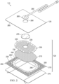
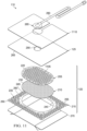
- FIG 2 is an assembly view of an example of the dressing 110 of Figure 1 , illustrating additional details that may be associated with some embodiments in which the tissue interface 120 comprises more than one layer.
- the tissue interface 120 comprises a first layer 205, a second layer 210, and a third layer 215.
- the first layer 205 may be disposed adjacent to the second layer 210
- the third layer 215 may also be disposed adjacent to the second layer 210 opposite the first layer 205.
- the first layer 205 and the second layer 210 may be stacked so that the first layer 205 is in contact with the second layer 210.
- the first layer 205 may also be bonded to the second layer 210 in some embodiments.
- the second layer 210 may be coextensive with a face of the first layer 205. In some embodiments, at least some portion of the third layer 215 may be bonded to the second layer 210.
- the cover 125, the first layer 205, the second layer 210, and the third layer 215 may be substantially transparent or semi-transparent in some examples. For example, a transmission to white light of at least 80% may be suitable for some embodiments.
- the first layer 205 generally comprises or consists essentially of a manifold or a manifold layer, which provides a means for collecting or distributing fluid across the tissue interface 120 under pressure.
- the first layer 205 may be adapted to receive negative pressure from a source and distribute negative pressure across the tissue interface 120 through multiple pathways, which may have the effect of collecting fluid from across a tissue site and drawing the fluid toward the source.
- the fluid path may be reversed or a secondary fluid path may be provided to facilitate delivering fluid, such as from a source of instillation solution, across the tissue interface 120.
- the pathways of the first layer 205 may be interconnected to improve distribution or collection of fluids.
- the first layer 205 may comprise or consist essentially of a film of fluid-impermeable material having standoffs 220.
- Polyurethane is an example of a suitable fluid-impermeable material for some applications of the first layer 205.
- the standoffs 220 may comprise a plurality of raised formations that extend above or below a plane of the first layer 205. Within each of the standoffs 220 may be an empty cavity, which may be open to the surrounding environment. For example, portions of a film of fluid-impermeable material that forms the first layer 205 may be shaped or formed into the standoffs 220.
- the standoffs 220 may be in the form of small vacuum-formed regions of the film of the first layer 205.
- each of the standoffs 220 may have a dome or hemispherical profile.
- the standoffs 220 may be in the form of raised blisters, bubbles, cells, bosses or other formations having different shapes, such as generally conical, cylindrical, tubular having a flattened or hemispherical end, or geodesic.
- the first layer 205 may further include at least one fluid passage, such as an aperture 225, which can allow fluid transfer through the first layer 205.
- the thickness of the first layer 205 may also vary according to needs of a prescribed therapy. For example, the thickness of the first layer 205 may be decreased to relieve stress on other layers and to reduce tension on peripheral tissue. The thickness of the first layer 205 can also affect the conformability of the first layer 205.
- the first layer 205 may comprise a flexible or elastic film having a thickness in a range of about 20 to 500 micrometers the standoffs 220 having a diameter of between 0.5 mm and 2.0 mm.
- the second layer 210 may comprise or consist essentially of a means for controlling or managing fluid flow.
- the second layer 210 may be a fluid control layer comprising or consisting essentially of a liquid-impermeable, elastomeric material.
- the second layer 210 may comprise or consist essentially of a flexible or elastic polymer film, such as a polyurethane film.
- the second layer 210 may comprise or consist essentially of the same material as the cover 125.
- the second layer 210 may also have a smooth or matte surface texture in some embodiments.
- a glossy or shiny finish finer or equal to a grade B3 according to the SPI (Society of the Plastics Industry) standards may be particularly advantageous for some applications.
- variations in surface height may be limited to acceptable tolerances.
- the surface of the second layer 210 may have a substantially flat surface, with height variations limited to 0.2 millimeters over a centimeter.
- a thickness of about 50 microns to about 100 microns may be suitable for some examples.
- the second layer 210 may be embossed, which can create a pattern of contact areas with a manifolding effect.
- suitable patterns include taffeta, diamond, and weave patterns.
- materials suitable for embossing include polyurethane, polyethylene, polypropylene, polyamides, and their co-polymers. A thickness of about 200 microns to about 300 microns may be suitable for some examples.
- the second layer 210 may be hydrophobic.
- the hydrophobicity of the second layer 210 may vary, but may have a contact angle with water of at least ninety degrees in some embodiments.
- the second layer 210 may have a contact angle with water of no more than 150 degrees.
- the contact angle of the second layer 210 may be in a range of at least 90 degrees to about 120 degrees, or in a range of at least 120 degrees to 150 degrees. Water contact angles can be measured using any standard apparatus.
- contact angle measuring instruments can often include an integrated system involving a level stage, liquid dropper such as a syringe, camera, and software designed to calculate contact angles more accurately and precisely, among other things.
- integrated systems may include the FT ⁇ 125, FT ⁇ 200, FT ⁇ 2000, and FT ⁇ 4000 systems, all commercially available from First Ten Angstroms, Inc., of Portsmouth, VA, and the DTA25, DTA30, and DTA100 systems, all commercially available from Kruss GmbH of Hamburg, Germany.
- water contact angles herein are measured using deionized and distilled water on a level sample surface for a sessile drop added from a height of no more than 5 cm in air at 20-25°C and 20-50% relative humidity. Contact angles herein represent averages of 5-9 measured values, discarding both the highest and lowest measured values.
- the hydrophobicity of the second layer 210 may be further enhanced with a hydrophobic coating of other materials, such as silicones and fluorocarbons, either as coated from a liquid, or plasma coated.
- the second layer 210 may also be suitable for welding to other layers, including the first layer 205.
- the second layer 210 may be adapted for welding to polyurethane foams using heat, radio frequency (RF) welding, or other methods to generate heat such as ultrasonic welding.
- RF welding may be particularly suitable for more polar materials, such as polyurethane, polyamides, polyesters and acrylates. Sacrificial polar interfaces may be used to facilitate RF welding of less polar film materials, such as polyethylene.
- the area density of the second layer 210 may vary according to a prescribed therapy or application. In some embodiments, an area density of less than 40 grams per square meter may be suitable, and an area density of about 20-30 grams per square meter may be particularly advantageous for some applications.
- the second layer 210 may comprise or consist essentially of a hydrophobic polymer, such as a polyethylene film.
- a hydrophobic polymer such as a polyethylene film.
- the simple and inert structure of polyethylene can provide a surface that interacts little, if any, with biological tissues and fluids, providing a surface that may encourage the free flow of liquids and low adherence, which can be particularly advantageous for many applications.
- polystyrene resins include polyurethanes, acrylics, polyolefin (such as cyclic olefin copolymers), polyacetates, polyamides, polyesters, copolyesters, PEBAX block copolymers, thermoplastic elastomers, thermoplastic vulcanizates, polyethers, polyvinyl alcohols, polypropylene, polymethylpentene, polycarbonate, styreneics, silicones, fluoropolymers, and acetates.
- a thickness between 20 microns and 100 microns may be suitable for many applications. Films may be clear, colored, or printed.
- More polar films suitable for laminating to a polyethylene film include polyamide, co-polyesters, ionomers, and acrylics.
- tie layers may be used, such as ethylene vinyl acetate, or modified polyurethanes.
- An ethyl methyl acrylate (EMA) film may also have suitable hydrophobic and welding properties for some configurations.
- the second layer 210 may have one or more fluid restrictions 230, which can be distributed uniformly or randomly across the second layer 210.
- the fluid restrictions 230 may be bi-directional and pressure-responsive.
- each of the fluid restrictions 230 generally may comprise or consist essentially of an elastic passage that is normally unstrained to substantially reduce liquid flow, and can expand or open in response to a pressure gradient.
- the fluid restrictions 230 may comprise or consist essentially of perforations in the second layer 210. Perforations may be formed by removing material from the second layer 210. For example, perforations may be formed by cutting through the second layer 210, which may also deform the edges of the perforations in some embodiments.
- the passages may be sufficiently small to form a seal or fluid restriction, which can substantially reduce or prevent liquid flow.
- one or more of the fluid restrictions 230 may be an elastomeric valve that is normally closed when unstrained to substantially prevent liquid flow, and can open in response to a pressure gradient.
- a fenestration in the second layer 210 may be a suitable valve for some applications. Fenestrations are generally a special case of perforations. Fenestrations may also be formed by removing material from the second layer 210, but the amount of material removed and the resulting dimensions of the fenestrations may be up to an order of magnitude less than perforations, and may not deform the edges.
- perforations may form slots in the second layer 210, and fenestrations may form slits, which are generally a special case of slots.
- the fluid restrictions 230 may comprise or consist essentially of one or more slits, slots or combinations of slits and slots in the second layer 210.
- the fluid restrictions 230 may comprise or consist of linear slots having a length less than 4 millimeters and a width less than 1 millimeter. The length may be at least 2 millimeters, and the width may be at least 0.4 millimeters in some embodiments.
- a length of about 3 millimeters and a width of about 0.8 millimeters may be particularly suitable for many applications, and a tolerance of about 0.1 millimeter may also be acceptable. Such dimensions and tolerances may be achieved with a laser cutter, for example. Slots of such configurations may function as imperfect valves that substantially reduce liquid flow in a normally closed or resting state. For example, such slots may form a flow restriction without being completely closed or sealed. The slots can expand or open wider in response to a pressure gradient to allow increased liquid flow.
- the third layer 215 may comprise or consist essentially of a sealing layer or contact layer formed from a soft, pliable material suitable for providing a fluid seal with a tissue site, such as a suitable gel material, and may have a substantially flat surface.
- the third layer 215 may comprise, without limitation, a silicone gel, a soft silicone, hydrocolloid, hydrogel, polyurethane gel, polyolefin gel, hydrogenated styrenic copolymer gel, a foamed gel, a soft closed cell foam such as polyurethanes and polyolefins coated with an adhesive, polyurethane, polyolefin, or hydrogenated styrenic copolymers.
- the third layer 215 may have a thickness between about 200 microns ( ⁇ m) and about 1000 microns ( ⁇ m). In some embodiments, the third layer 215 may have a hardness between about 5 Shore OO and about 80 Shore OO. Further, the third layer 215 may be comprised of hydrophobic or hydrophilic materials.
- the third layer 215 may be a hydrophobic-coated material.
- the third layer 215 may be formed by coating a spaced material, such as, for example, woven, nonwoven, molded, or extruded mesh with a hydrophobic material.
- the hydrophobic material for the coating may be a soft silicone, for example.
- the third layer 215 may have a periphery 235 surrounding or around a treatment aperture 240, and apertures 245 in the periphery 235 disposed around the treatment aperture 240.
- the treatment aperture 240 may be complementary or correspond to a surface area of the first layer 205 in some examples.
- the treatment aperture 240 may form a frame, window, or other opening around a surface of the first layer 205.
- the third layer 215 may also have corners 250 and edges 255. The corners 250 and the edges 255 may be part of the periphery 235.
- the third layer 215 may have an interior border 260 around the treatment aperture 240, which may be substantially free of the apertures 245, as illustrated in the example of Figure 2 .
- the treatment aperture 240 may be symmetrical and centrally disposed in the third layer 215, forming an open central window.
- the apertures 245 may be formed by cutting, perforating, or by application of local RF or ultrasonic energy, for example, or by other suitable techniques for forming an opening or perforation in the third layer 215.
- the apertures 245 may have a uniform distribution pattern, or may be randomly distributed on the third layer 215.
- the apertures 245 in the third layer 215 may have many shapes, including circles, squares, stars, ovals, polygons, slits, complex curves, rectilinear shapes, triangles, for example, or may have some combination of such shapes.
- each of the apertures 245 may have uniform or similar geometric properties.
- each of the apertures 245 may be circular apertures, having substantially the same diameter.
- each of the apertures 245 may have a diameter of about 1 millimeter to about 50 millimeters. In other embodiments, the diameter of each of the apertures 245 may be about 1 millimeter to about 20 millimeters.
- geometric properties of the apertures 245 may vary.
- the diameter of the apertures 245 may vary depending on the position of the apertures 245 in the third layer 215.
- the apertures 245 disposed in the periphery 235 may have a diameter between about 5 millimeters and about 10 millimeters. A range of about 7 millimeters to about 9 millimeters may be suitable for some examples.
- the apertures 245 disposed in the corners 250 may have a diameter between about 7 millimeters and about 8 millimeters.
- At least one of the apertures 245 in the periphery 235 of the third layer 215 may be positioned at the edges 255 of the periphery 235, and may have an interior cut open or exposed at the edges 255 that is in fluid communication in a lateral direction with the edges 255.
- the lateral direction may refer to a direction toward the edges 255 and in the same plane as the third layer 215.
- the apertures 245 in the periphery 235 may be positioned proximate to or at the edges 255 and in fluid communication in a lateral direction with the edges 255.
- the apertures 245 positioned proximate to or at the edges 255 may be spaced substantially equidistant around the periphery 235 as shown in the example of Figure 2 .
- the spacing of the apertures 245 proximate to or at the edges 255 may be irregular.
- the dressing 110 may further include an attachment device, such as an adhesive 265.
- the adhesive 265 may be, for example, a medically-acceptable, pressure-sensitive adhesive that extends about a periphery, a portion, or an entire surface of the cover 125.
- the adhesive 265 may be an acrylic adhesive having a coating weight between 25-65 grams per square meter (g.s.m.). Thicker adhesives, or combinations of adhesives, may be applied in some embodiments to improve the seal and reduce leaks.
- such a layer of the adhesive 265 may be continuous or discontinuous. Discontinuities in the adhesive 265 may be provided by apertures or holes (not shown) in the adhesive 265.
- the apertures or holes in the adhesive 265 may be formed after application of the adhesive 265 or by coating the adhesive 265 in patterns on a carrier layer, such as, for example, a side of the cover 125. Apertures or holes in the adhesive 265 may also be sized to enhance the MVTR of the dressing 110 in some example embodiments.
- the dressing 110 may include a release liner 270 to protect the adhesive 265 prior to use.
- the release liner 270 may also provide stiffness to assist with, for example, deployment of the dressing 110.
- the release liner 270 may be, for example, a casting paper, a film, or polyethylene.
- the release liner 270 may be a polyester material such as polyethylene terephthalate (PET), or similar polar semi-crystalline polymer.
- PET polyethylene terephthalate
- the use of a polar semi-crystalline polymer for the release liner 270 may substantially preclude wrinkling or other deformation of the dressing 110.
- the polar semi-crystalline polymer may be highly orientated and resistant to softening, swelling, or other deformation that may occur when brought into contact with components of the dressing 110, or when subjected to temperature or environmental variations, or sterilization.
- a release agent may be disposed on a side of the release liner 270 that is configured to contact the second layer 210.
- the release agent may be a silicone coating and may have a release factor suitable to facilitate removal of the release liner 270 by hand and without damaging or deforming the dressing 110.
- the release agent may be a fluorocarbon or a fluorosilicone, for example.
- the release liner 270 may be uncoated or otherwise used without a release agent.
- the dressing 110 may additionally include a spacer manifold 275.
- the spacer manifold 275 may have a structure that is similar to the first layer 205 with perforations between the standoffs.
- the spacer manifold may comprise or consist essentially of a porous material having interconnected fluid pathways. Examples of suitable porous material that comprise or can be adapted to form interconnected fluid pathways (e.g., channels) may include cellular foam, including open-cell foam such as reticulated foam; porous tissue collections; and other porous material such as gauze or felted mat that generally include pores, edges, and/or walls. Liquids, gels, and other foams may also include or be cured to include apertures and fluid pathways.
- the spacer manifold 275 may additionally or alternatively comprise projections that form interconnected fluid pathways.
- the spacer manifold 275 may be molded to provide surface projections that define interconnected fluid pathways, or may have standoffs similar or analogous to the standoffs 220.
- the spacer manifold 275 may comprise or consist essentially of a reticulated foam.
- a reticulated foam having a free volume of at least 90% may be suitable for many applications, and a foam having an average pore size in a range of 400-600 microns may be particularly suitable for some types of therapy.
- the tensile strength of the spacer manifold 275 may also vary. For example, the tensile strength of a foam may be increased for instillation of topical treatment solutions.
- the 25% compression load deflection of the spacer manifold 275 may be at least 0.35 pounds per square inch, and the 65% compression load deflection may be at least 0.43 pounds per square inch.
- the tensile strength of the spacer manifold 275 may be at least 10 pounds per square inch.
- the spacer manifold 275 may have a tear strength of at least 2.5 pounds per inch.
- the spacer manifold 275 may be a foam comprised of polyols such as polyester or polyether, isocyanate such as toluene diisocyanate, and polymerization modifiers such as amines and tin compounds.
- the spacer manifold 275 may be a reticulated polyurethane foam such as used in GRANUFOAM TM dressing or V.A.C. VERAFLO TM dressing, both available from KCI of San Antonio, Texas.
- spacer manifold 275 may include non-woven fabrics (Libeltex, Freudenberg), three-dimensional (3D) polymeric structures (molded polymers, embossed and formed films, and fusion bonded films [Supracore]), and mesh, for example.
- non-woven fabrics Libeltex, Freudenberg
- 3D polymeric structures molded polymers, embossed and formed films, and fusion bonded films [Supracore]
- mesh for example.
- the spacer manifold 275 may include a 3D textile, such as various textiles commercially available from Baltex, Muller, and Heathcoates.
- a 3D textile of polyester fibers may be particularly advantageous for some embodiments.
- the spacer manifold 275 may comprise or consist essentially of a three-dimensional weave of polyester fibers.
- the fibers may be elastic in at least two dimensions.
- a puncture-resistant fabric of polyester and cotton fibers having a weight of about 650 grams per square meter and a thickness of about 1-2 millimeters may be particularly advantageous for some embodiments.
- Such a puncture-resistant fabric may have a warp tensile strength of about 330-340 kilograms and a weft tensile strength of about 270-280 kilograms in some embodiments.
- Another particularly suitable material may be a polyester spacer fabric having a weight of about 470 grams per square meter, which may have a thickness of about 4-5 millimeters in some embodiments.
- Such a spacer fabric may have a compression strength of about 20-25 kilopascals (at 40% compression).
- Figure 2 also illustrates one example of a fluid conductor 280 and a dressing interface 285.
- the fluid conductor 280 may be a flexible tube, which can be fluidly coupled on one end to the dressing interface 285.
- the dressing interface 285 may be an elbow connector, as shown in the example of Figure 2 , which can be placed over an aperture 290 in the cover 125 to provide a fluid path between the fluid conductor 280 and the tissue interface 120.
- the dressing interface 285 may be larger than the aperture 290, and in some embodiments may be coextensive with the spacer manifold 275.
- the aperture 225, the spacer manifold 275, and the aperture 290 may be axially aligned in some embodiments, and the spacer manifold 275 may be disposed between the aperture 225 and the aperture 290.
- the aperture 225, the spacer manifold 275, and the aperture 290 may have similar shapes in some embodiments.
- the spacer manifold 275 may have a shape similar to the second layer 210.
- the spacer manifold 275 is preferably larger than the aperture 225 and the aperture 290.
- the spacer manifold 275 may have a thickness in a range of about 0.5 millimeters to about 10 millimeters.
- One or more of the components of the dressing 110 may additionally be treated with an antimicrobial agent in some embodiments.
- first layer 205, the second layer 210, or both may be a polymer coated or mixed with an antimicrobial agent.
- the fluid conductor 280 may additionally or alternatively be treated with one or more antimicrobial agents.
- Suitable antimicrobial agents may include, for example, metallic silver, PHMB, iodine or its complexes and mixes such as povidone iodine, copper metal compounds, chlorhexidine, or some combination of these materials.
- one or more of the components may be coated with a mixture that may include citric acid and collagen, which can reduce bio-films and infections.
- the first layer 205 may be coated with such a mixture.
- the first layer 205 may be made from or coated with a material that can bind with and retain bacteria, which can prevent the bacteria from multiplying.
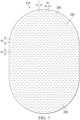
- Figure 3 is a top view of the dressing 110 in the example of Figure 2 , as assembled, illustrating additional details that may be associated with some embodiments.
- the cover 125 and the third layer 215 may have substantially the same perimeter shape and dimensions, so that the cover 125 and the third layer 215 are coextensive in some examples.
- the first layer 205 may be centrally disposed over the third layer 215, such as over the treatment aperture 240.
- the cover 125 may be disposed over the first layer 205 and the spacer manifold 275, with the aperture 290 aligned over the spacer manifold 275.
- the cover 125 may be substantially transparent, allowing visibility of at least some of the apertures 245 and the fluid restrictions 230 in some embodiments.
- at least some of the fluid restrictions 230 may be offset from the standoffs 220.
- the fluid restrictions 230 may be registered with the standoffs 220 so that a substantial portion of the fluid restrictions 230 do not align with the standoffs 220.
- the standoffs 220 may not align with any of the fluid restrictions 230.
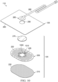
- Figure 4 is a bottom view of the dressing 110 of Figure 3 , illustrating additional details that may be associated with some embodiments.
- the release liner 270 is removed in the example of Figure 4 .
- a substantial number of the fluid restrictions 230 may be aligned or otherwise exposed through the treatment aperture 240, and at least some portion of the first layer 205 may be disposed adjacent to the fluid restrictions 230 opposite the treatment aperture 240.
- the first layer 205 and the second layer 210 may be substantially aligned with the treatment aperture 240, or may extend across the treatment aperture 240.
- the first layer 205 may have a first edge 405, and the second layer 210 may have a second edge 410.
- the first edge 405 and the second edge 410 may have substantially the same shape so that adjacent faces of the first layer 205 and the second layer 210 are geometrically similar.
- the first edge 405 and the second edge 410 may also be congruent in some examples, so that adjacent faces of the first layer 205 and the second layer 210 are substantially coextensive and have substantially the same surface area.
- the first edge 405 defines a larger face of the first layer 205 than the face of the second layer 210 defined by the second edge 410, and the larger face of the first layer 205 extends past the smaller face of the second edge 410.
- the faces defined by the first edge 405, the second edge 410, or both may also be geometrically similar to the treatment aperture 240 in some embodiments, as illustrated in the example of Figure 4 , and may be larger than the treatment aperture 240.
- the third layer 215 may have an overlay margin 415 around the treatment aperture 240, which may have an additional adhesive disposed therein.
- the treatment aperture 240 may be an ellipse or a stadium in some embodiments.
- the treatment aperture 240 may have an area that is equal to about 20% to about 80% of the area of the third layer 215 in some examples.
- the treatment aperture 240 may also have an area that is equal to about 20% to about 80% of the area of a face of defined by the first edge 405 of the first layer 205.
- a width of about 90 millimeters to about 110 millimeters and a length of about 150 millimeters to about 160 millimeters may be suitable for some embodiments of the treatment aperture 240.
- the width of the treatment aperture 240 may be about 100 millimeters, and the length may be about 155 millimeters.
- a suitable width for the overlay margin 415 may be about 2 millimeters to about 3 millimeters.
- the overlay margin 415 may be coextensive with an area defined between the treatment aperture 240 and the first edge 405, and the adhesive may secure the first layer 205, the second layer 210, or both to the third layer 215.
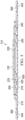
- Figure 5 is a section view of the dressing 110 of Figure 3 , taken along line 5-5, illustrating additional details that may be associated with some embodiments.
- the cover 125, the first layer 205, the second layer 210, the third layer 215, and the spacer manifold 275 may be assembled in a stacked relationship.
- the cover 125 may be coupled to the third layer 215 around the first layer 205 and the second layer 210, so that the cover 125 and the third layer 215 substantially enclose the first layer 205, the second layer 210, and the spacer manifold 275.
- the second layer 210 may be exposed through the treatment aperture 240, and at least some of the adhesive 265 can be exposed through the apertures 245.
- the first layer 205 may be oriented so that the standoffs 220 are adjacent to the second layer 210, which can create a plurality of spaces 505 between the first layer 205 and the second layer 210.
- the spaces 505 may form interconnected fluid pathways between the fluid restrictions 230 and the aperture 225.
- the spacer manifold 275 is also disposed between the first layer 205 and the cover 125. As illustrated, the spacer manifold 275 may be disposed over the aperture 225, which can separate the cover 125 and the second layer 210 and provide additional fluid pathways.
- the first layer 205 may be formed of a single sheet or film of fluid-impermeable material, which may have the standoffs 220 formed thereon.
- the standoffs 220 may be formed in the first layer 205 by applying a vacuum to the film of fluid-impermeable material of the first layer 205.
- the standoffs may have dimensions that depend on the particular application of the dressing 110.
- the first layer 205 may comprise a film having a thickness of about 500 microns, and each of the standoffs may have a height between approximately 1 millimeter and 4 millimeters. A width of between approximately 1 millimeter and 4 millimeters may also be suitable for some embodiments.
- the standoffs 220 may measure approximately 3 millimeters in height and approximately 3 millimeters in diameter. Additionally, the standoffs 220 may be distributed across the first layer 205 in a uniform grid or array having a pitch of approximately 3.5 millimeters to about 4 millimeters. A pitch of about 3.75 millimeters may be particularly suitable for some examples. The spacing may be modified to alter flow characteristics and transparency, for example.
- Figure 6 is an assembly view of another example of the dressing 110 of Figure 1 , illustrating additional details that may be associated with some embodiments. As illustrated in Figure 6 , some examples of the third layer 215 may not have the treatment aperture 240, and the apertures 245 may be distributed in a uniform pattern across the third layer 215.
- Figure 7 is a schematic view of an example of the second layer 210, illustrating additional details that may be associated with some embodiments.
- the fluid restrictions 230 may each consist essentially of one or more slits having a length L. A length of about 3 millimeters may be particularly suitable for some embodiments.
- Figure 7 additionally illustrates an example of a uniform distribution pattern of the fluid restrictions 230.
- the fluid restrictions 230 are substantially coextensive with the second layer 210, and are distributed across the second layer 210 in a grid of parallel rows and columns, in which the slits are also mutually parallel to each other. In some embodiments, the rows may be spaced a distance D 1.
- a distance of about 3 millimeters on center may be suitable for some embodiments.
- the fluid restrictions 230 within each of the rows may be spaced a distance D2, which may be about 3 millimeters on center in some examples.
- the fluid restrictions 230 in adjacent rows may be aligned or offset in some embodiments. For example, adjacent rows may be offset, as illustrated in Figure 7 , so that the fluid restrictions 230 are aligned in alternating rows and separated by a distance D3, which may be about 6 millimeters in some embodiments.
- the spacing of the fluid restrictions 230 may vary in some embodiments to increase the density of the fluid restrictions 230 according to therapeutic requirements.
- Figure 8 is a schematic view of an example configuration of the apertures 245, illustrating additional details that may be associated with some embodiments of the third layer 215.
- the apertures 245 are generally circular and have a diameter D4, which may be about 6 millimeters to about 8 millimeters in some embodiments. A diameter D4 of about 7 millimeters may be particularly suitable for some embodiments.
- Figure 8 also illustrates an example of a uniform distribution pattern of the apertures 245.
- the apertures 245 are distributed in a grid of parallel rows and columns. Within each row and column, the apertures 245 may be equidistant from each other, as illustrated in the example of Figure 8.
- Figure 8 illustrates one example configuration that may be particularly suitable for many applications, in which the apertures 245 are spaced a distance D5 apart along each row and column, with an offset of D6.
- the distance D5 may be about 9 millimeters to about 10 millimeters
- the offset D6 may be about 8 millimeters to about 9 millimeters.
- Figure 9 is a schematic view of the apertures 245 as configured in the example of Figure 8 overlaid on the second layer 210 of Figure 7 , illustrating additional details that may be associated with some example embodiments of the tissue interface 120.
- more than one of the fluid restrictions 230 may be aligned, overlapping, in registration with, or otherwise fluidly coupled to the apertures 245 in some embodiments.
- one or more of the fluid restrictions 230 may be only partially registered with the apertures 245.
- the apertures 245 in the example of Figure 9 are generally sized and configured so that at least four of the fluid restrictions 230 are registered with each one of the apertures 245. In other examples, one or more of the fluid restrictions 230 may be registered with more than one of the apertures 245.
- any one or more of the fluid restrictions 230 may be a perforation or a fenestration that extends across two or more of the apertures 245. Additionally or alternatively, one or more of the fluid restrictions 230 may not be registered with any of the apertures 245.
- the apertures 245 may be sized to expose a portion of the second layer 210, the fluid restrictions 230, or both through the third layer 215.
- the apertures 245 in the example of Figure 9 are generally sized to expose more than one of the fluid restrictions 230. Some or all of the apertures 245 may be sized to expose two or three of the fluid restrictions 230.
- the length L of each of the fluid restrictions 230 may be substantially smaller than the width W of each of the apertures 245. More generally, the average dimensions of the fluid restrictions 230 are substantially smaller than the average dimensions of the apertures 245.
- the apertures 245 may be elliptical, and the length of each of the fluid restrictions 230 may be substantially smaller than the major axis or the minor axis. In some embodiments, though, the dimensions of the fluid restrictions 230 may exceed the dimensions of the apertures 245, and the size of the apertures 245 may limit the effective size of the fluid restrictions 230 exposed to the lower surface of the dressing 110.
- Figure 10 is an assembly view of another example of the dressing 110 of Figure 1 , illustrating additional details that may be associated with some embodiments. As illustrated in Figure 10 , some examples of the dressing 110 may not have the third layer 215.
- Figure 10 also illustrates another example of the aperture 225.
- the aperture 225 comprises a primary aperture 1005 and one or more auxiliary apertures 1010 around the primary aperture 1005.
- the primary aperture 1005 may be larger than the auxiliary apertures 1010 in some embodiments.
- the primary aperture 1005 in Figure 10 may have a width of about 10 millimeters, and each of the auxiliary apertures 1010 may have a width of about 3 millimeters.
- Figure 11 is an assembly view of another example of the dressing 110 of Figure 1 , illustrating additional details that may be associated with some embodiments.
- the first layer 205 comprises a plurality fluid passages, in addition to or instead of the aperture 225.
- the fluid passages may comprise apertures 1105 adjacent to the standoffs 220.
- the apertures 1105 may be formed in the portions of the first layer 205 that are between the standoffs 220 and may extend through the first layer 205.
- the number of the apertures 1105 may vary depending on the type of application.
- the apertures 1105 may have different shapes, such as, for example, circular, elliptical, rectangular, or other irregular shape.
- the apertures 1105 may have a width, diameter, major axis, or length between about 0.5 mm and 1.5 mm. A diameter of about 1 millimeter may be suitable for some embodiments.
- the apertures 1105 may be formed by cutting or heat-perforating the first layer 205.
- some embodiments of the dressing 110 may comprise a visual screen 1110, which can obscure a tissue site from patient view and be removed for assessment without disturbing the dressing 110.
- a suitable screen may comprise or consist essentially of highly-breathable polymer film that is opaque or at least partially optically occlusive.
- a visually occlusive polyurethane film may be suitable for some examples.
- the visual screen may be assembled to the cover 125 and coated with a re-sealable adhesive, such as a pattern-coated silicone or polyurethane gel.
- the dressing 110 may be bonded or otherwise secured to one another with a solvent or non-solvent adhesive, or with heat bonding, for example, without adversely affecting fluid management.
- the second layer 210 or the first layer 205 may be coupled to the interior border 260 or the overlay margin 415 of the third layer 215 in any suitable manner, such as with a weld or an adhesive, for example.
- the cover 125, the first layer 205, the second layer 210, the third layer 215, the spacer manifold 275, or various combinations may be assembled before application or in situ.
- the second layer 210 may be laminated to the first layer 205 in some embodiments.
- the cover 125 may be disposed over the first layer 205 and coupled to the third layer 215 around the first layer 205 in some embodiments.
- one or more layers of the tissue interface 120 may be coextensive.
- the second layer 210 may be cut flush with the edge of the first layer 205.
- the dressing 110 may be provided as a composite dressing.
- the third layer 215 may be coupled to the cover 125 to enclose the first layer 205 and the second layer 210, wherein the third layer 215 may be configured to face a tissue site.
- the first layer 205, the second layer 210, and the third layer 215 may be coextensive, and the edges of each may be exposed around a perimeter of the tissue interface 120 to facilitate customization.
- the release liner 270 may be removed to expose a lower surface of the tissue interface 120.
- removing the release liner 270 may expose the third layer 215.
- the tissue interface 120 may be cut or trimmed as appropriate.
- the tissue interface 120 can be placed within, over, on, or otherwise proximate to a tissue site, particularly a surface tissue site and adjacent epidermis.
- the treatment aperture 240 of the third layer 215 may be positioned adjacent to, proximate to, or covering a tissue site.
- at least some portion of the second layer 210, the fluid restrictions 230, or both may be exposed to a tissue site through the treatment aperture 240, the apertures 245, or both.
- the periphery 235 of the third layer 215 may be positioned adjacent to or proximate to tissue around or surrounding the tissue site.
- the third layer 215 may be sufficiently tacky to hold the dressing 110 in position, while also allowing the dressing 110 to be removed or re-positioned without trauma to the tissue site.
- Removing the release liner 270 can also expose the adhesive 265, and the cover 125 may be attached to an attachment surface, such as the periphery 235 or other area around the treatment aperture 240 and the first layer 205.
- the adhesive 265 may also be attached to epidermis peripheral to a tissue site, around the first layer 205 and the second layer 210.
- the adhesive 265 may be in fluid communication with an attachment surface through the apertures 245 in at least the periphery 235 of the third layer 215.
- the adhesive 265 may also be in fluid communication with the edges 255 through the apertures 245 exposed at the edges 255.
- the dressing 110 may be secured to the tissue site.
- a cover may be bonded to an attachment surface around the edges of the tissue interface 120 to seal any exposed edges.
- the adhesive 265 may be pressed through the apertures 245 to bond the dressing 110 to the attachment surface.
- the apertures 245 at the edges 255 may permit the adhesive 265 to flow around the edges 255 for enhancing the adhesion of the edges 255 to an attachment surface.
- the apertures 245 may be sized to control the amount of the adhesive 265 exposed through the apertures 245.
- the relative sizes of the apertures 245 may be configured to maximize the surface area of the adhesive 265 exposed and in fluid communication through the apertures 245 at the corners 250.
- the edges 255 may intersect at substantially a right angle, or about 90 degrees, to define the corners 250.
- the corners 250 may have a radius of about 10 millimeters.
- three of the apertures 245 may be positioned in a triangular configuration at the corners 250 to maximize the exposed surface area for the adhesive 265.
- the size and number of the apertures 245 in the corners 250 may be adjusted as necessary, depending on the chosen geometry of the corners 250, to maximize the exposed surface area of the adhesive 265.
- the apertures 245 at the corners 250 may be fully contained within the third layer 215, substantially precluding fluid communication in a lateral direction exterior to the corners 250.
- the apertures 245 at the corners 250 being fully contained within the third layer 215 may substantially preclude fluid communication of the adhesive 265 exterior to the corners 250, and may provide improved handling of the dressing 110 during deployment at a tissue site.
- the exterior of the corners 250 being substantially free of the adhesive 265 may increase the flexibility of the corners 250 to enhance comfort.
- the bond strength of the adhesive 265 may vary based on the configuration of the third layer 215.
- the bond strength may vary based on the size of the apertures 245.
- the bond strength may be inversely proportional to the size of the apertures 245.
- the bond strength may vary in different locations, for example, if the size of the apertures 245 varies. For example, a lower bond strength in combination with larger apertures 245 may provide a bond comparable to a higher bond strength in locations having smaller apertures 245.
- the geometry and dimensions of the tissue interface 120, the cover 125, or both may vary to suit a particular application or anatomy.
- the geometry or dimensions of the tissue interface 120 and the cover 125 may be adapted to provide an effective and reliable seal against challenging anatomical surfaces, such as an elbow or heel, at and around a tissue site.
- the dimensions may be modified to increase the surface area for the third layer 215 to enhance the movement and proliferation of epithelial cells at a tissue site and reduce the likelihood of granulation tissue in-growth.
- the dressing 110 can provide a sealed therapeutic environment proximate to a tissue site, substantially isolated from the external environment, and the negative-pressure source 105 can reduce the pressure in the sealed therapeutic environment.
- the treatment aperture 240 can provide an open area for delivery of negative pressure and passage of wound fluid through the second layer 210 and the first layer 205.
- the dressing 110 may permit re-application or repositioning, to correct air leaks caused by creases and other discontinuities in the dressing 110, for example. The ability to rectify leaks may increase the efficacy of the therapy and reduce power consumption in some embodiments.
- the dressing interface 285 may be disposed over the aperture 290 and attached to the cover 125.
- the fluid conductor 280 may be fluidly coupled to the dressing interface 285 and to the negative-pressure source 105.
- Negative pressure can be applied through the aperture 290 to the tissue interface 120.
- the spacer manifold 275 may prevent the first layer 205 from being drawn or pushed into the aperture 290 and sealing off the tissue interface from the negative-pressure source 105.
- the standoffs 220 are preferably resistant to collapsing under therapeutic levels of negative pressure.
- the cover 125 in combination with the standoffs 220 may effectively form closed cells that can increase the resistance to collapse.
- Negative pressure applied through the tissue interface 120 can also create a negative pressure differential across the fluid restrictions 230 in the second layer 210, which can open or expand the fluid restrictions 230.
- the fluid restrictions 230 may comprise substantially closed fenestrations through the second layer 210
- a pressure gradient across the fenestrations can strain the adjacent material of the second layer 210 and increase the dimensions of the fenestrations to allow liquid movement through them, similar to the operation of a duckbill valve.
- Opening the fluid restrictions 230 can allow exudate and other liquid movement through the fluid restrictions 230 into the first layer 205.
- the first layer 205 can provide passage of negative pressure and wound fluid, which can be collected in the container 115.
- Changes in pressure can also cause the first layer 205 to expand and contract.
- the second layer 210, the third layer 215, or both may protect the epidermis from irritation that could be caused by expansion, contraction, or other movement of the first layer 205.
- the overlay margin 415 may be disposed between the first layer 205 and epidermis around a tissue site.
- the second layer 210 and the third layer 215 can also substantially reduce or prevent exposure of a tissue site to the first layer 205, which can inhibit growth of tissue into the first layer 205.
- the second layer 210 may cover the treatment aperture 240 to prevent direct contact between the first layer 205 and a tissue site.
- the pressure differential across the fluid restrictions 230 can dissipate, allowing the fluid restrictions 230 to close and prevent exudate or other liquid from returning to the tissue site through the second layer 210.
- a filler may also be disposed between a tissue site and the third layer 215.
- a tissue site is a surface wound
- a wound filler may be applied interior to the periwound
- the third layer 215 may be disposed over the periwound and the wound filler.
- the filler may be a manifold, such as an open-cell foam.
- the filler may comprise or consist essentially of the same material as the first layer 205 or the spacer manifold 275 in some embodiments.
- instillation solution or other fluid may be distributed to the dressing 110, which can increase the pressure in the tissue interface 120.
- the increased pressure in the tissue interface 120 can create a positive pressure differential across the fluid restrictions 230 in the second layer 210, which can open the fluid restrictions 230 to allow the instillation solution or other fluid to be distributed to the tissue site.
- the systems, apparatuses, and methods described herein may provide significant advantages.
- some dressings for negative-pressure therapy can require time and skill to be properly sized and applied to achieve a good fit and seal.
- some embodiments of the dressing 110 provide a negative-pressure dressing that is simple to apply, reducing the time to apply and remove.
- the dressing 110 may be a fully-integrated negative-pressure therapy dressing that can be applied to a tissue site (including on the periwound) in one step, without being cut to size, while still providing or improving many benefits of other negative-pressure therapy dressings that require sizing.
- Such benefits may include good manifolding, beneficial granulation, minimal in-growth into the tissue interface, protection of the peripheral tissue from maceration, protection of the tissue site from shedding materials, and a low-trauma and high-seal bond. These characteristics may be particularly advantageous for surface wounds having moderate depth and medium-to-high levels of exudate.
- Some embodiments of the dressing 110 may remain on the tissue site for at least 5 days, and some embodiments may remain for at least 7 days.
- Antimicrobial agents in the dressing 110 may extend the usable life of the dressing 110 by reducing or eliminating infection risks that may be associated with extended use, particularly use with infected or highly exuding wounds.
- Some embodiments of the dressing 110 may also provide a means to create micro-strain on a tissue site, and both primary and secondary manifolding of fluids.
- some embodiments of the second layer 210 may be embossed to provide secondary manifolding, which can manifold small volumes of fluid at low pressures, and the first layer 205 can provide primary manifolding to move higher volumes of fluid at higher pressure.
- some embodiments of the dressing 110 can provide a substantially transparent structure, which can allow a tissue site to be observed or visualized without disrupting the integrity of the dressing 110 or treatment.
Landscapes
- Health & Medical Sciences (AREA)
- Heart & Thoracic Surgery (AREA)
- Biomedical Technology (AREA)
- General Health & Medical Sciences (AREA)
- Veterinary Medicine (AREA)
- Vascular Medicine (AREA)
- Engineering & Computer Science (AREA)
- Public Health (AREA)
- Animal Behavior & Ethology (AREA)
- Life Sciences & Earth Sciences (AREA)
- Hematology (AREA)
- Anesthesiology (AREA)
- Oral & Maxillofacial Surgery (AREA)
- Surgery (AREA)
- Pulmonology (AREA)
- Media Introduction/Drainage Providing Device (AREA)
Description
- The invention set forth in the appended claims relates generally to tissue treatment systems and more particularly, but without limitation, to a transparent dressing for negative-pressure therapy.
- Clinical studies and practice have shown that reducing pressure in proximity to a tissue site can augment and accelerate growth of new tissue at the tissue site. The applications of this phenomenon are numerous, but it has proven particularly advantageous for treating wounds. Regardless of the etiology of a wound, whether trauma, surgery, or another cause, proper care of the wound is important to the outcome. Treatment of wounds or other tissue with reduced pressure may be commonly referred to as "negative-pressure therapy," but is also known by other names, including "negative-pressure wound therapy," "reduced-pressure therapy," "vacuum therapy," "vacuum-assisted closure," and "topical negative-pressure," for example. Negative-pressure therapy may provide a number of benefits, including migration of epithelial and subcutaneous tissues, improved blood flow, and micro-deformation of tissue at a wound site. Together, these benefits can increase development of granulation tissue and reduce healing times.
- There is also widespread acceptance that cleansing a tissue site can be highly beneficial for new tissue growth. For example, a wound or a cavity can be washed out with a liquid solution for therapeutic purposes. These practices are commonly referred to as "irrigation" and "lavage" respectively. "Instillation" is another practice that generally refers to a process of slowly introducing fluid to a tissue site and leaving the fluid for a prescribed period of time before removing the fluid. For example, instillation of topical treatment solutions over a wound bed can be combined with negative-pressure therapy to further promote wound healing by loosening soluble contaminants in a wound bed and removing infectious material. As a result, soluble bacterial burden can be decreased, contaminants removed, and the wound cleansed.
- While the clinical benefits of negative-pressure therapy and/or instillation therapy are widely known, improvements to therapy systems, components, and processes may benefit healthcare providers and patients.
-
US2018/0353663 discloses a dressing or wound filler comprising a laminate structure of film materials. -
US2016/0022885 disclose a negative pressure treatment system including an elongated layer of material and a lip to be placed in contact with a wound, wherein the elongated layer of material is for wrapping around a wound filler. -
US2018/0353339 discloses a dressing for treating a tissue site with negative pressure including a first layer having fenestrations with a raised edge. - New and useful systems, apparatuses, and methods for treating a tissue site in a negative-pressure therapy environment are set forth in the appended claims. Illustrative embodiments are also provided to enable a person skilled in the art to make and use the claimed subject matter.
- The invention is defined by the appended claims, in which there is required a dressing for treating a tissue site with negative pressure, the dressing comprising: a cover having an aperture; a first layer comprising a plurality of standoffs and at least one fluid passage; a second layer comprising a plurality of fluid elastomeric valves; and a third layer comprising a treatment aperture; wherein the cover, the first layer, the second layer, and the third layer are assembled in a stacked relationship with the first layer and the second layer disposed between the cover and the third layer, at least some of the elastomeric valves are exposed through the treatment aperture, the aperture in the cover is fluidly coupled to at least one fluid passage in the first layer, and the standoffs are disposed adjacent to the second layer and form a plurality of spaces between the first layer and the second layer.
- A selection of optional features is set out in the dependent claims.
-
-
Figure 1 is a functional block diagram of an example embodiment of a therapy system that can provide negative-pressure treatment and instillation treatment in accordance with this specification; -
Figure 2 is an assembly view of an example of a dressing that may be associated with some embodiments of the therapy system ofFigure 1 ; -
Figure 3 is a top view of the dressing ofFigure 2 , as assembled; -
Figure 4 is a bottom view of the dressing ofFigure 3 ; -
Figure 5 is a section view of the dressing ofFigure 3 ; -
Figure 6 is an assembly view of another example of a dressing that may be associated with some embodiments of the therapy system ofFigure 1 ; -
Figure 7 is a schematic view of an example of a layer that may be associated with some dressings; -
Figure 8 is a schematic view of an example configuration of apertures that may be associated with a layer in some dressings; -
Figure 9 is a schematic view of the apertures ofFigure 8 overlaid on the layer ofFigure 7 ; -
Figure 10 is an assembly view of another example of a dressing that may be associated with some embodiments of the therapy system ofFigure 1 ; and -
Figure 11 is an assembly view of another example of a dressing that may be associated with some embodiments of the therapy system ofFigure 1 . - The following description of example embodiments provides information that enables a person skilled in the art to make and use the subject matter set forth in the appended claims, but it may omit certain details already well-known in the art. The following detailed description is, therefore, to be taken as illustrative and not limiting.
- The example embodiments may also be described herein with reference to spatial relationships between various elements or to the spatial orientation of various elements depicted in the attached drawings. In general, such relationships or orientation assume a frame of reference consistent with or relative to a patient in a position to receive treatment. However, as should be recognized by those skilled in the art, this frame of reference is merely a descriptive expedient rather than a strict prescription.
-
Figure 1 is a simplified functional block diagram of an example embodiment of atherapy system 100 that can provide negative-pressure therapy with instillation of topical treatment solutions to a tissue site in accordance with this specification. - The term "tissue site" in this context broadly refers to a wound, defect, or other treatment target located on or within tissue, including, but not limited to, bone tissue, adipose tissue, muscle tissue, neural tissue, dermal tissue, vascular tissue, connective tissue, cartilage, tendons, or ligaments. A wound may include chronic, acute, traumatic, subacute, and dehisced wounds, partial-thickness burns, ulcers (such as diabetic, pressure, or venous insufficiency ulcers), flaps, and grafts, for example. The term "tissue site" may also refer to areas of any tissue that are not necessarily wounded or defective, but are instead areas in which it may be desirable to add or promote the growth of additional tissue. For example, negative pressure may be applied to a tissue site to grow additional tissue that may be harvested and transplanted.
- The
therapy system 100 may include a source or supply of negative pressure, such as a negative-pressure source 105, and one or more distribution components. A distribution component is preferably detachable and may be disposable, reusable, or recyclable. A dressing, such as adressing 110, and a fluid container, such as acontainer 115, are examples of distribution components that may be associated with some examples of thetherapy system 100. As illustrated in the example ofFigure 1 , thedressing 110 may comprise or consist essentially of atissue interface 120, acover 125, or both in some embodiments. - A fluid conductor is another illustrative example of a distribution component. A "fluid conductor," in this context, broadly includes a tube, pipe, hose, conduit, or other structure with one or more lumina or open pathways adapted to convey a fluid between two ends. Typically, a tube is an elongated, cylindrical structure with some flexibility, but the geometry and rigidity may vary. Moreover, some fluid conductors may be molded into or otherwise integrally combined with other components. Distribution components may also include or comprise interfaces or fluid ports to facilitate coupling and de-coupling other components. In some embodiments, for example, a dressing interface may facilitate coupling a fluid conductor to the
dressing 110. For example, such a dressing interface may be a SENSAT.R.A.C.™ Pad available from Kinetic Concepts, Inc. of San Antonio, Texas. - The
therapy system 100 may also include a regulator or controller, such as acontroller 130. Additionally, thetherapy system 100 may include sensors to measure operating parameters and provide feedback signals to thecontroller 130 indicative of the operating parameters. As illustrated inFigure 1 , for example, thetherapy system 100 may include afirst sensor 135 and asecond sensor 140 coupled to thecontroller 130. - The
therapy system 100 may also include a source of instillation solution. For example, asolution source 145 may be fluidly coupled to thedressing 110, as illustrated in the example embodiment ofFigure 1 . Thesolution source 145 may be fluidly coupled to a positive-pressure source such as a positive-pressure source 150, a negative-pressure source such as the negative-pressure source 105, or both in some embodiments. A regulator, such as aninstillation regulator 155, may also be fluidly coupled to thesolution source 145 and the dressing 110 to ensure proper dosage of instillation solution (e.g. saline) to a tissue site. For example, theinstillation regulator 155 may comprise a piston that can be pneumatically actuated by the negative-pressure source 105 to draw instillation solution from the solution source during a negative-pressure interval and to instill the solution to a dressing during a venting interval. Additionally or alternatively, thecontroller 130 may be coupled to the negative-pressure source 105, the positive-pressure source 150, or both, to control dosage of instillation solution to a tissue site. In some embodiments, theinstillation regulator 155 may also be fluidly coupled to the negative-pressure source 105 through the dressing 110, as illustrated in the example ofFigure 1 . - Some components of the
therapy system 100 may be housed within or used in conjunction with other components, such as sensors, processing units, alarm indicators, memory, databases, software, display devices, or user interfaces that further facilitate therapy. For example, in some embodiments, the negative-pressure source 105 may be combined with thecontroller 130, thesolution source 145, and other components into a therapy unit. - In general, components of the
therapy system 100 may be coupled directly or indirectly. For example, the negative-pressure source 105 may be directly coupled to thecontainer 115 and may be indirectly coupled to the dressing 110 through thecontainer 115. Coupling may include fluid, mechanical, thermal, electrical, or chemical coupling (such as a chemical bond), or some combination of coupling in some contexts. For example, the negative-pressure source 105 may be electrically coupled to thecontroller 130 and may be fluidly coupled to one or more distribution components to provide a fluid path to a tissue site. In some embodiments, components may also be coupled by virtue of physical proximity, being integral to a single structure, or being formed from the same piece of material. - A negative-pressure supply, such as the negative-
pressure source 105, may be a reservoir of air at a negative pressure or may be a manual or electrically-powered device, such as a vacuum pump, a suction pump, a wall suction port available at many healthcare facilities, or a micro-pump, for example. "Negative pressure" generally refers to a pressure less than a local ambient pressure, such as the ambient pressure in a local environment external to a sealed therapeutic environment. In many cases, the local ambient pressure may also be the atmospheric pressure at which a tissue site is located. Alternatively, the pressure may be less than a hydrostatic pressure associated with tissue at the tissue site. Unless otherwise indicated, values of pressure stated herein are gauge pressures. References to increases in negative pressure typically refer to a decrease in absolute pressure, while decreases in negative pressure typically refer to an increase in absolute pressure. While the amount and nature of negative pressure provided by the negative-pressure source 105 may vary according to therapeutic requirements, the pressure is generally a low vacuum, also commonly referred to as a rough vacuum, between -5 mm Hg (-667 Pa) and -500 mm Hg (-66.7 kPa). Common therapeutic ranges are between -50 mm Hg (-6.7 kPa) and -300 mm Hg (-39.9 kPa). - The
container 115 is representative of a container, canister, pouch, or other storage component, which can be used to manage exudates and other fluids withdrawn from a tissue site. In many environments, a rigid container may be preferred or required for collecting, storing, and disposing of fluids. In other environments, fluids may be properly disposed of without rigid container storage. Some containers may be re-usable, which can reduce waste and costs associated with negative-pressure therapy. - A controller, such as the
controller 130, may be a microprocessor or computer programmed to operate one or more components of thetherapy system 100, such as the negative-pressure source 105. In some embodiments, for example, thecontroller 130 may be a microcontroller, which generally comprises an integrated circuit containing a processor core and a memory programmed to directly or indirectly control one or more operating parameters of thetherapy system 100. Operating parameters may include the power applied to the negative-pressure source 105, the pressure generated by the negative-pressure source 105, or the pressure distributed to thetissue interface 120, for example. Thecontroller 130 is also preferably configured to receive one or more input signals, such as a feedback signal, and programmed to modify one or more operating parameters based on the input signals. - Sensors, such as the
first sensor 135 and thesecond sensor 140, are generally known in the art as any apparatus operable to detect or measure a physical phenomenon or property, and generally provide a signal indicative of the phenomenon or property that is detected or measured. For example, thefirst sensor 135 and thesecond sensor 140 may be configured to measure one or more operating parameters of thetherapy system 100. In some embodiments, thefirst sensor 135 may be a transducer configured to measure pressure in a pneumatic pathway and convert the measurement to a signal indicative of the pressure measured. In some embodiments, for example, thefirst sensor 135 may be a piezo-resistive strain gauge. Thesecond sensor 140 may optionally measure operating parameters of the negative-pressure source 105, such as a voltage or current, in some embodiments. Preferably, the signals from thefirst sensor 135 and thesecond sensor 140 are suitable as an input signal to thecontroller 130, but some signal conditioning may be appropriate in some embodiments. For example, the signal may need to be filtered or amplified before it can be processed by thecontroller 130. Typically, the signal is an electrical signal, but may be represented in other forms, such as an optical signal. - The
tissue interface 120 can be generally adapted to partially or fully contact a tissue site. Thetissue interface 120 may take many forms, and may have many sizes, shapes, or thicknesses, depending on a variety of factors, such as the type of treatment being implemented or the nature and size of a tissue site. For example, the size and shape of thetissue interface 120 may be adapted to the contours of deep and irregular shaped tissue sites. Any or all of the surfaces of thetissue interface 120 may have an uneven, coarse, or jagged profile. - In some embodiments, the
tissue interface 120 may comprise or consist essentially of a manifold. A manifold in this context may comprise or consist essentially of a means for collecting or distributing fluid across thetissue interface 120 under pressure. For example, a manifold may be adapted to receive negative pressure from a source and distribute negative pressure through multiple apertures across thetissue interface 120, which may have the effect of collecting fluid from across a tissue site and drawing the fluid toward the source. In some embodiments, the fluid path may be reversed or a secondary fluid path may be provided to facilitate delivering fluid, such as fluid from a source of instillation solution, across a tissue site. - In some embodiments, the
cover 125 may provide a bacterial barrier and protection from physical trauma. Thecover 125 may also be constructed from a material that can reduce evaporative losses and provide a fluid seal between two components or two environments, such as between a therapeutic environment and a local external environment. Thecover 125 may comprise or consist of, for example, an elastomeric film or membrane that can provide a seal adequate to maintain a negative pressure at a tissue site for a given negative-pressure source. Thecover 125 may have a high moisture-vapor transmission rate (MVTR) in some applications. For example, the MVTR may be at least 250 grams per square meter per twenty-four hours in some embodiments, measured using an upright cup technique according to ASTM E96/E96M Upright Cup Method at 38°C and 10% relative humidity (RH). In some embodiments, an MVTR up to 5,000 grams per square meter per twenty-four hours may provide effective breathability and mechanical properties. - In some example embodiments, the
cover 125 may be a non-porous polymer drape or film, such as a polyurethane film, that is permeable to water vapor but impermeable to liquid. Such drapes typically have a thickness in the range of 25-50 microns. For permeable materials, the permeability generally should be low enough that a desired negative pressure may be maintained. Thecover 125 may comprise, for example, one or more of the following materials: polyurethane (PU), such as hydrophilic polyurethane; cellulosics; hydrophilic polyamides; polyvinyl alcohol; polyvinyl pyrrolidone; hydrophilic acrylics; silicones, such as hydrophilic silicone elastomers; natural rubbers; polyisoprene; styrene butadiene rubber; chloroprene rubber; polybutadiene; nitrile rubber; butyl rubber; ethylene propylene rubber; ethylene propylene diene monomer; chlorosulfonated polyethylene; polysulfide rubber; ethylene vinyl acetate (EVA); co-polyester; and polyether block polymide copolymers. Such materials are commercially available as, for example, Tegaderm® drape, commercially available from 3M Company, Minneapolis Minnesota; polyurethane (PU) drape, commercially available from Avery Dennison Corporation, Pasadena, California; polyether block polyamide copolymer (PEBAX), for example, from Arkema S.A., Colombes, France; and Inspire 2301 and Inpsire 2327 polyurethane films, commercially available from Expopack Advanced Coatings, Wrexham, United Kingdom. In some embodiments, thecover 125 may comprise INSPIRE 2301 having an MVTR (upright cup technique) of 2600 g/m2/24 hours and a thickness of about 30 microns. - An attachment device may be used to attach the
cover 125 to an attachment surface, such as undamaged epidermis, a gasket, or another cover. The attachment device may take many forms. For example, an attachment device may be a medically-acceptable, pressure-sensitive adhesive configured to bond thecover 125 to epidermis around a tissue site. In some embodiments, for example, some or all of thecover 125 may be coated with an adhesive, such as an acrylic adhesive, which may have a coating weight of about 25-65 grams per square meter (g.s.m.). Thicker adhesives, or combinations of adhesives, may be applied in some embodiments to improve the seal and reduce leaks. Other example embodiments of an attachment device may include a double-sided tape, paste, hydrocolloid, hydrogel, silicone gel, or organogel. - The
solution source 145 may also be representative of a container, canister, pouch, bag, or other storage component, which can provide a solution for instillation therapy. Compositions of solutions may vary according to a prescribed therapy, but examples of solutions that may be suitable for some prescriptions include hypochlorite-based solutions, silver nitrate (0.5%), sulfur-based solutions, biguanides, cationic solutions, and isotonic solutions. - In operation, the
tissue interface 120 may be placed within, over, on, or otherwise proximate to a tissue site. If the tissue site is a wound, for example, thetissue interface 120 may partially or completely fill the wound, or it may be placed over the wound. Thecover 125 may be placed over thetissue interface 120 and sealed to an attachment surface near a tissue site. For example, thecover 125 may be sealed to undamaged epidermis peripheral to a tissue site. Thus, the dressing 110 can provide a sealed therapeutic environment proximate to a tissue site, substantially isolated from the external environment, and the negative-pressure source 105 can reduce pressure in the sealed therapeutic environment. - The fluid mechanics of using a negative-pressure source to reduce pressure in another component or location, such as within a sealed therapeutic environment, can be mathematically complex. However, the basic principles of fluid mechanics applicable to negative-pressure therapy and instillation are generally well-known to those skilled in the art, and the process of reducing pressure may be described illustratively herein as "delivering," "distributing," or "generating" negative pressure, for example.
- In general, exudate and other types of fluid flow toward lower pressure along a fluid path. Thus, the term "downstream" typically implies something in a fluid path relatively closer to a source of negative pressure or further away from a source of positive pressure. Conversely, the term "upstream" implies something relatively further away from a source of negative pressure or closer to a source of positive pressure. Similarly, it may be convenient to describe certain features in terms of fluid "inlet" or "outlet" in such a frame of reference. This orientation is generally presumed for purposes of describing various features and components herein. However, the fluid path may also be reversed in some applications, such as by substituting a positive-pressure source for a negative-pressure source, and this descriptive convention should not be construed as a limiting convention.
- Negative pressure applied across the tissue site through the
tissue interface 120 in the sealed therapeutic environment can induce macro-strain and micro-strain in the tissue site. Negative pressure can also remove exudate and other fluid from a tissue site, which can be collected incontainer 115. - In some embodiments, the
controller 130 may receive and process data from one or more sensors, such as thefirst sensor 135. Thecontroller 130 may also control the operation of one or more components of thetherapy system 100 to manage the pressure delivered to thetissue interface 120. In some embodiments,controller 130 may include an input for receiving a desired target pressure and may be programmed for processing data relating to the setting and inputting of the target pressure to be applied to thetissue interface 120. In some example embodiments, the target pressure may be a fixed pressure value set by an operator as the target negative pressure desired for therapy at a tissue site and then provided as input to thecontroller 130. The target pressure may vary from tissue site to tissue site based on the type of tissue forming a tissue site, the type of injury or wound (if any), the medical condition of the patient, and the preference of the attending physician. After selecting a desired target pressure, thecontroller 130 can operate the negative-pressure source 105 in one or more control modes based on the target pressure and may receive feedback from one or more sensors to maintain the target pressure at thetissue interface 120. - In some embodiments, the
controller 130 may have a continuous pressure mode, in which the negative-pressure source 105 is operated to provide a constant target negative pressure for the duration of treatment or until manually deactivated. Additionally or alternatively, the controller may have an intermittent pressure mode. For example, thecontroller 130 can operate the negative-pressure source 105 to cycle between a target pressure and atmospheric pressure. For example, the target pressure may be set at a value of 135 mmHg for a specified period of time (e.g., 5 min), followed by a specified period of time (e.g., 2 min) of deactivation. The cycle can be repeated by activating the negative-pressure source 105, which can form a square wave pattern between the target pressure and atmospheric pressure. - In some example embodiments, the increase in negative-pressure from ambient pressure to the target pressure may not be instantaneous. For example, the negative-
pressure source 105 and the dressing 110 may have an initial rise time. The initial rise time may vary depending on the type of dressing and therapy equipment being used. For example, the initial rise time for one therapy system may be in a range of about 20-30 mmHg/second and in a range of about 5-10 mmHg/second for another therapy system. If thetherapy system 100 is operating in an intermittent mode, the repeating rise time may be a value substantially equal to the initial rise time. - In some example dynamic pressure control modes, the target pressure can vary with time. For example, the target pressure may vary in the form of a triangular waveform, varying between a negative pressure of 50 and 135 mmHg with a rise time set at a rate of +25 mmHg/min. and a descent time set at -25 mmHg/min. In other embodiments of the
therapy system 100, the triangular waveform may vary between negative pressure of 25 and 135 mmHg with a rise time set at a rate of +30 mmHg/min and a descent time set at -30 mmHg/min. - In some embodiments, the
controller 130 may control or determine a variable target pressure in a dynamic pressure mode, and the variable target pressure may vary between a maximum and minimum pressure value that may be set as an input prescribed by an operator as the range of desired negative pressure. The variable target pressure may also be processed and controlled by thecontroller 130, which can vary the target pressure according to a predetermined waveform, such as a triangular waveform, a sine waveform, or a saw-tooth waveform. In some embodiments, the waveform may be set by an operator as the predetermined or time-varying negative pressure desired for therapy. - In some embodiments, the
controller 130 may receive and process data, such as data related to instillation solution provided to thetissue interface 120. Such data may include the type of instillation solution prescribed by a clinician, the volume of fluid or solution to be instilled to a tissue site ("fill volume"), and the amount of time prescribed for leaving solution at a tissue site ("dwell time") before applying a negative pressure to the tissue site. The fill volume may be, for example, between 10 and 500 mL, and the dwell time may be between one second to 30 minutes. Thecontroller 130 may also control the operation of one or more components of thetherapy system 100 to instill solution. For example, thecontroller 130 may manage fluid distributed from thesolution source 145 to thetissue interface 120. In some embodiments, fluid may be instilled to a tissue site by applying a negative pressure from the negative-pressure source 105 to reduce the pressure at the tissue site, drawing solution into thetissue interface 120. In some embodiments, solution may be instilled to a tissue site by applying a positive pressure from the positive-pressure source 150 to move solution from thesolution source 145 to thetissue interface 120. Additionally or alternatively, thesolution source 145 may be elevated to a height sufficient to allow gravity to move solution into thetissue interface 120. - The
controller 130 may also control the fluid dynamics of instillation by providing a continuous flow of solution or an intermittent flow of solution. Negative pressure may be applied to provide either continuous flow or intermittent flow of solution. The application of negative pressure may be implemented to provide a continuous pressure mode of operation to achieve a continuous flow rate of instillation solution through thetissue interface 120, or it may be implemented to provide a dynamic pressure mode of operation to vary the flow rate of instillation solution through thetissue interface 120. Alternatively, the application of negative pressure may be implemented to provide an intermittent mode of operation to allow instillation solution to dwell at thetissue interface 120. In an intermittent mode, a specific fill volume and dwell time may be provided depending, for example, on the type of tissue site being treated and the type of dressing being utilized. After or during instillation of solution, negative-pressure treatment may be applied. Thecontroller 130 may be utilized to select a mode of operation and the duration of the negative pressure treatment before commencing another instillation cycle. -
Figure 2 is an assembly view of an example of the dressing 110 ofFigure 1 , illustrating additional details that may be associated with some embodiments in which thetissue interface 120 comprises more than one layer. In the example ofFigure 2 , thetissue interface 120 comprises afirst layer 205, asecond layer 210, and athird layer 215. In some embodiments, thefirst layer 205 may be disposed adjacent to thesecond layer 210, and thethird layer 215 may also be disposed adjacent to thesecond layer 210 opposite thefirst layer 205. For example, thefirst layer 205 and thesecond layer 210 may be stacked so that thefirst layer 205 is in contact with thesecond layer 210. Thefirst layer 205 may also be bonded to thesecond layer 210 in some embodiments. In some embodiments, thesecond layer 210 may be coextensive with a face of thefirst layer 205. In some embodiments, at least some portion of thethird layer 215 may be bonded to thesecond layer 210. Thecover 125, thefirst layer 205, thesecond layer 210, and thethird layer 215 may be substantially transparent or semi-transparent in some examples. For example, a transmission to white light of at least 80% may be suitable for some embodiments. - The
first layer 205 generally comprises or consists essentially of a manifold or a manifold layer, which provides a means for collecting or distributing fluid across thetissue interface 120 under pressure. For example, thefirst layer 205 may be adapted to receive negative pressure from a source and distribute negative pressure across thetissue interface 120 through multiple pathways, which may have the effect of collecting fluid from across a tissue site and drawing the fluid toward the source. In some embodiments, the fluid path may be reversed or a secondary fluid path may be provided to facilitate delivering fluid, such as from a source of instillation solution, across thetissue interface 120. - In some illustrative embodiments, the pathways of the
first layer 205 may be interconnected to improve distribution or collection of fluids. In some embodiments, thefirst layer 205 may comprise or consist essentially of a film of fluid-impermeablematerial having standoffs 220. Polyurethane is an example of a suitable fluid-impermeable material for some applications of thefirst layer 205. In some embodiments, thestandoffs 220 may comprise a plurality of raised formations that extend above or below a plane of thefirst layer 205. Within each of thestandoffs 220 may be an empty cavity, which may be open to the surrounding environment. For example, portions of a film of fluid-impermeable material that forms thefirst layer 205 may be shaped or formed into thestandoffs 220. In some embodiments, thestandoffs 220 may be in the form of small vacuum-formed regions of the film of thefirst layer 205. In some embodiments, each of thestandoffs 220 may have a dome or hemispherical profile. Additionally or alternatively, thestandoffs 220 may be in the form of raised blisters, bubbles, cells, bosses or other formations having different shapes, such as generally conical, cylindrical, tubular having a flattened or hemispherical end, or geodesic. Thefirst layer 205 may further include at least one fluid passage, such as anaperture 225, which can allow fluid transfer through thefirst layer 205. - The thickness of the
first layer 205 may also vary according to needs of a prescribed therapy. For example, the thickness of thefirst layer 205 may be decreased to relieve stress on other layers and to reduce tension on peripheral tissue. The thickness of thefirst layer 205 can also affect the conformability of thefirst layer 205. In some embodiments, thefirst layer 205 may comprise a flexible or elastic film having a thickness in a range of about 20 to 500 micrometers thestandoffs 220 having a diameter of between 0.5 mm and 2.0 mm. - The
second layer 210 may comprise or consist essentially of a means for controlling or managing fluid flow. In some embodiments, thesecond layer 210 may be a fluid control layer comprising or consisting essentially of a liquid-impermeable, elastomeric material. For example, thesecond layer 210 may comprise or consist essentially of a flexible or elastic polymer film, such as a polyurethane film. In some embodiments, thesecond layer 210 may comprise or consist essentially of the same material as thecover 125. - The
second layer 210 may also have a smooth or matte surface texture in some embodiments. A glossy or shiny finish finer or equal to a grade B3 according to the SPI (Society of the Plastics Industry) standards may be particularly advantageous for some applications. In some embodiments, variations in surface height may be limited to acceptable tolerances. For example, the surface of thesecond layer 210 may have a substantially flat surface, with height variations limited to 0.2 millimeters over a centimeter. A thickness of about 50 microns to about 100 microns may be suitable for some examples. - In some embodiments, the
second layer 210 may be embossed, which can create a pattern of contact areas with a manifolding effect. Examples of suitable patterns include taffeta, diamond, and weave patterns. Examples of materials suitable for embossing include polyurethane, polyethylene, polypropylene, polyamides, and their co-polymers. A thickness of about 200 microns to about 300 microns may be suitable for some examples. - In some embodiments, the
second layer 210 may be hydrophobic. The hydrophobicity of thesecond layer 210 may vary, but may have a contact angle with water of at least ninety degrees in some embodiments. In some embodiments thesecond layer 210 may have a contact angle with water of no more than 150 degrees. For example, in some embodiments, the contact angle of thesecond layer 210 may be in a range of at least 90 degrees to about 120 degrees, or in a range of at least 120 degrees to 150 degrees. Water contact angles can be measured using any standard apparatus. Although manual goniometers can be used to visually approximate contact angles, contact angle measuring instruments can often include an integrated system involving a level stage, liquid dropper such as a syringe, camera, and software designed to calculate contact angles more accurately and precisely, among other things. Non-limiting examples of such integrated systems may include the FTÅ125, FTÅ200, FTÅ2000, and FTÅ4000 systems, all commercially available from First Ten Angstroms, Inc., of Portsmouth, VA, and the DTA25, DTA30, and DTA100 systems, all commercially available from Kruss GmbH of Hamburg, Germany. Unless otherwise specified, water contact angles herein are measured using deionized and distilled water on a level sample surface for a sessile drop added from a height of no more than 5 cm in air at 20-25°C and 20-50% relative humidity. Contact angles herein represent averages of 5-9 measured values, discarding both the highest and lowest measured values. The hydrophobicity of thesecond layer 210 may be further enhanced with a hydrophobic coating of other materials, such as silicones and fluorocarbons, either as coated from a liquid, or plasma coated. - The
second layer 210 may also be suitable for welding to other layers, including thefirst layer 205. For example, thesecond layer 210 may be adapted for welding to polyurethane foams using heat, radio frequency (RF) welding, or other methods to generate heat such as ultrasonic welding. RF welding may be particularly suitable for more polar materials, such as polyurethane, polyamides, polyesters and acrylates. Sacrificial polar interfaces may be used to facilitate RF welding of less polar film materials, such as polyethylene. - The area density of the
second layer 210 may vary according to a prescribed therapy or application. In some embodiments, an area density of less than 40 grams per square meter may be suitable, and an area density of about 20-30 grams per square meter may be particularly advantageous for some applications. - In some embodiments, for example, the
second layer 210 may comprise or consist essentially of a hydrophobic polymer, such as a polyethylene film. The simple and inert structure of polyethylene can provide a surface that interacts little, if any, with biological tissues and fluids, providing a surface that may encourage the free flow of liquids and low adherence, which can be particularly advantageous for many applications. Other suitable polymeric films include polyurethanes, acrylics, polyolefin (such as cyclic olefin copolymers), polyacetates, polyamides, polyesters, copolyesters, PEBAX block copolymers, thermoplastic elastomers, thermoplastic vulcanizates, polyethers, polyvinyl alcohols, polypropylene, polymethylpentene, polycarbonate, styreneics, silicones, fluoropolymers, and acetates. A thickness between 20 microns and 100 microns may be suitable for many applications. Films may be clear, colored, or printed. More polar films suitable for laminating to a polyethylene film include polyamide, co-polyesters, ionomers, and acrylics. To aid in the bond between a polyethylene and polar film, tie layers may be used, such as ethylene vinyl acetate, or modified polyurethanes. An ethyl methyl acrylate (EMA) film may also have suitable hydrophobic and welding properties for some configurations. - As illustrated in the example of
Figure 2 , thesecond layer 210 may have one or morefluid restrictions 230, which can be distributed uniformly or randomly across thesecond layer 210. Thefluid restrictions 230 may be bi-directional and pressure-responsive. For example, each of thefluid restrictions 230 generally may comprise or consist essentially of an elastic passage that is normally unstrained to substantially reduce liquid flow, and can expand or open in response to a pressure gradient. In some embodiments, thefluid restrictions 230 may comprise or consist essentially of perforations in thesecond layer 210. Perforations may be formed by removing material from thesecond layer 210. For example, perforations may be formed by cutting through thesecond layer 210, which may also deform the edges of the perforations in some embodiments. In the absence of a pressure gradient across the perforations, the passages may be sufficiently small to form a seal or fluid restriction, which can substantially reduce or prevent liquid flow. Additionally or alternatively, one or more of thefluid restrictions 230 may be an elastomeric valve that is normally closed when unstrained to substantially prevent liquid flow, and can open in response to a pressure gradient. A fenestration in thesecond layer 210 may be a suitable valve for some applications. Fenestrations are generally a special case of perforations. Fenestrations may also be formed by removing material from thesecond layer 210, but the amount of material removed and the resulting dimensions of the fenestrations may be up to an order of magnitude less than perforations, and may not deform the edges. - For example, perforations may form slots in the
second layer 210, and fenestrations may form slits, which are generally a special case of slots. In some embodiments of thefluid restrictions 230 may comprise or consist essentially of one or more slits, slots or combinations of slits and slots in thesecond layer 210. In some examples, thefluid restrictions 230 may comprise or consist of linear slots having a length less than 4 millimeters and a width less than 1 millimeter. The length may be at least 2 millimeters, and the width may be at least 0.4 millimeters in some embodiments. A length of about 3 millimeters and a width of about 0.8 millimeters may be particularly suitable for many applications, and a tolerance of about 0.1 millimeter may also be acceptable. Such dimensions and tolerances may be achieved with a laser cutter, for example. Slots of such configurations may function as imperfect valves that substantially reduce liquid flow in a normally closed or resting state. For example, such slots may form a flow restriction without being completely closed or sealed. The slots can expand or open wider in response to a pressure gradient to allow increased liquid flow. - The
third layer 215 may comprise or consist essentially of a sealing layer or contact layer formed from a soft, pliable material suitable for providing a fluid seal with a tissue site, such as a suitable gel material, and may have a substantially flat surface. For example, thethird layer 215 may comprise, without limitation, a silicone gel, a soft silicone, hydrocolloid, hydrogel, polyurethane gel, polyolefin gel, hydrogenated styrenic copolymer gel, a foamed gel, a soft closed cell foam such as polyurethanes and polyolefins coated with an adhesive, polyurethane, polyolefin, or hydrogenated styrenic copolymers. In some embodiments, thethird layer 215 may have a thickness between about 200 microns (µm) and about 1000 microns (µm). In some embodiments, thethird layer 215 may have a hardness between about 5 Shore OO and about 80 Shore OO. Further, thethird layer 215 may be comprised of hydrophobic or hydrophilic materials. - In some embodiments, the
third layer 215 may be a hydrophobic-coated material. For example, thethird layer 215 may be formed by coating a spaced material, such as, for example, woven, nonwoven, molded, or extruded mesh with a hydrophobic material. The hydrophobic material for the coating may be a soft silicone, for example. - The
third layer 215 may have aperiphery 235 surrounding or around atreatment aperture 240, andapertures 245 in theperiphery 235 disposed around thetreatment aperture 240. Thetreatment aperture 240 may be complementary or correspond to a surface area of thefirst layer 205 in some examples. For example, thetreatment aperture 240 may form a frame, window, or other opening around a surface of thefirst layer 205. Thethird layer 215 may also havecorners 250 and edges 255. Thecorners 250 and theedges 255 may be part of theperiphery 235. Thethird layer 215 may have aninterior border 260 around thetreatment aperture 240, which may be substantially free of theapertures 245, as illustrated in the example ofFigure 2 . In some examples, as illustrated inFigure 2 , thetreatment aperture 240 may be symmetrical and centrally disposed in thethird layer 215, forming an open central window. - The
apertures 245 may be formed by cutting, perforating, or by application of local RF or ultrasonic energy, for example, or by other suitable techniques for forming an opening or perforation in thethird layer 215. Theapertures 245 may have a uniform distribution pattern, or may be randomly distributed on thethird layer 215. Theapertures 245 in thethird layer 215 may have many shapes, including circles, squares, stars, ovals, polygons, slits, complex curves, rectilinear shapes, triangles, for example, or may have some combination of such shapes. - Each of the
apertures 245 may have uniform or similar geometric properties. For example, in some embodiments, each of theapertures 245 may be circular apertures, having substantially the same diameter. In some embodiments, each of theapertures 245 may have a diameter of about 1 millimeter to about 50 millimeters. In other embodiments, the diameter of each of theapertures 245 may be about 1 millimeter to about 20 millimeters. - In other embodiments, geometric properties of the
apertures 245 may vary. For example, the diameter of theapertures 245 may vary depending on the position of theapertures 245 in thethird layer 215. For example, in some embodiments, theapertures 245 disposed in theperiphery 235 may have a diameter between about 5 millimeters and about 10 millimeters. A range of about 7 millimeters to about 9 millimeters may be suitable for some examples. In some embodiments, theapertures 245 disposed in thecorners 250 may have a diameter between about 7 millimeters and about 8 millimeters. - At least one of the
apertures 245 in theperiphery 235 of thethird layer 215 may be positioned at theedges 255 of theperiphery 235, and may have an interior cut open or exposed at theedges 255 that is in fluid communication in a lateral direction with theedges 255. The lateral direction may refer to a direction toward theedges 255 and in the same plane as thethird layer 215. As shown in the example ofFigure 2 , theapertures 245 in theperiphery 235 may be positioned proximate to or at theedges 255 and in fluid communication in a lateral direction with theedges 255. Theapertures 245 positioned proximate to or at theedges 255 may be spaced substantially equidistant around theperiphery 235 as shown in the example ofFigure 2 . Alternatively, the spacing of theapertures 245 proximate to or at theedges 255 may be irregular. - As illustrated in the example of
Figure 2 , the dressing 110 may further include an attachment device, such as an adhesive 265. The adhesive 265 may be, for example, a medically-acceptable, pressure-sensitive adhesive that extends about a periphery, a portion, or an entire surface of thecover 125. In some embodiments, for example, the adhesive 265 may be an acrylic adhesive having a coating weight between 25-65 grams per square meter (g.s.m.). Thicker adhesives, or combinations of adhesives, may be applied in some embodiments to improve the seal and reduce leaks. In some embodiments, such a layer of the adhesive 265 may be continuous or discontinuous. Discontinuities in the adhesive 265 may be provided by apertures or holes (not shown) in the adhesive 265. The apertures or holes in the adhesive 265 may be formed after application of the adhesive 265 or by coating the adhesive 265 in patterns on a carrier layer, such as, for example, a side of thecover 125. Apertures or holes in the adhesive 265 may also be sized to enhance the MVTR of the dressing 110 in some example embodiments. - As illustrated in the example of
Figure 2 , in some embodiments, the dressing 110 may include arelease liner 270 to protect the adhesive 265 prior to use. Therelease liner 270 may also provide stiffness to assist with, for example, deployment of thedressing 110. Therelease liner 270 may be, for example, a casting paper, a film, or polyethylene. Further, in some embodiments, therelease liner 270 may be a polyester material such as polyethylene terephthalate (PET), or similar polar semi-crystalline polymer. The use of a polar semi-crystalline polymer for therelease liner 270 may substantially preclude wrinkling or other deformation of thedressing 110. For example, the polar semi-crystalline polymer may be highly orientated and resistant to softening, swelling, or other deformation that may occur when brought into contact with components of the dressing 110, or when subjected to temperature or environmental variations, or sterilization. Further, a release agent may be disposed on a side of therelease liner 270 that is configured to contact thesecond layer 210. For example, the release agent may be a silicone coating and may have a release factor suitable to facilitate removal of therelease liner 270 by hand and without damaging or deforming thedressing 110. In some embodiments, the release agent may be a fluorocarbon or a fluorosilicone, for example. In other embodiments, therelease liner 270 may be uncoated or otherwise used without a release agent. - The dressing 110 may additionally include a
spacer manifold 275. In some embodiments, thespacer manifold 275 may have a structure that is similar to thefirst layer 205 with perforations between the standoffs. In other embodiments, the spacer manifold may comprise or consist essentially of a porous material having interconnected fluid pathways. Examples of suitable porous material that comprise or can be adapted to form interconnected fluid pathways (e.g., channels) may include cellular foam, including open-cell foam such as reticulated foam; porous tissue collections; and other porous material such as gauze or felted mat that generally include pores, edges, and/or walls. Liquids, gels, and other foams may also include or be cured to include apertures and fluid pathways. In some embodiments, thespacer manifold 275 may additionally or alternatively comprise projections that form interconnected fluid pathways. For example, in some examples thespacer manifold 275 may be molded to provide surface projections that define interconnected fluid pathways, or may have standoffs similar or analogous to thestandoffs 220. - In some embodiments, the
spacer manifold 275 may comprise or consist essentially of a reticulated foam. For example, a reticulated foam having a free volume of at least 90% may be suitable for many applications, and a foam having an average pore size in a range of 400-600 microns may be particularly suitable for some types of therapy. The tensile strength of thespacer manifold 275 may also vary. For example, the tensile strength of a foam may be increased for instillation of topical treatment solutions. The 25% compression load deflection of thespacer manifold 275 may be at least 0.35 pounds per square inch, and the 65% compression load deflection may be at least 0.43 pounds per square inch. In some embodiments, the tensile strength of thespacer manifold 275 may be at least 10 pounds per square inch. Thespacer manifold 275 may have a tear strength of at least 2.5 pounds per inch. In some embodiments, thespacer manifold 275 may be a foam comprised of polyols such as polyester or polyether, isocyanate such as toluene diisocyanate, and polymerization modifiers such as amines and tin compounds. In some examples, thespacer manifold 275 may be a reticulated polyurethane foam such as used in GRANUFOAM™ dressing or V.A.C. VERAFLO™ dressing, both available from KCI of San Antonio, Texas. - Other suitable materials for the
spacer manifold 275 may include non-woven fabrics (Libeltex, Freudenberg), three-dimensional (3D) polymeric structures (molded polymers, embossed and formed films, and fusion bonded films [Supracore]), and mesh, for example. - In some examples, the
spacer manifold 275 may include a 3D textile, such as various textiles commercially available from Baltex, Muller, and Heathcoates. A 3D textile of polyester fibers may be particularly advantageous for some embodiments. For example, thespacer manifold 275 may comprise or consist essentially of a three-dimensional weave of polyester fibers. In some embodiments, the fibers may be elastic in at least two dimensions. A puncture-resistant fabric of polyester and cotton fibers having a weight of about 650 grams per square meter and a thickness of about 1-2 millimeters may be particularly advantageous for some embodiments. Such a puncture-resistant fabric may have a warp tensile strength of about 330-340 kilograms and a weft tensile strength of about 270-280 kilograms in some embodiments. Another particularly suitable material may be a polyester spacer fabric having a weight of about 470 grams per square meter, which may have a thickness of about 4-5 millimeters in some embodiments. Such a spacer fabric may have a compression strength of about 20-25 kilopascals (at 40% compression). -
Figure 2 also illustrates one example of afluid conductor 280 and adressing interface 285. As shown in the example ofFigure 2 , thefluid conductor 280 may be a flexible tube, which can be fluidly coupled on one end to thedressing interface 285. The dressinginterface 285 may be an elbow connector, as shown in the example ofFigure 2 , which can be placed over anaperture 290 in thecover 125 to provide a fluid path between thefluid conductor 280 and thetissue interface 120. The dressinginterface 285 may be larger than theaperture 290, and in some embodiments may be coextensive with thespacer manifold 275. - As illustrated in the example of
Figure 2 , theaperture 225, thespacer manifold 275, and theaperture 290 may be axially aligned in some embodiments, and thespacer manifold 275 may be disposed between theaperture 225 and theaperture 290. Theaperture 225, thespacer manifold 275, and theaperture 290 may have similar shapes in some embodiments. In other embodiments, thespacer manifold 275 may have a shape similar to thesecond layer 210. Thespacer manifold 275 is preferably larger than theaperture 225 and theaperture 290. In some examples, thespacer manifold 275 may have a thickness in a range of about 0.5 millimeters to about 10 millimeters. - One or more of the components of the dressing 110 may additionally be treated with an antimicrobial agent in some embodiments. For example, some embodiments of
first layer 205, thesecond layer 210, or both may be a polymer coated or mixed with an antimicrobial agent. In other examples, thefluid conductor 280 may additionally or alternatively be treated with one or more antimicrobial agents. Suitable antimicrobial agents may include, for example, metallic silver, PHMB, iodine or its complexes and mixes such as povidone iodine, copper metal compounds, chlorhexidine, or some combination of these materials. - Additionally or alternatively, one or more of the components may be coated with a mixture that may include citric acid and collagen, which can reduce bio-films and infections. For example, the
first layer 205 may be coated with such a mixture. - In some embodiments, the
first layer 205 may be made from or coated with a material that can bind with and retain bacteria, which can prevent the bacteria from multiplying. -
Figure 3 is a top view of the dressing 110 in the example ofFigure 2 , as assembled, illustrating additional details that may be associated with some embodiments. As illustrated in the example ofFigure 3 , thecover 125 and thethird layer 215 may have substantially the same perimeter shape and dimensions, so that thecover 125 and thethird layer 215 are coextensive in some examples. Thefirst layer 205 may be centrally disposed over thethird layer 215, such as over thetreatment aperture 240. Thecover 125 may be disposed over thefirst layer 205 and thespacer manifold 275, with theaperture 290 aligned over thespacer manifold 275. - The
cover 125 may be substantially transparent, allowing visibility of at least some of theapertures 245 and thefluid restrictions 230 in some embodiments. As illustrated in the example ofFigure 3 , at least some of thefluid restrictions 230 may be offset from thestandoffs 220. For example, thefluid restrictions 230 may be registered with thestandoffs 220 so that a substantial portion of thefluid restrictions 230 do not align with thestandoffs 220. In some embodiments, thestandoffs 220 may not align with any of thefluid restrictions 230. -
Figure 4 is a bottom view of the dressing 110 ofFigure 3 , illustrating additional details that may be associated with some embodiments. Therelease liner 270 is removed in the example ofFigure 4 . As illustrated in the example ofFigure 4 , a substantial number of thefluid restrictions 230 may be aligned or otherwise exposed through thetreatment aperture 240, and at least some portion of thefirst layer 205 may be disposed adjacent to thefluid restrictions 230 opposite thetreatment aperture 240. In some embodiments, thefirst layer 205 and thesecond layer 210 may be substantially aligned with thetreatment aperture 240, or may extend across thetreatment aperture 240. - Additionally, the
first layer 205 may have afirst edge 405, and thesecond layer 210 may have asecond edge 410. In some examples, thefirst edge 405 and thesecond edge 410 may have substantially the same shape so that adjacent faces of thefirst layer 205 and thesecond layer 210 are geometrically similar. Thefirst edge 405 and thesecond edge 410 may also be congruent in some examples, so that adjacent faces of thefirst layer 205 and thesecond layer 210 are substantially coextensive and have substantially the same surface area. In the example ofFigure 4 , thefirst edge 405 defines a larger face of thefirst layer 205 than the face of thesecond layer 210 defined by thesecond edge 410, and the larger face of thefirst layer 205 extends past the smaller face of thesecond edge 410. - The faces defined by the
first edge 405, thesecond edge 410, or both may also be geometrically similar to thetreatment aperture 240 in some embodiments, as illustrated in the example ofFigure 4 , and may be larger than thetreatment aperture 240. Thethird layer 215 may have anoverlay margin 415 around thetreatment aperture 240, which may have an additional adhesive disposed therein. As illustrated in the example ofFigure 4 , thetreatment aperture 240 may be an ellipse or a stadium in some embodiments. Thetreatment aperture 240 may have an area that is equal to about 20% to about 80% of the area of thethird layer 215 in some examples. Thetreatment aperture 240 may also have an area that is equal to about 20% to about 80% of the area of a face of defined by thefirst edge 405 of thefirst layer 205. A width of about 90 millimeters to about 110 millimeters and a length of about 150 millimeters to about 160 millimeters may be suitable for some embodiments of thetreatment aperture 240. For example, the width of thetreatment aperture 240 may be about 100 millimeters, and the length may be about 155 millimeters. In some embodiments, a suitable width for theoverlay margin 415 may be about 2 millimeters to about 3 millimeters. For example, theoverlay margin 415 may be coextensive with an area defined between thetreatment aperture 240 and thefirst edge 405, and the adhesive may secure thefirst layer 205, thesecond layer 210, or both to thethird layer 215. -
Figure 5 is a section view of the dressing 110 ofFigure 3 , taken along line 5-5, illustrating additional details that may be associated with some embodiments. As illustrated inFigure 5 , thecover 125, thefirst layer 205, thesecond layer 210, thethird layer 215, and thespacer manifold 275 may be assembled in a stacked relationship. Thecover 125 may be coupled to thethird layer 215 around thefirst layer 205 and thesecond layer 210, so that thecover 125 and thethird layer 215 substantially enclose thefirst layer 205, thesecond layer 210, and thespacer manifold 275. Thesecond layer 210 may be exposed through thetreatment aperture 240, and at least some of the adhesive 265 can be exposed through theapertures 245. - The
first layer 205 may be oriented so that thestandoffs 220 are adjacent to thesecond layer 210, which can create a plurality ofspaces 505 between thefirst layer 205 and thesecond layer 210. In some examples, thespaces 505 may form interconnected fluid pathways between thefluid restrictions 230 and theaperture 225. In the example ofFigure 5 , thespacer manifold 275 is also disposed between thefirst layer 205 and thecover 125. As illustrated, thespacer manifold 275 may be disposed over theaperture 225, which can separate thecover 125 and thesecond layer 210 and provide additional fluid pathways. - As illustrated in the example of
Figure 5 , some embodiments of thefirst layer 205 may be formed of a single sheet or film of fluid-impermeable material, which may have thestandoffs 220 formed thereon. For example, thestandoffs 220 may be formed in thefirst layer 205 by applying a vacuum to the film of fluid-impermeable material of thefirst layer 205. The standoffs may have dimensions that depend on the particular application of thedressing 110. For example, thefirst layer 205 may comprise a film having a thickness of about 500 microns, and each of the standoffs may have a height between approximately 1 millimeter and 4 millimeters. A width of between approximately 1 millimeter and 4 millimeters may also be suitable for some embodiments. In some embodiments, thestandoffs 220 may measure approximately 3 millimeters in height and approximately 3 millimeters in diameter. Additionally, thestandoffs 220 may be distributed across thefirst layer 205 in a uniform grid or array having a pitch of approximately 3.5 millimeters to about 4 millimeters. A pitch of about 3.75 millimeters may be particularly suitable for some examples. The spacing may be modified to alter flow characteristics and transparency, for example. -
Figure 6 is an assembly view of another example of the dressing 110 ofFigure 1 , illustrating additional details that may be associated with some embodiments. As illustrated inFigure 6 , some examples of thethird layer 215 may not have thetreatment aperture 240, and theapertures 245 may be distributed in a uniform pattern across thethird layer 215. -
Figure 7 is a schematic view of an example of thesecond layer 210, illustrating additional details that may be associated with some embodiments. As illustrated in the example ofFigure 7 , thefluid restrictions 230 may each consist essentially of one or more slits having a length L. A length of about 3 millimeters may be particularly suitable for some embodiments.Figure 7 additionally illustrates an example of a uniform distribution pattern of thefluid restrictions 230. InFigure 7 , thefluid restrictions 230 are substantially coextensive with thesecond layer 210, and are distributed across thesecond layer 210 in a grid of parallel rows and columns, in which the slits are also mutually parallel to each other. In some embodiments, the rows may be spaced a distance D 1. A distance of about 3 millimeters on center may be suitable for some embodiments. Thefluid restrictions 230 within each of the rows may be spaced a distance D2, which may be about 3 millimeters on center in some examples. Thefluid restrictions 230 in adjacent rows may be aligned or offset in some embodiments. For example, adjacent rows may be offset, as illustrated inFigure 7 , so that thefluid restrictions 230 are aligned in alternating rows and separated by a distance D3, which may be about 6 millimeters in some embodiments. The spacing of thefluid restrictions 230 may vary in some embodiments to increase the density of thefluid restrictions 230 according to therapeutic requirements. -
Figure 8 is a schematic view of an example configuration of theapertures 245, illustrating additional details that may be associated with some embodiments of thethird layer 215. In the example ofFigure 8 , theapertures 245 are generally circular and have a diameter D4, which may be about 6 millimeters to about 8 millimeters in some embodiments. A diameter D4 of about 7 millimeters may be particularly suitable for some embodiments.Figure 8 also illustrates an example of a uniform distribution pattern of theapertures 245. InFigure 8 , theapertures 245 are distributed in a grid of parallel rows and columns. Within each row and column, theapertures 245 may be equidistant from each other, as illustrated in the example ofFigure 8. Figure 8 illustrates one example configuration that may be particularly suitable for many applications, in which theapertures 245 are spaced a distance D5 apart along each row and column, with an offset of D6. In some examples, the distance D5 may be about 9 millimeters to about 10 millimeters, and the offset D6 may be about 8 millimeters to about 9 millimeters. -
Figure 9 is a schematic view of theapertures 245 as configured in the example ofFigure 8 overlaid on thesecond layer 210 ofFigure 7 , illustrating additional details that may be associated with some example embodiments of thetissue interface 120. For example, as illustrated inFigure 9 , more than one of thefluid restrictions 230 may be aligned, overlapping, in registration with, or otherwise fluidly coupled to theapertures 245 in some embodiments. In some embodiments, one or more of thefluid restrictions 230 may be only partially registered with theapertures 245. Theapertures 245 in the example ofFigure 9 are generally sized and configured so that at least four of thefluid restrictions 230 are registered with each one of theapertures 245. In other examples, one or more of thefluid restrictions 230 may be registered with more than one of theapertures 245. For example, any one or more of thefluid restrictions 230 may be a perforation or a fenestration that extends across two or more of theapertures 245. Additionally or alternatively, one or more of thefluid restrictions 230 may not be registered with any of theapertures 245. - As illustrated in the example of
Figure 9 , theapertures 245 may be sized to expose a portion of thesecond layer 210, thefluid restrictions 230, or both through thethird layer 215. Theapertures 245 in the example ofFigure 9 are generally sized to expose more than one of thefluid restrictions 230. Some or all of theapertures 245 may be sized to expose two or three of thefluid restrictions 230. In some examples, the length L of each of thefluid restrictions 230 may be substantially smaller than the width W of each of theapertures 245. More generally, the average dimensions of thefluid restrictions 230 are substantially smaller than the average dimensions of theapertures 245. In some examples, theapertures 245 may be elliptical, and the length of each of thefluid restrictions 230 may be substantially smaller than the major axis or the minor axis. In some embodiments, though, the dimensions of thefluid restrictions 230 may exceed the dimensions of theapertures 245, and the size of theapertures 245 may limit the effective size of thefluid restrictions 230 exposed to the lower surface of thedressing 110. -
Figure 10 is an assembly view of another example of the dressing 110 ofFigure 1 , illustrating additional details that may be associated with some embodiments. As illustrated inFigure 10 , some examples of the dressing 110 may not have thethird layer 215.Figure 10 also illustrates another example of theaperture 225. In the example ofFigure 10 , theaperture 225 comprises aprimary aperture 1005 and one or moreauxiliary apertures 1010 around theprimary aperture 1005. Theprimary aperture 1005 may be larger than theauxiliary apertures 1010 in some embodiments. For example, theprimary aperture 1005 inFigure 10 may have a width of about 10 millimeters, and each of theauxiliary apertures 1010 may have a width of about 3 millimeters. -
Figure 11 is an assembly view of another example of the dressing 110 ofFigure 1 , illustrating additional details that may be associated with some embodiments. In some embodiments, thefirst layer 205 comprises a plurality fluid passages, in addition to or instead of theaperture 225. As shown inFigure 11 , the fluid passages may compriseapertures 1105 adjacent to thestandoffs 220. In some examples, theapertures 1105 may be formed in the portions of thefirst layer 205 that are between thestandoffs 220 and may extend through thefirst layer 205. The number of theapertures 1105 may vary depending on the type of application. Theapertures 1105 may have different shapes, such as, for example, circular, elliptical, rectangular, or other irregular shape. Theapertures 1105 may have a width, diameter, major axis, or length between about 0.5 mm and 1.5 mm. A diameter of about 1 millimeter may be suitable for some embodiments. In some example embodiments, theapertures 1105 may be formed by cutting or heat-perforating thefirst layer 205. - Additionally or alternatively, some embodiments of the dressing 110 may comprise a
visual screen 1110, which can obscure a tissue site from patient view and be removed for assessment without disturbing thedressing 110. For example a suitable screen may comprise or consist essentially of highly-breathable polymer film that is opaque or at least partially optically occlusive. A visually occlusive polyurethane film may be suitable for some examples. In some embodiments, the visual screen may be assembled to thecover 125 and coated with a re-sealable adhesive, such as a pattern-coated silicone or polyurethane gel. - Individual components of the dressing 110 may be bonded or otherwise secured to one another with a solvent or non-solvent adhesive, or with heat bonding, for example, without adversely affecting fluid management. Further, the
second layer 210 or thefirst layer 205 may be coupled to theinterior border 260 or theoverlay margin 415 of thethird layer 215 in any suitable manner, such as with a weld or an adhesive, for example. - The
cover 125, thefirst layer 205, thesecond layer 210, thethird layer 215, thespacer manifold 275, or various combinations may be assembled before application or in situ. For example, thesecond layer 210 may be laminated to thefirst layer 205 in some embodiments. Thecover 125 may be disposed over thefirst layer 205 and coupled to thethird layer 215 around thefirst layer 205 in some embodiments. In some embodiments, one or more layers of thetissue interface 120 may be coextensive. For example, thesecond layer 210 may be cut flush with the edge of thefirst layer 205. In some embodiments, the dressing 110 may be provided as a composite dressing. For example, thethird layer 215 may be coupled to thecover 125 to enclose thefirst layer 205 and thesecond layer 210, wherein thethird layer 215 may be configured to face a tissue site. In other examples, thefirst layer 205, thesecond layer 210, and thethird layer 215 may be coextensive, and the edges of each may be exposed around a perimeter of thetissue interface 120 to facilitate customization. - In use, the release liner 270 (if included) may be removed to expose a lower surface of the
tissue interface 120. For example, in some embodiments removing therelease liner 270 may expose thethird layer 215. In some embodiments, thetissue interface 120 may be cut or trimmed as appropriate. Thetissue interface 120 can be placed within, over, on, or otherwise proximate to a tissue site, particularly a surface tissue site and adjacent epidermis. In some applications, thetreatment aperture 240 of thethird layer 215 may be positioned adjacent to, proximate to, or covering a tissue site. In some applications, at least some portion of thesecond layer 210, thefluid restrictions 230, or both may be exposed to a tissue site through thetreatment aperture 240, theapertures 245, or both. Theperiphery 235 of thethird layer 215 may be positioned adjacent to or proximate to tissue around or surrounding the tissue site. Thethird layer 215 may be sufficiently tacky to hold the dressing 110 in position, while also allowing the dressing 110 to be removed or re-positioned without trauma to the tissue site. - Removing the
release liner 270 can also expose the adhesive 265, and thecover 125 may be attached to an attachment surface, such as theperiphery 235 or other area around thetreatment aperture 240 and thefirst layer 205. The adhesive 265 may also be attached to epidermis peripheral to a tissue site, around thefirst layer 205 and thesecond layer 210. For example, the adhesive 265 may be in fluid communication with an attachment surface through theapertures 245 in at least theperiphery 235 of thethird layer 215. The adhesive 265 may also be in fluid communication with theedges 255 through theapertures 245 exposed at theedges 255. - Once the dressing 110 is in the desired position, the dressing 110 may be secured to the tissue site. In some embodiments, particularly if the
tissue interface 120 has been cut for a custom size or shape, a cover may be bonded to an attachment surface around the edges of thetissue interface 120 to seal any exposed edges. Additionally or alternatively, in some embodiments the adhesive 265 may be pressed through theapertures 245 to bond the dressing 110 to the attachment surface. Theapertures 245 at theedges 255 may permit the adhesive 265 to flow around theedges 255 for enhancing the adhesion of theedges 255 to an attachment surface. - In some embodiments, the
apertures 245 may be sized to control the amount of the adhesive 265 exposed through theapertures 245. For a given geometry of thecorners 250, the relative sizes of theapertures 245 may be configured to maximize the surface area of the adhesive 265 exposed and in fluid communication through theapertures 245 at thecorners 250. For example, theedges 255 may intersect at substantially a right angle, or about 90 degrees, to define thecorners 250. In some embodiments, thecorners 250 may have a radius of about 10 millimeters. Further, in some embodiments, three of theapertures 245 may be positioned in a triangular configuration at thecorners 250 to maximize the exposed surface area for the adhesive 265. In other embodiments, the size and number of theapertures 245 in thecorners 250 may be adjusted as necessary, depending on the chosen geometry of thecorners 250, to maximize the exposed surface area of the adhesive 265. Further, theapertures 245 at thecorners 250 may be fully contained within thethird layer 215, substantially precluding fluid communication in a lateral direction exterior to thecorners 250. Theapertures 245 at thecorners 250 being fully contained within thethird layer 215 may substantially preclude fluid communication of the adhesive 265 exterior to thecorners 250, and may provide improved handling of the dressing 110 during deployment at a tissue site. Further, the exterior of thecorners 250 being substantially free of the adhesive 265 may increase the flexibility of thecorners 250 to enhance comfort. - In some embodiments, the bond strength of the adhesive 265 may vary based on the configuration of the
third layer 215. For example, the bond strength may vary based on the size of theapertures 245. In some examples, the bond strength may be inversely proportional to the size of theapertures 245. Additionally or alternatively, the bond strength may vary in different locations, for example, if the size of theapertures 245 varies. For example, a lower bond strength in combination withlarger apertures 245 may provide a bond comparable to a higher bond strength in locations havingsmaller apertures 245. - The geometry and dimensions of the
tissue interface 120, thecover 125, or both may vary to suit a particular application or anatomy. For example, the geometry or dimensions of thetissue interface 120 and thecover 125 may be adapted to provide an effective and reliable seal against challenging anatomical surfaces, such as an elbow or heel, at and around a tissue site. Additionally or alternatively, the dimensions may be modified to increase the surface area for thethird layer 215 to enhance the movement and proliferation of epithelial cells at a tissue site and reduce the likelihood of granulation tissue in-growth. - Thus, the dressing 110 can provide a sealed therapeutic environment proximate to a tissue site, substantially isolated from the external environment, and the negative-
pressure source 105 can reduce the pressure in the sealed therapeutic environment. Thetreatment aperture 240 can provide an open area for delivery of negative pressure and passage of wound fluid through thesecond layer 210 and thefirst layer 205. Further, the dressing 110 may permit re-application or repositioning, to correct air leaks caused by creases and other discontinuities in the dressing 110, for example. The ability to rectify leaks may increase the efficacy of the therapy and reduce power consumption in some embodiments. - If not already configured, the dressing
interface 285 may be disposed over theaperture 290 and attached to thecover 125. Thefluid conductor 280 may be fluidly coupled to thedressing interface 285 and to the negative-pressure source 105. - Negative pressure can be applied through the
aperture 290 to thetissue interface 120. In some embodiments, thespacer manifold 275 may prevent thefirst layer 205 from being drawn or pushed into theaperture 290 and sealing off the tissue interface from the negative-pressure source 105. Thestandoffs 220 are preferably resistant to collapsing under therapeutic levels of negative pressure. In some examples, thecover 125 in combination with thestandoffs 220 may effectively form closed cells that can increase the resistance to collapse. - Negative pressure applied through the
tissue interface 120 can also create a negative pressure differential across thefluid restrictions 230 in thesecond layer 210, which can open or expand thefluid restrictions 230. For example, in some embodiments in which thefluid restrictions 230 may comprise substantially closed fenestrations through thesecond layer 210, a pressure gradient across the fenestrations can strain the adjacent material of thesecond layer 210 and increase the dimensions of the fenestrations to allow liquid movement through them, similar to the operation of a duckbill valve. Opening thefluid restrictions 230 can allow exudate and other liquid movement through thefluid restrictions 230 into thefirst layer 205. Thefirst layer 205 can provide passage of negative pressure and wound fluid, which can be collected in thecontainer 115. - Changes in pressure can also cause the
first layer 205 to expand and contract. Thesecond layer 210, thethird layer 215, or both may protect the epidermis from irritation that could be caused by expansion, contraction, or other movement of thefirst layer 205. For example, in some embodiments, theoverlay margin 415 may be disposed between thefirst layer 205 and epidermis around a tissue site. Thesecond layer 210 and thethird layer 215 can also substantially reduce or prevent exposure of a tissue site to thefirst layer 205, which can inhibit growth of tissue into thefirst layer 205. For example, thesecond layer 210 may cover thetreatment aperture 240 to prevent direct contact between thefirst layer 205 and a tissue site. - If the negative-
pressure source 105 is removed or turned off, the pressure differential across thefluid restrictions 230 can dissipate, allowing thefluid restrictions 230 to close and prevent exudate or other liquid from returning to the tissue site through thesecond layer 210. - In some applications, a filler may also be disposed between a tissue site and the
third layer 215. For example, if the tissue site is a surface wound, a wound filler may be applied interior to the periwound, and thethird layer 215 may be disposed over the periwound and the wound filler. In some embodiments, the filler may be a manifold, such as an open-cell foam. The filler may comprise or consist essentially of the same material as thefirst layer 205 or thespacer manifold 275 in some embodiments. - Additionally or alternatively, instillation solution or other fluid may be distributed to the dressing 110, which can increase the pressure in the
tissue interface 120. The increased pressure in thetissue interface 120 can create a positive pressure differential across thefluid restrictions 230 in thesecond layer 210, which can open thefluid restrictions 230 to allow the instillation solution or other fluid to be distributed to the tissue site. - The systems, apparatuses, and methods described herein may provide significant advantages. For example, some dressings for negative-pressure therapy can require time and skill to be properly sized and applied to achieve a good fit and seal. In contrast, some embodiments of the dressing 110 provide a negative-pressure dressing that is simple to apply, reducing the time to apply and remove. In some embodiments, for example, the dressing 110 may be a fully-integrated negative-pressure therapy dressing that can be applied to a tissue site (including on the periwound) in one step, without being cut to size, while still providing or improving many benefits of other negative-pressure therapy dressings that require sizing. Such benefits may include good manifolding, beneficial granulation, minimal in-growth into the tissue interface, protection of the peripheral tissue from maceration, protection of the tissue site from shedding materials, and a low-trauma and high-seal bond. These characteristics may be particularly advantageous for surface wounds having moderate depth and medium-to-high levels of exudate. Some embodiments of the dressing 110 may remain on the tissue site for at least 5 days, and some embodiments may remain for at least 7 days. Antimicrobial agents in the dressing 110 may extend the usable life of the dressing 110 by reducing or eliminating infection risks that may be associated with extended use, particularly use with infected or highly exuding wounds.
- Some embodiments of the dressing 110 may also provide a means to create micro-strain on a tissue site, and both primary and secondary manifolding of fluids. For example, some embodiments of the
second layer 210 may be embossed to provide secondary manifolding, which can manifold small volumes of fluid at low pressures, and thefirst layer 205 can provide primary manifolding to move higher volumes of fluid at higher pressure. Additionally or alternatively, some embodiments of the dressing 110 can provide a substantially transparent structure, which can allow a tissue site to be observed or visualized without disrupting the integrity of the dressing 110 or treatment. - While shown in a few illustrative embodiments, a person having ordinary skill in the art will recognize that the systems, apparatuses, and methods described herein are susceptible to various changes and modifications that fall within the scope of the appended claims. Moreover, descriptions of various alternatives using terms such as "or" do not require mutual exclusivity unless clearly required by the context, and the indefinite articles "a" or "an" do not limit the subject to a single instance unless clearly required by the context. Components may be also be combined or eliminated in various configurations for purposes of sale, manufacture, assembly, or use. For example, in some configurations the dressing 110, the
container 115, or both may be eliminated or separated from other components for manufacture or sale. In other example configurations, one or more of thefirst layer 205, thesecond layer 210, or thethird layer 215 may also be manufactured, configured, assembled, or sold independently of other components. - The appended claims set forth novel and inventive aspects of the subject matter described above, but the claims may also encompass additional subject matter not specifically recited in detail. For example, certain features, elements, or aspects may be omitted from the claims if not necessary to distinguish the novel and inventive features from what is already known to a person having ordinary skill in the art. Features, elements, and aspects described in the context of some embodiments may also be omitted, combined, or replaced by alternative features serving the same, equivalent, or similar purpose without departing from the scope of the invention defined by the appended claims.
Claims (9)
- A dressing for treating a tissue site with negative pressure, the dressing comprising:a cover (125) having an aperture (290);a first layer (205) comprising a plurality of standoffs (220) and at least one fluid passage (225);a second layer (210) comprising a plurality of fluid elastomeric valves (230); anda third layer (215) comprising a treatment aperture (240);wherein the cover (125), the first layer (205), the second layer (210), and the third layer (215) are assembled in a stacked relationship with the first layer (205) and the second layer (210) disposed between the cover (125) and the third layer (215), at least some of the elastomeric valves (230) are exposed through the treatment aperture (240), the aperture (290) in the cover (125) is fluidly coupled to at least one fluid passage (225) in the first layer (205), and the standoffs (220) are disposed adjacent to the second layer (210) and form a plurality of spaces between the first layer (205) and the second layer (210).
- The dressing of claim 1, wherein the treatment aperture (240) forms a frame around at least some of the elastomeric valves (230).
- The dressing of claim 1, wherein at least some of the standoffs (220) are offset from the elastomeric valves (230).
- The dressing of claim 1, wherein the first layer (205) comprises a plurality of fluid passages (225) adjacent to the standoffs (220).
- The dressing of claim 1, wherein the cover (125), the first layer (205), the second layer (210), and the third layer (215) are transparent.
- The dressing of claim 1, further comprising a spacer (275) disposed between the aperture (290) in the cover (120) and the first layer (205).
- The dressing of claim 1, further comprising a screen removably disposed over the cover (125), wherein the screen is visually occlusive.
- The dressing of claim 1, wherein the first layer (205) and the second layer (210) each have an exposed perimeter.
- The dressing of claim 1, wherein the cover (125) and the third layer (215) enclose the first layer (205) and the second layer (210).
Applications Claiming Priority (2)
| Application Number | Priority Date | Filing Date | Title |
|---|---|---|---|
| US201962836914P | 2019-04-22 | 2019-04-22 | |
| PCT/IB2020/053782 WO2020217179A1 (en) | 2019-04-22 | 2020-04-21 | Transparent peel and place dressing for negative-pressure therapy |
Publications (2)
| Publication Number | Publication Date |
|---|---|
| EP3958808A1 EP3958808A1 (en) | 2022-03-02 |
| EP3958808B1 true EP3958808B1 (en) | 2023-05-31 |
Family
ID=70465193
Family Applications (1)
| Application Number | Title | Priority Date | Filing Date |
|---|---|---|---|
| EP20721804.1A Active EP3958808B1 (en) | 2019-04-22 | 2020-04-21 | Transparent peel and place dressing for negative-pressure therapy |
Country Status (5)
| Country | Link |
|---|---|
| US (2) | US12042360B2 (en) |
| EP (1) | EP3958808B1 (en) |
| JP (1) | JP2022530337A (en) |
| CN (1) | CN113710210A (en) |
| WO (1) | WO2020217179A1 (en) |
Families Citing this family (4)
| Publication number | Priority date | Publication date | Assignee | Title |
|---|---|---|---|---|
| WO2022123354A1 (en) * | 2020-12-07 | 2022-06-16 | Kci Manufacturing Unlimited Company | Dressings for negative-pressure therapy with transparent layers |
| WO2022123360A1 (en) * | 2020-12-07 | 2022-06-16 | Kci Manufacturing Unlimited Company | Deformable dressing for negative-pressure therapy |
| WO2022175764A1 (en) * | 2021-02-18 | 2022-08-25 | Kci Manufacturing Unlimited Company | Dressing interface having bubble supports with optional break-lines |
| WO2023227976A1 (en) * | 2022-05-24 | 2023-11-30 | 3M Innovative Properties Company | Negative pressure wound therapy dressings, apparatuses, and systems |
Family Cites Families (144)
| Publication number | Priority date | Publication date | Assignee | Title |
|---|---|---|---|---|
| US1355846A (en) | 1920-02-06 | 1920-10-19 | David A Rannells | Medical appliance |
| US2547758A (en) | 1949-01-05 | 1951-04-03 | Wilmer B Keeling | Instrument for treating the male urethra |
| US2632443A (en) | 1949-04-18 | 1953-03-24 | Eleanor P Lesher | Surgical dressing |
| GB692578A (en) | 1949-09-13 | 1953-06-10 | Minnesota Mining & Mfg | Improvements in or relating to drape sheets for surgical use |
| US2682873A (en) | 1952-07-30 | 1954-07-06 | Johnson & Johnson | General purpose protective dressing |
| NL189176B (en) | 1956-07-13 | 1900-01-01 | Hisamitsu Pharmaceutical Co | PLASTER BASED ON A SYNTHETIC RUBBER. |
| US2969057A (en) | 1957-11-04 | 1961-01-24 | Brady Co W H | Nematodic swab |
| US3066672A (en) | 1960-09-27 | 1962-12-04 | Jr William H Crosby | Method and apparatus for serial sampling of intestinal juice |
| US3367332A (en) | 1965-08-27 | 1968-02-06 | Gen Electric | Product and process for establishing a sterile area of skin |
| US3520300A (en) | 1967-03-15 | 1970-07-14 | Amp Inc | Surgical sponge and suction device |
| US3568675A (en) | 1968-08-30 | 1971-03-09 | Clyde B Harvey | Fistula and penetrating wound dressing |
| US3682180A (en) | 1970-06-08 | 1972-08-08 | Coilform Co Inc | Drain clip for surgical drain |
| BE789293Q (en) | 1970-12-07 | 1973-01-15 | Parke Davis & Co | MEDICO-SURGICAL DRESSING FOR BURNS AND SIMILAR LESIONS |
| US3826254A (en) | 1973-02-26 | 1974-07-30 | Verco Ind | Needle or catheter retaining appliance |
| DE2527706A1 (en) | 1975-06-21 | 1976-12-30 | Hanfried Dr Med Weigand | DEVICE FOR THE INTRODUCTION OF CONTRAST AGENTS INTO AN ARTIFICIAL INTESTINAL OUTLET |
| DE2640413C3 (en) | 1976-09-08 | 1980-03-27 | Richard Wolf Gmbh, 7134 Knittlingen | Catheter monitor |
| NL7710909A (en) | 1976-10-08 | 1978-04-11 | Smith & Nephew | COMPOSITE STRAPS. |
| GB1562244A (en) | 1976-11-11 | 1980-03-05 | Lock P M | Wound dressing materials |
| US4080970A (en) | 1976-11-17 | 1978-03-28 | Miller Thomas J | Post-operative combination dressing and internal drain tube with external shield and tube connector |
| US4139004A (en) | 1977-02-17 | 1979-02-13 | Gonzalez Jr Harry | Bandage apparatus for treating burns |
| US4184510A (en) | 1977-03-15 | 1980-01-22 | Fibra-Sonics, Inc. | Valued device for controlling vacuum in surgery |
| US4165748A (en) | 1977-11-07 | 1979-08-28 | Johnson Melissa C | Catheter tube holder |
| US4256109A (en) | 1978-07-10 | 1981-03-17 | Nichols Robert L | Shut off valve for medical suction apparatus |
| SE414994B (en) | 1978-11-28 | 1980-09-01 | Landstingens Inkopscentral | VENKATETERFORBAND |
| GB2047543B (en) | 1978-12-06 | 1983-04-20 | Svedman Paul | Device for treating tissues for example skin |
| US4266545A (en) | 1979-04-06 | 1981-05-12 | Moss James P | Portable suction device for collecting fluids from a closed wound |
| US4284079A (en) | 1979-06-28 | 1981-08-18 | Adair Edwin Lloyd | Method for applying a male incontinence device |
| US4261363A (en) | 1979-11-09 | 1981-04-14 | C. R. Bard, Inc. | Retention clips for body fluid drains |
| US4569348A (en) | 1980-02-22 | 1986-02-11 | Velcro Usa Inc. | Catheter tube holder strap |
| WO1981002516A1 (en) | 1980-03-11 | 1981-09-17 | E Schmid | Cushion for holding an element of grafted skin |
| US4297995A (en) | 1980-06-03 | 1981-11-03 | Key Pharmaceuticals, Inc. | Bandage containing attachment post |
| US4333468A (en) | 1980-08-18 | 1982-06-08 | Geist Robert W | Mesentery tube holder apparatus |
| US4465485A (en) | 1981-03-06 | 1984-08-14 | Becton, Dickinson And Company | Suction canister with unitary shut-off valve and filter features |
| US4392853A (en) | 1981-03-16 | 1983-07-12 | Rudolph Muto | Sterile assembly for protecting and fastening an indwelling device |
| US4373519A (en) | 1981-06-26 | 1983-02-15 | Minnesota Mining And Manufacturing Company | Composite wound dressing |
| US4392858A (en) | 1981-07-16 | 1983-07-12 | Sherwood Medical Company | Wound drainage device |
| US4419097A (en) | 1981-07-31 | 1983-12-06 | Rexar Industries, Inc. | Attachment for catheter tube |
| AU550575B2 (en) | 1981-08-07 | 1986-03-27 | Richard Christian Wright | Wound drainage device |
| SE429197B (en) | 1981-10-14 | 1983-08-22 | Frese Nielsen | SAR TREATMENT DEVICE |
| DE3146266A1 (en) | 1981-11-21 | 1983-06-01 | B. Braun Melsungen Ag, 3508 Melsungen | COMBINED DEVICE FOR A MEDICAL SUCTION DRAINAGE |
| US4551139A (en) | 1982-02-08 | 1985-11-05 | Marion Laboratories, Inc. | Method and apparatus for burn wound treatment |
| US4475909A (en) | 1982-05-06 | 1984-10-09 | Eisenberg Melvin I | Male urinary device and method for applying the device |
| DE3361779D1 (en) | 1982-07-06 | 1986-02-20 | Dow Corning | Medical-surgical dressing and a process for the production thereof |
| NZ206837A (en) | 1983-01-27 | 1986-08-08 | Johnson & Johnson Prod Inc | Thin film adhesive dressing:backing material in three sections |
| US4548202A (en) | 1983-06-20 | 1985-10-22 | Ethicon, Inc. | Mesh tissue fasteners |
| US4540412A (en) | 1983-07-14 | 1985-09-10 | The Kendall Company | Device for moist heat therapy |
| US4543100A (en) | 1983-11-01 | 1985-09-24 | Brodsky Stuart A | Catheter and drain tube retainer |
| US4525374A (en) | 1984-02-27 | 1985-06-25 | Manresa, Inc. | Treating hydrophobic filters to render them hydrophilic |
| GB2157958A (en) | 1984-05-03 | 1985-11-06 | Ernest Edward Austen Bedding | Ball game net support |
| US4897081A (en) | 1984-05-25 | 1990-01-30 | Thermedics Inc. | Percutaneous access device |
| US5215522A (en) | 1984-07-23 | 1993-06-01 | Ballard Medical Products | Single use medical aspirating device and method |
| GB8419745D0 (en) | 1984-08-02 | 1984-09-05 | Smith & Nephew Ass | Wound dressing |
| US4872450A (en) | 1984-08-17 | 1989-10-10 | Austad Eric D | Wound dressing and method of forming same |
| US4655754A (en) | 1984-11-09 | 1987-04-07 | Stryker Corporation | Vacuum wound drainage system and lipids baffle therefor |
| US4826494A (en) | 1984-11-09 | 1989-05-02 | Stryker Corporation | Vacuum wound drainage system |
| US4605399A (en) | 1984-12-04 | 1986-08-12 | Complex, Inc. | Transdermal infusion device |
| US5037397A (en) | 1985-05-03 | 1991-08-06 | Medical Distributors, Inc. | Universal clamp |
| US4640688A (en) | 1985-08-23 | 1987-02-03 | Mentor Corporation | Urine collection catheter |
| US4710165A (en) | 1985-09-16 | 1987-12-01 | Mcneil Charles B | Wearable, variable rate suction/collection device |
| US4758220A (en) | 1985-09-26 | 1988-07-19 | Alcon Laboratories, Inc. | Surgical cassette proximity sensing and latching apparatus |
| US4733659A (en) | 1986-01-17 | 1988-03-29 | Seton Company | Foam bandage |
| EP0256060A1 (en) | 1986-01-31 | 1988-02-24 | OSMOND, Roger L. W. | Suction system for wound and gastro-intestinal drainage |
| US4838883A (en) | 1986-03-07 | 1989-06-13 | Nissho Corporation | Urine-collecting device |
| JPS62281965A (en) | 1986-05-29 | 1987-12-07 | テルモ株式会社 | Catheter and catheter fixing member |
| GB8621884D0 (en) | 1986-09-11 | 1986-10-15 | Bard Ltd | Catheter applicator |
| GB2195255B (en) | 1986-09-30 | 1991-05-01 | Vacutec Uk Limited | Apparatus for vacuum treatment of an epidermal surface |
| US4743232A (en) | 1986-10-06 | 1988-05-10 | The Clinipad Corporation | Package assembly for plastic film bandage |
| DE3634569A1 (en) | 1986-10-10 | 1988-04-21 | Sachse Hans E | CONDOM CATHETER, A URINE TUBE CATHETER FOR PREVENTING RISING INFECTIONS |
| JPS63135179A (en) | 1986-11-26 | 1988-06-07 | 立花 俊郎 | Subcataneous drug administration set |
| GB8628564D0 (en) | 1986-11-28 | 1987-01-07 | Smiths Industries Plc | Anti-foaming agent suction apparatus |
| GB8706116D0 (en) | 1987-03-14 | 1987-04-15 | Smith & Nephew Ass | Adhesive dressings |
| US4787888A (en) | 1987-06-01 | 1988-11-29 | University Of Connecticut | Disposable piezoelectric polymer bandage for percutaneous delivery of drugs and method for such percutaneous delivery (a) |
| US4863449A (en) | 1987-07-06 | 1989-09-05 | Hollister Incorporated | Adhesive-lined elastic condom cathether |
| US5176663A (en) | 1987-12-02 | 1993-01-05 | Pal Svedman | Dressing having pad with compressibility limiting elements |
| US4906240A (en) | 1988-02-01 | 1990-03-06 | Matrix Medica, Inc. | Adhesive-faced porous absorbent sheet and method of making same |
| US4985019A (en) | 1988-03-11 | 1991-01-15 | Michelson Gary K | X-ray marker |
| GB8812803D0 (en) | 1988-05-28 | 1988-06-29 | Smiths Industries Plc | Medico-surgical containers |
| US4919654A (en) | 1988-08-03 | 1990-04-24 | Kalt Medical Corporation | IV clamp with membrane |
| US5000741A (en) | 1988-08-22 | 1991-03-19 | Kalt Medical Corporation | Transparent tracheostomy tube dressing |
| JPH02270874A (en) | 1989-01-16 | 1990-11-05 | Roussel Uclaf | Azabicyclo compounds and their salts, their production, pharmaceutical compound containing them and their use as remedy |
| GB8906100D0 (en) | 1989-03-16 | 1989-04-26 | Smith & Nephew | Laminates |
| US5261893A (en) | 1989-04-03 | 1993-11-16 | Zamierowski David S | Fastening system and method |
| US5100396A (en) | 1989-04-03 | 1992-03-31 | Zamierowski David S | Fluidic connection system and method |
| US5527293A (en) | 1989-04-03 | 1996-06-18 | Kinetic Concepts, Inc. | Fastening system and method |
| US4969880A (en) | 1989-04-03 | 1990-11-13 | Zamierowski David S | Wound dressing and treatment method |
| JP2719671B2 (en) | 1989-07-11 | 1998-02-25 | 日本ゼオン株式会社 | Wound dressing |
| US5358494A (en) | 1989-07-11 | 1994-10-25 | Svedman Paul | Irrigation dressing |
| US5232453A (en) | 1989-07-14 | 1993-08-03 | E. R. Squibb & Sons, Inc. | Catheter holder |
| GB2235877A (en) | 1989-09-18 | 1991-03-20 | Antonio Talluri | Closed wound suction apparatus |
| US5134994A (en) | 1990-02-12 | 1992-08-04 | Say Sam L | Field aspirator in a soft pack with externally mounted container |
| US5092858A (en) | 1990-03-20 | 1992-03-03 | Becton, Dickinson And Company | Liquid gelling agent distributor device |
| US5149331A (en) | 1991-05-03 | 1992-09-22 | Ariel Ferdman | Method and device for wound closure |
| US5278100A (en) | 1991-11-08 | 1994-01-11 | Micron Technology, Inc. | Chemical vapor deposition technique for depositing titanium silicide on semiconductor wafers |
| US5636643A (en) | 1991-11-14 | 1997-06-10 | Wake Forest University | Wound treatment employing reduced pressure |
| US5645081A (en) | 1991-11-14 | 1997-07-08 | Wake Forest University | Method of treating tissue damage and apparatus for same |
| US5279550A (en) | 1991-12-19 | 1994-01-18 | Gish Biomedical, Inc. | Orthopedic autotransfusion system |
| US5167613A (en) | 1992-03-23 | 1992-12-01 | The Kendall Company | Composite vented wound dressing |
| FR2690617B1 (en) | 1992-04-29 | 1994-06-24 | Cbh Textile | TRANSPARENT ADHESIVE DRESSING. |
| DE4306478A1 (en) | 1993-03-02 | 1994-09-08 | Wolfgang Dr Wagner | Drainage device, in particular pleural drainage device, and drainage method |
| US5342376A (en) | 1993-05-03 | 1994-08-30 | Dermagraphics, Inc. | Inserting device for a barbed tissue connector |
| US6241747B1 (en) | 1993-05-03 | 2001-06-05 | Quill Medical, Inc. | Barbed Bodily tissue connector |
| US5344415A (en) | 1993-06-15 | 1994-09-06 | Deroyal Industries, Inc. | Sterile system for dressing vascular access site |
| US5437651A (en) | 1993-09-01 | 1995-08-01 | Research Medical, Inc. | Medical suction apparatus |
| US5549584A (en) | 1994-02-14 | 1996-08-27 | The Kendall Company | Apparatus for removing fluid from a wound |
| US5556375A (en) | 1994-06-16 | 1996-09-17 | Hercules Incorporated | Wound dressing having a fenestrated base layer |
| US5607388A (en) | 1994-06-16 | 1997-03-04 | Hercules Incorporated | Multi-purpose wound dressing |
| US5664270A (en) | 1994-07-19 | 1997-09-09 | Kinetic Concepts, Inc. | Patient interface system |
| CA2198243C (en) | 1994-08-22 | 2007-06-26 | Cesar Z. Lina | Wound drainage equipment |
| DE29504378U1 (en) | 1995-03-15 | 1995-09-14 | MTG Medizinisch, technische Gerätebau GmbH, 66299 Friedrichsthal | Electronically controlled low-vacuum pump for chest and wound drainage |
| GB9523253D0 (en) | 1995-11-14 | 1996-01-17 | Mediscus Prod Ltd | Portable wound treatment apparatus |
| DE69720487T2 (en) * | 1996-07-30 | 2003-12-24 | The Procter & Gamble Company, Cincinnati | DISPOSABLE CLOTHING WITH INSPECTION WINDOW |
| US6135116A (en) | 1997-07-28 | 2000-10-24 | Kci Licensing, Inc. | Therapeutic method for treating ulcers |
| GB9719520D0 (en) | 1997-09-12 | 1997-11-19 | Kci Medical Ltd | Surgical drape and suction heads for wound treatment |
| AU755496B2 (en) | 1997-09-12 | 2002-12-12 | Kci Licensing, Inc. | Surgical drape and suction head for wound treatment |
| US6071267A (en) | 1998-02-06 | 2000-06-06 | Kinetic Concepts, Inc. | Medical patient fluid management interface system and method |
| US6488643B1 (en) | 1998-10-08 | 2002-12-03 | Kci Licensing, Inc. | Wound healing foot wrap |
| US6287316B1 (en) | 1999-03-26 | 2001-09-11 | Ethicon, Inc. | Knitted surgical mesh |
| US7799004B2 (en) | 2001-03-05 | 2010-09-21 | Kci Licensing, Inc. | Negative pressure wound treatment apparatus and infection identification system and method |
| US6856821B2 (en) | 2000-05-26 | 2005-02-15 | Kci Licensing, Inc. | System for combined transcutaneous blood gas monitoring and vacuum assisted wound closure |
| US6991643B2 (en) | 2000-12-20 | 2006-01-31 | Usgi Medical Inc. | Multi-barbed device for retaining tissue in apposition and methods of use |
| ES2220734T3 (en) | 2000-02-24 | 2004-12-16 | Venetec International, Inc. | UNIVERSAL FIXING SYSTEM FOR CATETER. |
| US6540705B2 (en) | 2001-02-22 | 2003-04-01 | Core Products International, Inc. | Ankle brace providing upper and lower ankle adjustment |
| US7846141B2 (en) | 2002-09-03 | 2010-12-07 | Bluesky Medical Group Incorporated | Reduced pressure treatment system |
| GB0224986D0 (en) | 2002-10-28 | 2002-12-04 | Smith & Nephew | Apparatus |
| GB0325126D0 (en) | 2003-10-28 | 2003-12-03 | Smith & Nephew | Apparatus with heat |
| GB0325120D0 (en) | 2003-10-28 | 2003-12-03 | Smith & Nephew | Apparatus with actives |
| US7909805B2 (en) | 2004-04-05 | 2011-03-22 | Bluesky Medical Group Incorporated | Flexible reduced pressure treatment appliance |
| US8529548B2 (en) | 2004-04-27 | 2013-09-10 | Smith & Nephew Plc | Wound treatment apparatus and method |
| CN101959479B (en) * | 2008-03-05 | 2014-08-20 | 凯希特许有限公司 | Dressing and method for applying reduced pressure to and collecting and storing fluid from a tissue site |
| US8449508B2 (en) * | 2008-03-05 | 2013-05-28 | Kci Licensing, Inc. | Dressing and method for applying reduced pressure to and collecting and storing fluid from a tissue site |
| US8021347B2 (en) | 2008-07-21 | 2011-09-20 | Tyco Healthcare Group Lp | Thin film wound dressing |
| US8007481B2 (en) | 2008-07-17 | 2011-08-30 | Tyco Healthcare Group Lp | Subatmospheric pressure mechanism for wound therapy system |
| US8251979B2 (en) | 2009-05-11 | 2012-08-28 | Tyco Healthcare Group Lp | Orientation independent canister for a negative pressure wound therapy device |
| US8216198B2 (en) | 2009-01-09 | 2012-07-10 | Tyco Healthcare Group Lp | Canister for receiving wound exudate in a negative pressure therapy system |
| HUE045003T2 (en) * | 2011-07-14 | 2019-11-28 | Smith & Nephew | Wound dressing and method of treatment |
| CA2902776C (en) | 2013-03-13 | 2023-03-07 | Smith & Nephew Inc. | Wound treatment apparatus and use thereof |
| US20160120706A1 (en) * | 2013-03-15 | 2016-05-05 | Smith & Nephew Plc | Wound dressing sealant and use thereof |
| CA2902392C (en) * | 2013-03-15 | 2023-08-01 | Smith & Nephew Plc | Wound dressing for negative pressure wound therapy |
| CA2955958A1 (en) * | 2014-07-24 | 2016-01-28 | Kci Licensing, Inc. | Combination fluid instillation and negative pressure dressing |
| WO2018226624A1 (en) * | 2017-06-07 | 2018-12-13 | Kci Licensing, Inc. | Composite dressings for improved granulation and reduced maceration with negative-pressure treatment |
| CA3065521A1 (en) * | 2017-06-07 | 2018-12-13 | Kci Licensing, Inc. | Multi-layer wound filler for extended wear time |
| US11471584B2 (en) * | 2017-06-07 | 2022-10-18 | Kci Licensing, Inc. | Composite dressings for improved granulation and reduced maceration with negative-pressure treatment |
| RU2019142320A (en) * | 2017-06-07 | 2021-07-09 | Кейсиай ЛАЙСЕНСИНГ, ИНК. | Peelable and In-Place Negative Pressure Therapy Dressing |
| US10993708B2 (en) * | 2018-07-31 | 2021-05-04 | Ethicon, Inc. | Skin closure devices with interrupted closure |
-
2020
- 2020-04-21 US US17/442,815 patent/US12042360B2/en active Active
- 2020-04-21 CN CN202080028775.3A patent/CN113710210A/en active Pending
- 2020-04-21 WO PCT/IB2020/053782 patent/WO2020217179A1/en unknown
- 2020-04-21 JP JP2021560861A patent/JP2022530337A/en active Pending
- 2020-04-21 EP EP20721804.1A patent/EP3958808B1/en active Active
-
2024
- 2024-05-24 US US18/673,408 patent/US20240307235A1/en active Pending
Also Published As
| Publication number | Publication date |
|---|---|
| WO2020217179A1 (en) | 2020-10-29 |
| CN113710210A (en) | 2021-11-26 |
| US20220168493A1 (en) | 2022-06-02 |
| US12042360B2 (en) | 2024-07-23 |
| US20240307235A1 (en) | 2024-09-19 |
| JP2022530337A (en) | 2022-06-29 |
| EP3958808A1 (en) | 2022-03-02 |
Similar Documents
| Publication | Publication Date | Title |
|---|---|---|
| EP3634339B1 (en) | Peel and place dressing for negative-pressure therapy | |
| EP3634336B1 (en) | Composite dressings for improved granulation and reduced maceration with negative-pressure treatment | |
| EP3634333B1 (en) | Peel and place dressing for thick exudate and instillation | |
| US20210196524A1 (en) | Methods For Manufacturing And Assembling Dual Material Tissue Interface For Negative-Pressure Therapy | |
| US20200121509A1 (en) | Peel and place dressing having a closed-cell contact layer | |
| CA3060484A1 (en) | Customizable composite dressings for improved granulation and reduced maceration with negative-pressure treatment | |
| EP3958808B1 (en) | Transparent peel and place dressing for negative-pressure therapy | |
| US20220249762A1 (en) | Composite Dressing For Tissue Closure With Negative Pressure | |
| US20220241116A1 (en) | Customizable Dressings For Negative-Pressure Treatment Of Large Areas | |
| WO2021148925A1 (en) | Customizable negative-pressure tissue interface with edge protection | |
| US20230301836A1 (en) | Dressings having selectable adhesive for use with instillation therapy and negative-pressure therapy | |
| EP3735211B1 (en) | Peel and place dressing for thick exudate and instillation | |
| WO2021148924A1 (en) | Wound interface systems using microporous fluid-control layers |
Legal Events
| Date | Code | Title | Description |
|---|---|---|---|
| STAA | Information on the status of an ep patent application or granted ep patent |
Free format text: STATUS: UNKNOWN |
|
| STAA | Information on the status of an ep patent application or granted ep patent |
Free format text: STATUS: THE INTERNATIONAL PUBLICATION HAS BEEN MADE |
|
| PUAI | Public reference made under article 153(3) epc to a published international application that has entered the european phase |
Free format text: ORIGINAL CODE: 0009012 |
|
| STAA | Information on the status of an ep patent application or granted ep patent |
Free format text: STATUS: REQUEST FOR EXAMINATION WAS MADE |
|
| 17P | Request for examination filed |
Effective date: 20211122 |
|
| AK | Designated contracting states |
Kind code of ref document: A1 Designated state(s): AL AT BE BG CH CY CZ DE DK EE ES FI FR GB GR HR HU IE IS IT LI LT LU LV MC MK MT NL NO PL PT RO RS SE SI SK SM TR |
|
| DAV | Request for validation of the european patent (deleted) | ||
| DAX | Request for extension of the european patent (deleted) | ||
| GRAP | Despatch of communication of intention to grant a patent |
Free format text: ORIGINAL CODE: EPIDOSNIGR1 |
|
| STAA | Information on the status of an ep patent application or granted ep patent |
Free format text: STATUS: GRANT OF PATENT IS INTENDED |
|
| INTG | Intention to grant announced |
Effective date: 20230227 |
|
| GRAS | Grant fee paid |
Free format text: ORIGINAL CODE: EPIDOSNIGR3 |
|
| GRAA | (expected) grant |
Free format text: ORIGINAL CODE: 0009210 |
|
| STAA | Information on the status of an ep patent application or granted ep patent |
Free format text: STATUS: THE PATENT HAS BEEN GRANTED |
|
| AK | Designated contracting states |
Kind code of ref document: B1 Designated state(s): AL AT BE BG CH CY CZ DE DK EE ES FI FR GB GR HR HU IE IS IT LI LT LU LV MC MK MT NL NO PL PT RO RS SE SI SK SM TR |
|
| REG | Reference to a national code |
Ref country code: GB Ref legal event code: FG4D Ref country code: CH Ref legal event code: EP |
|
| REG | Reference to a national code |
Ref country code: AT Ref legal event code: REF Ref document number: 1570532 Country of ref document: AT Kind code of ref document: T Effective date: 20230615 Ref country code: DE Ref legal event code: R096 Ref document number: 602020011334 Country of ref document: DE |
|
| REG | Reference to a national code |
Ref country code: IE Ref legal event code: FG4D |
|
| REG | Reference to a national code |
Ref country code: DE Ref legal event code: R081 Ref document number: 602020011334 Country of ref document: DE Owner name: 3M INNOVATIVE PROPERTIES COMPANY, ST. PAUL, US Free format text: FORMER OWNER: KCI LICENSING, INC., SAN ANTONIO, TX, US Ref country code: DE Ref legal event code: R081 Ref document number: 602020011334 Country of ref document: DE Owner name: SOLVENTUM INTELLECTUAL PROPERTIES CO. (N.D.GES, US Free format text: FORMER OWNER: KCI LICENSING, INC., SAN ANTONIO, TX, US |
|
| REG | Reference to a national code |
Ref country code: LT Ref legal event code: MG9D |
|
| REG | Reference to a national code |
Ref country code: NL Ref legal event code: MP Effective date: 20230531 |
|
| REG | Reference to a national code |
Ref country code: AT Ref legal event code: MK05 Ref document number: 1570532 Country of ref document: AT Kind code of ref document: T Effective date: 20230531 |
|
| PG25 | Lapsed in a contracting state [announced via postgrant information from national office to epo] |
Ref country code: SE Free format text: LAPSE BECAUSE OF FAILURE TO SUBMIT A TRANSLATION OF THE DESCRIPTION OR TO PAY THE FEE WITHIN THE PRESCRIBED TIME-LIMIT Effective date: 20230531 Ref country code: NO Free format text: LAPSE BECAUSE OF FAILURE TO SUBMIT A TRANSLATION OF THE DESCRIPTION OR TO PAY THE FEE WITHIN THE PRESCRIBED TIME-LIMIT Effective date: 20230831 Ref country code: ES Free format text: LAPSE BECAUSE OF FAILURE TO SUBMIT A TRANSLATION OF THE DESCRIPTION OR TO PAY THE FEE WITHIN THE PRESCRIBED TIME-LIMIT Effective date: 20230531 Ref country code: AT Free format text: LAPSE BECAUSE OF FAILURE TO SUBMIT A TRANSLATION OF THE DESCRIPTION OR TO PAY THE FEE WITHIN THE PRESCRIBED TIME-LIMIT Effective date: 20230531 |
|
| PG25 | Lapsed in a contracting state [announced via postgrant information from national office to epo] |
Ref country code: RS Free format text: LAPSE BECAUSE OF FAILURE TO SUBMIT A TRANSLATION OF THE DESCRIPTION OR TO PAY THE FEE WITHIN THE PRESCRIBED TIME-LIMIT Effective date: 20230531 Ref country code: PL Free format text: LAPSE BECAUSE OF FAILURE TO SUBMIT A TRANSLATION OF THE DESCRIPTION OR TO PAY THE FEE WITHIN THE PRESCRIBED TIME-LIMIT Effective date: 20230531 Ref country code: NL Free format text: LAPSE BECAUSE OF FAILURE TO SUBMIT A TRANSLATION OF THE DESCRIPTION OR TO PAY THE FEE WITHIN THE PRESCRIBED TIME-LIMIT Effective date: 20230531 Ref country code: LV Free format text: LAPSE BECAUSE OF FAILURE TO SUBMIT A TRANSLATION OF THE DESCRIPTION OR TO PAY THE FEE WITHIN THE PRESCRIBED TIME-LIMIT Effective date: 20230531 Ref country code: LT Free format text: LAPSE BECAUSE OF FAILURE TO SUBMIT A TRANSLATION OF THE DESCRIPTION OR TO PAY THE FEE WITHIN THE PRESCRIBED TIME-LIMIT Effective date: 20230531 Ref country code: IS Free format text: LAPSE BECAUSE OF FAILURE TO SUBMIT A TRANSLATION OF THE DESCRIPTION OR TO PAY THE FEE WITHIN THE PRESCRIBED TIME-LIMIT Effective date: 20230930 Ref country code: HR Free format text: LAPSE BECAUSE OF FAILURE TO SUBMIT A TRANSLATION OF THE DESCRIPTION OR TO PAY THE FEE WITHIN THE PRESCRIBED TIME-LIMIT Effective date: 20230531 Ref country code: GR Free format text: LAPSE BECAUSE OF FAILURE TO SUBMIT A TRANSLATION OF THE DESCRIPTION OR TO PAY THE FEE WITHIN THE PRESCRIBED TIME-LIMIT Effective date: 20230901 |
|
| PG25 | Lapsed in a contracting state [announced via postgrant information from national office to epo] |
Ref country code: FI Free format text: LAPSE BECAUSE OF FAILURE TO SUBMIT A TRANSLATION OF THE DESCRIPTION OR TO PAY THE FEE WITHIN THE PRESCRIBED TIME-LIMIT Effective date: 20230531 |
|
| PG25 | Lapsed in a contracting state [announced via postgrant information from national office to epo] |
Ref country code: SK Free format text: LAPSE BECAUSE OF FAILURE TO SUBMIT A TRANSLATION OF THE DESCRIPTION OR TO PAY THE FEE WITHIN THE PRESCRIBED TIME-LIMIT Effective date: 20230531 |
|
| PG25 | Lapsed in a contracting state [announced via postgrant information from national office to epo] |
Ref country code: SM Free format text: LAPSE BECAUSE OF FAILURE TO SUBMIT A TRANSLATION OF THE DESCRIPTION OR TO PAY THE FEE WITHIN THE PRESCRIBED TIME-LIMIT Effective date: 20230531 Ref country code: SK Free format text: LAPSE BECAUSE OF FAILURE TO SUBMIT A TRANSLATION OF THE DESCRIPTION OR TO PAY THE FEE WITHIN THE PRESCRIBED TIME-LIMIT Effective date: 20230531 Ref country code: RO Free format text: LAPSE BECAUSE OF FAILURE TO SUBMIT A TRANSLATION OF THE DESCRIPTION OR TO PAY THE FEE WITHIN THE PRESCRIBED TIME-LIMIT Effective date: 20230531 Ref country code: PT Free format text: LAPSE BECAUSE OF FAILURE TO SUBMIT A TRANSLATION OF THE DESCRIPTION OR TO PAY THE FEE WITHIN THE PRESCRIBED TIME-LIMIT Effective date: 20231002 Ref country code: EE Free format text: LAPSE BECAUSE OF FAILURE TO SUBMIT A TRANSLATION OF THE DESCRIPTION OR TO PAY THE FEE WITHIN THE PRESCRIBED TIME-LIMIT Effective date: 20230531 Ref country code: DK Free format text: LAPSE BECAUSE OF FAILURE TO SUBMIT A TRANSLATION OF THE DESCRIPTION OR TO PAY THE FEE WITHIN THE PRESCRIBED TIME-LIMIT Effective date: 20230531 Ref country code: CZ Free format text: LAPSE BECAUSE OF FAILURE TO SUBMIT A TRANSLATION OF THE DESCRIPTION OR TO PAY THE FEE WITHIN THE PRESCRIBED TIME-LIMIT Effective date: 20230531 |
|
| REG | Reference to a national code |
Ref country code: DE Ref legal event code: R097 Ref document number: 602020011334 Country of ref document: DE |
|
| REG | Reference to a national code |
Ref country code: DE Ref legal event code: R082 Ref document number: 602020011334 Country of ref document: DE Representative=s name: SIMMONS & SIMMONS LLP, DE Ref country code: DE Ref legal event code: R081 Ref document number: 602020011334 Country of ref document: DE Owner name: SOLVENTUM INTELLECTUAL PROPERTIES CO. (N.D.GES, US Free format text: FORMER OWNER: 3M INNOVATIVE PROPERTIES COMPANY, ST. PAUL, MN, US |
|
| PLBE | No opposition filed within time limit |
Free format text: ORIGINAL CODE: 0009261 |
|
| STAA | Information on the status of an ep patent application or granted ep patent |
Free format text: STATUS: NO OPPOSITION FILED WITHIN TIME LIMIT |
|
| PG25 | Lapsed in a contracting state [announced via postgrant information from national office to epo] |
Ref country code: SI Free format text: LAPSE BECAUSE OF FAILURE TO SUBMIT A TRANSLATION OF THE DESCRIPTION OR TO PAY THE FEE WITHIN THE PRESCRIBED TIME-LIMIT Effective date: 20230531 |
|
| 26N | No opposition filed |
Effective date: 20240301 |
|
| PG25 | Lapsed in a contracting state [announced via postgrant information from national office to epo] |
Ref country code: SI Free format text: LAPSE BECAUSE OF FAILURE TO SUBMIT A TRANSLATION OF THE DESCRIPTION OR TO PAY THE FEE WITHIN THE PRESCRIBED TIME-LIMIT Effective date: 20230531 Ref country code: IT Free format text: LAPSE BECAUSE OF FAILURE TO SUBMIT A TRANSLATION OF THE DESCRIPTION OR TO PAY THE FEE WITHIN THE PRESCRIBED TIME-LIMIT Effective date: 20230531 |
|
| PGFP | Annual fee paid to national office [announced via postgrant information from national office to epo] |
Ref country code: DE Payment date: 20240320 Year of fee payment: 5 |