EP3958449A1 - Electric machine and device and method for isolating a body carrying single-layer or multilayer windings - Google Patents
Electric machine and device and method for isolating a body carrying single-layer or multilayer windings Download PDFInfo
- Publication number
- EP3958449A1 EP3958449A1 EP20191514.7A EP20191514A EP3958449A1 EP 3958449 A1 EP3958449 A1 EP 3958449A1 EP 20191514 A EP20191514 A EP 20191514A EP 3958449 A1 EP3958449 A1 EP 3958449A1
- Authority
- EP
- European Patent Office
- Prior art keywords
- resin
- windings
- winding
- component
- reactive resin
- Prior art date
- Legal status (The legal status is an assumption and is not a legal conclusion. Google has not performed a legal analysis and makes no representation as to the accuracy of the status listed.)
- Withdrawn
Links
- 238000004804 winding Methods 0.000 title claims abstract description 59
- 238000000034 method Methods 0.000 title claims abstract description 30
- 239000002356 single layer Substances 0.000 title abstract description 3
- 239000011347 resin Substances 0.000 claims abstract description 89
- 229920005989 resin Polymers 0.000 claims abstract description 89
- 239000007788 liquid Substances 0.000 claims description 28
- 239000003990 capacitor Substances 0.000 claims description 16
- 229910052799 carbon Inorganic materials 0.000 claims description 4
- OKTJSMMVPCPJKN-UHFFFAOYSA-N Carbon Chemical group [C] OKTJSMMVPCPJKN-UHFFFAOYSA-N 0.000 claims description 2
- 238000005470 impregnation Methods 0.000 abstract description 22
- 238000009413 insulation Methods 0.000 abstract description 10
- 238000004519 manufacturing process Methods 0.000 abstract description 7
- 239000010410 layer Substances 0.000 abstract description 6
- 238000004132 cross linking Methods 0.000 abstract description 3
- 230000002411 adverse Effects 0.000 abstract description 2
- 230000001988 toxicity Effects 0.000 abstract description 2
- 231100000419 toxicity Toxicity 0.000 abstract description 2
- 238000005096 rolling process Methods 0.000 description 11
- 239000004848 polyfunctional curative Substances 0.000 description 10
- 239000003795 chemical substances by application Substances 0.000 description 9
- XEEYBQQBJWHFJM-UHFFFAOYSA-N Iron Chemical compound [Fe] XEEYBQQBJWHFJM-UHFFFAOYSA-N 0.000 description 6
- RYGMFSIKBFXOCR-UHFFFAOYSA-N Copper Chemical compound [Cu] RYGMFSIKBFXOCR-UHFFFAOYSA-N 0.000 description 5
- 229910052802 copper Inorganic materials 0.000 description 5
- 239000010949 copper Substances 0.000 description 5
- 230000005684 electric field Effects 0.000 description 5
- 230000005484 gravity Effects 0.000 description 5
- 239000000203 mixture Substances 0.000 description 5
- 239000004020 conductor Substances 0.000 description 4
- 238000001723 curing Methods 0.000 description 4
- 210000003298 dental enamel Anatomy 0.000 description 3
- 230000000694 effects Effects 0.000 description 3
- 238000005516 engineering process Methods 0.000 description 3
- 239000003822 epoxy resin Substances 0.000 description 3
- 239000000499 gel Substances 0.000 description 3
- 229910052742 iron Inorganic materials 0.000 description 3
- 238000003475 lamination Methods 0.000 description 3
- 239000000463 material Substances 0.000 description 3
- 229920000647 polyepoxide Polymers 0.000 description 3
- 239000012855 volatile organic compound Substances 0.000 description 3
- 239000000654 additive Substances 0.000 description 2
- 150000001412 amines Chemical class 0.000 description 2
- 238000007598 dipping method Methods 0.000 description 2
- 238000002955 isolation Methods 0.000 description 2
- 239000002184 metal Substances 0.000 description 2
- 229910052751 metal Inorganic materials 0.000 description 2
- 238000002156 mixing Methods 0.000 description 2
- 239000011148 porous material Substances 0.000 description 2
- 238000005507 spraying Methods 0.000 description 2
- 239000004593 Epoxy Substances 0.000 description 1
- 244000007853 Sarothamnus scoparius Species 0.000 description 1
- 230000015572 biosynthetic process Effects 0.000 description 1
- 238000005266 casting Methods 0.000 description 1
- 239000003054 catalyst Substances 0.000 description 1
- 239000003245 coal Substances 0.000 description 1
- 238000010276 construction Methods 0.000 description 1
- 239000003989 dielectric material Substances 0.000 description 1
- 238000010292 electrical insulation Methods 0.000 description 1
- 230000005686 electrostatic field Effects 0.000 description 1
- 238000005538 encapsulation Methods 0.000 description 1
- 238000002474 experimental method Methods 0.000 description 1
- 238000011049 filling Methods 0.000 description 1
- 238000007667 floating Methods 0.000 description 1
- -1 flowable Substances 0.000 description 1
- 230000009969 flowable effect Effects 0.000 description 1
- 238000013007 heat curing Methods 0.000 description 1
- 238000009434 installation Methods 0.000 description 1
- 239000011810 insulating material Substances 0.000 description 1
- 238000005259 measurement Methods 0.000 description 1
- 238000002161 passivation Methods 0.000 description 1
- 229920001225 polyester resin Polymers 0.000 description 1
- 239000004645 polyester resin Substances 0.000 description 1
- 238000006116 polymerization reaction Methods 0.000 description 1
- 230000000630 rising effect Effects 0.000 description 1
- 229920002050 silicone resin Polymers 0.000 description 1
- 238000007711 solidification Methods 0.000 description 1
- 230000008023 solidification Effects 0.000 description 1
- 239000002904 solvent Substances 0.000 description 1
- 238000005728 strengthening Methods 0.000 description 1
- 239000000126 substance Substances 0.000 description 1
- 230000007704 transition Effects 0.000 description 1
- 229920006337 unsaturated polyester resin Polymers 0.000 description 1
Images
Classifications
-
- H—ELECTRICITY
- H02—GENERATION; CONVERSION OR DISTRIBUTION OF ELECTRIC POWER
- H02K—DYNAMO-ELECTRIC MACHINES
- H02K15/00—Methods or apparatus specially adapted for manufacturing, assembling, maintaining or repairing of dynamo-electric machines
- H02K15/12—Impregnating, heating or drying of windings, stators, rotors or machines
-
- H—ELECTRICITY
- H01—ELECTRIC ELEMENTS
- H01F—MAGNETS; INDUCTANCES; TRANSFORMERS; SELECTION OF MATERIALS FOR THEIR MAGNETIC PROPERTIES
- H01F27/00—Details of transformers or inductances, in general
- H01F27/02—Casings
- H01F27/022—Encapsulation
-
- H—ELECTRICITY
- H01—ELECTRIC ELEMENTS
- H01F—MAGNETS; INDUCTANCES; TRANSFORMERS; SELECTION OF MATERIALS FOR THEIR MAGNETIC PROPERTIES
- H01F41/00—Apparatus or processes specially adapted for manufacturing or assembling magnets, inductances or transformers; Apparatus or processes specially adapted for manufacturing materials characterised by their magnetic properties
- H01F41/005—Impregnating or encapsulating
Definitions
- the invention relates to a device and a method for insulating a body of an electrical machine that carries single-layer or multi-layer windings, and an electrical machine with such insulation.
- Electrical machines such as electric motors, are manufactured using wound round enameled wires, which are drawn into the stator core after the winding process.
- the wire enamel corresponds to the main insulation in the application area of low-voltage motors, e.g. up to 1kV. Nevertheless, further impregnation or casting is usually carried out for further mechanical strengthening and for passivation against external influences.
- a stator is z. B. subjected to an impregnation process after drawing in windings and introducing phase separators, slot insulation and slot closure, which is conventionally accomplished by means of a heat-curing impregnating resin.
- an impregnation process is often used, in which the motor is pulled through a resin-containing basin, also called a resin basin.
- Smaller motors are here, for example, motors with an axle height of 63 up to an axle height of 160, the axle height being the dimension from the motor base to the center of an axis of rotation in mm.
- impregnation is often a bottleneck, as it is a complex process due to the process is, in which liquid reactive resin, such as epoxy resin and / or polyester resin is introduced into the stator core. This is done, for example, by dipping, dip rolling and/or trickling.
- the greatest challenge is usually to select an impregnating agent that meets the technical insulation requirements, but also flows within the shortest possible residence time as a gas-free, low-viscosity impregnating agent and without pore formation in the cracks and folds of the winding and on the other hand there during the transition to the next process step - for example when removing the stator core from the resin tank - is held in the winding, so ideally little or no flow out of the winding again.
- an accelerator or catalyst that initiates the polymerization of the impregnating agent is selected in such a way that the impregnating agent is initially still thin - i.e. low-viscous - flows into all the cracks in the winding and then, under the conditions of the Impregnation polymerized quickly and gelled at least superficially to the extent that the impregnating agent gets caught in the winding, especially against gravity when removing the stator core from the resin basin.
- the rotation of the body prevents the resin system from dripping off.
- the resin is drawn into the grooves by capillary forces and gels there within a few minutes.
- a drip-free state should be achieved after a maximum of 20 minutes.
- the body can be removed from the rolling station and processed further without having to harden and/or cool down for a long time.
- the disadvantage of this embodiment is that the process is carried out at low temperatures, so that the reactive resin, i.e. the resin in which the two components are already mixed, has a relatively high viscosity and accordingly the flow behavior, especially in the horizontal direction, can sometimes be several 100 mm long grooves, is inhibited by capillary forces.
- the lower capillary forces compared to other processes with higher temperatures cause longer process times, i.e. a longer time until a defined amount of reactive resin is applied to the stator core with the winding, so that the mass is sucked drip-free into the rolling stator core by capillary forces.
- the object of the present invention is therefore to specify a device and a method with which this process time can be optimized.
- the solution to the problem is a device for impregnating, solidifying or electrically insulating a body carrying single or multi-layer windings, with DC voltage being applied between the winding and the body, so that the body carrying the windings on the one hand and the windings on the other hand act like the two electrodes of a capacitor and suck in a liquid dielectric.
- the subject of the present invention is a method for impregnating a body of an electrical machine which carries single or multi-layer windings, the body carrying the windings being immersed in a multi-component reactive resin basin or sprinkled or sprayed with the multi-component reactive resin, with the windings and the A DC voltage is applied to the body carrying windings during the impregnation in such a way that at least 300V/mm, preferably 500V/mm and in particular between 500V/mm and 4000V/mm lie in between.
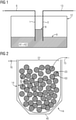
- liquid and non-crosslinked reactive resins are electrically insulating liquids which usually have an electric dipole character, but their value depends on the molecular chain length and nature. It is known that electrically insulating liquids are sucked into an electric field by capillary forces. As in the experiment- see figure 1 - adjusted with the help of a simple plate capacitor, a considerably higher liquid level is generated between the plates than outside the electric field generated by the plates.
- FIG 1 the corresponding experiment is shown schematically, in which this simplest construction of a capacitor is shown in a trough with a reactive resin "K1+K2" as the liquid dielectric.
- the resin basin instead of the trough there is the resin basin and instead of the two plates the winding on the one hand and the body carrying the winding on the other hand are used. These are connected in opposite polarity when they come into contact with the liquid reactive resin.
- This is - as a cross-sectional view into a slot filled with winding - in figure 2 shown. This creates the desired effect that electrostatic capillary forces develop, which push the reactive resin into the inaccessible cavities and/or cracks suck, so that the most complete impregnation of the winding in the slots takes place.
- Liquid, non-crosslinked reactive resins are electrically insulating liquids and, depending on the molecular chain length and composition, have an electric dipole character. It is known from manufacturing measurements that e.g. unsaturated polyester resins have a dielectric constant of approx. 6 to 10 at 50Hz. It is therefore a liquid dielectric.
- liquid i.e. flowable, dielectrics and capacitive structures
- the essence of the invention is the use of the dielectric force to promote and accelerate the flow of the liquid resin into the stator. Accordingly, an electrostatic field is generated between the winding, the slot box and the laminated core or possibly also between different windings, so that the capacitor effect arises.
- the rolling laminated core of the stator is brought to voltage, i.e. to a high potential to earth, by means of a sliding contact.
- the drawn-in windings which are electrically insulated from the laminated core primarily by wire enamel and secondarily by the slot boxes, serve as open earth with so-called floating potential.
- This creates a capacitive structure between the winding and the laminated core of the stator can be realized in such a way that a radial electric field is generated from the filled slot in the direction of the laminated core of the stator, i.e. in particular in such a way that the flow area of the liquid reactive resin is enclosed.
- the electric field generated causes an electrostatic capillary force, which pulls the liquid reactive resin into the otherwise air-filled groove areas.
- a “laminated stator core” in particular is referred to as “body carrying multi-layer windings”.
- a body is usually and according to the present invention made of electrically conductive material, for example sheet metal, iron, etc.
- the body preferably has grooves into which the primarily insulated wires are drawn as a winding.
- This winding is then - for example inside the so-called slot box made of surface insulating material, e.g. folded paper etc. - electrically insulated in the slot by complete encapsulation with impregnating agent.
- This second isolation - around which the invention revolves - is also called secondary isolation.
- the quality of the secondary insulation depends largely on the complete filling of the slots filled with winding with impregnating agent. Air inclusions and/or pores are particularly damaging and the aim of the invention is to avoid air inclusions in the secondary insulation as completely as possible. This is why, for example, the slot and winding are connected in opposite polarity before they are immersed in a resin tank.
- Winding refers to conductors in the form of wires, which are drawn into the slots of a laminated stator core, for example in the form of so-called “random windings” and/or arranged as individual wires or in bundles, each provided with primary insulation.
- the winding comprises wires, such as copper wires, which are already primarily insulated from one another, with wire enamel, for example, representing a typical primary insulation.
- the body carrying the windings is immersed at room temperature in the multi-component resin system or sprinkled with the multi-component resin system or sprayed with the multi-component resin system.
- the body is advantageously a motor or generator or a transformer.
- the motor/generator advantageously has a rotor and a stator.
- the body can also be a stator or a rotor.
- the body carrying the windings is immersed in the multi-component resin system at an ambient temperature of 15 to 25° C., in particular 20 to 23° C., or is sprinkled with the multi-component resin system or sprayed with the multi-component resin system.
- the body carrying the windings is preheated to a temperature of 30 to 80°C, in particular 30 to 60°C.
- the body carrying the windings is preferably inductively preheated to a temperature of 30 to 80°C, in particular 30 to 60°C.
- the body carrying the windings has a defined temperature at the start of the impregnation process, independent of the ambient temperature, and then cools down.
- the multi-component resin system has at least two components, a first component being a resin and a second component being a hardener.
- the first component in particular a resin, preferably has a viscosity of 2000 to 2500 mPa s at an ambient temperature of 25°C and a density of 1.13 to 1.17 g/ml at an ambient temperature of 20 °C
- the second component in particular a hardener, preferably has a viscosity of 40 to 60 mPas, in particular 50 mPas, at an ambient temperature of 25° C. and a density of 0.98 to 1.00 g/ml at a ambient temperature of 20°C.
- a parts by weight mixing ratio is advantageously 100 parts resin to 20 parts hardener.
- a good parts by volume mix ratio is 100 parts resin to 23 parts hardener.
- a pot life at room temperature for 100 g of the mixed material is advantageously between 20 and 40 minutes, preferably 30 minutes.
- the first component in particular a resin, preferably has a viscosity of 2400 to 2600 mPas, 2500 mPas at an ambient temperature of 25°C and a specific gravity of 1.13 to 1.17 g /cm 3 , in particular 1.15 g/cm 3 .
- the second component in particular a hardener, preferably has a viscosity of 200 to 200 mPa s, 300 mPa s at an ambient temperature of 25°C and a specific weight of 1.00 to 1.04 g/cm 3 , in particular 1.02 g/cm 3 .
- a parts-by-weight mix ratio is advantageously 5 parts resin to 1 part hardener.
- a good parts by volume mix ratio is 4.3 parts resin to 1 part hardener.
- the mixed material preferably has a viscosity of 1550-1750 mPa ⁇ s, 1650 mPa ⁇ s at an ambient temperature of 25°C and a specific gravity of 1.11-1.15 g/cm 3 , in particular 1.13 g / cm3 .
- a gel time at 25° C. is advantageously between 25 and 45 minutes, preferably 35 minutes.
- the multi-component resin system is preferably highly reactive.
- the multi-component resin system is preferably a 2K resin system, optionally with other customary additives.
- the second component has a viscosity of 40 to 300 mPa ⁇ s at an ambient temperature of 25°C.
- the resin is an epoxy or a silicone resin
- the hardener being an amine-based hardener
- the amine-based hardener has the advantage that curing can take place at room temperature, also known as cold curing.
- Epoxy resin for example, is advantageous because of its pronounced mechanical properties and only results in a small change in volume during curing.
- epoxy resin does not contain any solvents and has a VOC ⁇ 1% (volatile organic compounds, VOC for short), i.e. less than 1% by weight of the entire material evaporates during the curing process.
- the body rotates about an axis when the body is immersed in a multi-component resin system or is sprinkled with the multi-component resin system or is sprayed with the multi-component resin system.
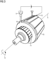
- the body is on a rolling station - see figure 3 .
- the first component and the second component are conveyed separately from one another, with the first component and the second component being mixed immediately before dipping or before sprinkling or before spraying to form the multi-component resin system.
- the reactive resin is formed by mixing the two resin components K1 and K2.
- the rotation of the body prevents the resin system, in particular the resin, from dripping off.
- the resin is drawn into the winding or the slots by existing capillary forces and gels there within a few minutes.
- a drip-free state should be achieved after a maximum of 20 minutes.
- the body can be removed from the rolling station and processed further without having to harden and/or cool down for a long time.
- the multi-component resin system has a viscosity of 300 mPa ⁇ s at 25.degree.
- This viscosity describes an initial viscosity at 25°C. Since the body has been heated to 30 to 80°C, especially 30 to 60°C, the actual viscosity is lower.
- the multi-component resin system has a viscosity of 15,000 mPa ⁇ s after a period of 20 to 30 minutes after it has hit the body.
- the multi-component resin system for sprinkling is formed as a jet with a dosage of between 0.2 ml/s and 2 ml/s.
- the dosage mentioned is advantageous because it allows the resin system to be optimally promoted.
- the dosage mentioned is also advantageous since the resin system is drawn into the winding by capillary forces.
- the laminated core of the stator on the one hand and the winding on the other hand are each connected to opposite-pole voltage via DC voltage, whereby the capillary forces that are already present are supported by electrostatic capillary forces, so that the slot is filled as completely as possible with impregnating agent during the impregnation process.
- the multi-component resin system is at least 95%, preferably at least 97%, hardened.
- the multi-component resin system preferably cures without the active input of heat.
- the multi-component resin system is preferably at least 97% cured after 24 hours.
- figure 1 shows the principle of the generation of electrostatic capillary forces in a liquid two-component resin mixture.
- FIG 1 a resin basin 17 is shown, which is filled with the reactive resin "K1+K2" up to the liquid level 8 or 9, respectively.
- Two capacitor plates 1 and 3 are immersed in the resin basin 17 and are electrically connected with opposite poles via the two connections 6 and 7 .
- a capacitor is formed between the two plates 1 and 3, which sucks the reactive resin "K1 + K2", which is a liquid dielectric, between them up to the liquid level 8 by electrostatic capillary forces against gravity.
- the rest of the resin basin 17 is only at a lower level, up to the liquid level 9, filled.
- the reactive resin K1+K2 is drawn between the capacitor plates 1 and 3 against its own gravity, allowing the capacitor to physically maximize its own stored energy.
- the rising height 8 of the reactive resin K1+K2 results from the force imbalance of the dielectric force, which is greater than the inherent weight of the liquid with a density of approximately 1 g/cm 3 , for example.
- FIG 2 1 shows an embodiment of the invention in which this principle is realized by simple clamp connections 16 and 15 during the impregnation process.
- a filled slot 30 in the stator core 14 a section of a stator core 14, corresponding to the outermost shell 14, which is connected to a positive pole (+) via a terminal 16, for example.
- the slot box 30 filled with windings, which is connected to a negative pole (-) via a further terminal 15 .
- the stator core 14 on the one hand and the filled slot box 30 on the other hand are each connected to potential with opposite poles via the connections 16 and 15 .
- connections 16 and 15 can be implemented here via terminals, but also via any other electrical contacts. Can be seen in figure 2 nor the round cross-sections of the conductors 20 of a winding 22 located in the groove box 30, which comprises copper wires 20 surrounded by primary insulation 50.
- the desired capacitor structure takes place here between the conductors of the winding, which are connected via 15 - shown in simplified form via the groove box 30 in the figure - on the one hand and the laminated core 14, which is connected via 16, on the other hand.
- DC voltage is preferably applied via the electrical contacts 15, 16, so that the field strength in the area of the slot base 30, e.g. from the copper winding 22 to the iron of the stator core 14, is for example 1000 V/mm or more.
- the distance between the copper 20 and the iron/sheet metal 14 of the laminated stator core 14 is given by the slot box 30 and an air gap.
- the distance amounts to 200 ⁇ m to 700 ⁇ m, in particular 300 ⁇ m to 500 ⁇ m and in larger machines up to 1 mm.
- a minimum voltage of 300V, in particular 500V is required to generate sufficient electrostatic capillary force, which sucks the reactive resin into the cracks and air gaps during impregnation.
- the level of stress required can vary, for example it also depends on the flow behavior of the reactive resin in the resin basin 17 (in figure 2 not shown for the sake of simplicity), in particular on its individual viscosity, which in turn depends on the two components K1 and K2, on the temperature and/or the degree of crosslinking.
- voltages from 1 to 3 kV/mm up to 4 kV/mm are used. There are upper limits to the voltage - for example due to the occurrence of partial discharges.
- FIG. 1 shows a dynamo-electric rotary machine 12 during the impregnation process.
- a further embodiment of the invention is thereby shown, through which a capacitor structure can also be implemented here where simple electrical contacting of the wires of the winding within the slot box by means of terminals is not possible.
- a sliding contact 72 is realized, for example.
- the figure 3 shows a stator 70 and a rotor 71.
- the multi-component reactive resin 10 comprising, for example, K1 and K2
- the stator 70 rotates in the direction of rotation R about the axis A.
- the brushes 72 contact the stator core 70 during rotation and impregnation.
- the copper winding itself then serves as the opposite pole.
- the electric field generated in this way causes a force that pulls the liquid reactive resin into the otherwise air-filled groove areas. This acts in addition to the capillary forces acting here during the rolling impregnation, both forces add up to a resulting total force that pulls the liquid resin through the groove.
- the flow rate of the liquid reactive resin is accelerated by the additional force created by generating a capacitor potential - referred to here as electrostatic capillary force - which means that the cycle time during impregnation, for example when dripping, can be reduced.
- electrostatic capillary force - which means that the cycle time during impregnation, for example when dripping, can be reduced.
- the invention opens up a possibility of increasing the flow rate of a reactive resin during impregnation without adversely affecting the viscosity, the toxicity and/or the crosslinking by increasing the temperature and/or the volatility of the overall system by increasing the pressure through chemical additives. Rather, precisely the properties of the system, electrical conductivity of the surrounding housing and dielectricity of the reactive resin are used profitably here in terms of the impregnation process, without having to accept any disadvantages in terms of production technology.
Abstract
Die Erfindung betrifft eine Vorrichtung und ein Verfahren zur Isolation eines ein- oder mehrlagige Wicklungen tragenden Körpers einer elektrischen Maschine, sowie eine elektrische Maschine mit einer derartigen Isolation. Die Erfindung eröffnet erstmals eine Möglichkeit zur Erhöhung der Fließgeschwindigkeit eines Reaktivharzes während des Imprägnierung, ohne durch chemische Zusätze die Viskosität, die Toxizität und/oder durch Temperaturerhöhung die Vernetzung und/oder durch Druckerhöhung die Volatilität des Gesamtsystems nachteilig zu beeinflussen. Vielmehr werden genau die Eigenschaften des Systems, elektrische Leitfähigkeit der umgebenden Gehäuse und Dielektrizität des Reaktivharzes hier gewinnbringend eingesetzt, ohne fertigungstechnische Nachteile dabei in Kauf nehmen zu müssen.The invention relates to a device and a method for insulating a body of an electrical machine that carries single-layer or multi-layer windings, and an electrical machine with such insulation. The invention opens up a possibility for the first time to increase the flow rate of a reactive resin during impregnation without adversely affecting the viscosity, the toxicity and/or the crosslinking by increasing the temperature and/or the volatility of the overall system by increasing the pressure. Rather, precisely the properties of the system, the electrical conductivity of the surrounding housing and the dielectricity of the reactive resin are used profitably here without having to accept any production-related disadvantages.
Description
Die Erfindung betrifft eine Vorrichtung und ein Verfahren zur Isolation eines ein- oder mehrlagige Wicklungen tragenden Körpers einer elektrischen Maschine, sowie eine elektrische Maschine mit einer derartigen Isolation.The invention relates to a device and a method for insulating a body of an electrical machine that carries single-layer or multi-layer windings, and an electrical machine with such insulation.
Elektrische Maschinen, wie Elektromotoren werden mittels gewickelten Rund-Lackdrähten hergestellt, welche nach dem Wickelprozess in das Statorblechpaket eingezogen werden. Der Drahtlack entspricht im Anwendungsbereich der Niederspannungsmotoren, z.B. bis 1kV, der Hauptisolation. Nichtsdestotrotz wird zur weiteren mechanischen Verfestigung sowie zur Passivierung vor äußeren Einflüssen üblicherweise eine weitere Imprägnierung, respektive ein Verguss, durchgeführt.Electrical machines, such as electric motors, are manufactured using wound round enameled wires, which are drawn into the stator core after the winding process. The wire enamel corresponds to the main insulation in the application area of low-voltage motors, e.g. up to 1kV. Nevertheless, further impregnation or casting is usually carried out for further mechanical strengthening and for passivation against external influences.
Eine Herstellung elektrischer Maschinen, beispielsweise Motoren, gelingt meist mit mehreren Fertigungsschritten. Ein Stator wird z. B. nach einem Einziehen von Wicklungen und einem Einbringen von Phasentrennern, Nutisolation und Nutverschluss einem Imprägnierverfahren unterzogen, welches herkömmlicherweise mittels eines heißhärtenden Imprägnierharzes bewerkstelligt wird.A production of electrical machines, such as motors, usually succeeds with several production steps. A stator is z. B. subjected to an impregnation process after drawing in windings and introducing phase separators, slot insulation and slot closure, which is conventionally accomplished by means of a heat-curing impregnating resin.
Insbesondere im Bereich kleinerer Motoren wird häufig ein Imprägnierverfahren angewendet, bei welchem der Motor durch ein Harz aufweisendes Becken, auch Harzbecken genannt, gezogen wird. Kleinere Motoren sind hierbei beispielsweise Motoren mit einer Achshöhe 63 bis hin zu einer Achshöhe 160, wobei die Achshöhe das Maß vom Motorstandfuß bis zur Mitte einer Rotationsachse in mm ist.Particularly in the area of smaller motors, an impregnation process is often used, in which the motor is pulled through a resin-containing basin, also called a resin basin. Smaller motors are here, for example, motors with an axle height of 63 up to an axle height of 160, the axle height being the dimension from the motor base to the center of an axis of rotation in mm.
Fertigungstechnisch ist die Imprägnierung oftmals ein Nadelöhr, da es sich prozessbedingt um einen aufwändigen Vorgang handelt, in dem flüssiges Reaktivharz, z.B. Epoxyharz und/oder Polyesterharz in das Statorblechpaket eingebracht wird. Dies geschieht beispielsweise durch Tauchen, Tauchrollieren und/oder Träufeln.In terms of production technology, impregnation is often a bottleneck, as it is a complex process due to the process is, in which liquid reactive resin, such as epoxy resin and / or polyester resin is introduced into the stator core. This is done, for example, by dipping, dip rolling and/or trickling.
Regelmäßig ist dabei die größte Herausforderung ein Imprägniermittel so zu wählen, das den isolationstechnischen Anforderungen genügt, aber auch innerhalb einer möglichst kurzen Verweilzeit einerseits als dünnflüssiges Imprägniermittel gasfrei und ohne Porenbildung in die Ritzen, und Falten der Wicklung einfließt und andererseits dort beim Übergang zum nächsten Prozessschritt - beispielsweise beim Herausholen des Statorblechpakets aus dem Harzbecken - in der Wicklung gehalten wird, also idealerweise wenig oder gar nicht aus der Wicklung wieder heraus fließt.The greatest challenge is usually to select an impregnating agent that meets the technical insulation requirements, but also flows within the shortest possible residence time as a gas-free, low-viscosity impregnating agent and without pore formation in the cracks and folds of the winding and on the other hand there during the transition to the next process step - for example when removing the stator core from the resin tank - is held in the winding, so ideally little or no flow out of the winding again.
Nach dem Stand der Technik wird dazu ein Beschleuniger, respektive Katalysator der die Polymerisation des Imprägniermittels in Gang setzt, so gewählt, dass das Imprägniermittel zunächst noch dünnflüssig - also niedrig viskos - vorliegt, in alle Ritzen der Wicklung einfließt und dann aber unter den Bedingungen der Imprägnierung schnell polymerisiert und zumindest oberflächlich soweit angeliert, dass das Imprägniermittel in der Wicklung hängen bleibt, insbesondere auch gegen die Schwerkraft beim Herausholen des Statorblechpakets aus dem Harzbecken.According to the state of the art, an accelerator or catalyst that initiates the polymerization of the impregnating agent is selected in such a way that the impregnating agent is initially still thin - i.e. low-viscous - flows into all the cracks in the winding and then, under the conditions of the Impregnation polymerized quickly and gelled at least superficially to the extent that the impregnating agent gets caught in the winding, especially against gravity when removing the stator core from the resin basin.
Zwar ist aus der
Dabei ist insbesondere bevorzugt, dass durch die Rotation des Körpers ein Abtropfen des Harzsystems verhindert wird. Durch vorhandene Kapillarkräfte wird das Harz in die Nuten gezogen und geliert dort innerhalb weniger Minuten. Eine Tropffreiheit soll nach max. 20 min erreicht sein. Der Körper kann ohne lange aushärten und/oder abkühlen zu müssen, von der Rollier-Station entnommen werden und weiterbearbeitet werden.It is particularly preferred that the rotation of the body prevents the resin system from dripping off. The resin is drawn into the grooves by capillary forces and gels there within a few minutes. A drip-free state should be achieved after a maximum of 20 minutes. The body can be removed from the rolling station and processed further without having to harden and/or cool down for a long time.
Nachteilig an dieser Ausführungsform ist jedoch, dass bei dem Verfahren niedrige Temperaturen vorliegen, so dass das Reaktivharz, also das Harz bei dem die beiden Komponenten schon gemischt sind, relativ hohe Viskosität hat und dementsprechend das Fließverhalten, insbesondere in horizontaler Richtung in die teilweise mehrere 100 mm langen Nuten, durch Kapillarkräfte gehemmt ist.The disadvantage of this embodiment, however, is that the process is carried out at low temperatures, so that the reactive resin, i.e. the resin in which the two components are already mixed, has a relatively high viscosity and accordingly the flow behavior, especially in the horizontal direction, can sometimes be several 100 mm long grooves, is inhibited by capillary forces.
Die, vergleichsweise zu anderen Verfahren mit höheren Temperaturen, geringeren Kapillarkräfte verursachen längere Prozesszeiten, also eine längere Zeit, bis eine definierte Menge Reaktivharz auf das Statorblechpaket mit der Wicklung appliziert ist, so dass die Masse tropffrei in das rollierende Statorblechpaket durch Kapillarkräfte gesogen wird.The lower capillary forces compared to other processes with higher temperatures cause longer process times, i.e. a longer time until a defined amount of reactive resin is applied to the stator core with the winding, so that the mass is sucked drip-free into the rolling stator core by capillary forces.
Aufgabe der vorliegenden Erfindung ist daher, eine Vorrichtung und ein Verfahren anzugeben, mit dem diese Prozesszeit optimiert werden kann.The object of the present invention is therefore to specify a device and a method with which this process time can be optimized.
Diese Aufgabe wird durch den Gegenstand der vorliegenden Erfindung, wie er in den Ansprüchen, der Figur und der Beschreibung offenbart wird, gelöst.This object is solved by the subject matter of the present invention as disclosed in the claims, the figure and the description.
Lösung der Aufgabe ist dementsprechend eine Vorrichtung zum Imprägnieren, Verfestigen oder Elektroisolieren eines ein- oder mehrlagige Wicklungen tragenden Körpers, wobei Gleichspannung zwischen Wicklung und Körper angelegt ist, so dass der die Wicklungen tragende Körper einerseits und die Wicklungen andererseits wie die beiden Elektroden eines Kondensators fungieren und ein flüssiges Dielektrikum ansaugen. Außerdem ist Gegenstand der vorliegenden Erfindung ein Verfahren zum Imprägnieren einer ein- oder mehrlagige Wicklungen tragenden Körpers einer elektrischen Maschine, wobei der Wicklungen tragende Körper in ein mehrkomponentiges Reaktivharzbecken getaucht wird oder mit dem mehrkomponentigen Reaktivharz beträufelt oder besprüht wird, wobei zwischen den Wicklungen und dem die Wicklungen tragenden Körper während des Imprägnierens eine Gleichspannung derart angelegt wird, dass zumindest 300V/mm, bevorzugt 500V/mm und insbesondere zwischen 500V/mm und 4000V/mm dazwischen liegen.Accordingly, the solution to the problem is a device for impregnating, solidifying or electrically insulating a body carrying single or multi-layer windings, with DC voltage being applied between the winding and the body, so that the body carrying the windings on the one hand and the windings on the other hand act like the two electrodes of a capacitor and suck in a liquid dielectric. In addition, the subject of the present invention is a method for impregnating a body of an electrical machine which carries single or multi-layer windings, the body carrying the windings being immersed in a multi-component reactive resin basin or sprinkled or sprayed with the multi-component reactive resin, with the windings and the A DC voltage is applied to the body carrying windings during the impregnation in such a way that at least 300V/mm, preferably 500V/mm and in particular between 500V/mm and 4000V/mm lie in between.
Allgemeine Erkenntnis der Erfindung ist es, dass flüssige und unvernetzte Reaktivharze elektrisch isolierende Flüssigkeiten sind, die regelmäßig, aber dem Wert nach abhängig von molekularer Kettenlänge und Beschaffenheit, elektrischen Dipolcharakter besitzen. Bekannt ist, dass elektrisch isolierende Flüssigkeiten durch Kapillarkräfte in ein elektrisches Feld hineingesaugt werden. Wie im Versuch- siehe
In
Als Reaktivharz sind alle Arten von fertig gemischten Imprägniermittel einsetzbar, die in flüssigem Zustand eine höhere Dielektrikumszahl haben als Luft.All types of ready-mixed impregnating agents that have a higher dielectric constant than air in the liquid state can be used as reactive resin.
Flüssige unvernetzte Reaktivharze sind elektrisch isolierende Flüssigkeiten und besitzen, je nach molekularer Kettenlänge und Beschaffenheit, elektrischen Dipolcharakter. Aus fertigungstechnischen Messung ist bekannt, dass z.B. ungesättigte Polyesterharze bei 50Hz eine Dielektrizitätszahl von ca. 6 bis 10 besitzen. Somit handelt es sich dabei um ein flüssiges Dielektrikum.Liquid, non-crosslinked reactive resins are electrically insulating liquids and, depending on the molecular chain length and composition, have an electric dipole character. It is known from manufacturing measurements that e.g. unsaturated polyester resins have a dielectric constant of approx. 6 to 10 at 50Hz. It is therefore a liquid dielectric.
Ein Effekt von flüssigen, also fließfähigen, Dielektrika sowie kapazitiven Aufbauten ist eine Fließkraft in der Flüssigkeit, welche versucht, das flüssige Dielektrikum in einen Kondensator zu saugen, sobald dieser geladen wird und der Kondensatorzwischenraum mit einem Dielektrikum niedriger Dielektrizitätszahl gefüllt ist, wie z.B. mit Luft, deren Dielektrizitätszahl = 1 ist.One effect of liquid, i.e. flowable, dielectrics and capacitive structures is a flow force in the liquid, which tries to suck the liquid dielectric into a capacitor as soon as it is charged and the space between the capacitors is filled with a dielectric with a low dielectric constant, such as air , whose dielectric constant = 1.
Der Kern der Erfindung ist die Nutzung der dielektrischen Kraft, um das Einfließen des Flüssigharzes in den Stator zu begünstigen und beschleunigen. Es wird demgemäß zwischen der Wicklung, dem Nutkasten und dem Blechpaket oder gegebenenfalls auch zwischen verschiedenen Wicklungen, ein elektrostatisches Feld erzeugt werde, so dass der Kondensatoreffekt entsteht.The essence of the invention is the use of the dielectric force to promote and accelerate the flow of the liquid resin into the stator. Accordingly, an electrostatic field is generated between the winding, the slot box and the laminated core or possibly also between different windings, so that the capacitor effect arises.
Beispielsweise wird bei der rollierenden Imprägnierung mittels eines Schleifkontaktes das rollierende Statorblechpaket auf Spannung, also auf hohes Potential zur Erde, gebracht. Dabei dienen die eingezogenen Wicklungen, welche primär durch Drahtlack und sekundär durch die Nutkästen vom Blechpaket elektrisch isoliert sind, als offene Erde mit so genanntem schwebendem Potential. Dadurch ist ein kapazitiver Aufbau zwischen Wicklung und Statorblechpaket realisierbar, dergestalt, dass jeweils ein radiales elektrisches Feld von der gefüllten Nut aus in Richtung Statorblechpaket erzeugt wird, also insbesondere so, dass der Fließbereich des flüssigen Reaktivharzes eingeschlossen ist.For example, in the case of rolling impregnation, the rolling laminated core of the stator is brought to voltage, i.e. to a high potential to earth, by means of a sliding contact. The drawn-in windings, which are electrically insulated from the laminated core primarily by wire enamel and secondarily by the slot boxes, serve as open earth with so-called floating potential. This creates a capacitive structure between the winding and the laminated core of the stator can be realized in such a way that a radial electric field is generated from the filled slot in the direction of the laminated core of the stator, i.e. in particular in such a way that the flow area of the liquid reactive resin is enclosed.
Das erzeugte elektrische Feld bewirkt eine elektrostatische Kapillarkraft, welche das flüssige Reaktivharz in die sonst mit Luft gefüllten Nutbereiche zieht.The electric field generated causes an electrostatic capillary force, which pulls the liquid reactive resin into the otherwise air-filled groove areas.
Als "mehrlagige Wicklungen tragender Körper" wird vorliegend insbesondere ein Statorblechpaket bezeichnet. Ein derartiger Körper ist in der Regel und gemäß der vorliegenden Erfindung aus elektrisch leitfähigem Material, beispielsweise aus Blech, Eisen etc. Vorzugsweise weist der Körper Nuten auf, in die die primär isolierten Drähte als Wicklung eingezogen werden. Diese Wicklung wird dann -beispielsweise innerhalb des so genannten Nutkasten aus Flächenisolierstoff, z.B. gefalztem Papier etc., - in der Nut durch komplett-Verguss mit Imprägniermittel elektrisch isoliert. Diese zweite Isolation - um die sich die Erfindung dreht - nennt man auch sekundär-Isolation.In the present case, a “laminated stator core” in particular is referred to as “body carrying multi-layer windings”. Such a body is usually and according to the present invention made of electrically conductive material, for example sheet metal, iron, etc. The body preferably has grooves into which the primarily insulated wires are drawn as a winding. This winding is then - for example inside the so-called slot box made of surface insulating material, e.g. folded paper etc. - electrically insulated in the slot by complete encapsulation with impregnating agent. This second isolation - around which the invention revolves - is also called secondary isolation.
Die Güte der sekundär-Isolation hängt maßgeblich von der vollständigen Füllung der mit Wicklung gefüllten Nuten mit Imprägniermittel ab. Lufteinschlüsse und/oder Poren sind dabei besonders schadhaft und Ziel der Erfindung ist es, Lufteinschlüsse in der sekundär-Isolation möglichst vollständig zu vermeiden. Deshalb werden beispielsweise Nut und Wicklung gegenpolig angeschlossen, bevor sie in ein Harzbecken eingetaucht werden.The quality of the secondary insulation depends largely on the complete filling of the slots filled with winding with impregnating agent. Air inclusions and/or pores are particularly damaging and the aim of the invention is to avoid air inclusions in the secondary insulation as completely as possible. This is why, for example, the slot and winding are connected in opposite polarity before they are immersed in a resin tank.
Bei einer rotierenden oder rollierenden Anlage ist ein einfaches Anschließen nicht möglich, deshalb wird hier vorgeschlagen, beispielsweise mit einem Kohlebesen, - siehe
Als "Wicklung" werden Leiter in Form von Drähten bezeichnet, die beispielsweise in Form von so genannten "wilden Wicklungen" und/oder geordnet als Einzeldrähte oder in Bündeln, jeweils mit einer Primärisolation versehen, in die Nuten eines Statorblechpakets eingezogen werden."Winding" refers to conductors in the form of wires, which are drawn into the slots of a laminated stator core, for example in the form of so-called "random windings" and/or arranged as individual wires or in bundles, each provided with primary insulation.
Die Wicklung umfasst Drähte wie beispielsweise Kupfer-Drähte in gegeneinander bereits primär isolierter Form, wobei beispielsweise ein Drahtlack eine übliche Primärisolation darstellt.The winding comprises wires, such as copper wires, which are already primarily insulated from one another, with wire enamel, for example, representing a typical primary insulation.
In einer vorteilhaften Ausführungsform der Erfindung wird der die Wicklungen tragende Körper bei Raumtemperatur in das mehrkomponentige Harzsystem getaucht oder mit dem mehrkomponentigen Harzsystem beträufelt oder mit dem mehrkomponentigen Harzsystem besprüht.In an advantageous embodiment of the invention, the body carrying the windings is immersed at room temperature in the multi-component resin system or sprinkled with the multi-component resin system or sprayed with the multi-component resin system.
Der Körper ist vorteilhaft ein Motor oder Generator oder ein Transformator. Der Motor/Generator weist vorteilhaft einen Rotor und einen Stator auf.The body is advantageously a motor or generator or a transformer. The motor/generator advantageously has a rotor and a stator.
Der Körper kann auch ein Stator oder ein Rotor sein.The body can also be a stator or a rotor.
In einer vorteilhaften Ausführungsform der Erfindung wird der die Wicklungen tragende Körper bei einer Umgebungstemperatur von 15 bis 25°C, insbesondere 20 bis 23°C, in das mehrkomponentige Harzsystem getaucht oder mit dem mehrkomponentigen Harzsystem beträufelt oder mit dem mehrkomponentigen Harzsystem besprüht.In an advantageous embodiment of the invention, the body carrying the windings is immersed in the multi-component resin system at an ambient temperature of 15 to 25° C., in particular 20 to 23° C., or is sprinkled with the multi-component resin system or sprayed with the multi-component resin system.
In einer weiteren vorteilhaften Ausführungsform der Erfindung wird der die Wicklungen tragende Körper auf eine Temperatur von 30 bis 80°C, insbesondere 30 bis 60°C, vorgewärmt. Vorzugsweise wird der die Wicklungen tragende Körper auf eine Temperatur von 30 bis 80°C, insbesondere 30 bis 60°C, induktiv vorgewärmt.In a further advantageous embodiment of the invention, the body carrying the windings is preheated to a temperature of 30 to 80°C, in particular 30 to 60°C. The body carrying the windings is preferably inductively preheated to a temperature of 30 to 80°C, in particular 30 to 60°C.
Dies hat den Vorteil, dass unterschiedliche Umgebungstemperaturen, z. B. im Sommer oder Winter, keinen Einfluss auf das Imprägnieren, Verfestigen oder Elektroisolieren haben.This has the advantage that different ambient temperatures, e.g. B. in summer or winter, have no influence on the impregnation, solidification or electrical insulation.
Der die Wicklungen tragende Körper weist umgebungstemperaturunabhängig zu Beginn des Verfahrens zur Imprägnierung eine definierte Temperatur auf und kühlt dann ab.The body carrying the windings has a defined temperature at the start of the impregnation process, independent of the ambient temperature, and then cools down.
In einer weiteren vorteilhaften Ausführungsform der Erfindung weist das mehrkomponentige Harzsystem wenigstens zwei Komponenten auf, wobei eine erste Komponente ein Harz ist, wobei eine zweite Komponente ein Härter ist.In a further advantageous embodiment of the invention, the multi-component resin system has at least two components, a first component being a resin and a second component being a hardener.
Ein erstes Beispiel: Die erste Komponente, insbesondere ein Harz, weist vorzugsweise eine Viskosität von 2000 bis 2500 mPa·s bei einer Umgebungstemperatur von 25°C auf und eine Dichte von 1,13 bis 1,17 g/ml bei einer Umgebungstemperatur von 20°C. Die zweite Komponente, insbesondere ein Härter, weist vorzugsweise eine Viskosität von 40 bis 60 mPa·s, insbesondere 50 mPa·s, bei einer Umgebungstemperatur von 25°C auf und eine Dichte von 0,98 bis 1,00 g/ml bei einer Umgebungstemperatur von 20°C. Ein Teile-nach-Gewicht-Mischungsverhältnis liegt vorteilhaft bei 100 Teilen Harz zu 20 Teilen Härter. Ein Teile-nach-Volumen-Mischungsverhältnis liegt vorteilhaft bei 100 Teilen Harz zu 23 Teilen Härter. Eine Topfzeit bei Raumtemperatur für 100 g des gemischten Materials liegt vorteilhaft zwischen 20 und 40 min, vorzugsweise 30 min.A first example: The first component, in particular a resin, preferably has a viscosity of 2000 to 2500 mPa s at an ambient temperature of 25°C and a density of 1.13 to 1.17 g/ml at an ambient temperature of 20 °C The second component, in particular a hardener, preferably has a viscosity of 40 to 60 mPas, in particular 50 mPas, at an ambient temperature of 25° C. and a density of 0.98 to 1.00 g/ml at a ambient temperature of 20°C. A parts by weight mixing ratio is advantageously 100 parts resin to 20 parts hardener. A good parts by volume mix ratio is 100 parts resin to 23 parts hardener. A pot life at room temperature for 100 g of the mixed material is advantageously between 20 and 40 minutes, preferably 30 minutes.
Ein zweites Beispiel: Die erste Komponente, insbesondere ein Harz, weist vorzugsweise eine Viskosität von 2400 bis 2600 mPa·s, 2500 mPa·s, bei einer Umgebungstemperatur von 25°C auf und ein spezifisches Gewicht von 1,13 bis 1,17 g/cm3, insbesondere 1,15 g/cm3. Die zweite Komponente, insbesondere ein Härter, weist vorzugsweise eine Viskosität von 200 bis 200 mPa·s, 300 mPa·s, bei einer Umgebungstemperatur von 25°C auf und ein spezifisches Gewicht von 1,00 bis 1,04 g/cm3, insbesondere 1,02 g/cm3. Ein Teile-nach-Gewicht-Mischungsverhältnis liegt vorteilhaft bei 5 Teilen Harz zu 1 Teil Härter. Ein Teile-nach-Volumen-Mischungsverhältnis liegt vorteilhaft bei 4,3 Teilen Harz zu 1 Teil Härter. Das gemischte Material weist vorzugsweise eine Viskosität von 1550 bis 1750 mPa·s, 1650 mPa·s, bei einer Umgebungstemperatur von 25°C auf und ein spezifisches Gewicht von 1,11 bis 1,15 g/cm3, insbesondere 1,13 g/cm3. Eine Gelierzeit bei 25°C liegt vorteilhaft zwischen 25 und 45 min, vorzugsweise 35 min.A second example: The first component, in particular a resin, preferably has a viscosity of 2400 to 2600 mPas, 2500 mPas at an ambient temperature of 25°C and a specific gravity of 1.13 to 1.17 g /cm 3 , in particular 1.15 g/cm 3 . The second component, in particular a hardener, preferably has a viscosity of 200 to 200 mPa s, 300 mPa s at an ambient temperature of 25°C and a specific weight of 1.00 to 1.04 g/cm 3 , in particular 1.02 g/cm 3 . A parts-by-weight mix ratio is advantageously 5 parts resin to 1 part hardener. A good parts by volume mix ratio is 4.3 parts resin to 1 part hardener. The mixed material preferably has a viscosity of 1550-1750 mPa·s, 1650 mPa·s at an ambient temperature of 25°C and a specific gravity of 1.11-1.15 g/cm 3 , in particular 1.13 g / cm3 . A gel time at 25° C. is advantageously between 25 and 45 minutes, preferably 35 minutes.
Das mehrkomponentige Harzsystem ist vorzugsweise hochreaktiv. Das mehrkomponentige Harzsystem ist vorzugsweise ein 2K-Harzsystem, gegebenenfalls mit weiteren üblichen Additiven.The multi-component resin system is preferably highly reactive. The multi-component resin system is preferably a 2K resin system, optionally with other customary additives.
Vorzugsweise weist die zweite Komponente eine Viskosität von 40 bis 300 mPa·s bei einer Umgebungstemperatur von 25°C auf.Preferably, the second component has a viscosity of 40 to 300 mPa·s at an ambient temperature of 25°C.
In einer weiteren vorteilhaften Ausführungsform der Erfindung ist das Harz ein Epoxid- oder ein Silikonharz, wobei der Härter ein Härter auf Aminbasis ist.In a further advantageous embodiment of the invention, the resin is an epoxy or a silicone resin, the hardener being an amine-based hardener.
Der Amin basierte Härter bringt den Vorteil mit sich, dass die Aushärtung bei Zimmertemperatur erfolgen kann, auch Kalthärtung genannt. Beispielsweise Epoxidharz ist aufgrund seiner ausgeprägten mechanischen Eigenschaften vorteilhaft und hat nur eine kleine Volumenänderung während des Aushärtens zur Folge. Epoxidharz beinhaltet vorteilhaft keine Lösemittel und weist ein VOC < 1% auf (volatile organic compounds, kurz VOC), d.h. es dampfen weniger als 1 Gew.-% des gesamten Materials im Laufe des Härtungsvorgangs ab.The amine-based hardener has the advantage that curing can take place at room temperature, also known as cold curing. Epoxy resin, for example, is advantageous because of its pronounced mechanical properties and only results in a small change in volume during curing. Advantageously, epoxy resin does not contain any solvents and has a VOC < 1% (volatile organic compounds, VOC for short), i.e. less than 1% by weight of the entire material evaporates during the curing process.
In einer weiteren vorteilhaften Ausführungsform rotiert der Körper um eine Achse, wenn der Körper in ein mehrkomponentiges Harzsystem getaucht wird oder mit dem mehrkomponentigen Harzsystem beträufelt wird oder mit dem mehrkomponentigen Harzsystem besprüht wird.In a further advantageous embodiment, the body rotates about an axis when the body is immersed in a multi-component resin system or is sprinkled with the multi-component resin system or is sprayed with the multi-component resin system.
Vorteilhaft befindet sich der Körper auf einer Rollier-Station - siehe
In einer weiteren vorteilhaften Ausführungsform der Erfindung werden die erste Komponente und die zweite Komponente getrennt voneinander gefördert, wobei die erste Komponente und die zweite Komponente unmittelbar vor dem Tauchen oder vor dem Beträufeln oder vor dem Besprühen zum mehrkomponentigen Harzsystem vermischt werden. Durch Vermischen der beiden Harzkomponenten K1 und K2 entsteht dabei das Reaktivharz.In a further advantageous embodiment of the invention, the first component and the second component are conveyed separately from one another, with the first component and the second component being mixed immediately before dipping or before sprinkling or before spraying to form the multi-component resin system. The reactive resin is formed by mixing the two resin components K1 and K2.
Unmittelbar bedeutet vorzugsweise: max. 10 min.Immediately preferably means: max. 10 min.
Durch die Rotation des Körpers wird ein Abtropfen des Harzsystems, insbesondere des Harzes, verhindert. Durch vorhandene Kapillarkräfte wird das Harz in die Wicklung, respektive die Nuten gezogen und geliert dort innerhalb weniger Minuten. Eine Tropffreiheit soll nach max. 20 min erreicht sein. Der Körper kann - ohne lange aushärten und/oder abkühlen zu müssen - von der Rollier-Station entnommen werden und weiterbearbeitet werden.The rotation of the body prevents the resin system, in particular the resin, from dripping off. The resin is drawn into the winding or the slots by existing capillary forces and gels there within a few minutes. A drip-free state should be achieved after a maximum of 20 minutes. The body can be removed from the rolling station and processed further without having to harden and/or cool down for a long time.
In einer weiteren vorteilhaften Ausführungsform der Erfindung weist das mehrkomponentige Harzsystem eine Viskosität von 300 mPa·s bei 25°C auf.In a further advantageous embodiment of the invention, the multi-component resin system has a viscosity of 300 mPa·s at 25.degree.
Diese Viskosität beschreibt eine Anfangsviskosität bei 25°C. Da der Körper auf 30 bis 80°C, insbesondere 30 bis 60°C erwärmt wurde, ist die tatsächliche Viskosität geringer.This viscosity describes an initial viscosity at 25°C. Since the body has been heated to 30 to 80°C, especially 30 to 60°C, the actual viscosity is lower.
In einer weiteren vorteilhaften Ausführungsform der Erfindung weist das mehrkomponentige Harzsystem nach einer Zeitspanne von 20 bis 30 min nach dem Auftreffen auf den Körper eine Viskosität von 15000 mPa·s auf.In a further advantageous embodiment of the invention, the multi-component resin system has a viscosity of 15,000 mPa·s after a period of 20 to 30 minutes after it has hit the body.
In einer weiteren vorteilhaften Ausführungsform der Erfindung wird das mehrkomponentige Harzsystem zum Beträufeln als Strahl mit einer Dosierung zwischen 0,2 ml/s und 2 ml/s geformt.In a further advantageous embodiment of the invention, the multi-component resin system for sprinkling is formed as a jet with a dosage of between 0.2 ml/s and 2 ml/s.
Die genannte Dosierung ist vorteilhaft, da dadurch das Harzsystem optimal gefördert werden kann. Die genannte Dosierung ist zudem vorteilhaft, da dadurch das Harzsystem über Kapillarkräfte in die Wicklung gezogen wird. Gemäß der Erfindung wird das Statorblechpaket einerseits und die Wicklung andererseits über Gleichspannung auf jeweils gegenpolige Spannung gelegt, wodurch die sowieso schon herrschenden Kapillarkräfte durch elektrostatische Kapillarkräfte unterstützt werden, damit eine möglichst vollständige Füllung der Nut mit Imprägniermittel während des Verfahrens zur Imprägnierung erzielt wird.The dosage mentioned is advantageous because it allows the resin system to be optimally promoted. The dosage mentioned is also advantageous since the resin system is drawn into the winding by capillary forces. According to the invention, the laminated core of the stator on the one hand and the winding on the other hand are each connected to opposite-pole voltage via DC voltage, whereby the capillary forces that are already present are supported by electrostatic capillary forces, so that the slot is filled as completely as possible with impregnating agent during the impregnation process.
In einer weiteren vorteilhaften Ausführungsform er Erfindung ist das mehrkomponentige Harzsystem bei einer Umgebungstemperatur von 15 bis 25 °C, insbesondere 20 bis 23 °C, nach weniger als 100 h, vorzugsweise weniger als 72 h, zu wenigstens 95%, vorzugsweise wenigstens 97%, ausgehärtet.In a further advantageous embodiment of the invention, at an ambient temperature of 15 to 25° C., in particular 20 to 23° C., after less than 100 h, preferably less than 72 h, the multi-component resin system is at least 95%, preferably at least 97%, hardened.
Das mehrkomponentige Harzsystem härtet vorzugsweise ohne den aktiven Eintrag von Wärme aus.The multi-component resin system preferably cures without the active input of heat.
Bei Raumtemperatur ist das mehrkomponentige Harzsystem vorzugsweise nach 24 h zu min 97% ausgehärtet.At room temperature, the multi-component resin system is preferably at least 97% cured after 24 hours.
Im Folgenden wird die Erfindung noch anhand von 3 Figuren näher erläutert:
-
Figur 1 -
Figur 2 zeigt eine Ausführungsform der Erfindung, bei der das inFigur 1 -
Figur 3 zeigt eine Ausführungsform der Erfindung, bei der das inFigur 1
-
figure 1 shows the principle of generating electrostatic capillary forces in a reactive resin tank. -
figure 2 shows an embodiment of the invention in which thefigure 1 principle shown is applied to a slot filled with winding and -
figure 3 shows an embodiment of the invention in which thefigure 1 principle shown is applied to a rolling stator.
In
Wie gezeigt, wird beim Anlegen der Spannung das Reaktivharz K1+K2 entgegen seiner eigenen Schwerkraft zwischen die Kondensatorplatten 1 und 3 gesogen, so dass der Kondensator seine eigene gespeicherte Energie physikalisch maximieren kann. Die Steighöhe 8 des Reaktivharzes K1+K2 ergibt sich aus dem Kräfteungleichgewicht der dielektrischen Kraft, welche größer ist als die eigene Gewichtskraft der Flüssigkeit mit einer Dichte von ca. 1g/cm3, beispielsweise.As shown, when the voltage is applied, the reactive resin K1+K2 is drawn between the
Die Anschlüsse 16 und 15 können hier über Klemmen, aber auch über beliebige andere elektrische Kontakte realisiert sein. Zu erkennen sind in
Es wird bevorzugt über die elektrischen Kontakte 15, 16 Gleichspannung angelegt, so dass die Feldstärke im Bereich des Nutgrunds 30, also z.B. von der Kupferwicklung 22 zu Eisen des Statorblechpakets 14 beispielsweise 1000V/mm oder mehr beträgt. Der Abstand des Kupfers 20 zum Eisen/Blech 14 des Statorblechpakets 14 ist durch den Nutkasten 30 und einen Luftspalt gegeben. Beispielsweise beläuft sich der Abstand auf 200µm bis 700µm, insbesondere 300µm bis 500µm und bei größeren Maschinen bis zu 1mm. Dann ist jedenfalls eine Mindestspannung von 300V, insbesondere von 500V, zur Erzeugung einer ausreichenden elektrostatischen Kapillarkraft, die das Reaktivharz während der Imprägnierung in die Ritzen und Luftspalte saugt, erforderlich.DC voltage is preferably applied via the
Die erforderliche Höhe der Spannung kann variieren, beispielsweise ist diese auch vom Fließverhalten des Reaktivharzes im Harzbecken 17 (in
Beispielsweise werden Spannungen von 1 bis 3 kV/mm bis zu 4kV/mm eingesetzt. Der Spannung sind nach oben hin - beispielsweise durch Auftreten von Teilentladungen - Grenzen gesetzt.For example, voltages from 1 to 3 kV/mm up to 4 kV/mm are used. There are upper limits to the voltage - for example due to the occurrence of partial discharges.
Die
Dabei wird eine weitere Ausführungsform der Erfindung gezeigt, durch die auch hier, wo eine einfache elektrische Kontaktierung der Drähte der Wicklung innerhalb des Nutkastens mittels Klemmen nicht möglich ist, ein Kondensatoraufbau realisierbar ist. Bei dieser Ausführungsform, die auch aus der noch unveröffentlichten Anmeldung
Die
In der
Die Bürsten 72 kontaktieren das Statorblechpaket 70, während der Rotation und Imprägnierung. Als Gegenpol dient dann die Kupferwicklung an sich.The
Das so erzeugte elektrische Feld bewirkt eine Kraft, die das flüssige Reaktivharz in die sonst mit Luft gefüllten Nutbereiche zieht. Diese wirkt zusätzlich zu den hier bei dem rollierenden Imprägnieren wirkenden Kapillarkräften, beide Kräfte addieren sich zu einer resultierenden Gesamtkraft, welche die Flüssigharze durch die Nut zieht.The electric field generated in this way causes a force that pulls the liquid reactive resin into the otherwise air-filled groove areas. This acts in addition to the capillary forces acting here during the rolling impregnation, both forces add up to a resulting total force that pulls the liquid resin through the groove.
Durch die durch Erzeugen eines Kondensator-Potentials zusätzliche Kraft - hier elektrostatische Kapillarkraft genannt - wird die Fließgeschwindigkeit des flüssigen Reaktivharzes beschleunigt, womit die Taktzeit beim Imprägnieren, beispielsweise beim Beträufeln, reduzierbar ist. Damit wird eine kosteneffizientere, qualitativ höhere und noch besser reproduzierbare Imprägnierung bei einem ansonsten gleichbleibendem Fertigungsaufbau möglich. Bislang war keine Technik verfügbar, mit der die Fließgeschwindigkeit des Reaktivharzes so unbelastend für das restliche System beeinflusst werden konnte.The flow rate of the liquid reactive resin is accelerated by the additional force created by generating a capacitor potential - referred to here as electrostatic capillary force - which means that the cycle time during impregnation, for example when dripping, can be reduced. This enables a more cost-efficient, qualitatively higher and even better reproducible impregnation with an otherwise unchanged production structure. Until now, no technology was available with which the flow rate of the reactive resin could be influenced in such a way that the rest of the system was not affected.
Die Erfindung eröffnet erstmals eine Möglichkeit zur Erhöhung der Fließgeschwindigkeit eines Reaktivharzes während der Imprägnierung, ohne durch chemische Zusätze die Viskosität, die Toxizität und/oder durch Temperaturerhöhung die Vernetzung und/oder durch Druckerhöhung die Volatilität des Gesamtsystems nachteilig zu beeinflussen. Vielmehr werden genau die Eigenschaften des Systems, elektrische Leitfähigkeit der umgebenden Gehäuse und Dielektrizität des Reaktivharzes hier gewinnbringend im Sinne des Imprägnierverfahrens eingesetzt, ohne fertigungstechnische Nachteile dabei in Kauf nehmen zu müssen.For the first time, the invention opens up a possibility of increasing the flow rate of a reactive resin during impregnation without adversely affecting the viscosity, the toxicity and/or the crosslinking by increasing the temperature and/or the volatility of the overall system by increasing the pressure through chemical additives. Rather, precisely the properties of the system, electrical conductivity of the surrounding housing and dielectricity of the reactive resin are used profitably here in terms of the impregnation process, without having to accept any disadvantages in terms of production technology.
Claims (15)
Priority Applications (5)
| Application Number | Priority Date | Filing Date | Title |
|---|---|---|---|
| EP20191514.7A EP3958449A1 (en) | 2020-08-18 | 2020-08-18 | Electric machine and device and method for isolating a body carrying single-layer or multilayer windings |
| US18/042,250 US20240014720A1 (en) | 2020-08-18 | 2021-08-09 | Apparatus and Method for Insulation of a Body Carrying Single-Layer or Multi-Layer Windings, and Electric Machine |
| EP21762399.0A EP4179613A1 (en) | 2020-08-18 | 2021-08-09 | Apparatus and method for insulation of a body carrying single-layer or multi-layer windings, and electric machine |
| CN202180050592.6A CN115867993A (en) | 2020-08-18 | 2021-08-09 | Device and method for insulating a body carrying a single-layer or multi-layer winding, and electric machine |
| PCT/EP2021/072183 WO2022037988A1 (en) | 2020-08-18 | 2021-08-09 | Apparatus and method for insulation of a body carrying single-layer or multi-layer windings, and electric machine |
Applications Claiming Priority (1)
| Application Number | Priority Date | Filing Date | Title |
|---|---|---|---|
| EP20191514.7A EP3958449A1 (en) | 2020-08-18 | 2020-08-18 | Electric machine and device and method for isolating a body carrying single-layer or multilayer windings |
Publications (1)
| Publication Number | Publication Date |
|---|---|
| EP3958449A1 true EP3958449A1 (en) | 2022-02-23 |
Family
ID=72145282
Family Applications (2)
| Application Number | Title | Priority Date | Filing Date |
|---|---|---|---|
| EP20191514.7A Withdrawn EP3958449A1 (en) | 2020-08-18 | 2020-08-18 | Electric machine and device and method for isolating a body carrying single-layer or multilayer windings |
| EP21762399.0A Pending EP4179613A1 (en) | 2020-08-18 | 2021-08-09 | Apparatus and method for insulation of a body carrying single-layer or multi-layer windings, and electric machine |
Family Applications After (1)
| Application Number | Title | Priority Date | Filing Date |
|---|---|---|---|
| EP21762399.0A Pending EP4179613A1 (en) | 2020-08-18 | 2021-08-09 | Apparatus and method for insulation of a body carrying single-layer or multi-layer windings, and electric machine |
Country Status (4)
| Country | Link |
|---|---|
| US (1) | US20240014720A1 (en) |
| EP (2) | EP3958449A1 (en) |
| CN (1) | CN115867993A (en) |
| WO (1) | WO2022037988A1 (en) |
Citations (3)
| Publication number | Priority date | Publication date | Assignee | Title |
|---|---|---|---|---|
| FR2210042A1 (en) * | 1972-12-08 | 1974-07-05 | Gen Electric | Repairing exposed winding surfaces - by dipping in polymer medium and hardening, pref followed by lacquering, eg for stator and rotor windings |
| JPS57132750A (en) * | 1981-02-12 | 1982-08-17 | Toshiba Corp | Manufacture of coil for rotary electric machine |
| JPS63107441A (en) * | 1986-10-24 | 1988-05-12 | Toshiba Corp | Core insulation for rotary electric machine |
-
2020
- 2020-08-18 EP EP20191514.7A patent/EP3958449A1/en not_active Withdrawn
-
2021
- 2021-08-09 CN CN202180050592.6A patent/CN115867993A/en active Pending
- 2021-08-09 EP EP21762399.0A patent/EP4179613A1/en active Pending
- 2021-08-09 US US18/042,250 patent/US20240014720A1/en active Pending
- 2021-08-09 WO PCT/EP2021/072183 patent/WO2022037988A1/en active Application Filing
Patent Citations (3)
| Publication number | Priority date | Publication date | Assignee | Title |
|---|---|---|---|---|
| FR2210042A1 (en) * | 1972-12-08 | 1974-07-05 | Gen Electric | Repairing exposed winding surfaces - by dipping in polymer medium and hardening, pref followed by lacquering, eg for stator and rotor windings |
| JPS57132750A (en) * | 1981-02-12 | 1982-08-17 | Toshiba Corp | Manufacture of coil for rotary electric machine |
| JPS63107441A (en) * | 1986-10-24 | 1988-05-12 | Toshiba Corp | Core insulation for rotary electric machine |
Also Published As
| Publication number | Publication date |
|---|---|
| US20240014720A1 (en) | 2024-01-11 |
| WO2022037988A1 (en) | 2022-02-24 |
| EP4179613A1 (en) | 2023-05-17 |
| CN115867993A (en) | 2023-03-28 |
Similar Documents
| Publication | Publication Date | Title |
|---|---|---|
| DE1488515C3 (en) | Method for deforming an electrical coil | |
| DE974705C (en) | Mica paper insulation for electrical conductors | |
| WO2000013191A1 (en) | Glow protection band | |
| DE2261686A1 (en) | BANDAGE TAPE FOR ELECTRIC LADDER | |
| DE69726427D1 (en) | ELECTRIC INSULATING LIQUIDS WITH A HIGH OILIC ACID CONTENT AND METHOD FOR THE PRODUCTION THEREOF | |
| WO2017140482A1 (en) | Compact dry-type transformer comprising an electric winding, and method for manufacturing an electric winding | |
| CH365769A (en) | Process for producing electrical conductor insulation | |
| DE102008037969B4 (en) | Apparatus for the production of conductor rails with coaxially arranged, tubular partial conductors | |
| EP3958449A1 (en) | Electric machine and device and method for isolating a body carrying single-layer or multilayer windings | |
| DE2360770A1 (en) | METHOD, DEVICE, AND MEANS FOR REPAIRING WINDED COIL CONDUCTORS | |
| DE102012205650A1 (en) | Insulating material for rotating machines | |
| DE112015004183T5 (en) | Stator with a good wedge holder with optimized magnetic circuit and method for electrical insulation of such a stator | |
| WO2012163561A1 (en) | Electric component for a high-voltage system | |
| EP4272300A1 (en) | Slot insulation system for an electrical rotating machine, method for producing a slot insulation system | |
| EP3363030A1 (en) | Compact dry-type transformer comprising an electrical winding, and method for manufacturing an electrical winding | |
| DE870568C (en) | For current implementation of certain electrical insulation bodies and processes for the production of the same | |
| DE1665075B1 (en) | Method of insulating an electrical object | |
| DE202007018738U1 (en) | High-voltage system | |
| DE2103040A1 (en) | Electrolytic capacitor improvements | |
| DE102019125962A1 (en) | Dry, syntactic foam as an electrically insulating material | |
| EP4307322A1 (en) | Enamelled rolled wire, method for its manufacture and its use | |
| DE2255212B2 (en) | Process for casting around impregnated parts of electrical equipment | |
| DD205692A1 (en) | CONDUCTIVE TRANSFER | |
| EP3080898A2 (en) | Insulating tape, use thereof as electrical insulation for electrical machines, electrical insulation, and method for producing the insulating tape | |
| DE1816234C3 (en) | Impregnated electrical winding |
Legal Events
| Date | Code | Title | Description |
|---|---|---|---|
| PUAI | Public reference made under article 153(3) epc to a published international application that has entered the european phase |
Free format text: ORIGINAL CODE: 0009012 |
|
| STAA | Information on the status of an ep patent application or granted ep patent |
Free format text: STATUS: THE APPLICATION HAS BEEN PUBLISHED |
|
| AK | Designated contracting states |
Kind code of ref document: A1 Designated state(s): AL AT BE BG CH CY CZ DE DK EE ES FI FR GB GR HR HU IE IS IT LI LT LU LV MC MK MT NL NO PL PT RO RS SE SI SK SM TR |
|
| STAA | Information on the status of an ep patent application or granted ep patent |
Free format text: STATUS: THE APPLICATION IS DEEMED TO BE WITHDRAWN |
|
| 18D | Application deemed to be withdrawn |
Effective date: 20220824 |