EP3958382A1 - Battery pack having pressure relief structure - Google Patents
Battery pack having pressure relief structure Download PDFInfo
- Publication number
- EP3958382A1 EP3958382A1 EP20866929.1A EP20866929A EP3958382A1 EP 3958382 A1 EP3958382 A1 EP 3958382A1 EP 20866929 A EP20866929 A EP 20866929A EP 3958382 A1 EP3958382 A1 EP 3958382A1
- Authority
- EP
- European Patent Office
- Prior art keywords
- spacer
- pressure relief
- housing
- battery pack
- cell assembly
- Prior art date
- Legal status (The legal status is an assumption and is not a legal conclusion. Google has not performed a legal analysis and makes no representation as to the accuracy of the status listed.)
- Granted
Links
Images


Classifications
-
- H—ELECTRICITY
- H01—ELECTRIC ELEMENTS
- H01M—PROCESSES OR MEANS, e.g. BATTERIES, FOR THE DIRECT CONVERSION OF CHEMICAL ENERGY INTO ELECTRICAL ENERGY
- H01M50/00—Constructional details or processes of manufacture of the non-active parts of electrochemical cells other than fuel cells, e.g. hybrid cells
- H01M50/20—Mountings; Secondary casings or frames; Racks, modules or packs; Suspension devices; Shock absorbers; Transport or carrying devices; Holders
- H01M50/204—Racks, modules or packs for multiple batteries or multiple cells
- H01M50/207—Racks, modules or packs for multiple batteries or multiple cells characterised by their shape
- H01M50/209—Racks, modules or packs for multiple batteries or multiple cells characterised by their shape adapted for prismatic or rectangular cells
-
- H—ELECTRICITY
- H01—ELECTRIC ELEMENTS
- H01M—PROCESSES OR MEANS, e.g. BATTERIES, FOR THE DIRECT CONVERSION OF CHEMICAL ENERGY INTO ELECTRICAL ENERGY
- H01M50/00—Constructional details or processes of manufacture of the non-active parts of electrochemical cells other than fuel cells, e.g. hybrid cells
- H01M50/10—Primary casings; Jackets or wrappings
- H01M50/102—Primary casings; Jackets or wrappings characterised by their shape or physical structure
- H01M50/103—Primary casings; Jackets or wrappings characterised by their shape or physical structure prismatic or rectangular
-
- H—ELECTRICITY
- H01—ELECTRIC ELEMENTS
- H01M—PROCESSES OR MEANS, e.g. BATTERIES, FOR THE DIRECT CONVERSION OF CHEMICAL ENERGY INTO ELECTRICAL ENERGY
- H01M50/00—Constructional details or processes of manufacture of the non-active parts of electrochemical cells other than fuel cells, e.g. hybrid cells
- H01M50/10—Primary casings; Jackets or wrappings
- H01M50/14—Primary casings; Jackets or wrappings for protecting against damage caused by external factors
- H01M50/143—Fireproof; Explosion-proof
-
- H—ELECTRICITY
- H01—ELECTRIC ELEMENTS
- H01M—PROCESSES OR MEANS, e.g. BATTERIES, FOR THE DIRECT CONVERSION OF CHEMICAL ENERGY INTO ELECTRICAL ENERGY
- H01M50/00—Constructional details or processes of manufacture of the non-active parts of electrochemical cells other than fuel cells, e.g. hybrid cells
- H01M50/20—Mountings; Secondary casings or frames; Racks, modules or packs; Suspension devices; Shock absorbers; Transport or carrying devices; Holders
- H01M50/289—Mountings; Secondary casings or frames; Racks, modules or packs; Suspension devices; Shock absorbers; Transport or carrying devices; Holders characterised by spacing elements or positioning means within frames, racks or packs
-
- H—ELECTRICITY
- H01—ELECTRIC ELEMENTS
- H01M—PROCESSES OR MEANS, e.g. BATTERIES, FOR THE DIRECT CONVERSION OF CHEMICAL ENERGY INTO ELECTRICAL ENERGY
- H01M50/00—Constructional details or processes of manufacture of the non-active parts of electrochemical cells other than fuel cells, e.g. hybrid cells
- H01M50/30—Arrangements for facilitating escape of gases
- H01M50/342—Non-re-sealable arrangements
- H01M50/3425—Non-re-sealable arrangements in the form of rupturable membranes or weakened parts, e.g. pierced with the aid of a sharp member
-
- H—ELECTRICITY
- H01—ELECTRIC ELEMENTS
- H01M—PROCESSES OR MEANS, e.g. BATTERIES, FOR THE DIRECT CONVERSION OF CHEMICAL ENERGY INTO ELECTRICAL ENERGY
- H01M50/00—Constructional details or processes of manufacture of the non-active parts of electrochemical cells other than fuel cells, e.g. hybrid cells
- H01M50/30—Arrangements for facilitating escape of gases
- H01M50/394—Gas-pervious parts or elements
-
- H—ELECTRICITY
- H01—ELECTRIC ELEMENTS
- H01M—PROCESSES OR MEANS, e.g. BATTERIES, FOR THE DIRECT CONVERSION OF CHEMICAL ENERGY INTO ELECTRICAL ENERGY
- H01M50/00—Constructional details or processes of manufacture of the non-active parts of electrochemical cells other than fuel cells, e.g. hybrid cells
- H01M50/40—Separators; Membranes; Diaphragms; Spacing elements inside cells
- H01M50/471—Spacing elements inside cells other than separators, membranes or diaphragms; Manufacturing processes thereof
- H01M50/474—Spacing elements inside cells other than separators, membranes or diaphragms; Manufacturing processes thereof characterised by their position inside the cells
-
- H—ELECTRICITY
- H01—ELECTRIC ELEMENTS
- H01M—PROCESSES OR MEANS, e.g. BATTERIES, FOR THE DIRECT CONVERSION OF CHEMICAL ENERGY INTO ELECTRICAL ENERGY
- H01M50/00—Constructional details or processes of manufacture of the non-active parts of electrochemical cells other than fuel cells, e.g. hybrid cells
- H01M50/40—Separators; Membranes; Diaphragms; Spacing elements inside cells
- H01M50/471—Spacing elements inside cells other than separators, membranes or diaphragms; Manufacturing processes thereof
- H01M50/477—Spacing elements inside cells other than separators, membranes or diaphragms; Manufacturing processes thereof characterised by their shape
-
- H—ELECTRICITY
- H01—ELECTRIC ELEMENTS
- H01M—PROCESSES OR MEANS, e.g. BATTERIES, FOR THE DIRECT CONVERSION OF CHEMICAL ENERGY INTO ELECTRICAL ENERGY
- H01M2200/00—Safety devices for primary or secondary batteries
- H01M2200/20—Pressure-sensitive devices
-
- H—ELECTRICITY
- H01—ELECTRIC ELEMENTS
- H01M—PROCESSES OR MEANS, e.g. BATTERIES, FOR THE DIRECT CONVERSION OF CHEMICAL ENERGY INTO ELECTRICAL ENERGY
- H01M50/00—Constructional details or processes of manufacture of the non-active parts of electrochemical cells other than fuel cells, e.g. hybrid cells
- H01M50/30—Arrangements for facilitating escape of gases
- H01M50/342—Non-re-sealable arrangements
-
- Y—GENERAL TAGGING OF NEW TECHNOLOGICAL DEVELOPMENTS; GENERAL TAGGING OF CROSS-SECTIONAL TECHNOLOGIES SPANNING OVER SEVERAL SECTIONS OF THE IPC; TECHNICAL SUBJECTS COVERED BY FORMER USPC CROSS-REFERENCE ART COLLECTIONS [XRACs] AND DIGESTS
- Y02—TECHNOLOGIES OR APPLICATIONS FOR MITIGATION OR ADAPTATION AGAINST CLIMATE CHANGE
- Y02E—REDUCTION OF GREENHOUSE GAS [GHG] EMISSIONS, RELATED TO ENERGY GENERATION, TRANSMISSION OR DISTRIBUTION
- Y02E60/00—Enabling technologies; Technologies with a potential or indirect contribution to GHG emissions mitigation
- Y02E60/10—Energy storage using batteries
Definitions
- the application relates to a battery pack, in particular to a battery pack with a pressure relief structure.
- an existing battery pack needs to be filled with glue inside a housing thereof and the glue is filled around a cell assembly, which results in no pressure relief channel in the housing of the battery pack and around the battery pack, so the battery pack has a risk of explosion.
- a battery pack with a pressure relief structure comprising: a housing, provided with an accommodating cavity; a cell assembly, accommodated in the accommodating cavity; a spacer, arranged between a first side of the cell assembly and the housing and provided with an air vent; a pressure relief part, arranged on the housing, wherein the pressure relief part is in contact with the spacer or an air channel is formed therebetween; and glue, filled in a gap between at least partial regions outside the first side of the cell assembly and the housing and used for fixing the cell assembly and the housing.
- the cell assembly comprises a cell body and a tab.
- the cell body is provided with a top seal at the first side.
- the tab is arranged in the cell body and extends out of one side of the top seal.
- the top seal is provided with at least one weak region enabling gas in the cell body to flow out of the cell body when the weak region is impacted by the gas.
- the spacer is arranged between the top seal and the housing and separates the glue and the weak region.
- the spacer is attached to the weak region on the top seal, or an air channel is formed between the spacer and the weak region, the spacer is provided with a protruding part, and the protruding part protrudes from the top seal and extends to the pressure relief part.
- the cell assembly further comprises a bracket supporting the tab, and the bracket presses the spacer on the top seal.
- the cell assembly comprises a cell body and a tab.
- the tab is arranged in the cell body and extends out of the cell body.
- At least one side seal is arranged at the first side of the cell body, and the side seal is located at one side of the tab.
- the side seal is provided with at least one weak region enabling gas in the cell body to flow out of the cell body when the weak region is impacted by the gas, and the spacer is arranged between the side seal and the housing, and separates the glue and the weak region.
- the spacer is attached to the weak region on the side seal, or an air channel is formed between the spacer and the weak region, the spacer is provided with a protruding part, and the protruding part protrudes from the top seal and extends to the pressure relief part.
- multiple cell assemblies are provided, the spacer fills the gap between two of the cell assemblies, and the spacer is provided with an avoidance hole to leave a space for the cell assemblies to deform.
- the pressure relief part is an air vent structure arranged on the housing, and the spacer at least partially extends into the pressure relief part or is attached thereto.
- the battery pack further comprises an adhesive tape, and the adhesive tape is bonded to the exterior of the housing and covers the pressure relief part.
- the adhesive tape is in a dustproof and waterproof structure.
- a cutter line is formed in the adhesive tape.
- the pressure relief part is a weak structure arranged on the housing and separated from the housing when being impacted by the gas in the cell assembly.
- the glue is also filled between the first side of the cell assembly and the housing.
- the battery pack is provided with the spacer with the air vent, the spacer is arranged between the first side of the cell assembly and the housing, and the glue is filled in the gap between at least partial regions outside the first side of the cell assembly and the housing, so that no glue exists between the spacer and the cell assembly and a pressure relief channel for gas is formed.
- the housing is provided with the pressure relief part which is in contact with the spacer or has an air channel therewith, so that no glue exists between the spacer and the pressure relieve part and a pressure relief channel for gas is formed. Therefore, gas in the cell battery is discharged out of the cell assembly, and then discharged out of the battery pack through the pressure relief channel, the air vent and the pressure relief part.
- a battery pack with a pressure relief structure comprising: a housing, provided with an accommodating cavity; a cell assembly, accommodated in the accommodating cavity; a spacer, arranged between a first side of the cell assembly and the housing and provided with an air vent; a pressure relief part, arranged on the housing, wherein the pressure relief part is in contact with the spacer or an air channel is formed therebetween; and glue, filled in a gap between at least partial regions outside the first side of the cell assembly and the housing and used for fixing the cell assembly and the housing.
- the battery pack is provided with the spacer with the air vent, the spacer is arranged between the first side of the cell assembly and the housing, and the glue is filled in the gap between at least partial regions outside the first side of the cell assembly and the housing, so that no glue exists between the spacer and the cell assembly and a pressure relief channel for gas is formed.
- the housing is provided with the pressure relief part which is in contact with the spacer or has an air channel therewith, so that no glue exists between the spacer and the pressure relieve part and a pressure relief channel for gas is formed. Therefore, gas in the cell battery is discharged out of the cell assembly, and then discharged out of the battery pack through the pressure relief channel, the air vent and the pressure relief part.
- the battery pack 100 comprises a housing 10, a cell assembly 20 and a spacer.
- the spacer comprises a spacer 30 and a spacer 40.
- the housing 10 is provided with an accommodating cavity 101.
- the cell assembly 20, the spacer 30 and the spacer 40 are respectively accommodated in the accommodating cavity 101 of the housing 10.
- the cell assembly 20 comprises a cell body 21 and a tab 23.
- the cell body 21 comprises a top seal 211 and side seals 213 located at both sides of the top seal 211.
- the tab 23 is arranged in the cell body 21 and extends out of the top seal 211. Both ends of the top seal 211 are connected to the two side seals 213.
- the spacer is arranged between a first side of the cell assembly 20 and the housing 10.
- the first side comprises one side of each of the top seal 211 and the side seal 213 of the cell body 21, that is, the spacer 30 is located between the top seal 211 of the cell assembly 20 and the housing 10, and the spacer 40 is located between the side seal 213 of the cell assembly 20 and the housing 10.
- Air vents (not shown) are formed in the spacer 30 and the spacer 40 respectively.
- Glue 200 is filled in the accommodating cavity 101.
- the glue 200 is filled in a gap between at least partial regions outside the first side of the cell assembly 20 and the housing 10.
- the glue 200 is filled in the whole gaps among the cell assembly 20, the spacer 30 and the housing 10, but is not filled between the spacer 30 and the top seal 211 of the cell body 21 and between the spacer 40 and the side seal 213 of the cell body 21, but it is not limited thereto.
- the glue 200 may also be filled in the gaps among the cell assembly 20, the spacer 30 and the housing 10, as long as the glue 200 can fix the cell assembly 20 and the housing 10.
- the glue 200 is also filled between the first side of the cell assembly and the housing.
- the housing 10 is provided with a pressure relief part 11 and a pressure relief part 13.
- the pressure relief part 11 is in contact with the spacer 30 or an air channel is formed therebetween to prevent the glue 200 from entering the space between the pressure relief part 11 and the spacer 30.
- the spacer 30 is in contact with the top seal 211 of the cell body 21 or an air channel is formed therebetween to prevent the glue 200 from entering the space between the spacer 30 and the top seal 211.
- the gas in the cell assembly 20 After the gas in the cell assembly 20 is discharged out of the cell body 21 from the top seal 211, the gas may flow directly through the air vent of the spacer 30 to the space between the pressure relief part 11 and the spacer 30; the gas may also flow through the air vent of the spacer 30 to the space between the pressure relief part 11 and the spacer 30 after passing through the air channel between the spacer 30 and the top seal 211.
- the gas After passing through the air channel between the pressure relief part 11 and the spacer 30, the gas is discharged from the pressure relief part 11 to the housing 10, or the gas is directly discharged from the pressure relief part 11 to the housing 10.
- the pressure relief part 13 is in contact with the spacer 40 or an air channel is formed therebetween to prevent the glue 200 from entering the space between the pressure relief part 13 and the spacer 40.
- the spacer 40 is in contact with the side seal 213 of the cell body 21 or an air channel is formed therebetween to prevent the glue 200 from entering the space between the spacer 40 and the side seal 213.
- the spacer 30 and the spacer 40 are in air-permeable structures made of air-permeable materials.
- the material of the spacer 30 and the spacer 40 is foam or sponge, or the like.
- the cell assembly 20 is provided with a weak region 201 that allows the gas to flow out of the cell assembly 20 when the weak region impacted by the gas in the cell assembly 20.
- At least part of the spacer 30 is attached to the weak region 201, or an air channel is provided between the spacer 30 and the weak region 201, so that when the housing 10 is filled with glue 200, the weak region 201 is isolated from the glue 200 to ensure that the weak region 201 and the spacer 30 form a pressure relief channel for the gas to flow.
- the pressure relief part 11 is a vent structure arranged on the housing 10.
- the spacer 30 is attached to the inner wall of the housing 10, so that the spacer 30 and the pressure relief part 11 are attached to each other. Furthermore, the spacer 30 and the pressure relief part 11 form a pressure relief channel for the gas to flow. It is understandable that, in other embodiments, the spacer 30 may also extend into the pressure relief part 11, so that the spacer 30 and the pressure relief part 11 extend, thereby preventing the glue 200 from entering the pressure relief part 11 and forming a pressure relief channel for the gas to flow between the spacer 30 and the pressure relief part 11.
- the top seal 211 is provided with one of the weak regions 201, and the length of the weak region 201 is the same as that of the top seal 211, but is not limited thereto.
- the weak region 201 may also be shorter than top seal 211.
- the number of the weak region 201 may also be two or other numbers, and these regions are arranged on the top seal 211 at intervals.
- the number of the cell assembly 20 is six, but is not limited thereto. Every two of the cell assemblies 20 form a group and are attached to each other, and the tabs 23 of the two cell assemblies 20 extend towards each other and are stacked together.
- An accommodating groove 2111 is formed by the tabs 23 of the two cell assemblies 20 and the top seal 211.
- the number of the spacers 30 is three. One of the spacers 30 is disposed in the accommodating groove 2111 between two of the cell assemblies 20. The spacer 30 is attached to the weak region 201 on the top seal 211 of the two cell assemblies 20. It is understandable that, in other embodiments, the number of the cell assemblies 20 may also be one, two, or other numbers.
- the cell assembly 20 further comprises a bracket 25.
- the side, away from the top seal 211, of the tab 23, is disposed on the bracket 25, and the bracket 25 is used to support the tab 23.
- the bracket 25 presses the spacer 30 on the top seal 211. It is understandable that, in other embodiments, the spacer 30 may also be fixed to the cell assembly 20 by bonding, and the bonding position avoids the weak region 201 on the top seal 211.
- the number of the pressure relief parts 11 on the housing 10 is six. Three of the pressure relief parts 11 are located on one side of the cell assembly 20, and the other three pressure relief parts 11 are located on the other side of the cell assembly 20.
- Protruding parts 31 are formed on both ends of the spacer 30.
- the protruding part 31 protrudes from both ends of the top seal 211 and extends toward the pressure relief part 11, so that the protruding part 31 is attached to the pressure relief part 1.
- the spacer 30 may also be provided with a protruding part 31 at only one end. Accordingly, the housing 10 is provided with the pressure relieve part 11 beside one side, corresponding to the protruding part 31, of the cell assembly 20, as long as the gas in the cell assembly 20 is discharged out of the battery pack 100 after passing through the pressure relieve channel formed between the weak region 201 and the spacer 30 and passing through a pressure relief channel formed by the protruding part 31 and the pressure relief part 11.
- the side seal 213 of the cell assembly 20 is provided with at least one weak region 203.
- the spacer 40 is arranged inside the housing 10 and is attached to the weak region 203 on the side seal 213, so that when the housing 10 is filled with glue 200, the weak region 203 is isolated from the glue 200 to ensure that the weak region 203 and the spacer 40 form a pressure relief channel for gas to flow.
- the spacer 40 is disposed on a side surface 215 of the cell assembly 20, and the side surface 215 is connected to the top seal 211 and the two of the side seals 213, respectively.
- the side surfaces 215 of two opposite cell assemblies 20 in two sets of the cell assemblies 20 are spaced apart to form a gap 205, and the spacer 40 fills the gap 205, but it is not limited thereto. It is understandable that, in other embodiments, the side surfaces 215 of the two opposite cell assemblies 20 in the two sets of cell assemblies 20 may also be attached to each other. In other embodiments, the spacer 40 may be also in a structure similar to that of the spacer 30, specifically in a bar-shaped block structure, and the spacer 40 may also be bonded to the side seal 213 of the cell assembly 20.
- An avoidance hole 43 is formed in the spacer 40 to leave a space for the cell assembly 20 to deform. It is understandable that, in other embodiments, it is possible to omit the avoidance hole 43.
- the pressure relief part 13 is a through hole structure formed in the housing 10.
- the spacer 40 is provided with a protruding part 41 toward one side of the pressure relief part 13.
- the protruding part 41 protrudes from the side seal 213 and extends toward the pressure relief part 13 to be attached to the inner wall of the housing 10, so that the spacer 40 is attached to the pressure relief part 13 and a pressure relief channel for gas to flow is thus formed between the spacer 40 and the pressure relief part 13.
- the protruding part 41 may also extend into the pressure relief part 13, so that the spacer 40 and the pressure relief part 13 are extended.
- the battery pack 100 with a pressure relief structure further comprises an adhesive tape 50 and an adhesive tape 60.
- the adhesive tape 50 and the adhesive tape 60 are respectively in a dust-proof and waterproof structure, so as to prevent dust, liquids or the like from entering the interior of the battery pack 100.
- the adhesive tape 50 and the adhesive tape 60 are respectively in a tape-like, sheet-like or film-like structure with a viscous substance on one side.
- the adhesive tape 50 is bonded to the exterior of the housing 10 and covers the pressure relief part 11.
- the adhesive tape 60 is bonded to the exterior of the housing 10 and covers the pressure relief part 13.
- the gas inside the cell assembly 20 impacts the adhesive tape 50 and the adhesive tape 60 by means of the pressure relief part 11 and the pressure relief part 13, so that the adhesive tape 50 and the adhesive tape 60 are completely or partially detached from the housing 10.
- cutter lines are formed in the adhesive tape 50 and the adhesive tape 60 respectively, so that the adhesive tape 50 and the adhesive tape 60 crack at the cutter lines when the tapes are impacted by the gas. It is understandable that, in other embodiments, it is possible to omit the cutter line.
- the housing 10 is also provided with a plurality of grooves 15 to accommodate the adhesive tape 50 and the adhesive tape 60. It is understandable that, in other embodiments, it is possible to omit the groove 15.
- the housing 10 is not limited to using the adhesive tape 50 and the adhesive tape 60 to cover the pressure relief part 11 and the pressure relief part 14.
- the pressure relief part may also be a weak structure (not shown) arranged on the housing 10 and detached from the housing when being impacted by the gas in the cell assembly 20.
- the pressure relief part may be molded on the housing 10, for example, the pressure relief part may be provided with a cutter line at a molded connection, so that the pressure relief part is easily broken at the cutter line when the pressure relief part is impacted by gas, then the pressure relief part is disconnected from the housing 10, and the gas inside the cell assembly 20 is discharged from the battery pack 100.
- a structure such as a cutter line or a groove may also be directly formed in the housing 10 to form a weak structure thinner than the housing 10, so that the connection strength between the pressure relief part and the housing 10 is weakened, and the pressure relief part is easy to crack when being impacted by gas, thus discharging gas from the battery pack 100.
- the battery pack 100 may also comprise only the spacer 30 or only the spacer 40.
- the pressure relief part 11 or the pressure relief part 13 is set according to the number of the cell assemblies 20 and the number of weak regions formed in the cell assemblies 20.
- the weak region 201 and the weak region 203 are respectively the weak regions formed at packaging interfaces of the cell assemblies 20 during packaging, but are not limited thereto. It is understandable that the weak region on the battery pack 100 is not limited to being formed in the top seal 211 and the side seal 213.
- the weak region may also be a weak structure that is designed on the cell body 21 and is easy to discharge the gas generated inside when the weak region is abnormal.
- the spacer 30 or the spacer 40 may also be arranged between a second side of the cell assembly 20 and the housing 10. The second side is a region other than regions at one side of each of the top seal 211 and the side seal 213 of the cell assembly 20.
- the second side of the cell assembly 20 is provided with the weak structure, so that the gas is discharged from the cell assembly 20 through the weak structure, and flows to the pressure relief part 11 or the pressure relieve part 13 through the spacer 30 or the spacer 40 and is thus discharged from the housing 10.
- the weak region may also be formed in the side surface 215 of the cell body 21, and the spacer 40 is attached to the weak region on the side surface 215 to isolate the weak region from the glue 200.
- the gas inside the cell assembly 20 is discharged from the battery pack 100 through the weak region on the side surface 215, the spacer 40 and the pressure relief part 11 on the housing 10.
- the battery pack 100 is provided with the spacer 20/40 with the air vent, the spacer 30/40 is arranged between the first side of the cell assembly 20 and the housing 10, and the glue 200 is filled in the gap between at least partial regions outside the first side of the cell assembly 20 and the housing 10, so that no glue 200 exists between the spacer 30/40 and the cell assembly 20 and a pressure relief channel for gas is formed.
- the housing 10 is provided with the pressure relief part 11/13 which is in contact with the spacer 30/40 or has an air channel therewith, so that no glue 200 exists between the spacer 30/40 and the pressure relieve part 11/13 and a pressure relief channel for gas is formed. Therefore, gas in the cell battery 20 is discharged out of the cell assembly 20, and then discharged out of the battery pack 100 through the pressure relief channel, the air vent and the pressure relief part 11/13.
Landscapes
- Chemical & Material Sciences (AREA)
- Chemical Kinetics & Catalysis (AREA)
- Electrochemistry (AREA)
- General Chemical & Material Sciences (AREA)
- Battery Mounting, Suspending (AREA)
- Gas Exhaust Devices For Batteries (AREA)
- Sealing Battery Cases Or Jackets (AREA)
Abstract
Description
- The application relates to a battery pack, in particular to a battery pack with a pressure relief structure.
- During packaging, an existing battery pack needs to be filled with glue inside a housing thereof and the glue is filled around a cell assembly, which results in no pressure relief channel in the housing of the battery pack and around the battery pack, so the battery pack has a risk of explosion.
- To this end, it is necessary to provide a battery pack to solve the problem above.
- Disclosed by the application is a battery pack with a pressure relief structure, comprising: a housing, provided with an accommodating cavity; a cell assembly, accommodated in the accommodating cavity; a spacer, arranged between a first side of the cell assembly and the housing and provided with an air vent; a pressure relief part, arranged on the housing, wherein the pressure relief part is in contact with the spacer or an air channel is formed therebetween; and glue, filled in a gap between at least partial regions outside the first side of the cell assembly and the housing and used for fixing the cell assembly and the housing.
- According to some embodiments of the application, the cell assembly comprises a cell body and a tab. The cell body is provided with a top seal at the first side. The tab is arranged in the cell body and extends out of one side of the top seal. The top seal is provided with at least one weak region enabling gas in the cell body to flow out of the cell body when the weak region is impacted by the gas. The spacer is arranged between the top seal and the housing and separates the glue and the weak region.
- According to some embodiments of the application, the spacer is attached to the weak region on the top seal, or an air channel is formed between the spacer and the weak region, the spacer is provided with a protruding part, and the protruding part protrudes from the top seal and extends to the pressure relief part.
- According to some embodiments of the application, the cell assembly further comprises a bracket supporting the tab, and the bracket presses the spacer on the top seal.
- According to some embodiments of the application, the cell assembly comprises a cell body and a tab. The tab is arranged in the cell body and extends out of the cell body. At least one side seal is arranged at the first side of the cell body, and the side seal is located at one side of the tab. The side seal is provided with at least one weak region enabling gas in the cell body to flow out of the cell body when the weak region is impacted by the gas, and the spacer is arranged between the side seal and the housing, and separates the glue and the weak region.
- According to some embodiments of the application, the spacer is attached to the weak region on the side seal, or an air channel is formed between the spacer and the weak region, the spacer is provided with a protruding part, and the protruding part protrudes from the top seal and extends to the pressure relief part.
- According to some embodiments of the application, multiple cell assemblies are provided, the spacer fills the gap between two of the cell assemblies, and the spacer is provided with an avoidance hole to leave a space for the cell assemblies to deform.
- According to some embodiments of the application, the pressure relief part is an air vent structure arranged on the housing, and the spacer at least partially extends into the pressure relief part or is attached thereto.
- According to some embodiments of the application, the battery pack further comprises an adhesive tape, and the adhesive tape is bonded to the exterior of the housing and covers the pressure relief part.
- According to some embodiments of the application, the adhesive tape is in a dustproof and waterproof structure.
- According to some embodiments of the application, a cutter line is formed in the adhesive tape.
- According to some embodiments of the application, the pressure relief part is a weak structure arranged on the housing and separated from the housing when being impacted by the gas in the cell assembly.
- According to some embodiments of the application, the glue is also filled between the first side of the cell assembly and the housing.
- The battery pack is provided with the spacer with the air vent, the spacer is arranged between the first side of the cell assembly and the housing, and the glue is filled in the gap between at least partial regions outside the first side of the cell assembly and the housing, so that no glue exists between the spacer and the cell assembly and a pressure relief channel for gas is formed. The housing is provided with the pressure relief part which is in contact with the spacer or has an air channel therewith, so that no glue exists between the spacer and the pressure relieve part and a pressure relief channel for gas is formed. Therefore, gas in the cell battery is discharged out of the cell assembly, and then discharged out of the battery pack through the pressure relief channel, the air vent and the pressure relief part.
-
-
FIG. 1 is a structure diagram of a battery pack according to one embodiment of the application; -
FIG. 2 is a breakdown structure diagram of the battery pack as shown inFIG. 1 ; -
FIG. 3 is a structure diagram of the battery pack as shown inFIG. 1 along a direction A; -
FIG. 4 is a structure diagram of the battery pack as shown inFIG. 1 after removal of a housing; and -
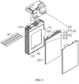
FIG. 5 is a breakdown structure diagram of the battery pack as shown inFIG. 4 . - The application will be further described in the following detailed description of the embodiments with reference to the above drawings.
- The technical solutions in the embodiments of the application will be clearly and completely described below in conjunction with the drawings in the embodiments of the application. Obviously, the described embodiments are only some, not all of the embodiments of the application.
- Unless otherwise defined, all technical and scientific terms used herein have the same meaning as those generally understood by those skilled in the art belonging to the technical field of the application. All terms used in the Description of the application only aim to describe the specific embodiments and are not intended to limit the application.
- Disclosed by some implementations of the application is a battery pack with a pressure relief structure, comprising: a housing, provided with an accommodating cavity; a cell assembly, accommodated in the accommodating cavity; a spacer, arranged between a first side of the cell assembly and the housing and provided with an air vent; a pressure relief part, arranged on the housing, wherein the pressure relief part is in contact with the spacer or an air channel is formed therebetween; and glue, filled in a gap between at least partial regions outside the first side of the cell assembly and the housing and used for fixing the cell assembly and the housing.
- The battery pack is provided with the spacer with the air vent, the spacer is arranged between the first side of the cell assembly and the housing, and the glue is filled in the gap between at least partial regions outside the first side of the cell assembly and the housing, so that no glue exists between the spacer and the cell assembly and a pressure relief channel for gas is formed. The housing is provided with the pressure relief part which is in contact with the spacer or has an air channel therewith, so that no glue exists between the spacer and the pressure relieve part and a pressure relief channel for gas is formed. Therefore, gas in the cell battery is discharged out of the cell assembly, and then discharged out of the battery pack through the pressure relief channel, the air vent and the pressure relief part.
- Some implementations of the application are elaborated in conjunction with the accompanying drawings. Without conflict, the following embodiments and features in these embodiments can be combined with each other.
- Referring to
FIG. 1 andFIG. 3 at the same time, disclosed by an embodiment of the application is abattery pack 100 with a pressure relief structure. Thebattery pack 100 comprises ahousing 10, acell assembly 20 and a spacer. In one embodiment, the spacer comprises aspacer 30 and aspacer 40. Thehousing 10 is provided with an accommodating cavity 101. Thecell assembly 20, thespacer 30 and thespacer 40 are respectively accommodated in the accommodating cavity 101 of thehousing 10. - Referring to
FIG. 4 andFIG. 5 , thecell assembly 20 comprises acell body 21 and atab 23. Thecell body 21 comprises atop seal 211 andside seals 213 located at both sides of thetop seal 211. Thetab 23 is arranged in thecell body 21 and extends out of thetop seal 211. Both ends of thetop seal 211 are connected to the twoside seals 213. The spacer is arranged between a first side of thecell assembly 20 and thehousing 10. The first side comprises one side of each of thetop seal 211 and theside seal 213 of thecell body 21, that is, thespacer 30 is located between thetop seal 211 of thecell assembly 20 and thehousing 10, and thespacer 40 is located between theside seal 213 of thecell assembly 20 and thehousing 10. Air vents (not shown) are formed in thespacer 30 and thespacer 40 respectively. -
Glue 200 is filled in the accommodating cavity 101. Theglue 200 is filled in a gap between at least partial regions outside the first side of thecell assembly 20 and thehousing 10. In one embodiment, theglue 200 is filled in the whole gaps among thecell assembly 20, thespacer 30 and thehousing 10, but is not filled between thespacer 30 and thetop seal 211 of thecell body 21 and between thespacer 40 and theside seal 213 of thecell body 21, but it is not limited thereto. For example, in other embodiments, theglue 200 may also be filled in the gaps among thecell assembly 20, thespacer 30 and thehousing 10, as long as theglue 200 can fix thecell assembly 20 and thehousing 10. When thebattery pack 100 is applied to a vibrating environment, the structural shock resistance and fixing strength of thebattery pack 100 are improved. In some embodiments, theglue 200 is also filled between the first side of the cell assembly and the housing. - Referring to 2, the
housing 10 is provided with a pressure relief part 11 and apressure relief part 13. The pressure relief part 11 is in contact with thespacer 30 or an air channel is formed therebetween to prevent theglue 200 from entering the space between the pressure relief part 11 and thespacer 30. Thespacer 30 is in contact with thetop seal 211 of thecell body 21 or an air channel is formed therebetween to prevent theglue 200 from entering the space between thespacer 30 and thetop seal 211. After the gas in thecell assembly 20 is discharged out of thecell body 21 from thetop seal 211, the gas may flow directly through the air vent of thespacer 30 to the space between the pressure relief part 11 and thespacer 30; the gas may also flow through the air vent of thespacer 30 to the space between the pressure relief part 11 and thespacer 30 after passing through the air channel between thespacer 30 and thetop seal 211. After passing through the air channel between the pressure relief part 11 and thespacer 30, the gas is discharged from the pressure relief part 11 to thehousing 10, or the gas is directly discharged from the pressure relief part 11 to thehousing 10. - The
pressure relief part 13 is in contact with thespacer 40 or an air channel is formed therebetween to prevent theglue 200 from entering the space between thepressure relief part 13 and thespacer 40. Thespacer 40 is in contact with theside seal 213 of thecell body 21 or an air channel is formed therebetween to prevent theglue 200 from entering the space between thespacer 40 and theside seal 213. After the gas in thecell assembly 20 is discharged out of thecell body 21 from thetop seal 211, the gas flows to the space between thespacer 40 and theside seal 213, and flows through the air vent of thespacer 40 to the space between thespacer 40 and thepressure relief part 13, and is finally discharged out of thehousing 10 from thepressure relief part 13. - The
spacer 30 and thespacer 40 are in air-permeable structures made of air-permeable materials. For example, the material of thespacer 30 and thespacer 40 is foam or sponge, or the like. - Referring to
FIG. 5 , thecell assembly 20 is provided with aweak region 201 that allows the gas to flow out of thecell assembly 20 when the weak region impacted by the gas in thecell assembly 20. At least part of thespacer 30 is attached to theweak region 201, or an air channel is provided between thespacer 30 and theweak region 201, so that when thehousing 10 is filled withglue 200, theweak region 201 is isolated from theglue 200 to ensure that theweak region 201 and thespacer 30 form a pressure relief channel for the gas to flow. The pressure relief part 11 is a vent structure arranged on thehousing 10. In one embodiment, at least a part, facing the pressure relief part 11, of thespacer 30 is attached to the inner wall of thehousing 10, so that thespacer 30 and the pressure relief part 11 are attached to each other. Furthermore, thespacer 30 and the pressure relief part 11 form a pressure relief channel for the gas to flow. It is understandable that, in other embodiments, thespacer 30 may also extend into the pressure relief part 11, so that thespacer 30 and the pressure relief part 11 extend, thereby preventing theglue 200 from entering the pressure relief part 11 and forming a pressure relief channel for the gas to flow between thespacer 30 and the pressure relief part 11. - The
top seal 211 is provided with one of theweak regions 201, and the length of theweak region 201 is the same as that of thetop seal 211, but is not limited thereto. For example, in other embodiments, theweak region 201 may also be shorter thantop seal 211. The number of theweak region 201 may also be two or other numbers, and these regions are arranged on thetop seal 211 at intervals. - The number of the
cell assembly 20 is six, but is not limited thereto. Every two of thecell assemblies 20 form a group and are attached to each other, and thetabs 23 of the twocell assemblies 20 extend towards each other and are stacked together. Anaccommodating groove 2111 is formed by thetabs 23 of the twocell assemblies 20 and thetop seal 211. The number of thespacers 30 is three. One of thespacers 30 is disposed in theaccommodating groove 2111 between two of thecell assemblies 20. Thespacer 30 is attached to theweak region 201 on thetop seal 211 of the twocell assemblies 20. It is understandable that, in other embodiments, the number of thecell assemblies 20 may also be one, two, or other numbers. - The
cell assembly 20 further comprises abracket 25. The side, away from thetop seal 211, of thetab 23, is disposed on thebracket 25, and thebracket 25 is used to support thetab 23. Thebracket 25 presses thespacer 30 on thetop seal 211. It is understandable that, in other embodiments, thespacer 30 may also be fixed to thecell assembly 20 by bonding, and the bonding position avoids theweak region 201 on thetop seal 211. - The number of the pressure relief parts 11 on the
housing 10 is six. Three of the pressure relief parts 11 are located on one side of thecell assembly 20, and the other three pressure relief parts 11 are located on the other side of thecell assembly 20. - Protruding
parts 31 are formed on both ends of thespacer 30. The protrudingpart 31 protrudes from both ends of thetop seal 211 and extends toward the pressure relief part 11, so that the protrudingpart 31 is attached to the pressure relief part 1. - It is understandable that, in other embodiments, the
spacer 30 may also be provided with a protrudingpart 31 at only one end. Accordingly, thehousing 10 is provided with the pressure relieve part 11 beside one side, corresponding to the protrudingpart 31, of thecell assembly 20, as long as the gas in thecell assembly 20 is discharged out of thebattery pack 100 after passing through the pressure relieve channel formed between theweak region 201 and thespacer 30 and passing through a pressure relief channel formed by the protrudingpart 31 and the pressure relief part 11. - The
side seal 213 of thecell assembly 20 is provided with at least oneweak region 203. Thespacer 40 is arranged inside thehousing 10 and is attached to theweak region 203 on theside seal 213, so that when thehousing 10 is filled withglue 200, theweak region 203 is isolated from theglue 200 to ensure that theweak region 203 and thespacer 40 form a pressure relief channel for gas to flow. Specifically, thespacer 40 is disposed on aside surface 215 of thecell assembly 20, and theside surface 215 is connected to thetop seal 211 and the two of the side seals 213, respectively. The side surfaces 215 of twoopposite cell assemblies 20 in two sets of thecell assemblies 20 are spaced apart to form agap 205, and thespacer 40 fills thegap 205, but it is not limited thereto. It is understandable that, in other embodiments, the side surfaces 215 of the twoopposite cell assemblies 20 in the two sets ofcell assemblies 20 may also be attached to each other. In other embodiments, thespacer 40 may be also in a structure similar to that of thespacer 30, specifically in a bar-shaped block structure, and thespacer 40 may also be bonded to theside seal 213 of thecell assembly 20. - An
avoidance hole 43 is formed in thespacer 40 to leave a space for thecell assembly 20 to deform. It is understandable that, in other embodiments, it is possible to omit theavoidance hole 43. - The
pressure relief part 13 is a through hole structure formed in thehousing 10. Thespacer 40 is provided with a protrudingpart 41 toward one side of thepressure relief part 13. The protrudingpart 41 protrudes from theside seal 213 and extends toward thepressure relief part 13 to be attached to the inner wall of thehousing 10, so that thespacer 40 is attached to thepressure relief part 13 and a pressure relief channel for gas to flow is thus formed between thespacer 40 and thepressure relief part 13. It is understandable that, in other embodiments, the protrudingpart 41 may also extend into thepressure relief part 13, so that thespacer 40 and thepressure relief part 13 are extended. - Referring to
Figs 1 and2 at the same time, thebattery pack 100 with a pressure relief structure further comprises anadhesive tape 50 and anadhesive tape 60. Theadhesive tape 50 and theadhesive tape 60 are respectively in a dust-proof and waterproof structure, so as to prevent dust, liquids or the like from entering the interior of thebattery pack 100. Theadhesive tape 50 and theadhesive tape 60 are respectively in a tape-like, sheet-like or film-like structure with a viscous substance on one side. Theadhesive tape 50 is bonded to the exterior of thehousing 10 and covers the pressure relief part 11. Theadhesive tape 60 is bonded to the exterior of thehousing 10 and covers thepressure relief part 13. The gas inside thecell assembly 20 impacts theadhesive tape 50 and theadhesive tape 60 by means of the pressure relief part 11 and thepressure relief part 13, so that theadhesive tape 50 and theadhesive tape 60 are completely or partially detached from thehousing 10. - In order to further make the
adhesive tape 50 and theadhesive tape 60 easily detach from thehousing 10, cutter lines (not shown) are formed in theadhesive tape 50 and theadhesive tape 60 respectively, so that theadhesive tape 50 and theadhesive tape 60 crack at the cutter lines when the tapes are impacted by the gas. It is understandable that, in other embodiments, it is possible to omit the cutter line. - The
housing 10 is also provided with a plurality ofgrooves 15 to accommodate theadhesive tape 50 and theadhesive tape 60. It is understandable that, in other embodiments, it is possible to omit thegroove 15. - It is understandable that the
housing 10 is not limited to using theadhesive tape 50 and theadhesive tape 60 to cover the pressure relief part 11 and the pressure relief part 14. For example, in another example, the pressure relief part may also be a weak structure (not shown) arranged on thehousing 10 and detached from the housing when being impacted by the gas in thecell assembly 20. The pressure relief part may be molded on thehousing 10, for example, the pressure relief part may be provided with a cutter line at a molded connection, so that the pressure relief part is easily broken at the cutter line when the pressure relief part is impacted by gas, then the pressure relief part is disconnected from thehousing 10, and the gas inside thecell assembly 20 is discharged from thebattery pack 100. In another embodiment, a structure such as a cutter line or a groove may also be directly formed in thehousing 10 to form a weak structure thinner than thehousing 10, so that the connection strength between the pressure relief part and thehousing 10 is weakened, and the pressure relief part is easy to crack when being impacted by gas, thus discharging gas from thebattery pack 100. - It is understandable that, in other embodiments, the
battery pack 100 may also comprise only thespacer 30 or only thespacer 40. Correspondingly, it is also possible to omit the pressure relief part 11 or thepressure relief part 13. The number of thespacers 30 and thespacers 40 is set according to the number of thecell assemblies 20 and the number of weak regions formed in thecell assemblies 20. - The
weak region 201 and theweak region 203 are respectively the weak regions formed at packaging interfaces of thecell assemblies 20 during packaging, but are not limited thereto. It is understandable that the weak region on thebattery pack 100 is not limited to being formed in thetop seal 211 and theside seal 213. The weak region may also be a weak structure that is designed on thecell body 21 and is easy to discharge the gas generated inside when the weak region is abnormal. Thespacer 30 or thespacer 40 may also be arranged between a second side of thecell assembly 20 and thehousing 10. The second side is a region other than regions at one side of each of thetop seal 211 and theside seal 213 of thecell assembly 20. The second side of thecell assembly 20 is provided with the weak structure, so that the gas is discharged from thecell assembly 20 through the weak structure, and flows to the pressure relief part 11 or the pressure relievepart 13 through thespacer 30 or thespacer 40 and is thus discharged from thehousing 10. For example, in other embodiments, the weak region may also be formed in theside surface 215 of thecell body 21, and thespacer 40 is attached to the weak region on theside surface 215 to isolate the weak region from theglue 200. The gas inside thecell assembly 20 is discharged from thebattery pack 100 through the weak region on theside surface 215, thespacer 40 and the pressure relief part 11 on thehousing 10. - The
battery pack 100 is provided with thespacer 20/40 with the air vent, thespacer 30/40 is arranged between the first side of thecell assembly 20 and thehousing 10, and theglue 200 is filled in the gap between at least partial regions outside the first side of thecell assembly 20 and thehousing 10, so that noglue 200 exists between thespacer 30/40 and thecell assembly 20 and a pressure relief channel for gas is formed. Thehousing 10 is provided with the pressure relief part 11/13 which is in contact with thespacer 30/40 or has an air channel therewith, so that noglue 200 exists between thespacer 30/40 and the pressure relieve part 11/13 and a pressure relief channel for gas is formed. Therefore, gas in thecell battery 20 is discharged out of thecell assembly 20, and then discharged out of thebattery pack 100 through the pressure relief channel, the air vent and the pressure relief part 11/13. - The above embodiments are merely used to illustrate, instead of limiting, the technical solution of the application. Although the application is elaborated with reference to the preferred embodiments, those of ordinary skill in the art should understood to amend or equivalently replace the technical solution of the application without departure from the spirit and essential characteristics thereof.
| |
100 |
| |
10 |
| Accommodating cavity | 101 |
| |
11, 13 |
| |
15 |
| |
20 |
| |
201, 203 |
| |
205 |
| |
21 |
| |
211 |
| Accommodating |
2111 |
| |
213 |
| |
215 |
| |
23 |
| |
25 |
| |
30, 40 |
| Protruding |
31,41 |
| |
43 |
| |
50, 60 |
| |
200 |
Claims (13)
- A battery pack with a pressure relief structure, comprising:a housing, provided with an accommodating cavity; anda cell assembly, accommodated in the accommodating cavity, wherein the battery pack further comprises:a spacer, arranged between a first side of the cell assembly and the housing and provided with an air vent;a pressure relief part, arranged on the housing, wherein the pressure relief part is in contact with the spacer or an air channel is formed therebetween; andglue, filled in a gap between at least partial regions outside the first side of the cell assembly and the housing and used for fixing the cell assembly and the housing.
- The battery pack according to claim 1, wherein the cell assembly comprises a cell body and a tab;the cell body is provided with a top seal at the first side;the tab is arranged in the cell body and extends out of one side of the top seal;the top seal is provided with at least one weak region enabling gas in the cell body to flow out of the cell body when the weak region is impacted by the gas; andthe spacer is arranged between the top seal and the housing and separates the glue from the weak region.
- The battery pack according to claim 2, wherein the spacer is attached to the weak region on the top seal, or an air channel is formed between the spacer and the weak region, the spacer is provided with a protruding part, and the protruding part protrudes from the top seal and extends to the pressure relief part.
- The battery pack according to claim 3, wherein the cell assembly further comprises a bracket supporting the tab, and the bracket presses the spacer on the top seal.
- The battery pack according to claim 1, wherein the cell assembly comprises a cell body and a tab;the tab is arranged in the cell body and extends out of the cell body; andat least one side seal is arranged at the first side of the cell body, and the side seal is located at one side of the tab; andthe side seal is provided with at least one weak region enabling gas in the cell body to flow out of the cell body when the weak region is impacted by the gas; andthe spacer is arranged between the side seal and the housing and separates the glue from the weak region.
- The battery pack according to claim 5, wherein the spacer is attached to the weak region on the top seal, or an air channel is formed between the spacer and the weak region, the spacer is provided with a protruding part, and the protruding part protrudes from the top seal and extends to the pressure relief part.
- The battery pack according to claim 5, wherein multiple cell assemblies are provided, the spacer fills the gap between two of the cell assemblies, and the spacer is provided with an avoidance hole to leave a space for the cell assemblies to deform.
- The battery pack according to claim 1, wherein the pressure relief part is an air vent structure arranged on the housing, and the spacer at least partially extends into the pressure relief part or is attached thereto.
- The battery pack according to claim 8, wherein the battery pack further comprises an adhesive tape, and the adhesive tape is bonded to the exterior of the housing and covers the pressure relief part.
- The battery pack according to claim 9, wherein the adhesive tape is in a dustproof and waterproof structure.
- The battery pack according to claim 9, wherein a cutter line is formed in the adhesive tape.
- The battery pack according to claim 1, wherein the pressure relief part is a weak structure arranged on the housing and detached from the housing when being impacted by gas in the cell assembly.
- The battery pack according to claim 1, wherein the glue is also filled between a first side of the cell assembly and the housing.
Applications Claiming Priority (1)
| Application Number | Priority Date | Filing Date | Title |
|---|---|---|---|
| PCT/CN2020/096850 WO2021253334A1 (en) | 2020-06-18 | 2020-06-18 | Battery pack having pressure relief structure |
Publications (3)
| Publication Number | Publication Date |
|---|---|
| EP3958382A1 true EP3958382A1 (en) | 2022-02-23 |
| EP3958382A4 EP3958382A4 (en) | 2022-04-27 |
| EP3958382B1 EP3958382B1 (en) | 2026-03-04 |
Family
ID=78237887
Family Applications (1)
| Application Number | Title | Priority Date | Filing Date |
|---|---|---|---|
| EP20866929.1A Active EP3958382B1 (en) | 2020-06-18 | 2020-06-18 | Battery pack having pressure relief structure |
Country Status (4)
| Country | Link |
|---|---|
| US (1) | US20210399380A1 (en) |
| EP (1) | EP3958382B1 (en) |
| CN (1) | CN113597708B (en) |
| WO (1) | WO2021253334A1 (en) |
Families Citing this family (2)
| Publication number | Priority date | Publication date | Assignee | Title |
|---|---|---|---|---|
| CN116914342A (en) * | 2022-08-19 | 2023-10-20 | 孚能科技(赣州)股份有限公司 | Directional pressure release clamp plate, radiating component, battery stack module and battery package |
| CN120613537A (en) * | 2024-03-06 | 2025-09-09 | 宁德时代新能源科技股份有限公司 | Battery pack, battery module, battery unit and power-consuming device |
Family Cites Families (22)
| Publication number | Priority date | Publication date | Assignee | Title |
|---|---|---|---|---|
| US20030232236A1 (en) * | 2002-06-14 | 2003-12-18 | Mitchell Porter H. | Battery package vent |
| EP1780865B1 (en) * | 2005-10-31 | 2017-02-22 | Black & Decker, Inc. | Thermal management system for a battery pack |
| KR101009567B1 (en) * | 2008-12-05 | 2011-01-18 | 삼성에스디아이 주식회사 | Battery pack |
| EP2412043A2 (en) * | 2009-03-27 | 2012-02-01 | Johnson Controls Saft Advanced Power Solutions LLC | A battery module having a sealed vent chamber |
| CN102130313A (en) * | 2010-01-12 | 2011-07-20 | 比克国际(天津)有限公司 | Soft packaging battery and battery pack |
| KR20120095158A (en) * | 2011-02-18 | 2012-08-28 | 삼성에스디아이 주식회사 | Rechargeable battery |
| KR101866355B1 (en) * | 2011-03-25 | 2018-06-12 | 에스케이이노베이션 주식회사 | Gas exhaust device of pouch type secondary battery |
| US20130330579A1 (en) * | 2011-03-25 | 2013-12-12 | Hitachi Vehicle Energy, Ltd. | Battery block and power supply device |
| JP2012248299A (en) * | 2011-05-25 | 2012-12-13 | Sanyo Electric Co Ltd | Battery module, battery system, electric vehicle, mobile object, power storage device and power supply device |
| KR101392799B1 (en) * | 2012-06-07 | 2014-05-14 | 주식회사 엘지화학 | Battery Module Having Structure of Improved Stability and High Cooling Efficiency |
| CN106469791A (en) * | 2015-08-18 | 2017-03-01 | 有量科技股份有限公司 | Lithium battery module |
| CN204966569U (en) * | 2015-09-01 | 2016-01-13 | 湖南文理学院 | Lithium ion power batteries with pressure release and explosion -proof function |
| KR102125238B1 (en) * | 2016-01-06 | 2020-06-22 | 주식회사 엘지화학 | Device for Estimating Degree of Thickness Expansion of Battery Cell and Method for Estimation Using the Same |
| JP6577375B2 (en) * | 2016-01-19 | 2019-09-18 | カルソニックカンセイ株式会社 | Assembled battery and method of manufacturing the assembled battery |
| CN206490119U (en) * | 2017-02-28 | 2017-09-12 | 宁德时代新能源科技股份有限公司 | Battery modules |
| US20180261813A1 (en) * | 2017-03-10 | 2018-09-13 | NextEv USA, Inc. | Thermally conductive potting for module retainer and thermal link |
| US10601090B2 (en) * | 2017-04-28 | 2020-03-24 | Nio Usa, Inc. | Using a spacer to block path of thermally conductive structural adhesive in lithium ion cells |
| KR102432481B1 (en) * | 2018-01-19 | 2022-08-16 | 삼성전자 주식회사 | electronic device and method for sensing condition of battery |
| CN207818695U (en) * | 2018-01-25 | 2018-09-04 | 宁德时代新能源科技股份有限公司 | Battery Unit and Battery Module |
| CN209029420U (en) * | 2018-08-21 | 2019-06-25 | 东莞塔菲尔新能源科技有限公司 | The assembling structure of power battery top cover and battery core |
| CN209947879U (en) * | 2019-04-11 | 2020-01-14 | 上海捷新动力电池系统有限公司 | Soft package battery packaging structure |
| CN212517400U (en) * | 2020-06-18 | 2021-02-09 | 东莞新能安科技有限公司 | Battery pack with pressure relief structure |
-
2020
- 2020-06-18 CN CN202080021568.5A patent/CN113597708B/en active Active
- 2020-06-18 WO PCT/CN2020/096850 patent/WO2021253334A1/en not_active Ceased
- 2020-06-18 EP EP20866929.1A patent/EP3958382B1/en active Active
-
2021
- 2021-03-31 US US17/219,739 patent/US20210399380A1/en not_active Abandoned
Also Published As
| Publication number | Publication date |
|---|---|
| US20210399380A1 (en) | 2021-12-23 |
| EP3958382B1 (en) | 2026-03-04 |
| CN113597708B (en) | 2022-12-20 |
| WO2021253334A1 (en) | 2021-12-23 |
| CN113597708A (en) | 2021-11-02 |
| EP3958382A4 (en) | 2022-04-27 |
Similar Documents
| Publication | Publication Date | Title |
|---|---|---|
| US8777009B2 (en) | Packing structure for a thin display device | |
| EP3958382B1 (en) | Battery pack having pressure relief structure | |
| US10061412B2 (en) | Mobile information display terminal | |
| CN212517400U (en) | Battery pack with pressure relief structure | |
| WO2015060528A1 (en) | Battery module having improved vibration characteristic and frame cartridge assembly applied thereto | |
| KR20190087746A (en) | Battery module housing having a reusable, recyclable or reworkable adhesive structure and Battery module the same | |
| KR20170068261A (en) | Secondary battery module improved in end plate structure and end plate member for the same | |
| JP2012097896A (en) | Seal structure using gasket | |
| KR102131613B1 (en) | battery case and manufacturing methods therof | |
| EP4040580A1 (en) | Battery cell holder group and energy storage device package comprising same | |
| US10340482B2 (en) | Energy storage apparatus | |
| CN113728500B (en) | Battery pack | |
| CN109256415A (en) | display module and display device | |
| EP4243172A1 (en) | Battery cell module and battery system | |
| US9501095B2 (en) | Display device | |
| JP2024505848A (en) | Battery pack, method for manufacturing battery pack, and electricity usage equipment | |
| EP4152498A1 (en) | Battery housing and battery pack having same | |
| US20220115729A1 (en) | Battery and electric apparatus | |
| CN110703507B (en) | Display assembly | |
| US12224448B2 (en) | Cell frame set and energy storage device package including cell frame set | |
| US20210333916A1 (en) | Touch display device | |
| EP4276992B1 (en) | Battery module | |
| KR20220153818A (en) | Structure Of Insulation For Passive Typed Container For Constant Temperature | |
| CN223427632U (en) | Battery box and battery pack | |
| CN212936097U (en) | Loudspeaker |
Legal Events
| Date | Code | Title | Description |
|---|---|---|---|
| STAA | Information on the status of an ep patent application or granted ep patent |
Free format text: STATUS: UNKNOWN |
|
| STAA | Information on the status of an ep patent application or granted ep patent |
Free format text: STATUS: THE INTERNATIONAL PUBLICATION HAS BEEN MADE |
|
| PUAI | Public reference made under article 153(3) epc to a published international application that has entered the european phase |
Free format text: ORIGINAL CODE: 0009012 |
|
| STAA | Information on the status of an ep patent application or granted ep patent |
Free format text: STATUS: REQUEST FOR EXAMINATION WAS MADE |
|
| 17P | Request for examination filed |
Effective date: 20210330 |
|
| AK | Designated contracting states |
Kind code of ref document: A1 Designated state(s): AL AT BE BG CH CY CZ DE DK EE ES FI FR GB GR HR HU IE IS IT LI LT LU LV MC MK MT NL NO PL PT RO RS SE SI SK SM TR |
|
| A4 | Supplementary search report drawn up and despatched |
Effective date: 20220324 |
|
| RIC1 | Information provided on ipc code assigned before grant |
Ipc: H01M 50/35 20210101ALI20220319BHEP Ipc: H01M 50/289 20210101ALI20220319BHEP Ipc: H01M 50/204 20210101ALI20220319BHEP Ipc: H01M 50/291 20210101ALI20220319BHEP Ipc: H01M 50/244 20210101AFI20220319BHEP |
|
| DAV | Request for validation of the european patent (deleted) | ||
| DAX | Request for extension of the european patent (deleted) | ||
| RIC1 | Information provided on ipc code assigned before grant |
Ipc: H01M 50/244 20210101AFI20250814BHEP Ipc: H01M 50/291 20210101ALI20250814BHEP Ipc: H01M 50/204 20210101ALI20250814BHEP Ipc: H01M 50/289 20210101ALI20250814BHEP Ipc: H01M 50/35 20210101ALI20250814BHEP Ipc: H01M 50/209 20210101ALI20250814BHEP Ipc: H01M 50/342 20210101ALI20250814BHEP Ipc: H01M 50/30 20210101ALI20250814BHEP |
|
| GRAP | Despatch of communication of intention to grant a patent |
Free format text: ORIGINAL CODE: EPIDOSNIGR1 |
|
| STAA | Information on the status of an ep patent application or granted ep patent |
Free format text: STATUS: GRANT OF PATENT IS INTENDED |
|
| INTG | Intention to grant announced |
Effective date: 20250924 |
|
| RAP1 | Party data changed (applicant data changed or rights of an application transferred) |
Owner name: NINGDE AMPEREX TECHNOLOGY LTD. |
|
| GRAS | Grant fee paid |
Free format text: ORIGINAL CODE: EPIDOSNIGR3 |
|
| GRAA | (expected) grant |
Free format text: ORIGINAL CODE: 0009210 |
|
| STAA | Information on the status of an ep patent application or granted ep patent |
Free format text: STATUS: THE PATENT HAS BEEN GRANTED |
|
| AK | Designated contracting states |
Kind code of ref document: B1 Designated state(s): AL AT BE BG CH CY CZ DE DK EE ES FI FR GB GR HR HU IE IS IT LI LT LU LV MC MK MT NL NO PL PT RO RS SE SI SK SM TR |
|
| REG | Reference to a national code |
Ref country code: CH Ref legal event code: F10 Free format text: ST27 STATUS EVENT CODE: U-0-0-F10-F00 (AS PROVIDED BY THE NATIONAL OFFICE) Effective date: 20260304 Ref country code: GB Ref legal event code: FG4D |
|
| REG | Reference to a national code |
Ref country code: DE Ref legal event code: R096 Ref document number: 602020068150 Country of ref document: DE |
|
| REG | Reference to a national code |
Ref country code: IE Ref legal event code: FG4D |
|
| REG | Reference to a national code |
Ref country code: NL Ref legal event code: FP |