EP3958352A1 - Secondary battery, production method therefor, and device comprising same - Google Patents
Secondary battery, production method therefor, and device comprising same Download PDFInfo
- Publication number
- EP3958352A1 EP3958352A1 EP20932863.2A EP20932863A EP3958352A1 EP 3958352 A1 EP3958352 A1 EP 3958352A1 EP 20932863 A EP20932863 A EP 20932863A EP 3958352 A1 EP3958352 A1 EP 3958352A1
- Authority
- EP
- European Patent Office
- Prior art keywords
- negative electrode
- active material
- electrode active
- secondary battery
- electrode film
- Prior art date
- Legal status (The legal status is an assumption and is not a legal conclusion. Google has not performed a legal analysis and makes no representation as to the accuracy of the status listed.)
- Granted
Links
Images

Classifications
-
- H—ELECTRICITY
- H01—ELECTRIC ELEMENTS
- H01M—PROCESSES OR MEANS, e.g. BATTERIES, FOR THE DIRECT CONVERSION OF CHEMICAL ENERGY INTO ELECTRICAL ENERGY
- H01M4/00—Electrodes
- H01M4/02—Electrodes composed of, or comprising, active material
- H01M4/36—Selection of substances as active materials, active masses, active liquids
- H01M4/362—Composites
- H01M4/366—Composites as layered products
-
- H—ELECTRICITY
- H01—ELECTRIC ELEMENTS
- H01M—PROCESSES OR MEANS, e.g. BATTERIES, FOR THE DIRECT CONVERSION OF CHEMICAL ENERGY INTO ELECTRICAL ENERGY
- H01M4/00—Electrodes
- H01M4/02—Electrodes composed of, or comprising, active material
- H01M4/13—Electrodes for accumulators with non-aqueous electrolyte, e.g. for lithium-accumulators; Processes of manufacture thereof
- H01M4/133—Electrodes based on carbonaceous material, e.g. graphite-intercalation compounds or CFx
-
- C—CHEMISTRY; METALLURGY
- C01—INORGANIC CHEMISTRY
- C01B—NON-METALLIC ELEMENTS; COMPOUNDS THEREOF; METALLOIDS OR COMPOUNDS THEREOF NOT COVERED BY SUBCLASS C01C
- C01B32/00—Carbon; Compounds thereof
- C01B32/20—Graphite
-
- H—ELECTRICITY
- H01—ELECTRIC ELEMENTS
- H01M—PROCESSES OR MEANS, e.g. BATTERIES, FOR THE DIRECT CONVERSION OF CHEMICAL ENERGY INTO ELECTRICAL ENERGY
- H01M4/00—Electrodes
- H01M4/02—Electrodes composed of, or comprising, active material
- H01M4/04—Processes of manufacture in general
- H01M4/0402—Methods of deposition of the material
- H01M4/0404—Methods of deposition of the material by coating on electrode collectors
-
- H—ELECTRICITY
- H01—ELECTRIC ELEMENTS
- H01M—PROCESSES OR MEANS, e.g. BATTERIES, FOR THE DIRECT CONVERSION OF CHEMICAL ENERGY INTO ELECTRICAL ENERGY
- H01M4/00—Electrodes
- H01M4/02—Electrodes composed of, or comprising, active material
- H01M4/13—Electrodes for accumulators with non-aqueous electrolyte, e.g. for lithium-accumulators; Processes of manufacture thereof
- H01M4/139—Processes of manufacture
- H01M4/1391—Processes of manufacture of electrodes based on mixed oxides or hydroxides, or on mixtures of oxides or hydroxides, e.g. LiCoOx
-
- H—ELECTRICITY
- H01—ELECTRIC ELEMENTS
- H01M—PROCESSES OR MEANS, e.g. BATTERIES, FOR THE DIRECT CONVERSION OF CHEMICAL ENERGY INTO ELECTRICAL ENERGY
- H01M4/00—Electrodes
- H01M4/02—Electrodes composed of, or comprising, active material
- H01M4/13—Electrodes for accumulators with non-aqueous electrolyte, e.g. for lithium-accumulators; Processes of manufacture thereof
- H01M4/139—Processes of manufacture
- H01M4/1393—Processes of manufacture of electrodes based on carbonaceous material, e.g. graphite-intercalation compounds or CFx
-
- H—ELECTRICITY
- H01—ELECTRIC ELEMENTS
- H01M—PROCESSES OR MEANS, e.g. BATTERIES, FOR THE DIRECT CONVERSION OF CHEMICAL ENERGY INTO ELECTRICAL ENERGY
- H01M4/00—Electrodes
- H01M4/02—Electrodes composed of, or comprising, active material
- H01M4/36—Selection of substances as active materials, active masses, active liquids
- H01M4/48—Selection of substances as active materials, active masses, active liquids of inorganic oxides or hydroxides
- H01M4/50—Selection of substances as active materials, active masses, active liquids of inorganic oxides or hydroxides of manganese
- H01M4/505—Selection of substances as active materials, active masses, active liquids of inorganic oxides or hydroxides of manganese of mixed oxides or hydroxides containing manganese for inserting or intercalating light metals, e.g. LiMn2O4 or LiMn2OxFy
-
- H—ELECTRICITY
- H01—ELECTRIC ELEMENTS
- H01M—PROCESSES OR MEANS, e.g. BATTERIES, FOR THE DIRECT CONVERSION OF CHEMICAL ENERGY INTO ELECTRICAL ENERGY
- H01M4/00—Electrodes
- H01M4/02—Electrodes composed of, or comprising, active material
- H01M4/36—Selection of substances as active materials, active masses, active liquids
- H01M4/48—Selection of substances as active materials, active masses, active liquids of inorganic oxides or hydroxides
- H01M4/52—Selection of substances as active materials, active masses, active liquids of inorganic oxides or hydroxides of nickel, cobalt or iron
- H01M4/525—Selection of substances as active materials, active masses, active liquids of inorganic oxides or hydroxides of nickel, cobalt or iron of mixed oxides or hydroxides containing iron, cobalt or nickel for inserting or intercalating light metals, e.g. LiNiO2, LiCoO2 or LiCoOxFy
-
- H—ELECTRICITY
- H01—ELECTRIC ELEMENTS
- H01M—PROCESSES OR MEANS, e.g. BATTERIES, FOR THE DIRECT CONVERSION OF CHEMICAL ENERGY INTO ELECTRICAL ENERGY
- H01M4/00—Electrodes
- H01M4/02—Electrodes composed of, or comprising, active material
- H01M4/36—Selection of substances as active materials, active masses, active liquids
- H01M4/58—Selection of substances as active materials, active masses, active liquids of inorganic compounds other than oxides or hydroxides, e.g. sulfides, selenides, tellurides, halogenides or LiCoFy; of polyanionic structures, e.g. phosphates, silicates or borates
- H01M4/583—Carbonaceous material, e.g. graphite-intercalation compounds or CFx
- H01M4/587—Carbonaceous material, e.g. graphite-intercalation compounds or CFx for inserting or intercalating light metals
-
- C—CHEMISTRY; METALLURGY
- C01—INORGANIC CHEMISTRY
- C01P—INDEXING SCHEME RELATING TO STRUCTURAL AND PHYSICAL ASPECTS OF SOLID INORGANIC COMPOUNDS
- C01P2002/00—Crystal-structural characteristics
- C01P2002/70—Crystal-structural characteristics defined by measured X-ray, neutron or electron diffraction data
-
- C—CHEMISTRY; METALLURGY
- C01—INORGANIC CHEMISTRY
- C01P—INDEXING SCHEME RELATING TO STRUCTURAL AND PHYSICAL ASPECTS OF SOLID INORGANIC COMPOUNDS
- C01P2004/00—Particle morphology
- C01P2004/20—Particle morphology extending in two dimensions, e.g. plate-like
-
- C—CHEMISTRY; METALLURGY
- C01—INORGANIC CHEMISTRY
- C01P—INDEXING SCHEME RELATING TO STRUCTURAL AND PHYSICAL ASPECTS OF SOLID INORGANIC COMPOUNDS
- C01P2004/00—Particle morphology
- C01P2004/30—Particle morphology extending in three dimensions
- C01P2004/32—Spheres
-
- C—CHEMISTRY; METALLURGY
- C01—INORGANIC CHEMISTRY
- C01P—INDEXING SCHEME RELATING TO STRUCTURAL AND PHYSICAL ASPECTS OF SOLID INORGANIC COMPOUNDS
- C01P2004/00—Particle morphology
- C01P2004/60—Particles characterised by their size
- C01P2004/61—Micrometer sized, i.e. from 1-100 micrometer
-
- C—CHEMISTRY; METALLURGY
- C01—INORGANIC CHEMISTRY
- C01P—INDEXING SCHEME RELATING TO STRUCTURAL AND PHYSICAL ASPECTS OF SOLID INORGANIC COMPOUNDS
- C01P2006/00—Physical properties of inorganic compounds
- C01P2006/11—Powder tap density
-
- C—CHEMISTRY; METALLURGY
- C01—INORGANIC CHEMISTRY
- C01P—INDEXING SCHEME RELATING TO STRUCTURAL AND PHYSICAL ASPECTS OF SOLID INORGANIC COMPOUNDS
- C01P2006/00—Physical properties of inorganic compounds
- C01P2006/12—Surface area
-
- H—ELECTRICITY
- H01—ELECTRIC ELEMENTS
- H01M—PROCESSES OR MEANS, e.g. BATTERIES, FOR THE DIRECT CONVERSION OF CHEMICAL ENERGY INTO ELECTRICAL ENERGY
- H01M10/00—Secondary cells; Manufacture thereof
- H01M10/05—Accumulators with non-aqueous electrolyte
- H01M10/052—Li-accumulators
- H01M10/0525—Rocking-chair batteries, i.e. batteries with lithium insertion or intercalation in both electrodes; Lithium-ion batteries
-
- H—ELECTRICITY
- H01—ELECTRIC ELEMENTS
- H01M—PROCESSES OR MEANS, e.g. BATTERIES, FOR THE DIRECT CONVERSION OF CHEMICAL ENERGY INTO ELECTRICAL ENERGY
- H01M4/00—Electrodes
- H01M4/02—Electrodes composed of, or comprising, active material
- H01M2004/021—Physical characteristics, e.g. porosity, surface area
-
- H—ELECTRICITY
- H01—ELECTRIC ELEMENTS
- H01M—PROCESSES OR MEANS, e.g. BATTERIES, FOR THE DIRECT CONVERSION OF CHEMICAL ENERGY INTO ELECTRICAL ENERGY
- H01M4/00—Electrodes
- H01M4/02—Electrodes composed of, or comprising, active material
- H01M2004/026—Electrodes composed of, or comprising, active material characterised by the polarity
- H01M2004/027—Negative electrodes
-
- H—ELECTRICITY
- H01—ELECTRIC ELEMENTS
- H01M—PROCESSES OR MEANS, e.g. BATTERIES, FOR THE DIRECT CONVERSION OF CHEMICAL ENERGY INTO ELECTRICAL ENERGY
- H01M4/00—Electrodes
- H01M4/02—Electrodes composed of, or comprising, active material
- H01M2004/026—Electrodes composed of, or comprising, active material characterised by the polarity
- H01M2004/028—Positive electrodes
-
- H—ELECTRICITY
- H01—ELECTRIC ELEMENTS
- H01M—PROCESSES OR MEANS, e.g. BATTERIES, FOR THE DIRECT CONVERSION OF CHEMICAL ENERGY INTO ELECTRICAL ENERGY
- H01M2220/00—Batteries for particular applications
- H01M2220/20—Batteries in motive systems, e.g. vehicle, ship, plane
-
- Y—GENERAL TAGGING OF NEW TECHNOLOGICAL DEVELOPMENTS; GENERAL TAGGING OF CROSS-SECTIONAL TECHNOLOGIES SPANNING OVER SEVERAL SECTIONS OF THE IPC; TECHNICAL SUBJECTS COVERED BY FORMER USPC CROSS-REFERENCE ART COLLECTIONS [XRACs] AND DIGESTS
- Y02—TECHNOLOGIES OR APPLICATIONS FOR MITIGATION OR ADAPTATION AGAINST CLIMATE CHANGE
- Y02E—REDUCTION OF GREENHOUSE GAS [GHG] EMISSIONS, RELATED TO ENERGY GENERATION, TRANSMISSION OR DISTRIBUTION
- Y02E60/00—Enabling technologies; Technologies with a potential or indirect contribution to GHG emissions mitigation
- Y02E60/10—Energy storage using batteries
-
- Y—GENERAL TAGGING OF NEW TECHNOLOGICAL DEVELOPMENTS; GENERAL TAGGING OF CROSS-SECTIONAL TECHNOLOGIES SPANNING OVER SEVERAL SECTIONS OF THE IPC; TECHNICAL SUBJECTS COVERED BY FORMER USPC CROSS-REFERENCE ART COLLECTIONS [XRACs] AND DIGESTS
- Y02—TECHNOLOGIES OR APPLICATIONS FOR MITIGATION OR ADAPTATION AGAINST CLIMATE CHANGE
- Y02P—CLIMATE CHANGE MITIGATION TECHNOLOGIES IN THE PRODUCTION OR PROCESSING OF GOODS
- Y02P70/00—Climate change mitigation technologies in the production process for final industrial or consumer products
- Y02P70/50—Manufacturing or production processes characterised by the final manufactured product
Definitions
- the present application belongs to the field of electrochemical technology and, more specifically, relates to a secondary battery, a process for preparing the same and an apparatuses containing the secondary battery.
- Secondary battery is widely used in various consumer electronic products and electric vehicles due to its outstanding characteristics of light weight, no pollution, and no memory effect.
- the present application provides a secondary battery, a process for preparing the same and an apparatus including the secondary battery, which aims at achieving both better low temperature rate performance and longer high temperature cycle life while the secondary battery has a high energy density.
- a second aspect of the present application provides a process for preparing a secondary battery, comprising preparing a negative electrode plate of the secondary battery by the following steps:
- a third aspect of the present application provides an apparatus comprising a secondary battery according to the first aspect of the present application or a secondary battery prepared according to the process of the second aspect of the present application.
- the negative electrode plate comprises a first negative electrode film and a second negative electrode film and in the first negative electrode film, a first negative electrode active material with a particular composition is set, so that the secondary battery can have better low temperature rate performance and longer high temperature cycle life on the premise of higher energy density.
- any lower limit can be combined with any upper limit as an unspecified range; any lower limit can be combined with any other lower limit as an unspecified range, and any upper limit can be combined with any other upper limit as an unspecified range.
- each point or single value between endpoints of a range is included in the range.
- each point or single value, as a lower limit or an upper limit can be combined with any other point or single value or combined with any other lower or upper limit to form an unspecified range.
- the first aspect of the application provides a secondary battery.
- the secondary battery comprises a positive electrode plate, a negative electrode plate and an electrolyte.
- active ions are intercalated and de-intercalated between positive and negative electrode plates.
- Electrolytes act as conducting ions between positive and negative electrode plates.
- the battery can have better low-temperature rate performance under the premise of higher energy density.
- the first negative electrode active material of the present application comprises natural graphite
- the second negative electrode active material comprises artificial graphite
- S1 of the first negative electrode active material is controlled within the given range
- active sites of upper and lower layers in the negative electrode plate are reasonably matched, which is conducive to improving rate performance of the battery.
- porosities of the upper and lower layers are also reasonably optimized, which is conducive to electrolyte infiltration and improving cycle life of the battery.
- the first negative electrode active material satisfies 0.70 ⁇ S1 ⁇ 0.80.
- the inventors have conducted intensive studies to find that, on the basis that the negative electrode plate according to the present application satisfies the foregoing requirements, the performance of the battery can be further improved in the event that it optionally satisfies one or more of the following requirements.
- the first negative electrode active material has a graphitization degree of from 95% to 98%, preferably from 96% to 97%.
- the second negative electrode active material has a graphitization degree of from 90% to 95%, preferably from 91% to 93%.
- the first negative electrode active material has a powder compaction density of from 1.85 g/cm 3 to 2.1 g/cm 3 , preferably from 1.9 g/cm 3 to 2.0 g/cm 3 under a pressure of 50,000 N.
- the second negative electrode active material has a powder compaction density of from 1.7 g/cm 3 to 1.9 g/cm 3 , preferably from 1.8 g/cm 3 to 1.9 g/cm 3 under a pressure of 50,000 N.
- the first negative electrode active material has a specific surface area (SSA) of from 1.6 m 2 /g to 2.4 m 2 /g, preferably from 1.8 m 2 /g to 2.2 m 2 /g.
- SSA specific surface area
- the second negative electrode active material has a specific surface area (SSA) of from 0.7 m 2 /g to 1.5 m 2 /g, preferably from 0.9 m 2 /g to 1.3 m 2 /g.
- SSA specific surface area
- the volume average particle size DV50 of the first negative electrode active material is greater than the volume average particle size DV50 of the second negative electrode active material.
- the volume average particle size DV50 of the first negative electrode active material is from 15 ⁇ m to 19 ⁇ m, preferably from 16 ⁇ m to 18 ⁇ m.
- the volume average particle size DV50 of the second negative electrode active material is from 14 ⁇ m to 18 ⁇ m, preferably from 15 ⁇ m to 17 ⁇ m.
- the natural graphite has a morphology that is one or more of spherical and quasi-spherical.
- the artificial graphite has a morphology that is one or more of a block shape and a sheet shape.
- the natural graphite is present in the first negative electrode active material in a mass percentage of ⁇ 50%, more preferably from 80% to 100%.
- the artificial graphite is present in the second negative electrode active material in a mass ratio of is ⁇ 80%, more preferably 90%-100%.
- W2H and W3R are well known in the art and can be tested by methods known in the art. For example, it can be tested with an X-ray diffractometer (such as Bruker D8 Discover). Then, the value of S1 can be obtained by calculation with the formula of the present application.
- the graphitization degree of material has a common meaning in this field and can be tested using methods already known in this field.
- the test could be performed using an X-ray diffractometer (e.g. Bruker D8 Discover).
- D V 50 of the material has a meaning known in the art and can be tested using methods known in the art. It can be measured, for example, by a laser diffraction particle size distribution tester (e.g., a Malvern Mastersizer 3000) with reference to particle size laser diffraction e.g. the standard GB/T19077-2016. D v 50 refers to the corresponding particle size when the cumulative volume percentage of the material reaches 50%.
- a laser diffraction particle size distribution tester e.g., a Malvern Mastersizer 3000
- D v 50 refers to the corresponding particle size when the cumulative volume percentage of the material reaches 50%.
- the power compacted density of a material has a common meaning in the art and can be tested by the method known in this field.
- the test could be implemented with reference to GB/T 24533-2009 using an electronic pressure testing machine (such as UTM7305) as follows: putting a certain amount of powder on a special mold for compaction, setting different pressure, reading the thickness of the powder on the apparatus under different pressure, and calculating the compacted density under different pressure.
- the pressure is set to be 50,000N.
- the specific surface area (SSA) of a material has a common meaning in the art and can be tested by the method known in this field.
- it may be tested with a nitrogen adsorption specific surface area analysis test method and calculated by a BET (Brunauer Emmett Teller) method, wherein the nitrogen adsorption specific surface area analysis test can be implemented using NOVA 2000e specific surface area and pore size analyzer of Conta Company, USA.
- BET Brunauer Emmett Teller
- the morphology of a negative electrode active material has a well-known meaning in the art, and can be tested by methods known in the art.
- the electrode active material is stuck on a conductive adhesive, and tested with a scanning electron microscope (such as sigma300) for morphology of particles. The test can be carried out with reference to JY/T010-1996.
- test samples are taken from the negative electrode film after cold pressing, as an example, they can be sampled as follows:
- the boundary between the first negative electrode film and the second negative electrode film can be determined with the aid of an optical microscope or a scanning electron microscope.
- the negative electrode film has a thickness of preferably ⁇ 60 ⁇ m, more preferably from 65 ⁇ m to 80 ⁇ m. It should be noted that the thickness of the negative electrode film refers to the total thickness of the negative electrode film (that is, the sum of the thicknesses of the first negative electrode film and the second negative electrode film).
- the negative electrode film has an areal density of 10 mg/cm 2 ⁇ CW ⁇ 13 mg/cm 2 , preferably, 10.5 mg/cm 2 ⁇ CW ⁇ 11.5 mg/cm 2 . It should be noted that the areal density of the negative electrode film refers to the areal density of the whole negative electrode film (that is, the sum of the areal density of the first negative electrode film and the second negative electrode film).
- the thickness ratio of the first negative electrode film to the second negative electrode film is from 1:1.01 to 1:1.1, preferably from 1:1.02 to 1:1.06.
- the thickness of the upper and lower layers is with the given range, it is beneficial to the formation of a gradient pore distribution in the upper and lower layers, so that the liquid phase conduction resistance of the active ions de-intercalated from the positive electrode on the surface of the negative electrode film is reduced, and the accumulation of ions on the surface layer will not cause lithium precipitation problems.
- the uniform diffusion of active ions in films is beneficial to reduce polarization and further improve the dynamic performance and cycle performance of the battery.
- the thickness of the negative electrode film can be measured with a high-qualified micrometer, for example, Mitutoyo293-100 with an accuracy of 0.1 ⁇ t.
- the respective thicknesses of the first negative electrode film and the second negative electrode film can be measured by using a scanning electron microscope (such as Zeiss sigma 300).
- the sample is prepared as follows: firstly, cutting the negative electrode into a certain size sample to be tested (e.g. 2cm ⁇ 2cm), fixing the negative electrode sample on a sample station by paraffin. Then the sample station is placed onto the sample holder and well fixed.
- An argon cross-section polisher (such as IB-19500CP) is powered on and vacuumed (to e.g.
- various parameters such as argon flow (such as 0.15MPa), voltage (such as 8KV) and polishing period (such as 2 hours) are set, and the sample holder is adjusted to start polishing in a swing mode.
- argon flow such as 0.15MPa
- voltage such as 8KV
- polishing period such as 2 hours
- sample testing reference can be made to JY/T 010-1996.
- several (for example, 10) different areas in the test sample may be randomly selected for scanning and testing, and at a certain magnification (for example, 500 times), the respective thickness of the first negative electrode film and the second negative electrode film are read in the measuring areas, and then the average value of the test results from the several test areas are taken as the average thickness of the first negative electrode film and the second negative electrode film, respectively.
- the areal density of the negative electrode film has a common meaning in this field and can be tested using methods known in this field. For example, a negative electrode plate subjected to a single-side coating and cold pressing is taken (if the negative electrode plate to be tested is subjected to a double-side coating, one side of the negative electrode film can be wiped off firstly), cut into small round disks with an area of S1, and the weight thereof is recorded as M1. Then the negative electrode film on the weighed negative electrode plate is wiped off and the negative electrode current collector is weighed again and the weight is recorded as M0.
- the areal density of the negative electrode film can be determined by the formula: (weight of negative electrode plate M1 - weight of negative electrode current collector MO)/S1. To ensure the accuracy of the test result, multiple (such as 10) test samples may be tested, and the average value is calculated as the test result.
- the compacted density of negative electrode film has a common meaning in this field and can be tested by methods already known in this field.
- the areal density and thickness of negative electrode film could be obtained according to the above test methods, and the compacted density of negative electrode film is equal to areal density of negative electrode film / thickness of negative electrode film.
- the negative electrode current collector may be a metal foil or a composite electrode current collector in which a metal material may be arranged on a polymer substrate to form the composite electrode current collector.
- the negative electrode current collector can be a copper foil.
- the first negative electrode film and/or the second negative electrode film generally contains a negative electrode active material, and an optional binder, an optional conductive agent, as well as other optional auxiliaries, and is generally formed by drying a negative electrode film slurry coating.
- the negative electrode film slurry is generally formed by dispersing the negative electrode active material and optionally a conductive agent, a binder, and the like in a solvent, such as N-methylpyrrolidone (NMP) or deionized water, with stirring uniformly.
- NMP N-methylpyrrolidone
- Other optional auxiliaries may be, for example, thickening and dispersing agents (e.g. sodium carboxyl methylcellulose, CMC-Na), PTC thermistor materials, and the like.
- the conductive agent may include one or more of the superconducting carbon, acetylene black, carbon black, Ketjen black, carbon dots, carbon nanotubes, graphene, and carbon nanofibers.
- the binder may include one or more of the styrene-butadiene rubber (SBR), water-based acrylic resin, polyvinylidene fluoride (PVDF), polytetrafluoroethylene (PTFE), ethylene-vinyl acetate copolymer (EVA), polyvinyl alcohol (PVA) and polyvinyl butyral (PVB).
- SBR styrene-butadiene rubber
- PVDF polyvinylidene fluoride
- PTFE polytetrafluoroethylene
- EVA ethylene-vinyl acetate copolymer
- PVA polyvinyl alcohol
- PVB polyvinyl butyral
- the first negative electrode active material and/or the second negative electrode active material may optionally include a certain amount of other common negative electrode active materials, such as one or more of soft carbon, hard carbon, silicon-based materials, tin-based materials, and lithium titanate, in addition to the specific negative electrode active material described above.
- the silicon-based material can be one or more selected from the elemental silicon, silicon-oxygen compound, silicon carbon complex and silicon alloy.
- the tin-based material can be one or more selected from elemental tin, tin oxygen compound, and tin alloys. Methods for preparing these materials are well known and these materials are commercially available. Technicians in this field can make appropriate choices based on the actual application environment.
- the negative electrode film can be arranged on either or both of the two opposite surfaces of the negative electrode current collector.
- Fig. 2 shows the schematic diagram of an embodiment of the negative electrode plate 10 in the present application.
- the negative electrode plate 10 is composed of the negative electrode current collector 101, the first negative electrode films 103 arranged on the two surfaces of the negative electrode current collector, and the second negative electrode films 102 arranged on the first negative electrode films 103.
- Fig. 3 shows the schematic diagram of another embodiment of the negative electrode plate 10 in the present application.
- the negative electrode plate 10 is composed of the negative electrode current collector 101, the first negative electrode film 103 arranged on one surface of the negative electrode current collector, and the second negative electrode film 102 arranged on the first negative electrode film 103.
- each negative electrode film parameter such as thickness, areal density, compacted density of the negative electrode film and so on, given in the present application refers to a parameter range of a single-side film. If the negative electrode films are located on both surfaces of the negative electrode current collector, and the film parameter on either surface satisfies requirements of the present application, it should be deemed to fall within the protection scope of the present application.
- the ranges of the film thickness, areal density and the like mentioned in the present application refer to the parameters of the film after cold pressing used for assembly of a battery.
- a negative electrode plate does not exclude other additional functional layers than a negative electrode film.
- the negative electrode plate of the present application further comprises a conductive primer (e.g., consisting of a conductive agent and a binder) sandwiched between the current collector and the first film and disposed on the surface of the current collector.
- the negative electrode plate of the present application further includes a protective cover layer covering the surface of the second film.
- the positive electrode plate comprises a positive electrode current collector and a positive electrode film arranged on at least one surface of the positive electrode current collector and comprising a positive electrode active material.
- the positive electrode current collector has two opposite surfaces in the direction of its thickness.
- the positive electrode film may be laminated on either or both of the two opposite surfaces of the positive electrode current collector.
- the positive electrode current collector may be a common metal foil or a composite electrode current collector in which a metal material can be arranged on a polymer substrate to form the composite electrode current collector.
- the positive electrode current collector maybe an aluminum foil.
- the positive electrode active material may include one or more of lithium transition metal oxides, lithium phosphates of olivine structure and their respective modified compounds.
- lithium transition metal oxides may include but are not limited to one or more of lithium cobalt oxides, lithium nickel oxides, lithium manganese oxides, lithium nickel cobalt oxides, lithium manganese cobalt oxides, lithium nickel manganese oxides, lithium nickel cobalt manganese oxides, lithium nickel cobalt aluminum oxides and their modified compounds.
- lithium phosphates in olivine structures may include, but may not be limited to, one or more of lithium iron phosphate, a composite of lithium iron phosphate with carbon, lithium manganese phosphate, a composite of lithium manganese phosphate with carbon, lithium iron manganese phosphate, a composite of lithium iron manganese phosphate with carbon and their modified compounds.
- the present application is not limited to these materials, but may also adopt other conventional and common materials that can be used as positive electrode active materials for secondary batteries.
- the positive electrode active material may include one or more of a lithium transition metal oxide represented by formula 1 and the modified compounds thereof, Li a Ni b Co c M d O e A f Formula 1, in which, 0.8 ⁇ a ⁇ 1.2, 0.5 ⁇ b ⁇ 1, 0 ⁇ c ⁇ 1, 0 ⁇ d ⁇ 1, 1 ⁇ e ⁇ 2, 0 ⁇ f ⁇ 1, M is one or more selected from Mn, Al, Zr, Zn, Cu, Cr, Mg, Fe, V, Ti and B, and A is one or more selected from N, F, S, and Cl.
- a lithium transition metal oxide represented by formula 1 and the modified compounds thereof Li a Ni b Co c M d O e A f Formula 1, in which, 0.8 ⁇ a ⁇ 1.2, 0.5 ⁇ b ⁇ 1, 0 ⁇ c ⁇ 1, 0 ⁇ d ⁇ 1, 1 ⁇ e ⁇ 2, 0 ⁇ f ⁇ 1, M is one or more selected from Mn, Al, Zr, Zn, Cu, Cr, Mg, Fe, V, Ti
- the modified compounds of above-mentioned materials may be compounds obtained by doping and/or surface coating of materials for modification.
- the positive electrode film also optionally comprises a binder and/or a conductive agent.
- the binder for the positive electrode film may include one or more of polyvinylidene fluoride (PVDF) and polytetrafluoroethylene (PTFE).
- PVDF polyvinylidene fluoride
- PTFE polytetrafluoroethylene
- the conductive agent for the positive electrode film may include one or more of superconducting carbon, acetylene black, carbon black, Ketjen black, carbon dot, carbon nanotube, graphene and carbon nanofiber.
- Electrolytes act as conducting ions between positive and negative electrode plates.
- the present application has no specific limitation on the type of electrolyte, which may be selected according to requirements.
- electrolytes may be at least one selected from solid and liquid electrolytes (i.e. electrolyte solution).
- the electrolyte is an electrolyte solution.
- the electrolyte solution includes an electrolyte salt and a solvent.
- the electrolyte salt can be one or more selected from LiPF 6 (Lithium Hexafluorophosphate), LiBF 4 (Lithium Tetrafluoroborate), LiClO 4 (Lithium Perchlorate), LiAsF 6 (Lithium Hexafluoroarsenate), LiFSI (Lithium Bisfluorosulfonimide), LiTFSI (Lithium Bis(trifluoromethanesulfonyl)imide), LiTFS (Lithium Trifluoromethanesulfonate), LiDFOB (Lithium Difluoro(oxalate)borate), LiBOB (Lithium Bis(oxalate)borate), LiPO 2 F 2 (Lithium Difluorophosphate), LiDFOP (Lithium Difluorodioxalate phosphate) and LiTFOP (Lithium Tetrafluorooxalate phosphate).
- LiPF 6 Lithium Hex
- the solvent may be one or more selected from ethylene carbonate (EC), propylene carbonate (PC), ethyl methyl carbonate (EMC), diethyl carbonate (DEC), dimethyl carbonate (DMC), dipropyl carbonate (DPC), methyl propyl carbonate (MPC), ethyl propyl carbonate (EPC), butylene carbonate (BC), fluorinated ethylene carbonate (FEC), methyl formate (MF), methyl acetate (MA), ethyl acetate (EA), propyl acetate (PA), methyl propionate (MP), ethyl propionate (EP), propyl propionate (PP), methyl butyrate (MB), ethyl butyrate (EB), 1,4-butyrolactone (GBL), sulfolane (SF), methyl sulfonyl methane (MSM), ethyl methyl sulphide (EMS), and ethyl
- additives are also optionally included in the electrolyte solution.
- additives may include negative electrode film forming additives, or positive electrode film forming additives, as well as additives that can improve some performances of batteries, such as additives that improve battery overcharge performance, additives that improve high-temperature performance, and additives that improve low-temperature performance.
- Secondary batteries using electrolyte solutions, as well as some secondary batteries using solid-state electrolytes also include a separator.
- the separator is arranged between the positive electrode plate and the negative electrode plate for isolation.
- the present application has no special limitation on the type of separator. Any common porous separator with good chemical and mechanical stability can be selected.
- the material of the separator may be one or more selected from glass fibers, non-woven fabrics, polyethylene, and polypropylene and polyvinylidene fluoride.
- the separator can be either a single-layer film or a multi-layer composite film. When the separator is a multi-layer composite film, the materials of each layer may be the same or different.
- an electrode assembly can be made by winding or laminating the positive electrode plate, negative electrode plate and separator.
- the secondary battery may include an external package.
- the external package can be used to encapsulate the electrode assembly and electrolyte.
- the external package of the secondary battery may be a hard shell, such as hard plastic shell, aluminum shell, and steel shell.
- the external package of the secondary battery can also be a soft pack, such as a bag-type soft pack.
- the soft pack may be made of plastics such as one or more of polypropylene (PP), polybutylene terephthalate (PBT), polybutylene succinate (PBS), and the like.
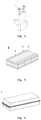
- Fig. 1 shows a secondary battery 5 with a square-shaped structure as an example.
- the external package may include a housing 51 and a cover plate 53, as shown in Fig. 4 .
- the housing 51 may include a bottom plate and side plates attached to the bottom plate. The bottom plate and the side plates are enclosed to form an accommodation chamber.
- the housing 51 has an opening communicating with the accommodation chamber, and the cover plate 53 is capable of covering the opening to close the accommodation chamber.
- the positive electrode plate, the negative electrode plate and the separator can form an electrode assembly 52 by winding or laminating process.
- the electrode assembly 52 is encapsulated in the accommodation chamber.
- the electrode assembly 52 is infiltrated by the electrolyte solution.
- the number of electrode assemblies 52 contained in the secondary battery 5 may be one or more, and may be adjusted according to requirements.
- the secondary batteries can be assembled into a battery module.
- the number of secondary batteries in the battery module can be more than one. The specific number can be adjusted according to the application and capacity of the battery module.
- Fig. 5 shows the battery module 4 as an example.
- multiple secondary batteries 5 may be arranged in sequence along the length direction of battery module 4.
- the multiple secondary batteries 5 can be fixed by fasteners.
- the battery module 4 can also include a house with the accommodation space, in which multiple secondary batteries 5 are accommodated.
- the battery modules can also be assembled into a battery pack.
- the number of battery modules contained in the battery pack can be adjusted according to the application and capacity of the battery pack.
- Figs. 6 and 7 are of the battery pack 1 as an example.
- the battery pack 1 may include a battery cabinet body and multiple battery modules 4 set in the battery cabinet body.
- the battery cabinet body comprises an upper cabinet body 2 and a lower cabinet body 3, wherein the upper cabinet body 2 is capable of covering the lower cabinet body 3 and form a closed space for accommodating the battery module 4.
- Multiple battery modules 4 can be arranged in any way in the battery cabinet body.
- the second aspect of the present application provides a process for preparing a secondary battery, including preparing a negative electrode plate of the secondary battery by the following steps:
- the secondary battery of the present application can have good low temperature rate performance and long cycle life while having higher energy density.
- the first negative electrode active material slurry and the second negative electrode active material slurry can be coated at the same time in one step, or can be coated separately.
- the first negative electrode active material slurry and second negative electrode active material slurry are simultaneously applied at one time.
- the first and second negative electrode films can be better bonded by applying together in one coating step, which may further improve the cycle performance of the battery.
- the positive plate of the present application can be prepared as follows: mixing an positive electrode active material, optional conductive agents (such as carbon materials for example carbon black) and binders (such as PVDF) and the like, dispersing the mixture into a solvent (such as NMP), uniformly stirring, coating the mixture on a positive current collector, and drying to obtain a positive plate.
- a solvent such as NMP
- Material such as aluminum foil or porous metal plate can be used as a positive electrode current collector.
- a positive tab can be obtained in the uncoated area of the positive current collector through modes of punching or laser die cutting and the like.
- the positive electrode plate, the separator and the negative electrode plate can be stacked, the separator between the positive and negative electrode plates works for isolation, and then the electrode assembly can be obtained by a winding or laminating process; the battery assembly is placed in an external package, into which the electrolyte solution is injected when it is dried. After that, the processes of vacuum packing, steady standing, formation, and shaping are carried out, thereby obtaining a secondary battery.
- the apparatus comprises a secondary battery according to the first aspect of the present application or comprises a secondary battery prepared by the process according to the second aspect of the present application.
- the secondary battery can be used as the power source of the apparatus or as the energy storage unit of the apparatus.
- the apparatus in the present application uses the secondary battery provided in the present application and thus has at least the same advantage as the secondary battery.
- the apparatus can be, but is not limited to, a mobile apparatus (such as mobile phone, laptop, etc.), an electric vehicle (such as a pure electric vehicle, hybrid electric vehicle, plug-in hybrid electric vehicle, electric bicycle, electric scooter, electric golf cart, electric truck, etc.), an electric train, a ship and satellite, an energy storage system, etc.
- a mobile apparatus such as mobile phone, laptop, etc.
- an electric vehicle such as a pure electric vehicle, hybrid electric vehicle, plug-in hybrid electric vehicle, electric bicycle, electric scooter, electric golf cart, electric truck, etc.
- an electric train such as a ship and satellite, an energy storage system, etc.
- the apparatus may be a secondary battery, battery module or battery pack according to its application requirement.
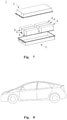
- Fig. 8 shows an apparatus as an example.
- the apparatus is may be pure electric vehicle, hybrid electric vehicle, or plug-in electric hybrid electric vehicle and so on.
- the battery pack or battery module can be used.
- the apparatus may be mobile phone, tablet PC, laptop, and the like.
- the apparatus is usually required to be lightweight and can be powered by the secondary battery.
- Lithium nickel cobalt manganese ternary active material LiNi 0.8 Co 0.1 Mn 0.1 O 2 (NCM 811), a conductive carbon black (Super-P) and a binder polyvinylidene fluoride (PVDF) in a weight ratio of 94: 3: 3 were mixed in an N-methylpyrrolidone solvent (NMP) and well stirred until homogeneous, thereby giving a slurry.
- NMP N-methylpyrrolidone solvent
- the slurry was applied on an aluminum foil substrate followed by drying, cold pressing, splitting, cutting and the like to give a positive electrode plate.
- the positive electrode film had an areal density of 17.5 mg/cm 2 and a compacted density of 3.4 g/cm 3 .
- Step one preparing negative slurry 1: natural graphite as a first negative electrode active material, SBR as a binder, sodium carboxyl methylcellulose (CMC-Na) as a thickener and a conductive carbon black (Super-P) at a weight ratio of 96.2: 1.8: 1.2: 0.8 together with deionized water were added to a stirring tank in a certain order for mixing to prepare the negative slurry 1;
- natural graphite as a first negative electrode active material
- SBR sodium carboxyl methylcellulose
- Super-P conductive carbon black
- Step two preparing negative slurry 2: artificial graphite as a second negative electrode active material, SBR as a binder, sodium carboxyl methylcellulose (CMC-Na) as a thickener, and a conductive carbon black (Super-P) at a ratio of 96.2: 1.8: 1.2: 0.8 together with deionized water were added to a stirring tank in a certain order for mixing to prepare negative slurry 2;
- SBR sodium carboxyl methylcellulose
- Super-P conductive carbon black
- Step three extruding the negative slurry 1 and negative slurry 2 at the same time through a dual-cavity coating apparatus.
- the negative slurry 1 was applied on a negative current collector to form a first negative electrode film
- the negative slurry 2 was coated on the first negative electrode film to form a second negative electrode film, wherein the mass ratio of the first negative electrode film to the second negative electrode film was 1: 1, and the whole negative electrode film had had an areal density of 11.5 mg/cm 2 and a compacted density of 1.65 g/cm 3 ;
- Step four baking the applied wet film in an oven at different temperature areas to form a dried plate, which was subjected to cold pressing to form the desired negative electrode film; after that, striping, cutting and the like were performed to give a negative electrode plate.
- PE film was selected as separator.
- Ethylene carbonate (EC), methyl ethyl carbonate (EMC) and diethyl carbonate (DEC) were mixed according to a volume ratio of 1:1:1. Then a fully dried lithium salt LiPF 6 was dissolved into the mixed organic solvent at the ratio of 1mol/L to prepare an electrolyte solution.
- the positive plate, the separator and the negative electrode plate described as above were sequentially stacked, and the stack was wound into an electrode assembly.
- the electrode assembly was packed into an outer package into which the electrolyte was added. After packaging, standing, formation, aging and the like, a secondary battery was thus obtained.
- the secondary batteries prepared in the above examples and comparative examples were subjected to a charging and discharging test including constant-current discharging the battery at a current of 1.0C (i.e., the current value at which the theoretical capacity is completely discharged within 1h) to a cut-off voltage of 2.8V, constant-current charging the battery to a charging cut-off voltage of 4.2 at a current of 1.0C, then constant-voltage charging the battery to a current of 0.05C, at which state the battery is fully charged. After the fully charged battery was allowed to stand for 5 minutes, it was discharged at a constant current of 1.0C to the discharge cut-off voltage.
- a charging and discharging test including constant-current discharging the battery at a current of 1.0C (i.e., the current value at which the theoretical capacity is completely discharged within 1h) to a cut-off voltage of 2.8V, constant-current charging the battery to a charging cut-off voltage of 4.2 at a current of 1.0C, then constant-voltage
- the discharging capacity at this state was the actual capacity of the battery at 1.0C, which was recorded as C0. Then the battery was allowed to stand for 30 minutes in an environment of -10°C, then was charged with a constant current of x C0 to the upper limit of the cut-off voltage, and then was charged with a constant voltage to current of 0.05C0. After standing 5 minutes, the battery was disassembled to observe the interface lithium precipitation. If lithium was not precipitated on the surface of the negative electrode, batteries were subjected the test at an increased charging rate again until lithium was precipitated on the surface of the negative electrode. The maximum charge rate at which no lithium was precipitated on the surface of the negative electrode was recorded to characterize the low-temperature lithium precipitation performance of batteries.
- the batteries prepared in the above examples and comparative examples were charged and discharged for the first time including constant-current and constant-voltage charging the battery at a charging current of 1.0C (i.e., the current value at which the theoretical capacity is completely discharged within 1h) to a charging cut-off voltage of 4.2, then constant-voltage discharging the battery at a discharging current of 1.0 C to a discharging cut-off voltage of 2.8V, which is a charging-discharging cycle and at which the discharging capacity is the discharging capacity for the first cycle. Subsequently, continuous charging and discharging cycles were carried, the discharge capacities after each cycle were recorded.
- the capacity retention rate of the N th cycle (discharge capacity for the N th cycle/discharge capacity for the first cycle) ⁇ 100%, the capacity retention rate of each cycle were calculated.
- the cycle capacity retention rate was equal to 80%, the number of cycles was recorded.
- the volume average particle size DV50 of natural graphite and artificial graphite also had a greater impact on battery performance.
- the volume average particle size DV50 of natural graphite was preferably in the range of 15 ⁇ m to 19 ⁇ m, more preferably from 16 ⁇ m to 18 ⁇ m; and the volume average particle size DV50 of the artificial graphite was preferably in the range of 14 ⁇ m to 18 ⁇ m, more preferably from 15 ⁇ m to 17 ⁇ m.
- the secondary battery in order to obtain secondary batteries with a better low-temperature rate performance and longer cycle life while having a higher energy density, the secondary battery should meet 0.60 ⁇ S1 ⁇ 0.85.
Landscapes
- Chemical & Material Sciences (AREA)
- Chemical Kinetics & Catalysis (AREA)
- Electrochemistry (AREA)
- General Chemical & Material Sciences (AREA)
- Engineering & Computer Science (AREA)
- Inorganic Chemistry (AREA)
- Manufacturing & Machinery (AREA)
- Materials Engineering (AREA)
- Composite Materials (AREA)
- Organic Chemistry (AREA)
- Life Sciences & Earth Sciences (AREA)
- General Life Sciences & Earth Sciences (AREA)
- Geology (AREA)
- Battery Electrode And Active Subsutance (AREA)
- Inorganic Compounds Of Heavy Metals (AREA)
- Carbon And Carbon Compounds (AREA)
Abstract
Description
- The present application belongs to the field of electrochemical technology and, more specifically, relates to a secondary battery, a process for preparing the same and an apparatuses containing the secondary battery.
- Secondary battery is widely used in various consumer electronic products and electric vehicles due to its outstanding characteristics of light weight, no pollution, and no memory effect.
- With the development of new energy industry, people put forward higher energy density for secondary batteries. However, the performance of secondary batteries puts forward higher requirements for use. Therefore, how to improve other electrochemical properties of secondary batteries on the premise of high energy density is the key challenge in the field of battery design.
- In view of this, it is necessary to provide a secondary battery which can solve the above problems.
- In view of the technical problems in the background, the present application provides a secondary battery, a process for preparing the same and an apparatus including the secondary battery, which aims at achieving both better low temperature rate performance and longer high temperature cycle life while the secondary battery has a high energy density.
- In order to achieve the above object, a first aspect of the present application provides a secondary battery, comprising a negative electrode plate, wherein the negative electrode plate comprises a negative electrode current collector and a negative electrode film, and the negative electrode film comprises a first negative electrode film and a second negative electrode film; the first negative electrode film is disposed on at least one surface of the negative electrode current collector and comprises a first negative electrode active material, and the second negative electrode film is disposed on the first negative electrode film and comprises a second negative electrode active material, the first negative electrode active material comprises natural graphite, and the first negative electrode active material satisfies: 0.60≤S1≤0.85, where S1=W2H/(W3R+W2H); and the second negative electrode active material comprises artificial graphite; in which W3R is a peak area of 101 crystal plane in a X-ray diffraction spectrum of the first negative electrode active material at a diffraction angle of 43.3±0.05°, and W2H is a peak area of 101 crystal plane in a X-ray diffraction spectrum of the first negative electrode active material at a diffraction angle of 44.5±0.05°.
- A second aspect of the present application provides a process for preparing a secondary battery, comprising preparing a negative electrode plate of the secondary battery by the following steps:
- 1) forming a first negative electrode film comprising a first negative electrode active material on at least one surface of a negative electrode current collector, wherein the first negative electrode active material comprises natural graphite and the first negative electrode active material satisfies: 0.60≤S1≤0.85, where S1=W2H/(W3R+W2H); and
- 2) forming a second negative electrode film comprising a second negative electrode active material on the first negative electrode film, wherein the second negative electrode active material comprises artificial graphite;
- A third aspect of the present application provides an apparatus comprising a secondary battery according to the first aspect of the present application or a secondary battery prepared according to the process of the second aspect of the present application.
- Over existing technologies, the present application provides at least the following beneficial effects:
- In the secondary battery according to the application, the negative electrode plate comprises a first negative electrode film and a second negative electrode film and in the first negative electrode film, a first negative electrode active material with a particular composition is set, so that the secondary battery can have better low temperature rate performance and longer high temperature cycle life on the premise of higher energy density.
-
-
Fig. 1 shows a schematic diagram of an embodiment of a secondary battery in the present application. -
Fig. 2 shows a schematic diagram of an embodiment of a negative electrode plate of a secondary battery in the present application. -
Fig. 3 shows a schematic diagram of another embodiment of a negative electrode plate of a secondary battery in the present application. -
Fig. 4 shows a decomposition diagram of an embodiment of a secondary battery in the present application. -
Fig. 5 shows a schematic diagram of an embodiment of a battery module. -
Fig. 6 shows a schematic diagram of an embodiment of a battery pack. -
Fig. 7 is an exploded diagram ofFig. 6 . -
Fig. 8 shows a schematic diagram of an embodiment of an apparatus in the present application that applies the secondary battery as a power source. - The reference signs used in the appended drawings are as follows:
- 1
- Battery pack
- 2
- Upper cabinet body
- 3
- Lower cabinet body
- 4
- Battery module
- 5
- Secondary battery
- 51
- House
- 52
- Electrode assembly
- 53
- Cover plate
- 10
- Negative electrode plate
- 101
- Negative electrode current collector
- 102
- Second negative electrode film
- 103
- First negative electrode film
- The application is further described in combination with specific embodiment as follows. It should be understood that these specific embodiments are used only to describe the application without limitation to its scope.
- For the sake of brevity, the present application explicitly describes some numerical ranges. However, any lower limit can be combined with any upper limit as an unspecified range; any lower limit can be combined with any other lower limit as an unspecified range, and any upper limit can be combined with any other upper limit as an unspecified range. Further, although not explicitly described, each point or single value between endpoints of a range is included in the range. Thus, each point or single value, as a lower limit or an upper limit, can be combined with any other point or single value or combined with any other lower or upper limit to form an unspecified range.
- In the description herein, it should be noted that, unless otherwise stated, the recitation of numerical ranges by "above" and "below" include all numbers within that range including the endpoints. The recitation of "more" in the phrase "one or more" includes two or more.
- Unless otherwise stated, the terms used in the present application have the common meaning known by technicians in this field. Unless otherwise stated, the values of the parameters mentioned in the present application may be measured by various methods commonly used in this field, for example by the methods below given in the examples of the present application.
- The first aspect of the application provides a secondary battery. The secondary battery comprises a positive electrode plate, a negative electrode plate and an electrolyte. During battery charging and discharging, active ions are intercalated and de-intercalated between positive and negative electrode plates. Electrolytes act as conducting ions between positive and negative electrode plates.
- The negative electrode plate according to the present application comprises a negative current collector and a negative electrode film, wherein the negative electrode film comprises a first negative electrode film and a second negative electrode film; the first negative electrode film is disposed on at least one surface of the negative current collector and comprises a first negative electrode active material, the second negative electrode film is disposed on the first negative electrode film and comprises a second negative electrode active material, the first negative electrode active material comprises natural graphite, and the first negative electrode active material satisfies: 0.60≤S1≤0.85, where S1=W2H/(W3R+W2H); and the second negative electrode active material comprises artificial graphite; in which W3R is a peak area of 101 crystal plane in a X-ray diffraction spectrum of the first negative electrode active material at a diffraction angle of 43.3±0.05°, and W2H is a peak area of 101 crystal plane in a X-ray diffraction spectrum of the first negative electrode active material at a diffraction angle of 44.5±0.05°.
- Since the present application uses a negative electrode film having a specific double-layer structure, and the upper and lower layers use specific negative electrode active materials, the battery can have better low-temperature rate performance under the premise of higher energy density. After research the inventors found that when the first negative electrode active material of the present application comprises natural graphite, the second negative electrode active material comprises artificial graphite, and S1 of the first negative electrode active material is controlled within the given range, active sites of upper and lower layers in the negative electrode plate are reasonably matched, which is conducive to improving rate performance of the battery. At the same time, porosities of the upper and lower layers are also reasonably optimized, which is conducive to electrolyte infiltration and improving cycle life of the battery.
- When S1 is less than 0.6, there are too many defects in the active material, and the surface activity is high, which deteriorates high temperature cycle performance of the battery. At the same time, accumulation of side reaction products caused by too many defects on the negative electrode plate will easily cause expansion of the battery core, which will cause the electrolyte to squeeze out and affect cycle life of the battery. When S1 is greater than 0.85, the surface activity of the active material is low, which deteriorates low-temperature rate performance of the battery.
- In a preferred embodiment, the first negative electrode active material satisfies 0.70≤S1≤ 0.80.
- The inventors have conducted intensive studies to find that, on the basis that the negative electrode plate according to the present application satisfies the foregoing requirements, the performance of the battery can be further improved in the event that it optionally satisfies one or more of the following requirements.
- In a preferred embodiment of the present application, the first negative electrode active material has a graphitization degree of from 95% to 98%, preferably from 96% to 97%.
- In a preferred embodiment of the present application, the second negative electrode active material has a graphitization degree of from 90% to 95%, preferably from 91% to 93%.
- In a preferred embodiment of the present application, the first negative electrode active material has a powder compaction density of from 1.85 g/cm3 to 2.1 g/cm3, preferably from 1.9 g/cm3 to 2.0 g/cm3 under a pressure of 50,000 N.
- In a preferred embodiment of the present application, the second negative electrode active material has a powder compaction density of from 1.7 g/cm3 to 1.9 g/cm3, preferably from 1.8 g/cm3 to 1.9 g/cm3 under a pressure of 50,000 N.
- In a preferred embodiment of the present application, the first negative electrode active material has a specific surface area (SSA) of from 1.6 m2/g to 2.4 m2/g, preferably from 1.8 m2/g to 2.2 m2/g.
- In a preferred embodiment of the present application, the second negative electrode active material has a specific surface area (SSA) of from 0.7 m2/g to 1.5 m2/g, preferably from 0.9 m2/g to 1.3 m2/g.
- In a preferred embodiment of the present application, the volume average particle size DV50 of the first negative electrode active material is greater than the volume average particle size DV50 of the second negative electrode active material.
- In a preferred embodiment of the present application, the volume average particle size DV50 of the first negative electrode active material is from 15 µm to 19 µm, preferably from 16 µm to 18 µm.
- In a preferred embodiment of the present application, the volume average particle size DV50 of the second negative electrode active material is from 14 µm to 18 µm, preferably from 15 µm to 17 µm.
- The inventors through research found that when the volume average particle size DV50 of the first negative electrode active material and/or the second negative electrode active material is within the given range, it is conducive to further improving the dynamic performance of the battery. At the same time, when the particle size is within the given range, the capacity difference of the upper and lower active materials can be reduced, and the risk of lithium precipitation during the battery cycle can be reduced, thereby further improving cycle performance of the battery.
- In a preferred embodiment of the present application, the natural graphite has a morphology that is one or more of spherical and quasi-spherical.
- In a preferred embodiment of the present application, the artificial graphite has a morphology that is one or more of a block shape and a sheet shape.
- In a preferred embodiment of the present application, the natural graphite is present in the first negative electrode active material in a mass percentage of ≥50%, more preferably from 80% to 100%.
- In a preferred embodiment of the present application, the artificial graphite is present in the second negative electrode active material in a mass ratio of is ≥80%, more preferably 90%-100%.
- In this application, the meanings represented by W2H and W3R are well known in the art and can be tested by methods known in the art. For example, it can be tested with an X-ray diffractometer (such as Bruker D8 Discover). Then, the value of S1 can be obtained by calculation with the formula of the present application.
- In the present application, the graphitization degree of material has a common meaning in this field and can be tested using methods already known in this field. For example the test could be performed using an X-ray diffractometer (e.g. Bruker D8 Discover). According to JIS K 0131-1996 and JB/T 4220-2011, the size of d002 can be measured, and then the graphitization degree can be calculated according to the formula G = (0.344-d002)/(0.344-0.3354) × 100%, where d002 is the interlayer spacing of graphite crystal structure in nm.
- In the present application, DV50 of the material has a meaning known in the art and can be tested using methods known in the art. It can be measured, for example, by a laser diffraction particle size distribution tester (e.g., a Malvern Mastersizer 3000) with reference to particle size laser diffraction e.g. the standard GB/T19077-2016. Dv50 refers to the corresponding particle size when the cumulative volume percentage of the material reaches 50%.
- In the present application, the power compacted density of a material has a common meaning in the art and can be tested by the method known in this field. For example, the test could be implemented with reference to GB/T 24533-2009 using an electronic pressure testing machine (such as UTM7305) as follows: putting a certain amount of powder on a special mold for compaction, setting different pressure, reading the thickness of the powder on the apparatus under different pressure, and calculating the compacted density under different pressure. In the present application, the pressure is set to be 50,000N.
- In the present application, the specific surface area (SSA) of a material has a common meaning in the art and can be tested by the method known in this field. For example, it may be tested with a nitrogen adsorption specific surface area analysis test method and calculated by a BET (Brunauer Emmett Teller) method, wherein the nitrogen adsorption specific surface area analysis test can be implemented using NOVA 2000e specific surface area and pore size analyzer of Conta Company, USA.
- In this application, the morphology of a negative electrode active material has a well-known meaning in the art, and can be tested by methods known in the art. For example, the electrode active material is stuck on a conductive adhesive, and tested with a scanning electron microscope (such as sigma300) for morphology of particles. The test can be carried out with reference to JY/T010-1996.
- It should be noted that the above-mentioned various parameter tests for the negative electrode active material can be performed by sampling and testing before coating, or can be performed by sampling and testing from the negative electrode film after cold pressing.
- When the above test samples are taken from the negative electrode film after cold pressing, as an example, they can be sampled as follows:
- (1) Firstly, a cold-pressed negative electrode film is randomly selected, and samples of the second negative electrode active material are taken by scraping powders (a blade can be used for sampling), wherein the depth of the powder scraping should not be more than the boundary between the first negative electrode film and the second negative electrode film;
- (2) Secondly, samples of the first negative electrode active material are taken. Since there may be an inter-fusion layer between the first negative electrode film and the second negative electrode film during the cold pressing process (that is, the first active material and the second active material are both present in the inter-fusion layer), the inter-fusion layer can be scraped off first before sampling the first negative electrode active material, and then the first negative electrode active material is scraped to get the samples for the accuracy of the measurement; and
- (3) The samples of the first negative electrode active material and the second negative electrode active material as collected above are placed into deionized water respectively, subjected to suction filtration followed by drying, and then the dried negative electrode active materials are sintered at a certain temperature and time (for example, at 400°C for 2h) to remove the binder and conductive carbon, giving the test samples of the first negative electrode active material and the second negative electrode active material.
- In the above sampling process, the boundary between the first negative electrode film and the second negative electrode film can be determined with the aid of an optical microscope or a scanning electron microscope.
- Both natural graphite and artificial graphite used in this application can be obtained commercially.
- In a preferred embodiment of the present application, the negative electrode film has a thickness of preferably ≥60 µm, more preferably from 65 µm to 80 µm. It should be noted that the thickness of the negative electrode film refers to the total thickness of the negative electrode film (that is, the sum of the thicknesses of the first negative electrode film and the second negative electrode film).
- In a preferred embodiment of the present application, the negative electrode film has an areal density of 10 mg/cm2≤CW≤13 mg/cm2, preferably, 10.5 mg/cm2≤CW≤11.5 mg/cm2. It should be noted that the areal density of the negative electrode film refers to the areal density of the whole negative electrode film (that is, the sum of the areal density of the first negative electrode film and the second negative electrode film).
- In a preferred embodiment of the present application, the thickness ratio of the first negative electrode film to the second negative electrode film is from 1:1.01 to 1:1.1, preferably from 1:1.02 to 1:1.06.
- When the thickness of the upper and lower layers is with the given range, it is beneficial to the formation of a gradient pore distribution in the upper and lower layers, so that the liquid phase conduction resistance of the active ions de-intercalated from the positive electrode on the surface of the negative electrode film is reduced, and the accumulation of ions on the surface layer will not cause lithium precipitation problems. At the same time, the uniform diffusion of active ions in films is beneficial to reduce polarization and further improve the dynamic performance and cycle performance of the battery.
- In the present application, the thickness of the negative electrode film can be measured with a high-qualified micrometer, for example, Mitutoyo293-100 with an accuracy of 0.1µt.
- In the present application, the respective thicknesses of the first negative electrode film and the second negative electrode film can be measured by using a scanning electron microscope (such as Zeiss sigma 300). The sample is prepared as follows: firstly, cutting the negative electrode into a certain size sample to be tested (e.g. 2cm × 2cm), fixing the negative electrode sample on a sample station by paraffin. Then the sample station is placed onto the sample holder and well fixed. An argon cross-section polisher (such as IB-19500CP) is powered on and vacuumed (to e.g. 10-4Pa), various parameters such as argon flow (such as 0.15MPa), voltage (such as 8KV) and polishing period (such as 2 hours) are set, and the sample holder is adjusted to start polishing in a swing mode. For sample testing, reference can be made to JY/T 010-1996. To ensure the accuracy of the test results, several (for example, 10) different areas in the test sample may be randomly selected for scanning and testing, and at a certain magnification (for example, 500 times), the respective thickness of the first negative electrode film and the second negative electrode film are read in the measuring areas, and then the average value of the test results from the several test areas are taken as the average thickness of the first negative electrode film and the second negative electrode film, respectively.
- In the present application, the areal density of the negative electrode film has a common meaning in this field and can be tested using methods known in this field. For example, a negative electrode plate subjected to a single-side coating and cold pressing is taken (if the negative electrode plate to be tested is subjected to a double-side coating, one side of the negative electrode film can be wiped off firstly), cut into small round disks with an area of S1, and the weight thereof is recorded as M1. Then the negative electrode film on the weighed negative electrode plate is wiped off and the negative electrode current collector is weighed again and the weight is recorded as M0. The areal density of the negative electrode film can be determined by the formula: (weight of negative electrode plate M1 - weight of negative electrode current collector MO)/S1. To ensure the accuracy of the test result, multiple (such as 10) test samples may be tested, and the average value is calculated as the test result.
- The compacted density of negative electrode film has a common meaning in this field and can be tested by methods already known in this field. For example, the areal density and thickness of negative electrode film could be obtained according to the above test methods, and the compacted density of negative electrode film is equal to areal density of negative electrode film / thickness of negative electrode film.
- In the secondary battery according to the present application, the negative electrode current collector may be a metal foil or a composite electrode current collector in which a metal material may be arranged on a polymer substrate to form the composite electrode current collector. As an example, the negative electrode current collector can be a copper foil.
- In the secondary battery of the present application, the first negative electrode film and/or the second negative electrode film generally contains a negative electrode active material, and an optional binder, an optional conductive agent, as well as other optional auxiliaries, and is generally formed by drying a negative electrode film slurry coating. The negative electrode film slurry is generally formed by dispersing the negative electrode active material and optionally a conductive agent, a binder, and the like in a solvent, such as N-methylpyrrolidone (NMP) or deionized water, with stirring uniformly. Other optional auxiliaries may be, for example, thickening and dispersing agents (e.g. sodium carboxyl methylcellulose, CMC-Na), PTC thermistor materials, and the like.
- As an example, the conductive agent may include one or more of the superconducting carbon, acetylene black, carbon black, Ketjen black, carbon dots, carbon nanotubes, graphene, and carbon nanofibers.
- As an example, the binder may include one or more of the styrene-butadiene rubber (SBR), water-based acrylic resin, polyvinylidene fluoride (PVDF), polytetrafluoroethylene (PTFE), ethylene-vinyl acetate copolymer (EVA), polyvinyl alcohol (PVA) and polyvinyl butyral (PVB).
- In the secondary battery of the present application, the first negative electrode active material and/or the second negative electrode active material may optionally include a certain amount of other common negative electrode active materials, such as one or more of soft carbon, hard carbon, silicon-based materials, tin-based materials, and lithium titanate, in addition to the specific negative electrode active material described above. The silicon-based material can be one or more selected from the elemental silicon, silicon-oxygen compound, silicon carbon complex and silicon alloy. The tin-based material can be one or more selected from elemental tin, tin oxygen compound, and tin alloys. Methods for preparing these materials are well known and these materials are commercially available. Technicians in this field can make appropriate choices based on the actual application environment.
- In the secondary battery according to the present application, the negative electrode film can be arranged on either or both of the two opposite surfaces of the negative electrode current collector.
-
Fig. 2 shows the schematic diagram of an embodiment of thenegative electrode plate 10 in the present application. Thenegative electrode plate 10 is composed of the negative electrodecurrent collector 101, the firstnegative electrode films 103 arranged on the two surfaces of the negative electrode current collector, and the secondnegative electrode films 102 arranged on the firstnegative electrode films 103. -
Fig. 3 shows the schematic diagram of another embodiment of thenegative electrode plate 10 in the present application. Thenegative electrode plate 10 is composed of the negative electrodecurrent collector 101, the firstnegative electrode film 103 arranged on one surface of the negative electrode current collector, and the secondnegative electrode film 102 arranged on the firstnegative electrode film 103. - It shall be noted that each negative electrode film parameter, such as thickness, areal density, compacted density of the negative electrode film and so on, given in the present application refers to a parameter range of a single-side film. If the negative electrode films are located on both surfaces of the negative electrode current collector, and the film parameter on either surface satisfies requirements of the present application, it should be deemed to fall within the protection scope of the present application. The ranges of the film thickness, areal density and the like mentioned in the present application refer to the parameters of the film after cold pressing used for assembly of a battery.
- In addition, in the secondary battery according to the present application, a negative electrode plate does not exclude other additional functional layers than a negative electrode film. For example, in some embodiments, the negative electrode plate of the present application further comprises a conductive primer (e.g., consisting of a conductive agent and a binder) sandwiched between the current collector and the first film and disposed on the surface of the current collector. In some other embodiments, the negative electrode plate of the present application further includes a protective cover layer covering the surface of the second film.
- In the secondary battery of the present application, the positive electrode plate comprises a positive electrode current collector and a positive electrode film arranged on at least one surface of the positive electrode current collector and comprising a positive electrode active material.
- It should be noted that the positive electrode current collector has two opposite surfaces in the direction of its thickness. The positive electrode film may be laminated on either or both of the two opposite surfaces of the positive electrode current collector.
- In the secondary battery of the present application, the positive electrode current collector may be a common metal foil or a composite electrode current collector in which a metal material can be arranged on a polymer substrate to form the composite electrode current collector. As an example, the positive electrode current collector maybe an aluminum foil.
- In the secondary battery of the present application, the positive electrode active material may include one or more of lithium transition metal oxides, lithium phosphates of olivine structure and their respective modified compounds. Examples of lithium transition metal oxides may include but are not limited to one or more of lithium cobalt oxides, lithium nickel oxides, lithium manganese oxides, lithium nickel cobalt oxides, lithium manganese cobalt oxides, lithium nickel manganese oxides, lithium nickel cobalt manganese oxides, lithium nickel cobalt aluminum oxides and their modified compounds. Examples of lithium phosphates in olivine structures may include, but may not be limited to, one or more of lithium iron phosphate, a composite of lithium iron phosphate with carbon, lithium manganese phosphate, a composite of lithium manganese phosphate with carbon, lithium iron manganese phosphate, a composite of lithium iron manganese phosphate with carbon and their modified compounds. The present application is not limited to these materials, but may also adopt other conventional and common materials that can be used as positive electrode active materials for secondary batteries.
- In some preferred embodiments, in order to further increase the energy density of the battery, the positive electrode active material may include one or more of a lithium transition metal oxide represented by formula 1 and the modified compounds thereof,
LiaNibCocMdOeAf Formula 1,
in which, 0.8≤a≤1.2, 0.5≤b<1, 0 < c < 1, 0 < d < 1, 1≤e≤2, 0≤f≤1, M is one or more selected from Mn, Al, Zr, Zn, Cu, Cr, Mg, Fe, V, Ti and B, and A is one or more selected from N, F, S, and Cl. - In the present application, the modified compounds of above-mentioned materials may be compounds obtained by doping and/or surface coating of materials for modification.
- In the secondary battery of the present application, the positive electrode film also optionally comprises a binder and/or a conductive agent.
- As an example, the binder for the positive electrode film may include one or more of polyvinylidene fluoride (PVDF) and polytetrafluoroethylene (PTFE).
- As an example, the conductive agent for the positive electrode film may include one or more of superconducting carbon, acetylene black, carbon black, Ketjen black, carbon dot, carbon nanotube, graphene and carbon nanofiber.
- Electrolytes act as conducting ions between positive and negative electrode plates. The present application has no specific limitation on the type of electrolyte, which may be selected according to requirements. For example, electrolytes may be at least one selected from solid and liquid electrolytes (i.e. electrolyte solution).
- In some embodiments, the electrolyte is an electrolyte solution. The electrolyte solution includes an electrolyte salt and a solvent.
- In some embodiments, the electrolyte salt can be one or more selected from LiPF6 (Lithium Hexafluorophosphate), LiBF4 (Lithium Tetrafluoroborate), LiClO4 (Lithium Perchlorate), LiAsF6 (Lithium Hexafluoroarsenate), LiFSI (Lithium Bisfluorosulfonimide), LiTFSI (Lithium Bis(trifluoromethanesulfonyl)imide), LiTFS (Lithium Trifluoromethanesulfonate), LiDFOB (Lithium Difluoro(oxalate)borate), LiBOB (Lithium Bis(oxalate)borate), LiPO2F2 (Lithium Difluorophosphate), LiDFOP (Lithium Difluorodioxalate phosphate) and LiTFOP (Lithium Tetrafluorooxalate phosphate).
- In some embodiments, the solvent may be one or more selected from ethylene carbonate (EC), propylene carbonate (PC), ethyl methyl carbonate (EMC), diethyl carbonate (DEC), dimethyl carbonate (DMC), dipropyl carbonate (DPC), methyl propyl carbonate (MPC), ethyl propyl carbonate (EPC), butylene carbonate (BC), fluorinated ethylene carbonate (FEC), methyl formate (MF), methyl acetate (MA), ethyl acetate (EA), propyl acetate (PA), methyl propionate (MP), ethyl propionate (EP), propyl propionate (PP), methyl butyrate (MB), ethyl butyrate (EB), 1,4-butyrolactone (GBL), sulfolane (SF), methyl sulfonyl methane (MSM), ethyl methyl sulphide (EMS), and ethyl sulfonyl ethanol (ESE).
- In some embodiments, additives are also optionally included in the electrolyte solution. For example, additives may include negative electrode film forming additives, or positive electrode film forming additives, as well as additives that can improve some performances of batteries, such as additives that improve battery overcharge performance, additives that improve high-temperature performance, and additives that improve low-temperature performance.
- Secondary batteries using electrolyte solutions, as well as some secondary batteries using solid-state electrolytes, also include a separator. The separator is arranged between the positive electrode plate and the negative electrode plate for isolation. The present application has no special limitation on the type of separator. Any common porous separator with good chemical and mechanical stability can be selected. In some embodiments, the material of the separator may be one or more selected from glass fibers, non-woven fabrics, polyethylene, and polypropylene and polyvinylidene fluoride. The separator can be either a single-layer film or a multi-layer composite film. When the separator is a multi-layer composite film, the materials of each layer may be the same or different.
- In some embodiments, an electrode assembly can be made by winding or laminating the positive electrode plate, negative electrode plate and separator.
- In some embodiments, the secondary battery may include an external package. The external package can be used to encapsulate the electrode assembly and electrolyte.
- In some embodiments, the external package of the secondary battery may be a hard shell, such as hard plastic shell, aluminum shell, and steel shell. The external package of the secondary battery can also be a soft pack, such as a bag-type soft pack. The soft pack may be made of plastics such as one or more of polypropylene (PP), polybutylene terephthalate (PBT), polybutylene succinate (PBS), and the like.
- The present application has no special limitation on the shape of the secondary battery, which may be cylindrical, square or any other arbitrary shape.
Fig. 1 shows asecondary battery 5 with a square-shaped structure as an example. - In some embodiments, the external package may include a
housing 51 and acover plate 53, as shown inFig. 4 . Thehousing 51 may include a bottom plate and side plates attached to the bottom plate. The bottom plate and the side plates are enclosed to form an accommodation chamber. Thehousing 51 has an opening communicating with the accommodation chamber, and thecover plate 53 is capable of covering the opening to close the accommodation chamber. The positive electrode plate, the negative electrode plate and the separator can form anelectrode assembly 52 by winding or laminating process. Theelectrode assembly 52 is encapsulated in the accommodation chamber. Theelectrode assembly 52 is infiltrated by the electrolyte solution. The number ofelectrode assemblies 52 contained in thesecondary battery 5 may be one or more, and may be adjusted according to requirements. - In some embodiments, the secondary batteries can be assembled into a battery module. The number of secondary batteries in the battery module can be more than one. The specific number can be adjusted according to the application and capacity of the battery module.
-
Fig. 5 shows the battery module 4 as an example. With reference toFig. 5 , in the battery module 4, multiplesecondary batteries 5 may be arranged in sequence along the length direction of battery module 4. Of course, it can also be arranged in any other ways. Further, the multiplesecondary batteries 5 can be fixed by fasteners. - Optionally, the battery module 4 can also include a house with the accommodation space, in which multiple
secondary batteries 5 are accommodated. - In some embodiments, the battery modules can also be assembled into a battery pack. The number of battery modules contained in the battery pack can be adjusted according to the application and capacity of the battery pack.
-
Figs. 6 and7 are of the battery pack 1 as an example. With reference toFig. 6 andFig. 7 , the battery pack 1 may include a battery cabinet body and multiple battery modules 4 set in the battery cabinet body. The battery cabinet body comprises anupper cabinet body 2 and alower cabinet body 3, wherein theupper cabinet body 2 is capable of covering thelower cabinet body 3 and form a closed space for accommodating the battery module 4. Multiple battery modules 4 can be arranged in any way in the battery cabinet body. - The second aspect of the present application provides a process for preparing a secondary battery, including preparing a negative electrode plate of the secondary battery by the following steps:
- 1) forming, on at least one surface of a negative electrode current collector, a first negative electrode film comprising a first negative electrode active material that comprises natural graphite and satisfies: 0.60≤S1≤0.85, where S1=W2H/(W3R+W2H); and
- 2) forming, on the first negative electrode film, a second negative electrode film comprising a second negative electrode active material that comprises artificial graphite,
- In the process of preparing the secondary battery, by controlling and adjusting the respective composition of the first negative electrode active material and the second negative electrode active material of the negative electrode, the secondary battery of the present application can have good low temperature rate performance and long cycle life while having higher energy density.
- In the process for preparing the secondary battery, the first negative electrode active material slurry and the second negative electrode active material slurry can be coated at the same time in one step, or can be coated separately.
- In some preferred embodiments, the first negative electrode active material slurry and second negative electrode active material slurry are simultaneously applied at one time. The first and second negative electrode films can be better bonded by applying together in one coating step, which may further improve the cycle performance of the battery.
- Except for the process for preparing the negative electrode plate of the present application, other configurations and preparation processes of the secondary battery according to the present application are known per se. For example, the positive plate of the present application can be prepared as follows: mixing an positive electrode active material, optional conductive agents (such as carbon materials for example carbon black) and binders (such as PVDF) and the like, dispersing the mixture into a solvent (such as NMP), uniformly stirring, coating the mixture on a positive current collector, and drying to obtain a positive plate. Material such as aluminum foil or porous metal plate can be used as a positive electrode current collector. When the positive plate is manufactured, a positive tab can be obtained in the uncoated area of the positive current collector through modes of punching or laser die cutting and the like.
- Finally, the positive electrode plate, the separator and the negative electrode plate can be stacked, the separator between the positive and negative electrode plates works for isolation, and then the electrode assembly can be obtained by a winding or laminating process; the battery assembly is placed in an external package, into which the electrolyte solution is injected when it is dried. After that, the processes of vacuum packing, steady standing, formation, and shaping are carried out, thereby obtaining a secondary battery.
- An apparatus is provided in the third aspect of the present application. The apparatus comprises a secondary battery according to the first aspect of the present application or comprises a secondary battery prepared by the process according to the second aspect of the present application. The secondary battery can be used as the power source of the apparatus or as the energy storage unit of the apparatus. The apparatus in the present application uses the secondary battery provided in the present application and thus has at least the same advantage as the secondary battery.
- The apparatus can be, but is not limited to, a mobile apparatus (such as mobile phone, laptop, etc.), an electric vehicle (such as a pure electric vehicle, hybrid electric vehicle, plug-in hybrid electric vehicle, electric bicycle, electric scooter, electric golf cart, electric truck, etc.), an electric train, a ship and satellite, an energy storage system, etc.
- The apparatus may be a secondary battery, battery module or battery pack according to its application requirement.
-
Fig. 8 shows an apparatus as an example. The apparatus is may be pure electric vehicle, hybrid electric vehicle, or plug-in electric hybrid electric vehicle and so on. To meet the requirements of the apparatus for the high rate and high energy density of secondary batteries, the battery pack or battery module can be used. - The apparatus, as another example, may be mobile phone, tablet PC, laptop, and the like. The apparatus is usually required to be lightweight and can be powered by the secondary battery.
- The beneficial effects of the present application are further described in combination with the examples as follows.
- To make the invention purpose, technical solution and beneficial technical effects of the present application clearer, the present application is further described in combination with the following examples. However, it should be understood that the examples of the present application is intended only to explain the present application, but not to restrict the present application in any way, and that examples of the present application are not limited to the examples given in the specification. The test conditions or operating conditions not specified in the examples shall be made according to normal conditions or as recommended by the material supplier.
- Lithium nickel cobalt manganese ternary active material LiNi0.8Co0.1Mn0.1O2 (NCM 811), a conductive carbon black (Super-P) and a binder polyvinylidene fluoride (PVDF) in a weight ratio of 94: 3: 3 were mixed in an N-methylpyrrolidone solvent (NMP) and well stirred until homogeneous, thereby giving a slurry. The slurry was applied on an aluminum foil substrate followed by drying, cold pressing, splitting, cutting and the like to give a positive electrode plate. The positive electrode film had an areal density of 17.5 mg/cm2 and a compacted density of 3.4 g/cm3.
- Step one, preparing negative slurry 1: natural graphite as a first negative electrode active material, SBR as a binder, sodium carboxyl methylcellulose (CMC-Na) as a thickener and a conductive carbon black (Super-P) at a weight ratio of 96.2: 1.8: 1.2: 0.8 together with deionized water were added to a stirring tank in a certain order for mixing to prepare the negative slurry 1;
- Step two, preparing negative slurry 2: artificial graphite as a second negative electrode active material, SBR as a binder, sodium carboxyl methylcellulose (CMC-Na) as a thickener, and a conductive carbon black (Super-P) at a ratio of 96.2: 1.8: 1.2: 0.8 together with deionized water were added to a stirring tank in a certain order for mixing to prepare
negative slurry 2; - Step three, extruding the negative slurry 1 and
negative slurry 2 at the same time through a dual-cavity coating apparatus. The negative slurry 1 was applied on a negative current collector to form a first negative electrode film, and thenegative slurry 2 was coated on the first negative electrode film to form a second negative electrode film, wherein the mass ratio of the first negative electrode film to the second negative electrode film was 1: 1, and the whole negative electrode film had had an areal density of 11.5 mg/cm2 and a compacted density of 1.65 g/cm3; and - Step four, baking the applied wet film in an oven at different temperature areas to form a dried plate, which was subjected to cold pressing to form the desired negative electrode film; after that, striping, cutting and the like were performed to give a negative electrode plate.
- PE film was selected as separator.
- Ethylene carbonate (EC), methyl ethyl carbonate (EMC) and diethyl carbonate (DEC) were mixed according to a volume ratio of 1:1:1. Then a fully dried lithium salt LiPF6 was dissolved into the mixed organic solvent at the ratio of 1mol/L to prepare an electrolyte solution.
- The positive plate, the separator and the negative electrode plate described as above were sequentially stacked, and the stack was wound into an electrode assembly. The electrode assembly was packed into an outer package into which the electrolyte was added. After packaging, standing, formation, aging and the like, a secondary battery was thus obtained.
- The preparation processes of secondary batteries of Examples 2 to 17 and Comparative Examples 1 to 2 were similar to those of Example 1, with the exception that the composition of negative electrode plate and product parameters were adjusted. The different product parameters for different examples are shown in Table 1 and Table 2.
- At 25°C, the secondary batteries prepared in the above examples and comparative examples were subjected to a charging and discharging test including constant-current discharging the battery at a current of 1.0C (i.e., the current value at which the theoretical capacity is completely discharged within 1h) to a cut-off voltage of 2.8V, constant-current charging the battery to a charging cut-off voltage of 4.2 at a current of 1.0C, then constant-voltage charging the battery to a current of 0.05C, at which state the battery is fully charged. After the fully charged battery was allowed to stand for 5 minutes, it was discharged at a constant current of 1.0C to the discharge cut-off voltage. The discharging capacity at this state was the actual capacity of the battery at 1.0C, which was recorded as C0. Then the battery was allowed to stand for 30 minutes in an environment of -10°C, then was charged with a constant current of x C0 to the upper limit of the cut-off voltage, and then was charged with a constant voltage to current of 0.05C0. After standing 5 minutes, the battery was disassembled to observe the interface lithium precipitation. If lithium was not precipitated on the surface of the negative electrode, batteries were subjected the test at an increased charging rate again until lithium was precipitated on the surface of the negative electrode. The maximum charge rate at which no lithium was precipitated on the surface of the negative electrode was recorded to characterize the low-temperature lithium precipitation performance of batteries.
- At 60°C, the batteries prepared in the above examples and comparative examples were charged and discharged for the first time including constant-current and constant-voltage charging the battery at a charging current of 1.0C (i.e., the current value at which the theoretical capacity is completely discharged within 1h) to a charging cut-off voltage of 4.2, then constant-voltage discharging the battery at a discharging current of 1.0 C to a discharging cut-off voltage of 2.8V, which is a charging-discharging cycle and at which the discharging capacity is the discharging capacity for the first cycle. Subsequently, continuous charging and discharging cycles were carried, the discharge capacities after each cycle were recorded. According to the capacity retention rate of the Nth cycle= (discharge capacity for the Nth cycle/discharge capacity for the first cycle)×100%, the capacity retention rate of each cycle were calculated. When the cycle capacity retention rate was equal to 80%, the number of cycles was recorded.
- In accordance with the above methods, the batteries of the examples and comparative examples were prepared, and tested for various performance parameters. The results are shown in Table 1 and Table 2 as below.
- First of all, it was shown by the data of Examples 1 to 5 and Comparative Examples 1 to 2 in Table 1 that only when the first negative electrode active material satisfied 0.60≤S1≤0.85, the secondary battery had both better low-temperature rate performance and longer cycle life. When S1 was too small, the cycle performance was poor; and when S1 was too large, the low-temperature rate performance was poor. In particular, when 0.70≤S1≤0.80, the overall performance of the secondary battery was optimal.
- In addition, it was shown by Examples 6 to 17 in Table 2 that the volume average particle size DV50 of natural graphite and artificial graphite also had a greater impact on battery performance. On the premise of satisfying 0.60≤S1≤0.85, in order to have better low-temperature rate performance and longer cycle life at the same time, the volume average particle size DV50 of natural graphite was preferably in the range of 15 µm to 19 µm, more preferably from 16µm to 18 µm; and the volume average particle size DV50 of the artificial graphite was preferably in the range of 14 µm to 18 µm, more preferably from 15 µm to 17 µm.
- According to the data in Table 1 and Table 2, it can be seen that in order to obtain secondary batteries with a better low-temperature rate performance and longer cycle life while having a higher energy density, the secondary battery should meet 0.60≤S1≤0.85.
- It should also be supplemented that according to the disclosure and guidance of the above-mentioned specifications, those skilled in the art may also make appropriate changes and modifications to the above-mentioned examples. Therefore, the present application is not limited to the specific examples disclosed and described above, and some modifications and changes to the present application fall within the scope of protection of the claims of the present application. In addition, although a number of specific terms are used in this specification, these terms are intended for convenience only and do not constitute any restriction on the present application.
Table 1 No. Type of the first negative electrode active material S1 of the first negative electrode active material Type of the second negative electrode active material Low-temperature lithium precipitation performance at -10°C High-temperature cycle number at capacity retention of 80% Ex. 1 Natural graphite 0.62 Artificial graphite 0.67C 991 Ex. 2 Natural graphite 0.67 Artificial graphite 0.63C 1133 Ex. 3 Natural graphite 0.74 Artificial graphite 0.60C 1326 Ex. 4 Natural graphite 0.79 Artificial graphite 0.55C 1378 Ex. 5 Natural graphite 0.84 Artificial graphite 0.46C 1415 CEx. 1 Natural graphite 0.55 Artificial graphite 0.42C 602 CEx. 2 Natural graphite 0.95 Artificial graphite 0.21C 990 Table 2 No. Type of the first negative electrode active material S1 of the first negative electrode active material Dv50 of the first negative electrode active material µm Type of the second negative electrode active material Dv50 of the second negative electrode active material µm Low-temperature lithium precipitation performance at -10°C High-temperature cycle number at capacity retention of 80% Ex. 6 Natural graphite 0.74 15.1 Artificial graphite 16.1 0.70C 1208 Ex. 7 Natural graphite 16.4 Artificial graphite 16.1 0.68C 1235 Ex. 8 Natural graphite 17.6 Artificial graphite 16.1 0.65C 1349 Ex. 9 Natural graphite 18.7 Artificial graphite 16.1 0.60C 1367 Ex. 10 Natural graphite 17.5 Artificial graphite 14.3 0.67C 1198 Ex. 11 Natural graphite 17.5 Artificial graphite 15.8 0.63C 1237 Ex. 12 Natural graphite 17.5 Artificial graphite 16.9 0.60C 1376 Ex. 13 Natural graphite 17.5 Artificial graphite 18.0 0.55C 1398 Ex. 14 Natural graphite 12.1 Artificial graphite 16.1 0.57C 1002 Ex. 15 Natural graphite 23.0 Artificial graphite 16.1 0.46C 1187 Ex. 16 Natural graphite 17.5 Artificial graphite 10.2 0.65C 1099 Ex. 17 Natural graphite 17.5 Artificial graphite 21.5 0.42C 1282
Claims (14)
- A secondary battery comprising a negative electrode plate, wherein the negative electrode plate comprises a negative electrode current collector and a negative electrode film, and the negative electrode film comprises a first negative electrode film and a second negative electrode film;the first negative electrode film is disposed on at least one surface of the negative electrode current collector and comprises a first negative electrode active material;the second negative electrode film is disposed on the first negative electrode film and comprises a second negative electrode active material,the first negative electrode active material comprises natural graphite and satisfies: 0.60≤S1≤0.85, where S1=W2H/(W3R+W2H); andthe second negative electrode active material comprises artificial graphite,in which W3R is a peak area of 101 crystal plane in a X-ray diffraction spectrum of the first negative electrode active material at a diffraction angle of 43.3±0.05°, and W2H is a peak area of 101 crystal plane in a X-ray diffraction spectrum of the first negative electrode active material at a diffraction angle of 44.5±0.05°.
- The secondary battery according to claim 1, wherein 0.70≤S1≤ 0.80.
- The secondary battery according to any one of claims 1 to 2, wherein a volume average particle size DV50 of the first negative electrode active material is larger than a volume average particle size DV50 of the second negative electrode active material.
- The secondary battery according to any one of claims 1 to 3, wherein the volume average particle size DV50 of the first negative electrode active material is from 15 µm to 19 µm, preferably from 16 µm to 18 µm; and/or,
the volume average particle size DV50 of the second negative electrode active material is from 14 µm-18 µm, preferably 15 µm-17 µm. - The secondary battery according to any one of claims 1 to 4, wherein the first negative electrode active material has a graphitization degree of from 95% to 98%, preferably from 96% to 97%; and/or
the second negative electrode active material has a graphitization degree of from 90% to 95%, preferably from 91% to 93%. - The secondary battery according to any one of claims 1 to 5, wherein the first negative electrode active material has a powder compaction density of from 1.85 g/cm3 to 2.1 g/cm3, preferably from 1.9 g/cm3 to 2.0 g/cm3 under a pressure of 50,000 N; and/or
the second negative electrode active material has a powder compaction density of from 1.7 g/cm3 to 1.9 g/cm3, preferably from 1.8 g/cm3 to 1.9 g/cm3 under a pressure of 50,000 N. - The secondary battery according to any one of claims 1 to 6, wherein the first negative electrode active material has a specific surface area (SSA) of from 1.6 m2/g to 2.4 m2/g, preferably from 1.8 m2/g to 2.2 m2/g; and/or
the second negative electrode active material has a specific surface area (SSA) of from 0.7 m2/g to 1.5 m2/g, preferably from 0.9 m2/g to 1.3 m2/g. - The secondary battery according to any one of claims 1 to 7, wherein the natural graphite has a morphology that is one or more of spherical and quasi-spherical; and/or
the artificial graphite has a morphology that is one or more of a block shape and a sheet shape. - The secondary battery according to any one of claims 1 to 8, wherein the natural graphite is present in the first negative electrode active material in a mass percentage of ≥50%, more preferably from 80% to 100%; and/or
the artificial graphite is present in the second negative electrode active material in a mass ratio of is ≥80%, more preferably 90%-100%. - The secondary battery according to any one of claims 1 to 9, wherein a thickness ratio of the first negative electrode film to the second negative electrode film is from 1:1.01 to 1:1.1, preferably from 1:1.02 to 1:1.06.
- The secondary battery according to any one of claims 1 to 10, wherein the negative electrode film has an areal density of 10 mg/cm2≤CW≤13 mg/cm2, preferably, 10.5 mg/cm2≤CW≤11.5 mg/cm2.
- The secondary battery according to any one of claims 1 to 11, wherein the secondary battery comprises a positive electrode plate, the positive electrode plate comprises a positive electrode current collector and a positive electrode film disposed on at least one surface of the positive electrode current collector and comprising a positive electrode active material, the positive electrode active material comprises one or more of lithium transition metal oxides, lithium phosphates of olivine structure and their respective modified compounds,
preferably, the positive electrode active material comprises one or more of a lithium transition metal oxide represented by formula 1 and the modified compounds thereof,
LiaNibCocMdOeAf Formula 1,
in which, 0.8≤a≤1.2, 0.5≤b<1, 0<c<1, 0<d<1, 1≤e≤2, 0≤f≤1, M is one or more selected from Mn, Al, Zr, Zn, Cu, Cr, Mg, Fe, V, Ti and B, and A is one or more selected from N, F, S, and Cl. - A process for preparing a secondary battery, comprising preparing a negative electrode plate of the secondary battery by the following steps:1) forming, on at least one surface of a negative electrode current collector, a first negative electrode film comprising a first negative electrode active material that comprises natural graphite and satisfies: 0.60≤S1≤0.85, where S1=W2H/(W3R+W2H); and2) forming, on the first negative electrode film, a second negative electrode film comprising a second negative electrode active material, that comprises artificial graphite, wherein W3R is a peak area of 101 crystal plane in a X-ray diffraction spectrum of the first negative electrode active material at a diffraction angle of 43.3±0.05°, and W2H is a peak area of 101 crystal plane in a X-ray diffraction spectrum of the first negative electrode active material at a diffraction angle of 44.5±0.05°.
- An apparatus, comprising the secondary battery according to any one of claims 1-12 or the secondary battery manufactured by the process according to claim 13.
Applications Claiming Priority (1)
| Application Number | Priority Date | Filing Date | Title |
|---|---|---|---|
| PCT/CN2020/088299 WO2021217585A1 (en) | 2020-04-30 | 2020-04-30 | Secondary battery, production method therefor, and device comprising same |
Publications (3)
| Publication Number | Publication Date |
|---|---|
| EP3958352A1 true EP3958352A1 (en) | 2022-02-23 |
| EP3958352A4 EP3958352A4 (en) | 2022-08-10 |
| EP3958352B1 EP3958352B1 (en) | 2023-01-25 |
Family
ID=78331675
Family Applications (1)
| Application Number | Title | Priority Date | Filing Date |
|---|---|---|---|
| EP20932863.2A Active EP3958352B1 (en) | 2020-04-30 | 2020-04-30 | Secondary battery, process for preparing the same and apparatus containing the secondary battery |
Country Status (6)
| Country | Link |
|---|---|
| US (1) | US12034153B2 (en) |
| EP (1) | EP3958352B1 (en) |
| JP (1) | JP7428800B2 (en) |
| KR (1) | KR102759580B1 (en) |
| CN (1) | CN113875048B (en) |
| WO (1) | WO2021217585A1 (en) |
Families Citing this family (6)
| Publication number | Priority date | Publication date | Assignee | Title |
|---|---|---|---|---|
| EP4525078A4 (en) * | 2022-11-25 | 2026-03-04 | Contemporary Amperex Technology Hong Kong Ltd | CARBONATE MATERIAL AND ASSOCIATED PREPARATION PROCESS, SECONDARY BATTERY INCLUDING IT, AND ELECTRICAL DEVICE |
| KR102835795B1 (en) * | 2022-11-25 | 2025-07-22 | 컨템포러리 엠퍼렉스 테크놀로지 (홍콩) 리미티드 | Carbon material and method for producing the same, and secondary battery and electric device containing the same |
| CN116435463A (en) * | 2023-05-10 | 2023-07-14 | 宁德时代新能源科技股份有限公司 | Negative electrode sheet, secondary battery and electrical device |
| CN120878772A (en) * | 2024-04-25 | 2025-10-31 | 宁德时代新能源科技股份有限公司 | Negative electrode plate, secondary battery and electricity utilization device |
| CN119852318A (en) * | 2024-08-30 | 2025-04-18 | 宁德时代新能源科技股份有限公司 | Negative electrode sheet, secondary battery, power utilization device, negative electrode active material and preparation method thereof |
| CN118970041A (en) * | 2024-10-21 | 2024-11-15 | 宁德时代新能源科技股份有限公司 | Lithium-ion battery, negative electrode sheet and power-consuming device |
Family Cites Families (24)
| Publication number | Priority date | Publication date | Assignee | Title |
|---|---|---|---|---|
| JP3069509B2 (en) * | 1995-04-10 | 2000-07-24 | 株式会社日立製作所 | Non-aqueous secondary battery and method for producing graphite powder |
| EP2352192B1 (en) * | 2008-10-31 | 2016-06-01 | Mitsubishi Chemical Corporation | Negative electrode material for nonaqueous secondary battery |
| KR101642887B1 (en) * | 2009-02-20 | 2016-07-26 | 미쓰비시 가가꾸 가부시키가이샤 | Carbon material for lithium ion secondary batteries |
| JP5457101B2 (en) * | 2009-08-05 | 2014-04-02 | パナソニック株式会社 | Nonaqueous electrolyte secondary battery |
| JP2012033376A (en) * | 2010-07-30 | 2012-02-16 | Mitsubishi Chemicals Corp | Negative electrode active material for nonaqueous secondary battery |
| KR101970023B1 (en) * | 2011-05-13 | 2019-04-17 | 미쯔비시 케미컬 주식회사 | Carbon material for non-aqueous secondary battery, anode using said carbon material, and non-aqueous secondary battery |
| CN103733391B (en) * | 2011-07-29 | 2016-05-18 | 丰田自动车株式会社 | Lithium rechargeable battery |
| JP2014086221A (en) * | 2012-10-22 | 2014-05-12 | Mitsubishi Chemicals Corp | Nonaqueous electrolyte secondary battery |
| JP6540514B2 (en) * | 2013-12-18 | 2019-07-10 | 三菱ケミカル株式会社 | Nonaqueous Electrolyte and Nonaqueous Electrolyte Secondary Battery Using the Same |
| CN103811759A (en) * | 2014-02-20 | 2014-05-21 | 深圳市贝特瑞新能源材料股份有限公司 | Modification method of natural graphite ball-milling machinery and modified natural graphite anode material |
| WO2016038692A1 (en) * | 2014-09-09 | 2016-03-17 | グラフェンプラットフォーム株式会社 | Graphite-based carbon material which is used as graphene precursor, graphene dispersion and graphene composite including same, and method for producing same |
| KR102439850B1 (en) * | 2015-08-27 | 2022-09-01 | 삼성에스디아이 주식회사 | Negative electrode active material for rechargeable lithium battery, method for preparing the same, and negative electrode and rechargeable lithium battery including same |
| KR102005779B1 (en) * | 2015-09-11 | 2019-08-01 | 주식회사 엘지화학 | Method of Manufacturing Negative Electrode for Secondary Battery Comprising Active Material Layers Having Different Particle Shape of Negative Active Material |
| KR101995373B1 (en) * | 2016-07-04 | 2019-09-24 | 주식회사 엘지화학 | Negative electrode for secondary battery |
| KR101986626B1 (en) * | 2016-08-26 | 2019-09-30 | 주식회사 엘지화학 | Anode for lithium secondary battery and lithium secondary battery comprising the same |
| KR101966144B1 (en) * | 2016-09-29 | 2019-04-05 | 주식회사 엘지화학 | Multi-layer Anode Comprising Natural Graphite and Artificial Graphite and Lithium Secondary Battery Comprising the Same |
| JP7241287B2 (en) * | 2017-07-27 | 2023-03-17 | パナソニックIpマネジメント株式会社 | Positive electrode active material and battery |
| CN109461964B (en) * | 2017-09-06 | 2021-06-08 | 宁德时代新能源科技股份有限公司 | A lithium ion secondary battery |
| CN109704323A (en) * | 2017-10-26 | 2019-05-03 | 宁德时代新能源科技股份有限公司 | Electrode material and secondary battery |
| KR102557446B1 (en) * | 2017-11-07 | 2023-07-18 | 삼성에스디아이 주식회사 | Negative electrode for rechargeable lithium battery, and rechargeable lithium battery including same |
| KR102553116B1 (en) * | 2018-01-25 | 2023-07-07 | 주식회사 엘지에너지솔루션 | Negative electrode, and lithium secondarty battery comprising the negative electrode |
| WO2020105196A1 (en) * | 2018-11-22 | 2020-05-28 | 日立化成株式会社 | Negative electrode material for lithium-ion secondary cell, method for manufacturing negative electrode material for lithium-ion secondary cell, negative electrode material slurry for lithium-ion secondary cell, negative electrode for lithium-ion secondary cell, and lithium-ion secondary cell |
| KR102657553B1 (en) * | 2019-06-27 | 2024-04-12 | 주식회사 엘지에너지솔루션 | Electrode for Lithium Secondary Battery having Specific Composition Condition and Lithium Secondary Battery Comprising the Same |
| KR102738165B1 (en) * | 2020-04-03 | 2024-12-05 | 주식회사 엘지에너지솔루션 | Anode for lithium secondary battery and secondary battery including the same |
-
2020
- 2020-04-30 WO PCT/CN2020/088299 patent/WO2021217585A1/en not_active Ceased
- 2020-04-30 JP JP2022532138A patent/JP7428800B2/en active Active
- 2020-04-30 KR KR1020227018356A patent/KR102759580B1/en active Active
- 2020-04-30 EP EP20932863.2A patent/EP3958352B1/en active Active
- 2020-04-30 CN CN202080006127.8A patent/CN113875048B/en active Active
-
2021
- 2021-12-10 US US17/547,271 patent/US12034153B2/en active Active
Also Published As
| Publication number | Publication date |
|---|---|
| US12034153B2 (en) | 2024-07-09 |
| CN113875048B (en) | 2024-01-23 |
| WO2021217585A1 (en) | 2021-11-04 |
| JP7428800B2 (en) | 2024-02-06 |
| EP3958352B1 (en) | 2023-01-25 |
| US20220102710A1 (en) | 2022-03-31 |
| EP3958352A4 (en) | 2022-08-10 |
| KR20220092941A (en) | 2022-07-04 |
| KR102759580B1 (en) | 2025-01-31 |
| CN113875048A (en) | 2021-12-31 |
| JP2023504472A (en) | 2023-02-03 |
Similar Documents
| Publication | Publication Date | Title |
|---|---|---|
| US12300810B2 (en) | Secondary battery, process for preparing the same and apparatus containing the secondary battery | |
| US12315918B2 (en) | Secondary battery, process for preparing the same and apparatus containing the secondary battery | |
| EP3958353B1 (en) | Secondary battery, process for preparing the same and apparatus containing the secondary battery | |
| EP3926713B1 (en) | Secondary battery, preparation method therefor and device comprising the secondary battery | |
| EP4064385A1 (en) | Secondary battery, manufacturing method for same, and related thereto, battery module, battery pack, and device | |
| US12034153B2 (en) | Secondary battery, process for preparing the same and apparatus containing the secondary battery | |
| US11322739B2 (en) | Secondary battery, method for manufacturing the same, and apparatus containing the same | |
| US12230810B2 (en) | Secondary battery and apparatus containing the same | |
| US20250046786A1 (en) | Secondary battery, manufacturing method therefor, and device containing secondary battery |
Legal Events
| Date | Code | Title | Description |
|---|---|---|---|
| STAA | Information on the status of an ep patent application or granted ep patent |
Free format text: STATUS: THE INTERNATIONAL PUBLICATION HAS BEEN MADE |
|
| PUAI | Public reference made under article 153(3) epc to a published international application that has entered the european phase |
Free format text: ORIGINAL CODE: 0009012 |
|
| STAA | Information on the status of an ep patent application or granted ep patent |
Free format text: STATUS: REQUEST FOR EXAMINATION WAS MADE |
|
| 17P | Request for examination filed |
Effective date: 20211116 |
|
| AK | Designated contracting states |
Kind code of ref document: A1 Designated state(s): AL AT BE BG CH CY CZ DE DK EE ES FI FR GB GR HR HU IE IS IT LI LT LU LV MC MK MT NL NO PL PT RO RS SE SI SK SM TR |
|
| A4 | Supplementary search report drawn up and despatched |
Effective date: 20220711 |
|
| RIC1 | Information provided on ipc code assigned before grant |
Ipc: H01M 4/525 20100101ALI20220705BHEP Ipc: H01M 4/02 20060101ALI20220705BHEP Ipc: H01M 10/0525 20100101ALI20220705BHEP Ipc: H01M 4/1393 20100101ALI20220705BHEP Ipc: H01M 4/36 20060101ALI20220705BHEP Ipc: H01M 4/04 20060101ALI20220705BHEP Ipc: H01M 4/587 20100101ALI20220705BHEP Ipc: H01M 4/133 20100101AFI20220705BHEP |
|
| GRAP | Despatch of communication of intention to grant a patent |
Free format text: ORIGINAL CODE: EPIDOSNIGR1 |
|
| STAA | Information on the status of an ep patent application or granted ep patent |
Free format text: STATUS: GRANT OF PATENT IS INTENDED |
|
| GRAS | Grant fee paid |
Free format text: ORIGINAL CODE: EPIDOSNIGR3 |
|
| DAV | Request for validation of the european patent (deleted) | ||
| DAX | Request for extension of the european patent (deleted) | ||
| INTG | Intention to grant announced |
Effective date: 20221124 |
|
| GRAA | (expected) grant |
Free format text: ORIGINAL CODE: 0009210 |
|
| STAA | Information on the status of an ep patent application or granted ep patent |
Free format text: STATUS: THE PATENT HAS BEEN GRANTED |
|
| AK | Designated contracting states |
Kind code of ref document: B1 Designated state(s): AL AT BE BG CH CY CZ DE DK EE ES FI FR GB GR HR HU IE IS IT LI LT LU LV MC MK MT NL NO PL PT RO RS SE SI SK SM TR |
|
| REG | Reference to a national code |
Ref country code: GB Ref legal event code: FG4D |
|
| REG | Reference to a national code |
Ref country code: CH Ref legal event code: EP |
|
| REG | Reference to a national code |
Ref country code: DE Ref legal event code: R096 Ref document number: 602020007899 Country of ref document: DE |
|
| REG | Reference to a national code |
Ref country code: AT Ref legal event code: REF Ref document number: 1546452 Country of ref document: AT Kind code of ref document: T Effective date: 20230215 Ref country code: IE Ref legal event code: FG4D |
|
| REG | Reference to a national code |
Ref country code: LT Ref legal event code: MG9D |
|
| REG | Reference to a national code |
Ref country code: NL Ref legal event code: MP Effective date: 20230125 |
|
| REG | Reference to a national code |
Ref country code: AT Ref legal event code: MK05 Ref document number: 1546452 Country of ref document: AT Kind code of ref document: T Effective date: 20230125 |
|
| P01 | Opt-out of the competence of the unified patent court (upc) registered |
Effective date: 20230516 |
|
| PG25 | Lapsed in a contracting state [announced via postgrant information from national office to epo] |
Ref country code: NL Free format text: LAPSE BECAUSE OF FAILURE TO SUBMIT A TRANSLATION OF THE DESCRIPTION OR TO PAY THE FEE WITHIN THE PRESCRIBED TIME-LIMIT Effective date: 20230125 |
|
| PG25 | Lapsed in a contracting state [announced via postgrant information from national office to epo] |
Ref country code: RS Free format text: LAPSE BECAUSE OF FAILURE TO SUBMIT A TRANSLATION OF THE DESCRIPTION OR TO PAY THE FEE WITHIN THE PRESCRIBED TIME-LIMIT Effective date: 20230125 Ref country code: PT Free format text: LAPSE BECAUSE OF FAILURE TO SUBMIT A TRANSLATION OF THE DESCRIPTION OR TO PAY THE FEE WITHIN THE PRESCRIBED TIME-LIMIT Effective date: 20230525 Ref country code: NO Free format text: LAPSE BECAUSE OF FAILURE TO SUBMIT A TRANSLATION OF THE DESCRIPTION OR TO PAY THE FEE WITHIN THE PRESCRIBED TIME-LIMIT Effective date: 20230425 Ref country code: LV Free format text: LAPSE BECAUSE OF FAILURE TO SUBMIT A TRANSLATION OF THE DESCRIPTION OR TO PAY THE FEE WITHIN THE PRESCRIBED TIME-LIMIT Effective date: 20230125 Ref country code: LT Free format text: LAPSE BECAUSE OF FAILURE TO SUBMIT A TRANSLATION OF THE DESCRIPTION OR TO PAY THE FEE WITHIN THE PRESCRIBED TIME-LIMIT Effective date: 20230125 Ref country code: HR Free format text: LAPSE BECAUSE OF FAILURE TO SUBMIT A TRANSLATION OF THE DESCRIPTION OR TO PAY THE FEE WITHIN THE PRESCRIBED TIME-LIMIT Effective date: 20230125 Ref country code: ES Free format text: LAPSE BECAUSE OF FAILURE TO SUBMIT A TRANSLATION OF THE DESCRIPTION OR TO PAY THE FEE WITHIN THE PRESCRIBED TIME-LIMIT Effective date: 20230125 Ref country code: AT Free format text: LAPSE BECAUSE OF FAILURE TO SUBMIT A TRANSLATION OF THE DESCRIPTION OR TO PAY THE FEE WITHIN THE PRESCRIBED TIME-LIMIT Effective date: 20230125 |
|
| PG25 | Lapsed in a contracting state [announced via postgrant information from national office to epo] |
Ref country code: SE Free format text: LAPSE BECAUSE OF FAILURE TO SUBMIT A TRANSLATION OF THE DESCRIPTION OR TO PAY THE FEE WITHIN THE PRESCRIBED TIME-LIMIT Effective date: 20230125 Ref country code: PL Free format text: LAPSE BECAUSE OF FAILURE TO SUBMIT A TRANSLATION OF THE DESCRIPTION OR TO PAY THE FEE WITHIN THE PRESCRIBED TIME-LIMIT Effective date: 20230125 Ref country code: IS Free format text: LAPSE BECAUSE OF FAILURE TO SUBMIT A TRANSLATION OF THE DESCRIPTION OR TO PAY THE FEE WITHIN THE PRESCRIBED TIME-LIMIT Effective date: 20230525 Ref country code: GR Free format text: LAPSE BECAUSE OF FAILURE TO SUBMIT A TRANSLATION OF THE DESCRIPTION OR TO PAY THE FEE WITHIN THE PRESCRIBED TIME-LIMIT Effective date: 20230426 Ref country code: FI Free format text: LAPSE BECAUSE OF FAILURE TO SUBMIT A TRANSLATION OF THE DESCRIPTION OR TO PAY THE FEE WITHIN THE PRESCRIBED TIME-LIMIT Effective date: 20230125 |
|
| REG | Reference to a national code |
Ref country code: DE Ref legal event code: R097 Ref document number: 602020007899 Country of ref document: DE |
|
| PG25 | Lapsed in a contracting state [announced via postgrant information from national office to epo] |
Ref country code: SM Free format text: LAPSE BECAUSE OF FAILURE TO SUBMIT A TRANSLATION OF THE DESCRIPTION OR TO PAY THE FEE WITHIN THE PRESCRIBED TIME-LIMIT Effective date: 20230125 Ref country code: RO Free format text: LAPSE BECAUSE OF FAILURE TO SUBMIT A TRANSLATION OF THE DESCRIPTION OR TO PAY THE FEE WITHIN THE PRESCRIBED TIME-LIMIT Effective date: 20230125 Ref country code: EE Free format text: LAPSE BECAUSE OF FAILURE TO SUBMIT A TRANSLATION OF THE DESCRIPTION OR TO PAY THE FEE WITHIN THE PRESCRIBED TIME-LIMIT Effective date: 20230125 Ref country code: DK Free format text: LAPSE BECAUSE OF FAILURE TO SUBMIT A TRANSLATION OF THE DESCRIPTION OR TO PAY THE FEE WITHIN THE PRESCRIBED TIME-LIMIT Effective date: 20230125 Ref country code: CZ Free format text: LAPSE BECAUSE OF FAILURE TO SUBMIT A TRANSLATION OF THE DESCRIPTION OR TO PAY THE FEE WITHIN THE PRESCRIBED TIME-LIMIT Effective date: 20230125 |
|
| PG25 | Lapsed in a contracting state [announced via postgrant information from national office to epo] |
Ref country code: SK Free format text: LAPSE BECAUSE OF FAILURE TO SUBMIT A TRANSLATION OF THE DESCRIPTION OR TO PAY THE FEE WITHIN THE PRESCRIBED TIME-LIMIT Effective date: 20230125 |
|
| REG | Reference to a national code |
Ref country code: CH Ref legal event code: PL |
|
| PLBE | No opposition filed within time limit |
Free format text: ORIGINAL CODE: 0009261 |
|
| STAA | Information on the status of an ep patent application or granted ep patent |
Free format text: STATUS: NO OPPOSITION FILED WITHIN TIME LIMIT |
|
| PG25 | Lapsed in a contracting state [announced via postgrant information from national office to epo] |
Ref country code: LU Free format text: LAPSE BECAUSE OF NON-PAYMENT OF DUE FEES Effective date: 20230430 |
|
| 26N | No opposition filed |
Effective date: 20231026 |
|
| REG | Reference to a national code |
Ref country code: BE Ref legal event code: MM Effective date: 20230430 |
|
| PG25 | Lapsed in a contracting state [announced via postgrant information from national office to epo] |
Ref country code: MC Free format text: LAPSE BECAUSE OF FAILURE TO SUBMIT A TRANSLATION OF THE DESCRIPTION OR TO PAY THE FEE WITHIN THE PRESCRIBED TIME-LIMIT Effective date: 20230125 |
|
| PG25 | Lapsed in a contracting state [announced via postgrant information from national office to epo] |
Ref country code: SI Free format text: LAPSE BECAUSE OF FAILURE TO SUBMIT A TRANSLATION OF THE DESCRIPTION OR TO PAY THE FEE WITHIN THE PRESCRIBED TIME-LIMIT Effective date: 20230125 Ref country code: MC Free format text: LAPSE BECAUSE OF FAILURE TO SUBMIT A TRANSLATION OF THE DESCRIPTION OR TO PAY THE FEE WITHIN THE PRESCRIBED TIME-LIMIT Effective date: 20230125 Ref country code: LI Free format text: LAPSE BECAUSE OF NON-PAYMENT OF DUE FEES Effective date: 20230430 Ref country code: CH Free format text: LAPSE BECAUSE OF NON-PAYMENT OF DUE FEES Effective date: 20230430 |
|
| REG | Reference to a national code |
Ref country code: IE Ref legal event code: MM4A |
|
| PG25 | Lapsed in a contracting state [announced via postgrant information from national office to epo] |
Ref country code: BE Free format text: LAPSE BECAUSE OF NON-PAYMENT OF DUE FEES Effective date: 20230430 |
|
| PG25 | Lapsed in a contracting state [announced via postgrant information from national office to epo] |
Ref country code: IE Free format text: LAPSE BECAUSE OF NON-PAYMENT OF DUE FEES Effective date: 20230430 |
|
| PG25 | Lapsed in a contracting state [announced via postgrant information from national office to epo] |
Ref country code: IE Free format text: LAPSE BECAUSE OF NON-PAYMENT OF DUE FEES Effective date: 20230430 |
|
| PG25 | Lapsed in a contracting state [announced via postgrant information from national office to epo] |
Ref country code: IT Free format text: LAPSE BECAUSE OF FAILURE TO SUBMIT A TRANSLATION OF THE DESCRIPTION OR TO PAY THE FEE WITHIN THE PRESCRIBED TIME-LIMIT Effective date: 20230125 |
|
| REG | Reference to a national code |
Ref country code: DE Ref legal event code: R081 Ref document number: 602020007899 Country of ref document: DE Owner name: CONTEMPORARY AMPEREX TECHNOLOGY (HONG KONG) LI, HK Free format text: FORMER OWNER: CONTEMPORARY AMPEREX TECHNOLOGY CO., LIMITED, NINGDE CITY, FUJIAN, CN |
|
| REG | Reference to a national code |
Ref country code: GB Ref legal event code: 732E Free format text: REGISTERED BETWEEN 20240815 AND 20240821 |
|
| PG25 | Lapsed in a contracting state [announced via postgrant information from national office to epo] |
Ref country code: BG Free format text: LAPSE BECAUSE OF FAILURE TO SUBMIT A TRANSLATION OF THE DESCRIPTION OR TO PAY THE FEE WITHIN THE PRESCRIBED TIME-LIMIT Effective date: 20230125 |
|
| PG25 | Lapsed in a contracting state [announced via postgrant information from national office to epo] |
Ref country code: BG Free format text: LAPSE BECAUSE OF FAILURE TO SUBMIT A TRANSLATION OF THE DESCRIPTION OR TO PAY THE FEE WITHIN THE PRESCRIBED TIME-LIMIT Effective date: 20230125 |
|
| PGFP | Annual fee paid to national office [announced via postgrant information from national office to epo] |
Ref country code: DE Payment date: 20250305 Year of fee payment: 6 |
|
| PG25 | Lapsed in a contracting state [announced via postgrant information from national office to epo] |
Ref country code: CY Free format text: LAPSE BECAUSE OF FAILURE TO SUBMIT A TRANSLATION OF THE DESCRIPTION OR TO PAY THE FEE WITHIN THE PRESCRIBED TIME-LIMIT; INVALID AB INITIO Effective date: 20200430 |
|
| PG25 | Lapsed in a contracting state [announced via postgrant information from national office to epo] |
Ref country code: HU Free format text: LAPSE BECAUSE OF FAILURE TO SUBMIT A TRANSLATION OF THE DESCRIPTION OR TO PAY THE FEE WITHIN THE PRESCRIBED TIME-LIMIT; INVALID AB INITIO Effective date: 20200430 |
|
| PG25 | Lapsed in a contracting state [announced via postgrant information from national office to epo] |
Ref country code: TR Free format text: LAPSE BECAUSE OF FAILURE TO SUBMIT A TRANSLATION OF THE DESCRIPTION OR TO PAY THE FEE WITHIN THE PRESCRIBED TIME-LIMIT Effective date: 20230125 |
|
| PGFP | Annual fee paid to national office [announced via postgrant information from national office to epo] |
Ref country code: GB Payment date: 20260310 Year of fee payment: 7 |
|
| PGFP | Annual fee paid to national office [announced via postgrant information from national office to epo] |
Ref country code: FR Payment date: 20260309 Year of fee payment: 7 |