EP3958347A1 - Electrode for secondary battery and method for manufacturing electrode for secondary battery - Google Patents
Electrode for secondary battery and method for manufacturing electrode for secondary battery Download PDFInfo
- Publication number
- EP3958347A1 EP3958347A1 EP20897342.0A EP20897342A EP3958347A1 EP 3958347 A1 EP3958347 A1 EP 3958347A1 EP 20897342 A EP20897342 A EP 20897342A EP 3958347 A1 EP3958347 A1 EP 3958347A1
- Authority
- EP
- European Patent Office
- Prior art keywords
- electrode
- uncoated portion
- secondary battery
- residual stress
- current collector
- Prior art date
- Legal status (The legal status is an assumption and is not a legal conclusion. Google has not performed a legal analysis and makes no representation as to the accuracy of the status listed.)
- Pending
Links
Images


Classifications
-
- B—PERFORMING OPERATIONS; TRANSPORTING
- B24—GRINDING; POLISHING
- B24C—ABRASIVE OR RELATED BLASTING WITH PARTICULATE MATERIAL
- B24C1/00—Methods for use of abrasive blasting for producing particular effects; Use of auxiliary equipment in connection with such methods
- B24C1/10—Methods for use of abrasive blasting for producing particular effects; Use of auxiliary equipment in connection with such methods for compacting surfaces, e.g. shot-peening
-
- H—ELECTRICITY
- H01—ELECTRIC ELEMENTS
- H01M—PROCESSES OR MEANS, e.g. BATTERIES, FOR THE DIRECT CONVERSION OF CHEMICAL ENERGY INTO ELECTRICAL ENERGY
- H01M4/00—Electrodes
- H01M4/02—Electrodes composed of, or comprising, active material
- H01M4/04—Processes of manufacture in general
- H01M4/043—Processes of manufacture in general involving compressing or compaction
- H01M4/0435—Rolling or calendering
-
- C—CHEMISTRY; METALLURGY
- C21—METALLURGY OF IRON
- C21D—MODIFYING THE PHYSICAL STRUCTURE OF FERROUS METALS; GENERAL DEVICES FOR HEAT TREATMENT OF FERROUS OR NON-FERROUS METALS OR ALLOYS; MAKING METAL MALLEABLE, e.g. BY DECARBURISATION OR TEMPERING
- C21D7/00—Modifying the physical properties of iron or steel by deformation
- C21D7/02—Modifying the physical properties of iron or steel by deformation by cold working
- C21D7/04—Modifying the physical properties of iron or steel by deformation by cold working of the surface
- C21D7/06—Modifying the physical properties of iron or steel by deformation by cold working of the surface by shot-peening or the like
-
- H—ELECTRICITY
- H01—ELECTRIC ELEMENTS
- H01M—PROCESSES OR MEANS, e.g. BATTERIES, FOR THE DIRECT CONVERSION OF CHEMICAL ENERGY INTO ELECTRICAL ENERGY
- H01M4/00—Electrodes
- H01M4/02—Electrodes composed of, or comprising, active material
- H01M4/04—Processes of manufacture in general
- H01M4/0402—Methods of deposition of the material
- H01M4/0404—Methods of deposition of the material by coating on electrode collectors
-
- H—ELECTRICITY
- H01—ELECTRIC ELEMENTS
- H01M—PROCESSES OR MEANS, e.g. BATTERIES, FOR THE DIRECT CONVERSION OF CHEMICAL ENERGY INTO ELECTRICAL ENERGY
- H01M4/00—Electrodes
- H01M4/02—Electrodes composed of, or comprising, active material
- H01M4/04—Processes of manufacture in general
- H01M4/043—Processes of manufacture in general involving compressing or compaction
-
- H—ELECTRICITY
- H01—ELECTRIC ELEMENTS
- H01M—PROCESSES OR MEANS, e.g. BATTERIES, FOR THE DIRECT CONVERSION OF CHEMICAL ENERGY INTO ELECTRICAL ENERGY
- H01M4/00—Electrodes
- H01M4/02—Electrodes composed of, or comprising, active material
- H01M4/64—Carriers or collectors
- H01M4/66—Selection of materials
- H01M4/665—Composites
- H01M4/667—Composites in the form of layers, e.g. coatings
-
- H—ELECTRICITY
- H01—ELECTRIC ELEMENTS
- H01M—PROCESSES OR MEANS, e.g. BATTERIES, FOR THE DIRECT CONVERSION OF CHEMICAL ENERGY INTO ELECTRICAL ENERGY
- H01M10/00—Secondary cells; Manufacture thereof
- H01M10/04—Construction or manufacture in general
- H01M10/0431—Cells with wound or folded electrodes
-
- H—ELECTRICITY
- H01—ELECTRIC ELEMENTS
- H01M—PROCESSES OR MEANS, e.g. BATTERIES, FOR THE DIRECT CONVERSION OF CHEMICAL ENERGY INTO ELECTRICAL ENERGY
- H01M10/00—Secondary cells; Manufacture thereof
- H01M10/05—Accumulators with non-aqueous electrolyte
- H01M10/058—Construction or manufacture
- H01M10/0587—Construction or manufacture of accumulators having only wound construction elements, i.e. wound positive electrodes, wound negative electrodes and wound separators
-
- H—ELECTRICITY
- H01—ELECTRIC ELEMENTS
- H01M—PROCESSES OR MEANS, e.g. BATTERIES, FOR THE DIRECT CONVERSION OF CHEMICAL ENERGY INTO ELECTRICAL ENERGY
- H01M10/00—Secondary cells; Manufacture thereof
- H01M10/42—Methods or arrangements for servicing or maintenance of secondary cells or secondary half-cells
- H01M10/4235—Safety or regulating additives or arrangements in electrodes, separators or electrolyte
-
- H—ELECTRICITY
- H01—ELECTRIC ELEMENTS
- H01M—PROCESSES OR MEANS, e.g. BATTERIES, FOR THE DIRECT CONVERSION OF CHEMICAL ENERGY INTO ELECTRICAL ENERGY
- H01M4/00—Electrodes
- H01M4/02—Electrodes composed of, or comprising, active material
- H01M4/04—Processes of manufacture in general
- H01M4/0471—Processes of manufacture in general involving thermal treatment, e.g. firing, sintering, backing particulate active material, thermal decomposition, pyrolysis
-
- Y—GENERAL TAGGING OF NEW TECHNOLOGICAL DEVELOPMENTS; GENERAL TAGGING OF CROSS-SECTIONAL TECHNOLOGIES SPANNING OVER SEVERAL SECTIONS OF THE IPC; TECHNICAL SUBJECTS COVERED BY FORMER USPC CROSS-REFERENCE ART COLLECTIONS [XRACs] AND DIGESTS
- Y02—TECHNOLOGIES OR APPLICATIONS FOR MITIGATION OR ADAPTATION AGAINST CLIMATE CHANGE
- Y02E—REDUCTION OF GREENHOUSE GAS [GHG] EMISSIONS, RELATED TO ENERGY GENERATION, TRANSMISSION OR DISTRIBUTION
- Y02E60/00—Enabling technologies; Technologies with a potential or indirect contribution to GHG emissions mitigation
- Y02E60/10—Energy storage using batteries
Definitions
- the present disclosure relates to an electrode for a secondary battery and a method of manufacturing the electrode for a secondary battery, and more particularly, to a rolling device and a rolling method for a secondary battery that enhances a resistance against stress of non-coated portion.
- the secondary battery can be formed by inserting an electrode assembly composed of a positive electrode plate, a negative electrode plate, and a separator into a case, and then sealing the can.
- a positive electrode plate or a negative electrode plate (hereinafter, referred to as "electrode plate”) can be configured by coating an active material slurry onto a positive conductive current collector or a negative conductive current collector to a predetermined thickness, interposing a separator between the positive electrode conductive current collector and the negative electrode conductive current collector, and winding the plate in a jelly-roll type many times or laminating it in a plurality of layers to form an electrode assembly.
- the electrode plate may be formed of an active material coating layer coated with an active material slurry and a non-coated portion.
- the active material coating layer can include a roll process for increasing the adhesiveness to the electrode current collector and increasing the volume density of the active material.
- the rolled electrode plate can, after drying, be used by being passed through a cutter having a certain width and cut into a predetermined size.
- the roll process has a problem that a compression deviation occurs due to a difference in thickness between the coating layer and the non-coated portion at the time of rolling the electrode plate. Due to such a deviation, unbalanced plastic deformation of the electrode current collector may occur, thereby causing a residual stress. In particular, the tensile residual stress may cause a reduction of fatigue durability and a reduction of fracture strength of components.
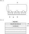
- FIG. 1 is a schematic diagram showing a roll process using a conventional rolling device.
- FIG. 2 is a plan view showing an electrode plate after rolling.
- a roll process of rolling a coated layer 30 and a non-coated portion 40 formed on an electrode current collector 20 by a rolling roll 10 may be performed.
- the pressure is concentrated on the coated layer 30, and as shown in FIG. 2 , a difference occurs between the degree of stretching of the coated portion 30P and the degree of stretching of the non-coated portion 40, and wrinkles may be generated in the non-coated portion 40. Due to the wrinkles of the non-coated portion 40 generated during rolling, process defects such as electrode disconnection may occur in a subsequent process.
- a high tensile residual stress remains at a boundary surface between the coated portion 30P and the non-coated portion 40, they can continuously receive weak stress due to the contraction and expansion of the electrode, and may become vulnerable to fracture.
- a method of manufacturing an electrode for a secondary battery comprising the steps of: coating an active material onto an electrode current collector to form a coated portion and an uncoated portion, and applying a compressive residual stress to the surface of the uncoated portion, wherein the step of applying the compressive residual stress to the surface of the uncoated portion comprises a step of performing a peening process on the surface of the uncoated portion.
- the step of applying the compressive residual stress to the surface of the uncoated portion is performed before a roll process performed along the moving direction of the electrode current collector, and the roll process may include at least one of a process of rolling a coated portion and an uncoated portion of the electrode current collector and a process of notching a coated portion and an uncoated portion of the electrode current collector.
- the step of applying the compressive residual stress to the surface of the uncoated portion may include a step of performing a shot peening process.
- the step of performing a shot peening process may include a step of forming a dimple portion on the surface of the uncoated portion.
- a plastic deformation layer is formed on the surface of the dimple portion, so that the plastic deformation layer has a residual compressive stress, and the inside of the uncoated portion located outside the plastic deformation layer has a tensile residual stress.
- the step of applying the compressive residual stress to the surface of the uncoated portion may include a step of performing an ultrasonic peening process.
- the step of performing an ultrasonic peening process may include a step of forming a dimple portion on the surface of the uncoated portion.
- the method of manufacturing an electrode for a secondary battery may further include a step of heat-treating the electrode current collector, after the step of performing a peening process on the surface of the uncoated portion.
- an electrode for a secondary battery comprising: an electrode current collector including a coated portion and an uncoated portion, and an active material layer located on the coated portion of the electrode current collector, wherein a dimple portion is formed on the surface of the uncoated portion, and a plastic deformation layer is formed on the surface of the dimple portion.
- the electrode for a secondary battery further includes a plastic deformation layer located on the surface of the dimple portion, wherein the plastic deformation layer may have a compressive residual stress, and the inside of the uncoated portion located outside the plastic deformation layer has a tensile residual stress.
- the fatigue durability and fracture strength of the material can be improved and the resistance against stress can be enhanced. Therefore, it is possible to reduce the occurrence of fracture due to fatigue fracture at the boundary surface between the electrode and the uncoated portion.
- planar when referred to as “planar”, it means when a target portion is viewed from the upper side, and when referred to as “cross-sectional”, it means when a target portion is viewed from the side of a cross section cut vertically.
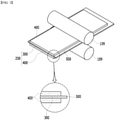
- FIG. 3 is a perspective view showing a rolling device according to one embodiment of the present disclosure.
- a method of manufacturing an electrode for a secondary battery includes the steps of: coating an active material onto an electrode current collector 300 to form a coated portion 400 and an uncoated portion 500, and applying a compressive residual stress to the surface of the uncoated portion 500.
- the step of applying the compressive residual stress to the surface of the uncoated portion 500 includes a step of performing a peening process on the surface of the uncoated portion 500. When performing a peening process on the surface of the uncoated portion 500, it is desirable to minimize a physical deformation on the surface of the uncoated portion 500.
- a compressive residual stress must be applied to the surface of the uncoated portion 500 by an action such as quenching through a peening process, which is different from applying an elongation force.
- an action such as quenching through a peening process, which is different from applying an elongation force.
- the step of applying a compressive residual stress to the surface of the uncoated portion 500 is performed before a roll process performed along the moving direction of the electrode current collector 300, and the roll process may include at least one of a process of rolling a coated portion 400 and an uncoated portion 500 of the electrode current collector 300 and a process of notching a coated portion 400 and an uncoated portion 500 of the electrode current collector 300.
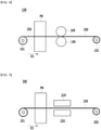
- FIG. 4 is a diagram schematically showing a state in which the rolling device of FIG. 3 is viewed from the front.
- FIG. 5 is a schematic diagram showing a notching device according to one embodiment of the present disclosure.
- the electrode rolling device 100 includes a first roller 101 which unwinds an electrode plate 250 having a coated portion 400 on which a coating material is formed on the electrode current collector 300 and an uncoated portion 500 corresponding to a non-coated portion, a second roller 102 which winds the electrode plate 250, and a rolling roll 109 which is located between the first roller 101 and the second roller 102 and rolls the coated portion 400 and the uncoated portion 500 of the electrode plate 250 along the moving direction of the electrode plate 250.
- the uncoated portion 500 may refer to a region excluding the coated portion 400 formed on the electrode current collector 300.
- the first roller 101 provides the electrode plate 250 to be rolled to the rolling device 100, and moves the electrode plate 250 in a direction of arrow D1 of FIG. 4 in accordance with the clockwise rotation.
- the electrode plate 250 unwound by the first roller 101 passes between the rolling rolls 109 while moving along the direction of the arrow.
- the rolling rolls 109 are located on both sides with respect to the electrode plate 250, respectively, and the electrode plate 250 that has passed between the two rolling rolls 109 is pressed. After that, the electrode plate 250 that has passed between the two rolling rolls 109 is rewound on the second roller 102.
- the method of manufacturing an electrode for a secondary battery according to the embodiment of the present disclosure includes a step of performing a peening process, before the electrode plate 250 having the coated portion 400 and the uncoated portion 500 is unwinded and then rolled by the rolling roll 109.
- the peening process may be performed by a peening device PN located between the first roller 101 and the rolling roll 109 in the electrode rolling device 100 according to this embodiment.
- the peening process may apply a compressive residual stress to the uncoated portion 500 according to this embodiment.
- the method of manufacturing an electrode for a secondary battery according to the embodiment of the present disclosure includes a step of performing a shot peening process, before the electrode plate 250 having the coated portion 400 and the uncoated portion 500 is unwinded and then notched by an upper mold 210 and a lower mold 220 for notching.
- the peening process may be performed by a peening device PN located between the first roller 201 and the notching molds 210 and 220 in the electrode notching device 200 according to the present embodiment.
- FIG. 6 is a schematic cross-sectional view showing a peening process of FIGS. 4 and 5 .
- FIG. 7 is a perspective view showing a shot peening process according to an embodiment of the present disclosure.
- FIG. 8 is a cross-sectional view showing a state in which a dimple portion is formed by shot peening of FIG. 7 .
- the step of applying a compressive residual stress to the surface of the uncoated portion 500 may include a step of performing a shot peening process or a step of performing an ultrasonic peening process.
- the step of performing the shot peening process will be mainly described.
- a shot ball 600 may be thrown onto the surface of the uncoated portion 500 at high speed to hammer the surface of the electrode current collector 300.
- the shot ball 600 may be formed of a steel ball such as stainless steel.
- the shot ball 600 collides with the surface of the uncoated portion 500 at high speed, and a kinetic energy of the shot ball 600 instantaneously causes a plastic deformation on the surface of the material, and the shot ball 600 separates from the surface.
- the uncoated portion 500 is formed with a dimple portion DP having an indented shape.
- a thin plastic deformation layer PDL is formed on the surface of the dimple portion DP, and the plastic deformation layer PDL may have a compressive residual stress.
- the inside of the uncoated portion 500 located outside the plastic deformation layer PDL may have a tensile residual stress.
- the compressive residual stress and tensile residual stress described above can be interpreted as cosine values of the residual stress measured using a residual stress tester.
- the step of applying a compressive residual stress to the surface of the uncoated portion 500 may include a step of performing an ultrasonic peening process.
- an ultrasonic device 700 is disposed on the upper end of the uncoated part 500, so that ultrasonic waves collide with the surface of the uncoated part 500 at high speed, thereby causing plastic deformation.
- the compressive residual stress can be controlled while ultrasonic energy is transmitted to the surface of the uncoated portion 500, and high and low cycle fatigue can be improved.
- the ultrasonic peening process may be performed while controlling the altitude of the ultrasonic device 700 shown in FIG. 6 . Through such an altitude control, the surface roughness of the uncoated portion 500 may be controlled.
- the step of performing an ultrasonic peening process may replace the step of performing the above-described shot peening process.
- a dimple portion may be formed on the surface of the uncoated portion 500, and a plastic deformation layer having a compressive residual stress is formed on the surface of the dimple portion, and the inside of the uncoated portion located outside the plastic deformation layer may have a tensile residual stress.
- the physical deformation on the surface of the uncoated portion 500 may be relatively small compared to the above-described shot peening.
- FIG. 9 is a schematic cross-sectional view showing an aging process according to an embodiment of the present disclosure.
- the method of manufacturing an electrode for a secondary battery may include a step of heat-treating the electrode current collector 300 after performing a peening process on the surface of the uncoated portion 500.
- a heat treatment apparatus 800 is disposed on the upper end of the uncoated part 500 so that ultrasonic waves collide with the surface of the uncoated part 500 at high speed, thereby causing plastic deformation.
- a compressive residual stress may be further generated on the surface of the electrode current collector 300. Accordingly, the level at which unbalanced plastic deformation occurs due to stress during rolling can be alleviated, and the level of tensile residual stress generated on the surface can be significantly alleviated.
- the electrode current collector 300 by applying a compressive residual stress of the electrode current collector 300 through a peening process, the electrode current collector 300 can be heat-treated in a state in which the fracture strength and fatigue durability are enhanced, thereby manufacturing an electrode for a secondary battery in which the internal grain of the electrode current collector 300 is stabilized.
- the heat treatment temperature can be set to a temperature and time within a range in which a large change in the physical properties of the material does not occur.
Landscapes
- Chemical & Material Sciences (AREA)
- Engineering & Computer Science (AREA)
- Chemical Kinetics & Catalysis (AREA)
- Electrochemistry (AREA)
- General Chemical & Material Sciences (AREA)
- Manufacturing & Machinery (AREA)
- Materials Engineering (AREA)
- Mechanical Engineering (AREA)
- Crystallography & Structural Chemistry (AREA)
- Metallurgy (AREA)
- Organic Chemistry (AREA)
- Composite Materials (AREA)
- Battery Electrode And Active Subsutance (AREA)
Abstract
Description
- This application claims the benefit of
Korean Patent Application No. 10-2019-0160898 filed on December 5, 2019 Korean Patent Application No. 10-2020-0143369 filed on October 30, 2020 - The present disclosure relates to an electrode for a secondary battery and a method of manufacturing the electrode for a secondary battery, and more particularly, to a rolling device and a rolling method for a secondary battery that enhances a resistance against stress of non-coated portion.
- The secondary battery can be formed by inserting an electrode assembly composed of a positive electrode plate, a negative electrode plate, and a separator into a case, and then sealing the can. A positive electrode plate or a negative electrode plate (hereinafter, referred to as "electrode plate") can be configured by coating an active material slurry onto a positive conductive current collector or a negative conductive current collector to a predetermined thickness, interposing a separator between the positive electrode conductive current collector and the negative electrode conductive current collector, and winding the plate in a jelly-roll type many times or laminating it in a plurality of layers to form an electrode assembly.
- The electrode plate may be formed of an active material coating layer coated with an active material slurry and a non-coated portion. The active material coating layer can include a roll process for increasing the adhesiveness to the electrode current collector and increasing the volume density of the active material. The rolled electrode plate can, after drying, be used by being passed through a cutter having a certain width and cut into a predetermined size.
- The roll process has a problem that a compression deviation occurs due to a difference in thickness between the coating layer and the non-coated portion at the time of rolling the electrode plate. Due to such a deviation, unbalanced plastic deformation of the electrode current collector may occur, thereby causing a residual stress. In particular, the tensile residual stress may cause a reduction of fatigue durability and a reduction of fracture strength of components.
-
FIG. 1 is a schematic diagram showing a roll process using a conventional rolling device.FIG. 2 is a plan view showing an electrode plate after rolling. - Referring to
FIG. 1 , a roll process of rolling a coatedlayer 30 and a non-coatedportion 40 formed on an electrodecurrent collector 20 by arolling roll 10 may be performed. At this time, the pressure is concentrated on the coatedlayer 30, and as shown inFIG. 2 , a difference occurs between the degree of stretching of the coatedportion 30P and the degree of stretching of thenon-coated portion 40, and wrinkles may be generated in the non-coatedportion 40. Due to the wrinkles of the non-coatedportion 40 generated during rolling, process defects such as electrode disconnection may occur in a subsequent process. In particular, while a high tensile residual stress remains at a boundary surface between the coatedportion 30P and the non-coatedportion 40, they can continuously receive weak stress due to the contraction and expansion of the electrode, and may become vulnerable to fracture. - It is an object of the present disclosure to provide an electrode for secondary batteries that increase a resistance against stress of the non-coated portion, and a method of manufacturing an electrode for a secondary battery.
- However, the problem to be solved by embodiments of the present disclosure is not limited to the above-described problems, and can be variously expanded within the scope of the technical idea included in the present disclosure.
- According to one embodiment of the present disclosure, there is provided a method of manufacturing an electrode for a secondary battery, comprising the steps of: coating an active material onto an electrode current collector to form a coated portion and an uncoated portion, and applying a compressive residual stress to the surface of the uncoated portion, wherein the step of applying the compressive residual stress to the surface of the uncoated portion comprises a step of performing a peening process on the surface of the uncoated portion.
- The step of applying the compressive residual stress to the surface of the uncoated portion is performed before a roll process performed along the moving direction of the electrode current collector, and the roll process may include at least one of a process of rolling a coated portion and an uncoated portion of the electrode current collector and a process of notching a coated portion and an uncoated portion of the electrode current collector.
- The step of applying the compressive residual stress to the surface of the uncoated portion may include a step of performing a shot peening process.
- The step of performing a shot peening process may include a step of forming a dimple portion on the surface of the uncoated portion.
- A plastic deformation layer is formed on the surface of the dimple portion, so that the plastic deformation layer has a residual compressive stress, and the inside of the uncoated portion located outside the plastic deformation layer has a tensile residual stress.
- The step of applying the compressive residual stress to the surface of the uncoated portion may include a step of performing an ultrasonic peening process.
- The step of performing an ultrasonic peening process may include a step of forming a dimple portion on the surface of the uncoated portion.
- The method of manufacturing an electrode for a secondary battery may further include a step of heat-treating the electrode current collector, after the step of performing a peening process on the surface of the uncoated portion.
- According to another embodiment of the present disclosure, there is provided an electrode for a secondary battery comprising: an electrode current collector including a coated portion and an uncoated portion, and an active material layer located on the coated portion of the electrode current collector, wherein a dimple portion is formed on the surface of the uncoated portion, and a plastic deformation layer is formed on the surface of the dimple portion.
- The electrode for a secondary battery further includes a plastic deformation layer located on the surface of the dimple portion, wherein the plastic deformation layer may have a compressive residual stress, and the inside of the uncoated portion located outside the plastic deformation layer has a tensile residual stress.
- According to the embodiments of the present disclosure, by applying a compressive residual stress to the surface of an uncoated portion before electrode rolling and/or notching process, the fatigue durability and fracture strength of the material can be improved and the resistance against stress can be enhanced. Therefore, it is possible to reduce the occurrence of fracture due to fatigue fracture at the boundary surface between the electrode and the uncoated portion.
-
-
FIG. 1 is a schematic diagram showing a roll process using a conventional rolling device. -
FIG. 2 is a plan view showing an electrode plate after rolling. -
FIG. 3 is a perspective view showing a rolling device according to one embodiment of the present disclosure. -
FIG. 4 is a diagram schematically showing a state in which the rolling device ofFIG. 3 is viewed from the front. -
FIG. 5 is a schematic diagram showing a notching device according to one embodiment of the present disclosure. -
FIG. 6 is a schematic cross-sectional view showing a peening process ofFIGS. 4 and 5 . -
FIG. 7 is a perspective view showing a shot peening process according to an embodiment of the present disclosure. -
FIG. 8 is a cross-sectional view showing a state in which a dimple portion is formed by shot peening ofFIG. 7 . -
FIG. 9 is a schematic cross-sectional view showing an aging process according to an embodiment of the present disclosure. - Hereinafter, various embodiments of the present disclosure will be described in detail with reference to the accompanying drawings so that those skilled in the art can easily implement them. The present disclosure may be modified in various different ways, and is not limited to the embodiments set forth herein.
- Portions that are irrelevant to the description will be omitted to clearly describe the present disclosure, and like reference numerals designate like elements throughout the specification.
- Further, in the figures, the size and thickness of each element are arbitrarily illustrated for convenience of description, and the present disclosure is not necessarily limited to those illustrated in the figures. In the figures, the thickness of layers, regions, etc. are exaggerated for clarity. In the figures, for convenience of description, the thicknesses of some layers and regions are shown to be exaggerated.
- In addition, it will be understood that when an element such as a layer, film, region, or plate is referred to as being "on" or "above" another element, it can be directly on the other element or intervening elements may also be present. In contrast, when an element is referred to as being "directly on" another element, it means that other intervening elements are not present. Further, the word "on" or "above" means disposed on or below a reference portion, and does not necessarily mean being disposed on the upper end of the reference portion toward the opposite direction of gravity.
- Further, throughout the specification, when a portion is referred to as "including" a certain component, it means that it can further include other components, without excluding the other components, unless otherwise stated.
- Further, throughout the specification, when referred to as "planar", it means when a target portion is viewed from the upper side, and when referred to as "cross-sectional", it means when a target portion is viewed from the side of a cross section cut vertically.
-
FIG. 3 is a perspective view showing a rolling device according to one embodiment of the present disclosure. - Referring to
FIG. 3 , a method of manufacturing an electrode for a secondary battery according to one embodiment of the present disclosure includes the steps of: coating an active material onto an electrodecurrent collector 300 to form a coatedportion 400 and anuncoated portion 500, and applying a compressive residual stress to the surface of theuncoated portion 500. At this time, the step of applying the compressive residual stress to the surface of theuncoated portion 500 includes a step of performing a peening process on the surface of theuncoated portion 500. When performing a peening process on the surface of theuncoated portion 500, it is desirable to minimize a physical deformation on the surface of theuncoated portion 500. That is, a compressive residual stress must be applied to the surface of theuncoated portion 500 by an action such as quenching through a peening process, which is different from applying an elongation force. According to this embodiment, there is no physical change on the surface of theuncoated portion 500 through the peening process, or even if there is a physical change, the change may occur uniformly. - The step of applying a compressive residual stress to the surface of the
uncoated portion 500 is performed before a roll process performed along the moving direction of theelectrode current collector 300, and the roll process may include at least one of a process of rolling a coatedportion 400 and anuncoated portion 500 of the electrodecurrent collector 300 and a process of notching a coatedportion 400 and anuncoated portion 500 of the electrodecurrent collector 300. -
FIG. 4 is a diagram schematically showing a state in which the rolling device ofFIG. 3 is viewed from the front.FIG. 5 is a schematic diagram showing a notching device according to one embodiment of the present disclosure. - Referring to
FIGS. 3 and4 , theelectrode rolling device 100 according to the embodiment of the present disclosure includes afirst roller 101 which unwinds anelectrode plate 250 having acoated portion 400 on which a coating material is formed on the electrodecurrent collector 300 and anuncoated portion 500 corresponding to a non-coated portion, asecond roller 102 which winds theelectrode plate 250, and a rollingroll 109 which is located between thefirst roller 101 and thesecond roller 102 and rolls thecoated portion 400 and theuncoated portion 500 of theelectrode plate 250 along the moving direction of theelectrode plate 250. Theuncoated portion 500 may refer to a region excluding thecoated portion 400 formed on the electrodecurrent collector 300. - The
first roller 101 provides theelectrode plate 250 to be rolled to the rollingdevice 100, and moves theelectrode plate 250 in a direction of arrow D1 ofFIG. 4 in accordance with the clockwise rotation. Theelectrode plate 250 unwound by thefirst roller 101 passes between the rolling rolls 109 while moving along the direction of the arrow. The rolling rolls 109 are located on both sides with respect to theelectrode plate 250, respectively, and theelectrode plate 250 that has passed between the two rollingrolls 109 is pressed. After that, theelectrode plate 250 that has passed between the two rollingrolls 109 is rewound on thesecond roller 102. - The method of manufacturing an electrode for a secondary battery according to the embodiment of the present disclosure includes a step of performing a peening process, before the
electrode plate 250 having the coatedportion 400 and theuncoated portion 500 is unwinded and then rolled by the rollingroll 109. The peening process may be performed by a peening device PN located between thefirst roller 101 and the rollingroll 109 in theelectrode rolling device 100 according to this embodiment. The peening process may apply a compressive residual stress to theuncoated portion 500 according to this embodiment. - Referring to
FIG. 5 , in a modified embodiment, the method of manufacturing an electrode for a secondary battery according to the embodiment of the present disclosure includes a step of performing a shot peening process, before theelectrode plate 250 having the coatedportion 400 and theuncoated portion 500 is unwinded and then notched by anupper mold 210 and alower mold 220 for notching. The peening process may be performed by a peening device PN located between thefirst roller 201 and the notchingmolds electrode notching device 200 according to the present embodiment. -
FIG. 6 is a schematic cross-sectional view showing a peening process ofFIGS. 4 and 5 .FIG. 7 is a perspective view showing a shot peening process according to an embodiment of the present disclosure.FIG. 8 is a cross-sectional view showing a state in which a dimple portion is formed by shot peening ofFIG. 7 . - Referring to
FIG. 6 , the step of applying a compressive residual stress to the surface of theuncoated portion 500 according to the present embodiment may include a step of performing a shot peening process or a step of performing an ultrasonic peening process. In the following, the step of performing the shot peening process will be mainly described. - Referring to
FIGS. 7 and 8 , ashot ball 600 may be thrown onto the surface of theuncoated portion 500 at high speed to hammer the surface of the electrodecurrent collector 300. Theshot ball 600 may be formed of a steel ball such as stainless steel. Specifically, in the shot peening process, theshot ball 600 collides with the surface of theuncoated portion 500 at high speed, and a kinetic energy of theshot ball 600 instantaneously causes a plastic deformation on the surface of the material, and theshot ball 600 separates from the surface. At this time, theuncoated portion 500 is formed with a dimple portion DP having an indented shape. According to this embodiment, a thin plastic deformation layer PDL is formed on the surface of the dimple portion DP, and the plastic deformation layer PDL may have a compressive residual stress. In contrast, the inside of theuncoated portion 500 located outside the plastic deformation layer PDL may have a tensile residual stress. Thus, a force to maintain the stretched surface in a state before stretching is applied to the plastic deformation layer PDL according to this embodiment, and a compressive residual stress and tensile residual stress are formed on the surface and inside of theuncoated portion 500 on which the dimple portion DP is formed, respectively, thereby achieving equilibrium. By leaving a compressive residual stress on the surface of theuncoated portion 500 by this shot peening process, the compressive residual stress is gradually canceled when repetitive tension is applied, and the fatigue life can be extended until the compressive residual stress disappears. - The compressive residual stress and tensile residual stress described above can be interpreted as cosine values of the residual stress measured using a residual stress tester.
- Referring again to
FIG. 6 , in a modified embodiment, the step of applying a compressive residual stress to the surface of theuncoated portion 500 may include a step of performing an ultrasonic peening process. In the ultrasonic peening process, anultrasonic device 700 is disposed on the upper end of theuncoated part 500, so that ultrasonic waves collide with the surface of theuncoated part 500 at high speed, thereby causing plastic deformation. Specifically, in the ultrasonic peening process, the compressive residual stress can be controlled while ultrasonic energy is transmitted to the surface of theuncoated portion 500, and high and low cycle fatigue can be improved. The ultrasonic peening process may be performed while controlling the altitude of theultrasonic device 700 shown inFIG. 6 . Through such an altitude control, the surface roughness of theuncoated portion 500 may be controlled. - The step of performing an ultrasonic peening process may replace the step of performing the above-described shot peening process. Even in the step of performing the ultrasonic peening process, a dimple portion may be formed on the surface of the
uncoated portion 500, and a plastic deformation layer having a compressive residual stress is formed on the surface of the dimple portion, and the inside of the uncoated portion located outside the plastic deformation layer may have a tensile residual stress. In the ultrasonic peening process, the physical deformation on the surface of theuncoated portion 500 may be relatively small compared to the above-described shot peening. -
FIG. 9 is a schematic cross-sectional view showing an aging process according to an embodiment of the present disclosure. - Referring to
FIG. 9 , the method of manufacturing an electrode for a secondary battery according to the embodiment of the present disclosure may include a step of heat-treating the electrodecurrent collector 300 after performing a peening process on the surface of theuncoated portion 500. In the step of heat-treating the electrodecurrent collector 300, aheat treatment apparatus 800 is disposed on the upper end of theuncoated part 500 so that ultrasonic waves collide with the surface of theuncoated part 500 at high speed, thereby causing plastic deformation. When aging such as heat treatment is performed in addition to the above-mentioned peening process, a compressive residual stress may be further generated on the surface of the electrodecurrent collector 300. Accordingly, the level at which unbalanced plastic deformation occurs due to stress during rolling can be alleviated, and the level of tensile residual stress generated on the surface can be significantly alleviated. - According to the embodiment of the present disclosure, by applying a compressive residual stress of the electrode
current collector 300 through a peening process, the electrodecurrent collector 300 can be heat-treated in a state in which the fracture strength and fatigue durability are enhanced, thereby manufacturing an electrode for a secondary battery in which the internal grain of the electrodecurrent collector 300 is stabilized. At this time, the heat treatment temperature can be set to a temperature and time within a range in which a large change in the physical properties of the material does not occur. - Although the preferred embodiments of the present disclosure have been described in detail above, the scope of the present disclosure is not limited thereto, and various modifications and improvements of those skilled in the art using the basic concepts of the present disclosure defined in the following claims also belong to the scope of rights.
-
- 300:
- electrode current collector
- 400:
- coated portion
- 500:
- uncoated portion
- 600:
- shot ball
- DP:
- dimple portion
- PDL:
- plastic deformation layer
Claims (11)
- A method of manufacturing an electrode for a secondary battery, comprising the steps of:coating an active material onto an electrode current collector to form a coated portion and an uncoated portion, andapplying a compressive residual stress to the surface of the uncoated portion,wherein the step of applying the compressive residual stress to the surface of the uncoated portion comprises a step of performing a peening process on the surface of the uncoated portion.
- The method of manufacturing an electrode for a secondary battery according to claim 1, wherein the step of applying the compressive residual stress to the surface of the uncoated portion is performed before a roll process performed along the moving direction of the electrode current collector, and the roll process comprises at least one of a process of rolling a coated portion and an uncoated portion of the electrode current collector and a process of notching a coated portion and an uncoated portion of the electrode current collector.
- The method of manufacturing an electrode for a secondary battery according to claim 2, wherein the step of applying the compressive residual stress to the surface of the uncoated portion comprises a step of performing a shot peening process.
- The method of manufacturing an electrode for a secondary battery according to claim 3, wherein the step of performing a shot peening process comprises a step of forming a dimple portion on the surface of the uncoated portion.
- The method of manufacturing an electrode for a secondary battery according to claim 4,
wherein a plastic deformation layer is formed on the surface of the dimple portion, so that the plastic deformation layer has a residual compressive stress, and the inside of the uncoated portion located outside the plastic deformation layer has a tensile residual stress. - The method of manufacturing an electrode for a secondary battery according to claim 2, wherein the step of applying the compressive residual stress to the surface of the uncoated portion comprises a step of performing an ultrasonic peening process.
- The method of manufacturing an electrode for a secondary battery according to claim 6, wherein the step of performing an ultrasonic peening process comprises a step of forming a dimple portion on the surface of the uncoated portion.
- The method of manufacturing an electrode for a secondary battery according to claim 7, wherein a plastic deformation layer is formed on the surface of the dimple portion, so that the plastic deformation layer has a residual compressive stress, and the inside of the uncoated portion located outside the plastic deformation layer has a tensile residual stress.
- The method of manufacturing an electrode for a secondary battery according to claim 2, which further comprises a step of heat-treating the electrode current collector, after the step of performing a peening process on the surface of the uncoated portion,
- An electrode for a secondary battery comprising:an electrode current collector including a coated portion and an uncoated portion, andan active material layer located on the coated portion of the electrode current collector,wherein a dimple portion is formed on the surface of the uncoated portion, and a plastic deformation layer is formed on the surface of the dimple portion.
- The electrode for a secondary battery according to claim 10,
which further comprises a plastic deformation layer located on the surface of the dimple portion, wherein the plastic deformation layer has a compressive residual stress, and the inside of the uncoated portion located outside the plastic deformation layer has a tensile residual stress.
Applications Claiming Priority (3)
| Application Number | Priority Date | Filing Date | Title |
|---|---|---|---|
| KR20190160898 | 2019-12-05 | ||
| KR1020200143369A KR102941250B1 (en) | 2019-12-05 | 2020-10-30 | Electrode and method of manufacturing electrode for secondary battery |
| PCT/KR2020/015433 WO2021112418A1 (en) | 2019-12-05 | 2020-11-05 | Electrode for secondary battery and method for manufacturing electrode for secondary battery |
Publications (2)
| Publication Number | Publication Date |
|---|---|
| EP3958347A1 true EP3958347A1 (en) | 2022-02-23 |
| EP3958347A4 EP3958347A4 (en) | 2022-10-19 |
Family
ID=76222527
Family Applications (1)
| Application Number | Title | Priority Date | Filing Date |
|---|---|---|---|
| EP20897342.0A Pending EP3958347A4 (en) | 2019-12-05 | 2020-11-05 | SECONDARY BATTERY ELECTRODE AND METHOD FOR MAKING SECONDARY BATTERY ELECTRODE |
Country Status (3)
| Country | Link |
|---|---|
| US (1) | US12261282B2 (en) |
| EP (1) | EP3958347A4 (en) |
| WO (1) | WO2021112418A1 (en) |
Families Citing this family (3)
| Publication number | Priority date | Publication date | Assignee | Title |
|---|---|---|---|---|
| EP3958347A4 (en) * | 2019-12-05 | 2022-10-19 | LG Energy Solution, Ltd. | SECONDARY BATTERY ELECTRODE AND METHOD FOR MAKING SECONDARY BATTERY ELECTRODE |
| WO2021118141A1 (en) * | 2019-12-09 | 2021-06-17 | 주식회사 엘지에너지솔루션 | Manufacturing apparatus for electrode for secondary battery and manufacturing method for electrode for secondary battery, comprising heat treatment part and heat treatment process for heat treatment of sheet-shaped current collector before coating with electrode active material slurry, respectively |
| JP2026504268A (en) * | 2022-12-22 | 2026-02-04 | エルジー エナジー ソリューション リミテッド | Method for manufacturing a negative electrode current collector, a negative electrode current collector, a negative electrode including the same, an electrode assembly, and a secondary battery |
Family Cites Families (24)
| Publication number | Priority date | Publication date | Assignee | Title |
|---|---|---|---|---|
| US6197133B1 (en) | 1999-02-16 | 2001-03-06 | General Electric Company | Short-pulse high-peak laser shock peening |
| JP2001357840A (en) | 2000-04-14 | 2001-12-26 | Toshiba Battery Co Ltd | Working method and working device of electrode sheet for battery |
| JP2005177774A (en) | 2003-12-17 | 2005-07-07 | Nippon Steel Corp | Cold tandem rolling method |
| KR100560492B1 (en) * | 2004-02-25 | 2006-03-13 | 삼성에스디아이 주식회사 | Positive current collector for lithium secondary battery and lithium secondary battery comprising same |
| JP4661102B2 (en) | 2004-06-23 | 2011-03-30 | トヨタ自動車株式会社 | Manufacturing method of electrolyte membrane for fuel cell and fuel cell |
| KR100823198B1 (en) | 2007-03-19 | 2008-04-18 | 삼성에스디아이 주식회사 | Method for producing a battery electrode and a battery electrode |
| JP5273529B2 (en) | 2008-08-12 | 2013-08-28 | 国立大学法人横浜国立大学 | Manufacturing method of ceramic products, ceramic products |
| KR20110017761A (en) | 2009-08-14 | 2011-02-22 | 에스비리모티브 주식회사 | Electrode plate for secondary battery and secondary battery comprising same |
| JP5757414B2 (en) | 2010-08-18 | 2015-07-29 | 株式会社Gsユアサ | Battery electrode sheet and manufacturing method thereof |
| JP5760366B2 (en) | 2010-10-04 | 2015-08-12 | 日産自動車株式会社 | Method for pressing battery electrode foil |
| US9062354B2 (en) | 2011-02-24 | 2015-06-23 | General Electric Company | Surface treatment system, a surface treatment process and a system treated component |
| KR20120126303A (en) | 2011-05-11 | 2012-11-21 | 삼성에스디아이 주식회사 | Electrode plate and secondary battery having the electrode plate and method for manufacturing the electrode plate |
| JP2013105585A (en) | 2011-11-11 | 2013-05-30 | Toyota Industries Corp | Electrode body for secondary battery, manufacturing method of electrode body for secondary battery, secondary battery, and vehicle |
| KR20150034946A (en) * | 2013-09-27 | 2015-04-06 | 주식회사 엘지화학 | Method for production of prismatic battery case |
| KR102351257B1 (en) | 2014-07-07 | 2022-01-17 | 삼성전자주식회사 | Semiconducor packages having residual stress and methods for fabricating the same |
| JP6402555B2 (en) | 2014-09-22 | 2018-10-10 | 株式会社豊田自動織機 | Electrode manufacturing method and electrode manufacturing apparatus |
| KR101837805B1 (en) | 2015-05-11 | 2018-03-12 | 주식회사 엘지화학 | Manufacturing method for electrode for secondary battery |
| KR101690890B1 (en) * | 2015-12-04 | 2016-12-28 | 단국대학교 산학협력단 | Ultrasonic internal surface peening treatment apparatus |
| JP2018029018A (en) * | 2016-08-18 | 2018-02-22 | リチウム エナジー アンド パワー ゲゼルシャフト ミット ベシュレンクテル ハフッング ウント コンパニー コマンディトゲゼルシャフトLithium Energy and Power GmbH & Co. KG | Power storage element and method for manufacturing the same |
| KR20180115152A (en) * | 2017-04-12 | 2018-10-22 | 주식회사 엘지화학 | Unit electrode of battery solving unbalance residual stress and lithium ion polymer battery including the same |
| KR102184170B1 (en) * | 2017-07-25 | 2020-11-27 | 주식회사 엘지화학 | Copper foil for secondary battery, method thereof and Secondary battery comprising the same |
| KR102238177B1 (en) * | 2017-09-15 | 2021-04-07 | 주식회사 엘지화학 | Battery cell and method of preparing electrode lead |
| CN108405716A (en) | 2018-02-28 | 2018-08-17 | 中国科学院力学研究所 | A kind of Surface Texture milling method of current collector aluminum foil |
| EP3958347A4 (en) * | 2019-12-05 | 2022-10-19 | LG Energy Solution, Ltd. | SECONDARY BATTERY ELECTRODE AND METHOD FOR MAKING SECONDARY BATTERY ELECTRODE |
-
2020
- 2020-11-05 EP EP20897342.0A patent/EP3958347A4/en active Pending
- 2020-11-05 US US17/609,642 patent/US12261282B2/en active Active
- 2020-11-05 WO PCT/KR2020/015433 patent/WO2021112418A1/en not_active Ceased
Also Published As
| Publication number | Publication date |
|---|---|
| US12261282B2 (en) | 2025-03-25 |
| US20220216455A1 (en) | 2022-07-07 |
| WO2021112418A1 (en) | 2021-06-10 |
| EP3958347A4 (en) | 2022-10-19 |
Similar Documents
| Publication | Publication Date | Title |
|---|---|---|
| US12261282B2 (en) | Electrode for secondary battery and method of manufacturing electrode for secondary battery | |
| US8637189B2 (en) | Battery electrode sheet and manufacturing method therefor | |
| JP5606416B2 (en) | Electrode pressing apparatus, electrode manufacturing apparatus, and electrode manufacturing method | |
| US20220140308A1 (en) | Non-aqueous electrolyte secondary battery, and method for manufacturing positive electrode plate used therein | |
| CN106654176B (en) | Method for manufacturing electrode plate and method for manufacturing secondary battery | |
| CN106654149B (en) | Method for manufacturing electrode plate and method for manufacturing secondary battery | |
| KR101334625B1 (en) | Mandrel for Preparation of Jelly-roll Type Electrode Assembly | |
| US12580217B2 (en) | Electrode manufacturing apparatus | |
| KR102238731B1 (en) | Electrode sheet rolling apparatus and guide roll system for the same, and rolling method using therof | |
| KR102941250B1 (en) | Electrode and method of manufacturing electrode for secondary battery | |
| US11881341B2 (en) | Method of manufacturing core sheet including insulation coating removing step | |
| US20180323415A1 (en) | Electrode assembly and method for manufacturing the same | |
| EP2637238B1 (en) | Rechargeable battery and battery module | |
| US20250023214A1 (en) | Jelly-Roll Type Electrode Assembly, Manufacturing Method for Jelly-Roll Type Electrode Assembly, and Secondary Battery Comprising Same | |
| US20180127843A1 (en) | Stainless steel foil for battery outer packaging | |
| KR101790638B1 (en) | Winding apparatus for fabricating electrode assembly of cylinderical secondary battery | |
| KR101764469B1 (en) | Secondary Battery Electrode System And Method | |
| US20130224544A1 (en) | Electrode plate, wound electrode group, and cylindrical battery | |
| JP7293271B2 (en) | Electrode plate manufacturing method | |
| US20180166661A1 (en) | Stainless steel foil for battery outer packaging | |
| KR20170009468A (en) | Secondary battery electrode manufacturing method | |
| US12230780B2 (en) | Electrode for secondary battery and method of manufacturing the same | |
| KR102825695B1 (en) | System and method for testing fatigue of metal foil | |
| WO2021149489A1 (en) | Secondary battery | |
| US12155042B2 (en) | Producing method of power storage device |
Legal Events
| Date | Code | Title | Description |
|---|---|---|---|
| STAA | Information on the status of an ep patent application or granted ep patent |
Free format text: STATUS: THE INTERNATIONAL PUBLICATION HAS BEEN MADE |
|
| PUAI | Public reference made under article 153(3) epc to a published international application that has entered the european phase |
Free format text: ORIGINAL CODE: 0009012 |
|
| STAA | Information on the status of an ep patent application or granted ep patent |
Free format text: STATUS: REQUEST FOR EXAMINATION WAS MADE |
|
| 17P | Request for examination filed |
Effective date: 20211116 |
|
| AK | Designated contracting states |
Kind code of ref document: A1 Designated state(s): AL AT BE BG CH CY CZ DE DK EE ES FI FR GB GR HR HU IE IS IT LI LT LU LV MC MK MT NL NO PL PT RO RS SE SI SK SM TR |
|
| RAP3 | Party data changed (applicant data changed or rights of an application transferred) |
Owner name: LG ENERGY SOLUTION, LTD. |
|
| A4 | Supplementary search report drawn up and despatched |
Effective date: 20220920 |
|
| RIC1 | Information provided on ipc code assigned before grant |
Ipc: H01M 10/04 20060101ALI20220914BHEP Ipc: B24B 39/00 20060101ALI20220914BHEP Ipc: B24C 1/10 20060101ALI20220914BHEP Ipc: H01M 4/04 20060101AFI20220914BHEP |
|
| DAV | Request for validation of the european patent (deleted) | ||
| DAX | Request for extension of the european patent (deleted) |