EP3958345A1 - Battery module - Google Patents
Battery module Download PDFInfo
- Publication number
- EP3958345A1 EP3958345A1 EP19925276.8A EP19925276A EP3958345A1 EP 3958345 A1 EP3958345 A1 EP 3958345A1 EP 19925276 A EP19925276 A EP 19925276A EP 3958345 A1 EP3958345 A1 EP 3958345A1
- Authority
- EP
- European Patent Office
- Prior art keywords
- battery
- target terminal
- extension part
- bus bar
- stacking direction
- Prior art date
- Legal status (The legal status is an assumption and is not a legal conclusion. Google has not performed a legal analysis and makes no representation as to the accuracy of the status listed.)
- Withdrawn
Links
- 238000005192 partition Methods 0.000 claims abstract description 48
- 230000002093 peripheral effect Effects 0.000 claims description 58
- 229910052751 metal Inorganic materials 0.000 claims description 14
- 239000002184 metal Substances 0.000 claims description 14
- 230000000712 assembly Effects 0.000 description 28
- 238000000429 assembly Methods 0.000 description 28
- 238000003466 welding Methods 0.000 description 27
- 239000011888 foil Substances 0.000 description 24
- 230000004048 modification Effects 0.000 description 17
- 238000012986 modification Methods 0.000 description 17
- 239000000758 substrate Substances 0.000 description 16
- 239000008151 electrolyte solution Substances 0.000 description 12
- 239000007773 negative electrode material Substances 0.000 description 12
- 229910052782 aluminium Inorganic materials 0.000 description 11
- XAGFODPZIPBFFR-UHFFFAOYSA-N aluminium Chemical compound [Al] XAGFODPZIPBFFR-UHFFFAOYSA-N 0.000 description 11
- 238000003780 insertion Methods 0.000 description 11
- 230000037431 insertion Effects 0.000 description 11
- 229910001416 lithium ion Inorganic materials 0.000 description 10
- 229910000838 Al alloy Inorganic materials 0.000 description 9
- 238000010586 diagram Methods 0.000 description 9
- -1 polybutylene terephthalate Polymers 0.000 description 9
- HBBGRARXTFLTSG-UHFFFAOYSA-N Lithium ion Chemical compound [Li+] HBBGRARXTFLTSG-UHFFFAOYSA-N 0.000 description 7
- 239000002131 composite material Substances 0.000 description 7
- 239000003792 electrolyte Substances 0.000 description 7
- 239000007774 positive electrode material Substances 0.000 description 7
- 239000007784 solid electrolyte Substances 0.000 description 6
- XEEYBQQBJWHFJM-UHFFFAOYSA-N Iron Chemical compound [Fe] XEEYBQQBJWHFJM-UHFFFAOYSA-N 0.000 description 5
- WHXSMMKQMYFTQS-UHFFFAOYSA-N Lithium Chemical compound [Li] WHXSMMKQMYFTQS-UHFFFAOYSA-N 0.000 description 5
- 229910052744 lithium Inorganic materials 0.000 description 5
- 239000003960 organic solvent Substances 0.000 description 5
- 239000010935 stainless steel Substances 0.000 description 5
- 229910001220 stainless steel Inorganic materials 0.000 description 5
- DHKHKXVYLBGOIT-UHFFFAOYSA-N 1,1-Diethoxyethane Chemical compound CCOC(C)OCC DHKHKXVYLBGOIT-UHFFFAOYSA-N 0.000 description 4
- RYGMFSIKBFXOCR-UHFFFAOYSA-N Copper Chemical compound [Cu] RYGMFSIKBFXOCR-UHFFFAOYSA-N 0.000 description 4
- 239000002033 PVDF binder Substances 0.000 description 4
- WYURNTSHIVDZCO-UHFFFAOYSA-N Tetrahydrofuran Chemical compound C1CCOC1 WYURNTSHIVDZCO-UHFFFAOYSA-N 0.000 description 4
- 238000013459 approach Methods 0.000 description 4
- 239000012777 electrically insulating material Substances 0.000 description 4
- 229920006351 engineering plastic Polymers 0.000 description 4
- 238000004519 manufacturing process Methods 0.000 description 4
- 239000011255 nonaqueous electrolyte Substances 0.000 description 4
- 229920002981 polyvinylidene fluoride Polymers 0.000 description 4
- 238000004804 winding Methods 0.000 description 4
- VYPSYNLAJGMNEJ-UHFFFAOYSA-N Silicium dioxide Chemical compound O=[Si]=O VYPSYNLAJGMNEJ-UHFFFAOYSA-N 0.000 description 3
- 239000003575 carbonaceous material Substances 0.000 description 3
- 229910052802 copper Inorganic materials 0.000 description 3
- 239000010949 copper Substances 0.000 description 3
- 229910010272 inorganic material Inorganic materials 0.000 description 3
- 239000011147 inorganic material Substances 0.000 description 3
- 229910052742 iron Inorganic materials 0.000 description 3
- 239000000463 material Substances 0.000 description 3
- 239000011368 organic material Substances 0.000 description 3
- 229920005989 resin Polymers 0.000 description 3
- 239000011347 resin Substances 0.000 description 3
- WNXJIVFYUVYPPR-UHFFFAOYSA-N 1,3-dioxolane Chemical compound C1COCO1 WNXJIVFYUVYPPR-UHFFFAOYSA-N 0.000 description 2
- JWUJQDFVADABEY-UHFFFAOYSA-N 2-methyltetrahydrofuran Chemical compound CC1CCCO1 JWUJQDFVADABEY-UHFFFAOYSA-N 0.000 description 2
- OIFBSDVPJOWBCH-UHFFFAOYSA-N Diethyl carbonate Chemical compound CCOC(=O)OCC OIFBSDVPJOWBCH-UHFFFAOYSA-N 0.000 description 2
- RTZKZFJDLAIYFH-UHFFFAOYSA-N Diethyl ether Chemical compound CCOCC RTZKZFJDLAIYFH-UHFFFAOYSA-N 0.000 description 2
- XTHFKEDIFFGKHM-UHFFFAOYSA-N Dimethoxyethane Chemical compound COCCOC XTHFKEDIFFGKHM-UHFFFAOYSA-N 0.000 description 2
- KMTRUDSVKNLOMY-UHFFFAOYSA-N Ethylene carbonate Chemical compound O=C1OCCO1 KMTRUDSVKNLOMY-UHFFFAOYSA-N 0.000 description 2
- UQSXHKLRYXJYBZ-UHFFFAOYSA-N Iron oxide Chemical compound [Fe]=O UQSXHKLRYXJYBZ-UHFFFAOYSA-N 0.000 description 2
- PXHVJJICTQNCMI-UHFFFAOYSA-N Nickel Chemical compound [Ni] PXHVJJICTQNCMI-UHFFFAOYSA-N 0.000 description 2
- 229920003171 Poly (ethylene oxide) Polymers 0.000 description 2
- GWEVSGVZZGPLCZ-UHFFFAOYSA-N Titan oxide Chemical compound O=[Ti]=O GWEVSGVZZGPLCZ-UHFFFAOYSA-N 0.000 description 2
- 239000011230 binding agent Substances 0.000 description 2
- 239000004020 conductor Substances 0.000 description 2
- 239000011889 copper foil Substances 0.000 description 2
- JBTWLSYIZRCDFO-UHFFFAOYSA-N ethyl methyl carbonate Chemical compound CCOC(=O)OC JBTWLSYIZRCDFO-UHFFFAOYSA-N 0.000 description 2
- 229910001496 lithium tetrafluoroborate Inorganic materials 0.000 description 2
- SWAIALBIBWIKKQ-UHFFFAOYSA-N lithium titanium Chemical compound [Li].[Ti] SWAIALBIBWIKKQ-UHFFFAOYSA-N 0.000 description 2
- 239000000203 mixture Substances 0.000 description 2
- 150000004767 nitrides Chemical class 0.000 description 2
- 229920002239 polyacrylonitrile Polymers 0.000 description 2
- 239000004810 polytetrafluoroethylene Substances 0.000 description 2
- 229920001343 polytetrafluoroethylene Polymers 0.000 description 2
- RUOJZAUFBMNUDX-UHFFFAOYSA-N propylene carbonate Chemical compound CC1COC(=O)O1 RUOJZAUFBMNUDX-UHFFFAOYSA-N 0.000 description 2
- 239000002002 slurry Substances 0.000 description 2
- 239000000126 substance Substances 0.000 description 2
- HXJUTPCZVOIRIF-UHFFFAOYSA-N sulfolane Chemical compound O=S1(=O)CCCC1 HXJUTPCZVOIRIF-UHFFFAOYSA-N 0.000 description 2
- YLQBMQCUIZJEEH-UHFFFAOYSA-N tetrahydrofuran Natural products C=1C=COC=1 YLQBMQCUIZJEEH-UHFFFAOYSA-N 0.000 description 2
- OGIDPMRJRNCKJF-UHFFFAOYSA-N titanium oxide Inorganic materials [Ti]=O OGIDPMRJRNCKJF-UHFFFAOYSA-N 0.000 description 2
- VAYTZRYEBVHVLE-UHFFFAOYSA-N 1,3-dioxol-2-one Chemical compound O=C1OC=CO1 VAYTZRYEBVHVLE-UHFFFAOYSA-N 0.000 description 1
- GEWWCWZGHNIUBW-UHFFFAOYSA-N 1-(4-nitrophenyl)propan-2-one Chemical compound CC(=O)CC1=CC=C([N+]([O-])=O)C=C1 GEWWCWZGHNIUBW-UHFFFAOYSA-N 0.000 description 1
- DJHGAFSJWGLOIV-UHFFFAOYSA-K Arsenate3- Chemical compound [O-][As]([O-])([O-])=O DJHGAFSJWGLOIV-UHFFFAOYSA-K 0.000 description 1
- 229910052582 BN Inorganic materials 0.000 description 1
- PZNSFCLAULLKQX-UHFFFAOYSA-N Boron nitride Chemical compound N#B PZNSFCLAULLKQX-UHFFFAOYSA-N 0.000 description 1
- VYZAMTAEIAYCRO-UHFFFAOYSA-N Chromium Chemical compound [Cr] VYZAMTAEIAYCRO-UHFFFAOYSA-N 0.000 description 1
- 229910000552 LiCF3SO3 Inorganic materials 0.000 description 1
- 229920000106 Liquid crystal polymer Polymers 0.000 description 1
- 239000004977 Liquid-crystal polymers (LCPs) Substances 0.000 description 1
- 229910001275 Niobium-titanium Inorganic materials 0.000 description 1
- 239000004696 Poly ether ether ketone Substances 0.000 description 1
- 229930182556 Polyacetal Natural products 0.000 description 1
- 239000004952 Polyamide Substances 0.000 description 1
- 239000004962 Polyamide-imide Substances 0.000 description 1
- 239000004697 Polyetherimide Substances 0.000 description 1
- 239000004698 Polyethylene Substances 0.000 description 1
- 239000004721 Polyphenylene oxide Substances 0.000 description 1
- 239000004734 Polyphenylene sulfide Substances 0.000 description 1
- 239000004743 Polypropylene Substances 0.000 description 1
- 239000004372 Polyvinyl alcohol Substances 0.000 description 1
- 229910052581 Si3N4 Inorganic materials 0.000 description 1
- 229910000831 Steel Inorganic materials 0.000 description 1
- 229920010524 Syndiotactic polystyrene Polymers 0.000 description 1
- RTAQQCXQSZGOHL-UHFFFAOYSA-N Titanium Chemical compound [Ti] RTAQQCXQSZGOHL-UHFFFAOYSA-N 0.000 description 1
- JJVGROTXXZVGGN-UHFFFAOYSA-H [Li+].[Li+].[Li+].[Li+].[Li+].[Li+].[F-].[F-].[F-].[F-].[F-].[F-] Chemical compound [Li+].[Li+].[Li+].[Li+].[Li+].[Li+].[F-].[F-].[F-].[F-].[F-].[F-] JJVGROTXXZVGGN-UHFFFAOYSA-H 0.000 description 1
- KLARSDUHONHPRF-UHFFFAOYSA-N [Li].[Mn] Chemical compound [Li].[Mn] KLARSDUHONHPRF-UHFFFAOYSA-N 0.000 description 1
- BTFOWJRRWDOUKQ-UHFFFAOYSA-N [Si]=O.[Sn] Chemical compound [Si]=O.[Sn] BTFOWJRRWDOUKQ-UHFFFAOYSA-N 0.000 description 1
- 239000003125 aqueous solvent Substances 0.000 description 1
- 229940000489 arsenate Drugs 0.000 description 1
- 229910052788 barium Inorganic materials 0.000 description 1
- BRPQOXSCLDDYGP-UHFFFAOYSA-N calcium oxide Chemical compound [O-2].[Ca+2] BRPQOXSCLDDYGP-UHFFFAOYSA-N 0.000 description 1
- 239000000292 calcium oxide Substances 0.000 description 1
- ODINCKMPIJJUCX-UHFFFAOYSA-N calcium oxide Inorganic materials [Ca]=O ODINCKMPIJJUCX-UHFFFAOYSA-N 0.000 description 1
- 150000005678 chain carbonates Chemical class 0.000 description 1
- 238000006243 chemical reaction Methods 0.000 description 1
- 239000003795 chemical substances by application Substances 0.000 description 1
- CKFRRHLHAJZIIN-UHFFFAOYSA-N cobalt lithium Chemical compound [Li].[Co] CKFRRHLHAJZIIN-UHFFFAOYSA-N 0.000 description 1
- 239000006258 conductive agent Substances 0.000 description 1
- PMHQVHHXPFUNSP-UHFFFAOYSA-M copper(1+);methylsulfanylmethane;bromide Chemical compound Br[Cu].CSC PMHQVHHXPFUNSP-UHFFFAOYSA-M 0.000 description 1
- 230000008878 coupling Effects 0.000 description 1
- 238000010168 coupling process Methods 0.000 description 1
- 238000005859 coupling reaction Methods 0.000 description 1
- 150000005676 cyclic carbonates Chemical class 0.000 description 1
- 150000004292 cyclic ethers Chemical class 0.000 description 1
- IEJIGPNLZYLLBP-UHFFFAOYSA-N dimethyl carbonate Chemical compound COC(=O)OC IEJIGPNLZYLLBP-UHFFFAOYSA-N 0.000 description 1
- 239000011245 gel electrolyte Substances 0.000 description 1
- 229910003480 inorganic solid Inorganic materials 0.000 description 1
- 229910001540 lithium hexafluoroarsenate(V) Inorganic materials 0.000 description 1
- GELKBWJHTRAYNV-UHFFFAOYSA-K lithium iron phosphate Chemical compound [Li+].[Fe+2].[O-]P([O-])([O-])=O GELKBWJHTRAYNV-UHFFFAOYSA-K 0.000 description 1
- RSNHXDVSISOZOB-UHFFFAOYSA-N lithium nickel Chemical compound [Li].[Ni] RSNHXDVSISOZOB-UHFFFAOYSA-N 0.000 description 1
- MHCFAGZWMAWTNR-UHFFFAOYSA-M lithium perchlorate Chemical compound [Li+].[O-]Cl(=O)(=O)=O MHCFAGZWMAWTNR-UHFFFAOYSA-M 0.000 description 1
- 229910003002 lithium salt Inorganic materials 0.000 description 1
- 159000000002 lithium salts Chemical class 0.000 description 1
- QSZMZKBZAYQGRS-UHFFFAOYSA-N lithium;bis(trifluoromethylsulfonyl)azanide Chemical compound [Li+].FC(F)(F)S(=O)(=O)[N-]S(=O)(=O)C(F)(F)F QSZMZKBZAYQGRS-UHFFFAOYSA-N 0.000 description 1
- MCVFFRWZNYZUIJ-UHFFFAOYSA-M lithium;trifluoromethanesulfonate Chemical compound [Li+].[O-]S(=O)(=O)C(F)(F)F MCVFFRWZNYZUIJ-UHFFFAOYSA-M 0.000 description 1
- 229910052749 magnesium Inorganic materials 0.000 description 1
- 239000011777 magnesium Substances 0.000 description 1
- 239000000395 magnesium oxide Substances 0.000 description 1
- CPLXHLVBOLITMK-UHFFFAOYSA-N magnesium oxide Inorganic materials [Mg]=O CPLXHLVBOLITMK-UHFFFAOYSA-N 0.000 description 1
- AXZKOIWUVFPNLO-UHFFFAOYSA-N magnesium;oxygen(2-) Chemical compound [O-2].[Mg+2] AXZKOIWUVFPNLO-UHFFFAOYSA-N 0.000 description 1
- 229910052748 manganese Inorganic materials 0.000 description 1
- 239000011572 manganese Substances 0.000 description 1
- 229910044991 metal oxide Inorganic materials 0.000 description 1
- 150000004706 metal oxides Chemical class 0.000 description 1
- 229910052976 metal sulfide Inorganic materials 0.000 description 1
- 239000012046 mixed solvent Substances 0.000 description 1
- 229910052759 nickel Inorganic materials 0.000 description 1
- RJSRQTFBFAJJIL-UHFFFAOYSA-N niobium titanium Chemical compound [Ti].[Nb] RJSRQTFBFAJJIL-UHFFFAOYSA-N 0.000 description 1
- 150000002825 nitriles Chemical class 0.000 description 1
- QGLKJKCYBOYXKC-UHFFFAOYSA-N nonaoxidotritungsten Chemical compound O=[W]1(=O)O[W](=O)(=O)O[W](=O)(=O)O1 QGLKJKCYBOYXKC-UHFFFAOYSA-N 0.000 description 1
- TWNQGVIAIRXVLR-UHFFFAOYSA-N oxo(oxoalumanyloxy)alumane Chemical compound O=[Al]O[Al]=O TWNQGVIAIRXVLR-UHFFFAOYSA-N 0.000 description 1
- 229910001392 phosphorus oxide Inorganic materials 0.000 description 1
- 229920002492 poly(sulfone) Polymers 0.000 description 1
- 229920000058 polyacrylate Polymers 0.000 description 1
- 229920002647 polyamide Polymers 0.000 description 1
- 229920002312 polyamide-imide Polymers 0.000 description 1
- 229920001707 polybutylene terephthalate Polymers 0.000 description 1
- 239000004417 polycarbonate Substances 0.000 description 1
- 229920000515 polycarbonate Polymers 0.000 description 1
- 229920000570 polyether Polymers 0.000 description 1
- 229920002530 polyetherether ketone Polymers 0.000 description 1
- 229920001601 polyetherimide Polymers 0.000 description 1
- 229920000573 polyethylene Polymers 0.000 description 1
- 229920000139 polyethylene terephthalate Polymers 0.000 description 1
- 239000005020 polyethylene terephthalate Substances 0.000 description 1
- 229920000642 polymer Polymers 0.000 description 1
- 229920006324 polyoxymethylene Polymers 0.000 description 1
- 229920001955 polyphenylene ether Polymers 0.000 description 1
- 229920000069 polyphenylene sulfide Polymers 0.000 description 1
- 229920001155 polypropylene Polymers 0.000 description 1
- 229920002451 polyvinyl alcohol Polymers 0.000 description 1
- 229910052710 silicon Inorganic materials 0.000 description 1
- 239000000377 silicon dioxide Substances 0.000 description 1
- 235000012239 silicon dioxide Nutrition 0.000 description 1
- HQVNEWCFYHHQES-UHFFFAOYSA-N silicon nitride Chemical compound N12[Si]34N5[Si]62N3[Si]51N64 HQVNEWCFYHHQES-UHFFFAOYSA-N 0.000 description 1
- 229910052814 silicon oxide Inorganic materials 0.000 description 1
- 239000000243 solution Substances 0.000 description 1
- 239000010959 steel Substances 0.000 description 1
- VSAISIQCTGDGPU-UHFFFAOYSA-N tetraphosphorus hexaoxide Chemical compound O1P(O2)OP3OP1OP2O3 VSAISIQCTGDGPU-UHFFFAOYSA-N 0.000 description 1
- 229920006259 thermoplastic polyimide Polymers 0.000 description 1
- 150000003568 thioethers Chemical class 0.000 description 1
- XOLBLPGZBRYERU-UHFFFAOYSA-N tin dioxide Chemical compound O=[Sn]=O XOLBLPGZBRYERU-UHFFFAOYSA-N 0.000 description 1
- 229910001887 tin oxide Inorganic materials 0.000 description 1
- 239000010936 titanium Substances 0.000 description 1
- 229910052719 titanium Inorganic materials 0.000 description 1
- 229910052723 transition metal Inorganic materials 0.000 description 1
- 150000003624 transition metals Chemical class 0.000 description 1
- 229910001930 tungsten oxide Inorganic materials 0.000 description 1
- 229910052725 zinc Inorganic materials 0.000 description 1
- 239000011701 zinc Substances 0.000 description 1
Images





Classifications
-
- H—ELECTRICITY
- H01—ELECTRIC ELEMENTS
- H01M—PROCESSES OR MEANS, e.g. BATTERIES, FOR THE DIRECT CONVERSION OF CHEMICAL ENERGY INTO ELECTRICAL ENERGY
- H01M50/00—Constructional details or processes of manufacture of the non-active parts of electrochemical cells other than fuel cells, e.g. hybrid cells
- H01M50/50—Current conducting connections for cells or batteries
-
- H—ELECTRICITY
- H01—ELECTRIC ELEMENTS
- H01M—PROCESSES OR MEANS, e.g. BATTERIES, FOR THE DIRECT CONVERSION OF CHEMICAL ENERGY INTO ELECTRICAL ENERGY
- H01M50/00—Constructional details or processes of manufacture of the non-active parts of electrochemical cells other than fuel cells, e.g. hybrid cells
- H01M50/10—Primary casings; Jackets or wrappings
- H01M50/102—Primary casings; Jackets or wrappings characterised by their shape or physical structure
- H01M50/103—Primary casings; Jackets or wrappings characterised by their shape or physical structure prismatic or rectangular
-
- H—ELECTRICITY
- H01—ELECTRIC ELEMENTS
- H01M—PROCESSES OR MEANS, e.g. BATTERIES, FOR THE DIRECT CONVERSION OF CHEMICAL ENERGY INTO ELECTRICAL ENERGY
- H01M50/00—Constructional details or processes of manufacture of the non-active parts of electrochemical cells other than fuel cells, e.g. hybrid cells
- H01M50/20—Mountings; Secondary casings or frames; Racks, modules or packs; Suspension devices; Shock absorbers; Transport or carrying devices; Holders
- H01M50/204—Racks, modules or packs for multiple batteries or multiple cells
- H01M50/207—Racks, modules or packs for multiple batteries or multiple cells characterised by their shape
- H01M50/209—Racks, modules or packs for multiple batteries or multiple cells characterised by their shape adapted for prismatic or rectangular cells
-
- H—ELECTRICITY
- H01—ELECTRIC ELEMENTS
- H01M—PROCESSES OR MEANS, e.g. BATTERIES, FOR THE DIRECT CONVERSION OF CHEMICAL ENERGY INTO ELECTRICAL ENERGY
- H01M50/00—Constructional details or processes of manufacture of the non-active parts of electrochemical cells other than fuel cells, e.g. hybrid cells
- H01M50/20—Mountings; Secondary casings or frames; Racks, modules or packs; Suspension devices; Shock absorbers; Transport or carrying devices; Holders
- H01M50/289—Mountings; Secondary casings or frames; Racks, modules or packs; Suspension devices; Shock absorbers; Transport or carrying devices; Holders characterised by spacing elements or positioning means within frames, racks or packs
-
- H—ELECTRICITY
- H01—ELECTRIC ELEMENTS
- H01M—PROCESSES OR MEANS, e.g. BATTERIES, FOR THE DIRECT CONVERSION OF CHEMICAL ENERGY INTO ELECTRICAL ENERGY
- H01M50/00—Constructional details or processes of manufacture of the non-active parts of electrochemical cells other than fuel cells, e.g. hybrid cells
- H01M50/20—Mountings; Secondary casings or frames; Racks, modules or packs; Suspension devices; Shock absorbers; Transport or carrying devices; Holders
- H01M50/289—Mountings; Secondary casings or frames; Racks, modules or packs; Suspension devices; Shock absorbers; Transport or carrying devices; Holders characterised by spacing elements or positioning means within frames, racks or packs
- H01M50/291—Mountings; Secondary casings or frames; Racks, modules or packs; Suspension devices; Shock absorbers; Transport or carrying devices; Holders characterised by spacing elements or positioning means within frames, racks or packs characterised by their shape
-
- H—ELECTRICITY
- H01—ELECTRIC ELEMENTS
- H01M—PROCESSES OR MEANS, e.g. BATTERIES, FOR THE DIRECT CONVERSION OF CHEMICAL ENERGY INTO ELECTRICAL ENERGY
- H01M50/00—Constructional details or processes of manufacture of the non-active parts of electrochemical cells other than fuel cells, e.g. hybrid cells
- H01M50/50—Current conducting connections for cells or batteries
- H01M50/502—Interconnectors for connecting terminals of adjacent batteries; Interconnectors for connecting cells outside a battery casing
-
- H—ELECTRICITY
- H01—ELECTRIC ELEMENTS
- H01M—PROCESSES OR MEANS, e.g. BATTERIES, FOR THE DIRECT CONVERSION OF CHEMICAL ENERGY INTO ELECTRICAL ENERGY
- H01M50/00—Constructional details or processes of manufacture of the non-active parts of electrochemical cells other than fuel cells, e.g. hybrid cells
- H01M50/50—Current conducting connections for cells or batteries
- H01M50/543—Terminals
- H01M50/547—Terminals characterised by the disposition of the terminals on the cells
- H01M50/548—Terminals characterised by the disposition of the terminals on the cells on opposite sides of the cell
-
- H—ELECTRICITY
- H01—ELECTRIC ELEMENTS
- H01M—PROCESSES OR MEANS, e.g. BATTERIES, FOR THE DIRECT CONVERSION OF CHEMICAL ENERGY INTO ELECTRICAL ENERGY
- H01M50/00—Constructional details or processes of manufacture of the non-active parts of electrochemical cells other than fuel cells, e.g. hybrid cells
- H01M50/50—Current conducting connections for cells or batteries
- H01M50/543—Terminals
- H01M50/552—Terminals characterised by their shape
- H01M50/553—Terminals adapted for prismatic, pouch or rectangular cells
-
- H—ELECTRICITY
- H01—ELECTRIC ELEMENTS
- H01M—PROCESSES OR MEANS, e.g. BATTERIES, FOR THE DIRECT CONVERSION OF CHEMICAL ENERGY INTO ELECTRICAL ENERGY
- H01M50/00—Constructional details or processes of manufacture of the non-active parts of electrochemical cells other than fuel cells, e.g. hybrid cells
- H01M50/50—Current conducting connections for cells or batteries
- H01M50/572—Means for preventing undesired use or discharge
- H01M50/584—Means for preventing undesired use or discharge for preventing incorrect connections inside or outside the batteries
- H01M50/588—Means for preventing undesired use or discharge for preventing incorrect connections inside or outside the batteries outside the batteries, e.g. incorrect connections of terminals or busbars
-
- H—ELECTRICITY
- H01—ELECTRIC ELEMENTS
- H01M—PROCESSES OR MEANS, e.g. BATTERIES, FOR THE DIRECT CONVERSION OF CHEMICAL ENERGY INTO ELECTRICAL ENERGY
- H01M50/00—Constructional details or processes of manufacture of the non-active parts of electrochemical cells other than fuel cells, e.g. hybrid cells
- H01M50/50—Current conducting connections for cells or batteries
- H01M50/572—Means for preventing undesired use or discharge
- H01M50/584—Means for preventing undesired use or discharge for preventing incorrect connections inside or outside the batteries
- H01M50/59—Means for preventing undesired use or discharge for preventing incorrect connections inside or outside the batteries characterised by the protection means
- H01M50/593—Spacers; Insulating plates
-
- H—ELECTRICITY
- H01—ELECTRIC ELEMENTS
- H01M—PROCESSES OR MEANS, e.g. BATTERIES, FOR THE DIRECT CONVERSION OF CHEMICAL ENERGY INTO ELECTRICAL ENERGY
- H01M10/00—Secondary cells; Manufacture thereof
- H01M10/04—Construction or manufacture in general
- H01M10/0431—Cells with wound or folded electrodes
-
- H—ELECTRICITY
- H01—ELECTRIC ELEMENTS
- H01M—PROCESSES OR MEANS, e.g. BATTERIES, FOR THE DIRECT CONVERSION OF CHEMICAL ENERGY INTO ELECTRICAL ENERGY
- H01M10/00—Secondary cells; Manufacture thereof
- H01M10/05—Accumulators with non-aqueous electrolyte
- H01M10/058—Construction or manufacture
- H01M10/0587—Construction or manufacture of accumulators having only wound construction elements, i.e. wound positive electrodes, wound negative electrodes and wound separators
-
- Y—GENERAL TAGGING OF NEW TECHNOLOGICAL DEVELOPMENTS; GENERAL TAGGING OF CROSS-SECTIONAL TECHNOLOGIES SPANNING OVER SEVERAL SECTIONS OF THE IPC; TECHNICAL SUBJECTS COVERED BY FORMER USPC CROSS-REFERENCE ART COLLECTIONS [XRACs] AND DIGESTS
- Y02—TECHNOLOGIES OR APPLICATIONS FOR MITIGATION OR ADAPTATION AGAINST CLIMATE CHANGE
- Y02E—REDUCTION OF GREENHOUSE GAS [GHG] EMISSIONS, RELATED TO ENERGY GENERATION, TRANSMISSION OR DISTRIBUTION
- Y02E60/00—Enabling technologies; Technologies with a potential or indirect contribution to GHG emissions mitigation
- Y02E60/10—Energy storage using batteries
Definitions
- Embodiments of the present invention relate generally to a battery module.
- a plurality of batteries are stacked in a stacking direction, and two adjacently stacked batteries are electrically connected via a bus bar.
- Each of the batteries provided in the battery module includes an electrode group including a positive electrode and a negative electrode, a container in which the electrode group is accommodated, and a pair of electrode terminals attached to an outer surface of the container.
- a first target terminal which is one of the pair of electrode terminals of the first battery is electrically connected to a second target terminal which is one of the pair of electrode terminals of the second battery via the bus bar.
- the bus bar contacts the first target terminal of the first battery and contacts the second target terminal of the second battery.
- a battery module in which two adjacently stacked batteries are electrically connected via a bus bar as described above, dimensions, etc. may vary among the batteries. In this case, positions of the two target terminals connected by the bus bar may be shifted from each other in a direction intersecting the stacking direction.
- the work efficiency of a work of connecting the two target terminals by the bus bar be ensured regardless of relative positions of the two target terminals connected by the bus bar.
- the bus bar be appropriately connected to the two target terminals regardless of the relative positions of the two target terminals connected by the bus bar, and that the reliability of the battery module be ensured.
- Patent Literature 1 International Publication No. 2016/204147
- a problem to be solved by the present invention is to provide a battery module in which the work efficiency of a work of connecting two target terminals by a bus bar is ensured and the reliability is ensured.
- a battery module includes a first battery, a second battery, a partition wall, and a bus bar.
- the first battery includes a pair of first electrode terminals
- a second battery includes a pair of second electrode terminals.
- the second battery is arranged adjacent to the first battery in a stacking direction.
- the partition wall partitions between the first battery and the second battery in the stacking direction.
- the bus bar includes a first contact part and a second contact part, the first contact part being in contact with a first target terminal which is a corresponding one of the pair of first electrode terminals, the second contact part being in contact with a second target terminal which is a corresponding one of the pair of second electrode terminals.
- the bus bar electrically connects the first target terminal and the second target terminal to each other and is coupled to the partition wall between the first contact part and the second contact part.
- a battery module includes a first battery, a second battery, and a bus bar.
- the first battery includes a pair of first electrode terminals
- a second battery includes a pair of second electrode terminals.
- the second battery is arranged adjacent to the first battery in a stacking direction.
- the bus bar includes a first contact part and a second contact part, the first contact part being in contact with a first target terminal which is a corresponding one of the pair of first electrode terminals, the second contact part being in contact with a second target terminal which is a corresponding one of the pair of second electrode terminals.
- the bus bar electrically connects the first target terminal and the second target terminal.
- the bus bar includes a first bar extension part extending from the first contact part to a side opposite to a side where the second battery is located in the stacking direction, and a second bar extension part extending from the second contact part to a side where the first battery is located in the stacking direction.
- the first bar extension part extends so as to be located on an outer side in a direction intersecting the stacking direction as the first bar extension part extends away from the second battery in the stacking direction.
- the second bar extension part extends so as to be located on an outer side in the direction intersecting the stacking direction as the second bar extension part extends toward the first battery in the stacking direction.
- a battery module includes a plurality of batteries.
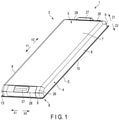
- FIG. 1 shows an example of a single battery 1 used in the battery module according to the first embodiment.
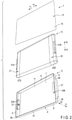
- FIG. 2 shows the battery 1 of FIG. 1 disassembled for each member.
- Each of the plurality of batteries provided in the battery module of the present embodiment has the same configuration as that of the battery 1 to be described below.
- the battery 1 is, for example, a secondary battery.
- the battery 1 includes a container 3.
- the container 3 is made of a metal such as stainless steel. Examples of a metal forming the container 3, other than stainless steel, include aluminum, an aluminum alloy, iron, and plated steel.
- An inner cavity 11 is formed inside the container 3.
- a depth direction (a direction indicated by arrows X1 and X2)
- a lateral direction (a direction indicated by arrows Y1 and Y2) intersecting (perpendicular or approximately perpendicular to) the depth direction
- a height direction (a direction indicated by arrows Z1 and Z2) intersecting (perpendicular or approximately perpendicular to) both the depth direction and the lateral direction, are defined.
- the container 3 includes a first container member (cup member) 5 and a second container member (lid member) 6.
- the first container member 5 is formed in a container shape with a bottom.
- the first container member 5 has a bottom wall 7 and a peripheral wall 4, and is formed in an approximately rectangular parallelepiped shape with one surface opened.
- the bottom wall 7 is located on one side (arrow Z1 side) in the height direction with respect to the inner cavity 11.
- the peripheral wall 4 extends along a circumferential direction of the container 3, and an outer peripheral side of the inner cavity 11 is surrounded by the peripheral wall 4.
- the inner cavity 11 is adjacent to an inner peripheral side relative to the peripheral wall 4.
- An internal space of the first container member 5 forms at least a part of the inner cavity 11 of the container 3, and opens toward a side opposite to a side where the bottom wall 7 is located.
- An opening edge of an opening of the internal space of the first container member 5 is formed at an end portion of the peripheral wall 4 on a side opposite to the bottom wall 7.
- a direction along the opening edge of the internal space of the first container member 5 coincides or approximately coincides with the circumferential direction.
- a side where the inner cavity 11 (internal space) is located with respect to the peripheral wall 4 is the inner peripheral side, and a side opposite to the inner peripheral side is an outer peripheral side.
- the peripheral wall 4 includes two pairs of side walls 8 and 9.
- the pair of side walls 8 face each other across the inner cavity 11 in the depth direction.
- the pair of side walls 9 face each other across the inner cavity 11 in the lateral direction.
- Each of the side walls 8 extends continuously along the lateral direction between the side walls 9.
- Each of the side walls 9 extends continuously along the depth direction between the side walls 8.
- the first container member 5 includes a flange 13.
- the flange 13 protrudes from the end portion of the peripheral wall 4 (side walls 8 and 9) on the side opposite to the bottom wall 7 toward the outer peripheral side.
- the flange 13 protrudes to the outer peripheral side with respect to the peripheral wall 4 and is formed away from the bottom wall 7 in the height direction.
- the flange 13 is formed over the entire circumference in the circumferential direction of the container 3, and protrudes to the outer peripheral side over the entire circumference in the circumferential direction of the container 3.
- the flange 13 extends from the opening edge of the internal space of the first container member 5 toward the outer peripheral side.
- the second container member 6 is an approximately plate-shaped member, and is formed in an approximately rectangular shape, for example.
- the second container member 6 is attached to the flange 13 from the side opposite to the side where the bottom wall 7 is located in the height direction of the battery 1, and faces the flange 13 from the side opposite to the bottom wall 7.
- the opening of the internal space of the first container member 5 is closed by the second container member 6.
- the second container member 6 includes a top wall 15 facing the bottom wall 7 across the inner cavity 11 in the height direction.
- the bottom wall 7 of the first container member 5 faces the second container member 6 (top wall 15) across the inner cavity 11 in the height direction.
- the peripheral wall 4 and the flange 13 are provided between the bottom wall 7 and the second container member 6 in the height direction.
- the second container member 6 protrudes to the outer peripheral side with respect to the peripheral wall 4 (side walls 8 and 9).
- the second container member 6 protrudes to the outer peripheral side over the entire circumference in the circumferential direction of the container 3.
- a thickness direction of the plate-like second container member 6 coincides or approximately coincides with the height direction of the battery 1 (container 3).
- the second container member 6 is welded to the flange 13 in a state of being arranged on a side opposite to the bottom wall 7 with respect to the flange 13.
- the flange 13 and the second container member 6 are airtightly welded.
- the welding portion of the flange 13 to the second container member 6 is formed on the outer peripheral side of the container 3 with respect to the opening edge of the internal space of the first container member 5.
- the welding portion between the flange 13 and the second container member 6 is formed continuously over the entire circumference in the circumferential direction.
- the inner cavity of the container 3 is sealed and closed off.
- the flange 13 and the second container member 6 are welded by, for example, resistance seam welding. Resistance seam welding allows for costs to be suppressed, and obtaining of a high degree of airtightness between the flange 13 and the second container member 6 as compared with laser welding, etc.
- a dimension in the height direction between the bottom wall 7 and the second container member 6 is much smaller than a dimension in the depth direction between the pair of side walls 8 and a dimension in the lateral direction between the pair of side walls 9.
- a dimension in the height direction is much smaller than each of a dimension in the depth direction and a dimension in the lateral direction.
- a wall thickness of the container 3 is uniform or approximately uniform over the entire container 3 (container members 5 and 6).
- the wall thickness of the container 3 is thin and is formed to be, for example, from 0.02 mm to 0.3 mm. Therefore, in the battery 1, a dimension in the height direction is much smaller than each of a dimension in the depth direction and a dimension in the lateral direction.
- the container 3 is formed in a flat shape in which a dimension in the height direction is smaller than each of a dimension in the depth direction and a dimension in the lateral direction. Further a protruding dimension of the flange 13 and the second container member 6 from the peripheral wall 4 to the outer peripheral side is about 2 mm to 5 mm.
- an outer peripheral end E of the container 3 (battery 1) is formed by a protruding end of each of the flange 13 and a protruding portion of the second container member 6.
- FIG. 3 is a diagram for explaining a configuration of the electrode group 10.
- the electrode group 10 is formed in a flat shape, for example, and includes a positive electrode 21, a negative electrode 22, and separators 23 and 25.
- the positive electrode 21 includes a positive electrode current collecting foil 21A serving as a positive electrode current collector, and a positive electrode active material-containing layer 21B supported on a surface of the positive electrode current collecting foil 21A.
- the positive electrode current collecting foil 21A is an aluminum foil or an aluminum alloy foil, etc., and has a thickness of about 10 ⁇ m to 20 ⁇ m.
- a slurry containing a positive electrode active material, a binder, and an electroconductive agent is applied to the positive electrode current collecting foil 21A.
- the positive electrode active material include, but are not limited to, oxides, sulfides, and polymers capable of occluding and releasing lithium.
- the positive electrode active material it is preferable to use a lithium-manganese composite oxide, a lithium-nickel composite oxide, a lithium-cobalt composite oxide, lithium iron phosphate, etc., since a high positive electrode electric potential can be obtained.
- the negative electrode 22 includes a negative electrode current collecting foil 22A serving as a negative electrode current collector, and a negative electrode active material-containing layer 22B supported on a surface of the negative electrode current collecting foil 22A.
- the negative electrode current collecting foil 22A is an aluminum foil, an aluminum alloy foil, or a copper foil, etc., and has a thickness of about 10 ⁇ m to 20 ⁇ m.
- a slurry containing a negative electrode active material, a binder, and a conductive agent is applied to the negative electrode current collecting foil 22A.
- the negative electrode active material include, but are not particularly limited to, a metal oxide, a metal sulfide, a metal nitride, and a carbon material, which can occlude and release lithium ions.
- the negative electrode active material is preferably a substance which occludes and releases lithium ions at an electric potential of 0.4 V or more with respect to a metal lithium electric potential, i.e., a substance which occludes and releases lithium ions at an electric potential of 0.4 V (vs. Li + /Li) or more.
- the reaction of aluminum or an aluminum alloy with lithium is suppressed by using the negative electrode active material having a lithium ion occlusion-and-release electric potential as described above, which allows for usage of aluminum and an aluminum alloy for the negative electrode current collecting foil 22A and a structural member related to the negative electrode 22.
- Examples of a negative electrode active material having a lithium ion occlusion-and-release electric potential of 0.4 V (vs.
- Li + /Li) or more are a titanium oxide, a lithium titanium composite oxide such as a lithium titanate, a tungsten oxide, an amorphous tin oxide, a niobium titanium composite oxide, a tin silicon oxide, and a silicon oxide, and it is particularly preferable to use a lithium titanium composite oxide as the negative electrode active material.
- a lithium titanium composite oxide such as a lithium titanate, a tungsten oxide, an amorphous tin oxide, a niobium titanium composite oxide, a tin silicon oxide, and a silicon oxide
- a lithium titanium composite oxide as the negative electrode active material.
- a copper foil may be used as the negative electrode current collecting foil 22A.
- the carbon material used as the negative electrode active material has a lithium ion occlusion-and-release electric potential of about 0 V (vs. Li + /Li).
- the aluminum alloy used for the positive electrode current collecting foil 21A and the negative electrode current collecting foil 22A preferably includes one or more kinds of elements selected from Mg, Ti, Zn, Mn, Fe, Cu, and Si.
- the purity of the aluminum and the aluminum alloy may be set to 98% by weight or more, and is preferably 99.99% by weight or more. Pure aluminum having a purity of 100% can be used as a material for the positive electrode current collector and/or the negative electrode current collector. It is preferable to set the contained amount of transition metal such as nickel and chrome in the aluminum and the aluminum alloy to 100 ppm by weight or less (including 0 ppm by weight).
- a positive electrode current collecting tab 21D is formed of one long side edge 21C and its nearby portion. In the example of FIG. 3 , the positive electrode current collecting tab 21D is formed over the entire length of the long side edge 21C. In the positive electrode current collecting tab 21D, the positive electrode active material-containing layer 21B is not supported on the surface of the positive electrode current collecting foil 21A. Therefore, the positive electrode current collecting foil 21A includes the positive electrode current collecting tab 21D as a portion on which the positive electrode active material-containing layer 21B is not supported. In addition, in the negative electrode current collecting foil 22A, a negative electrode current collecting tab 22D is formed of one long side edge 22C and its nearby portion. In the example of FIG.
- the negative electrode current collecting tab 22D is formed over the entire length of the long side edge 22C.
- the negative electrode active material-containing layer 22B is not supported on the surface of the negative electrode current collecting foil 22A. Therefore, the negative electrode current collecting foil 22A includes the negative electrode current collecting tab 22D as a portion on which the negative electrode active material-containing layer 22B is not supported.
- Each of the separators 23 and 25 is made of an electrically insulating material, and electrically insulates between the positive electrode 21 and the negative electrode 22.
- Each of the separators 23 and 25 may be a separate sheet from the positive electrode 21 and the negative electrode 22, etc., or may be formed integrally with one of the positive electrode 21 and the negative electrode 22.
- the separators 23 and 25 may be made of an organic material, an inorganic material, or a mixture of an organic material and an inorganic material. Examples of organic materials forming the separators 23 and 25 include engineering plastics and super engineering plastics.
- Examples of engineering plastics include polyamide, polyacetal, polybutylene terephthalate, polyethylene terephthalate, syndiotactic polystyrene, polycarbonate, polyamideimide, polyvinyl alcohol, polyvinylidene fluoride, modified polyphenylene ether, etc.
- Examples of super engineering plastics include polyphenylene sulfide, polyether ether ketone, liquid crystal polymer, polyvinylidene fluoride, polytetrafluoroethylene (PTFE), polyether nitrile, polysulfone, polyacrylate, polyetherimide, thermoplastic polyimide, etc.
- Examples of inorganic materials forming the separators 23 and 25 include oxides (e.g., aluminum oxide, silicon dioxide, magnesium oxide, phosphorus oxide, calcium oxide, iron oxide, titanium oxide), nitrides (e.g., boron nitride, aluminum nitride, silicon nitride, barium nitride), etc.
- oxides e.g., aluminum oxide, silicon dioxide, magnesium oxide, phosphorus oxide, calcium oxide, iron oxide, titanium oxide
- nitrides e.g., boron nitride, aluminum nitride, silicon nitride, barium nitride
- the positive electrode 21, the negative electrode 22, and the separators 23 and 25 are wound around a winding axis B into a flat shape, with the separators 23 and 25 being interposed between the positive electrode active material-containing layer 21B and the negative electrode active material-containing layer 22B, respectively.
- the positive electrode 21, the separator 23, the negative electrode 22, and the separator 25 are wound in a state of being stacked in this order, for example.
- the positive electrode current collecting tab 21D of the positive electrode current collecting foil 21A protrudes to one side in a direction along the winding axis B with respect to the negative electrode 22 and the separators 23 and 25.
- the negative electrode current collecting tab 22D of the negative electrode current collecting foil 22A protrudes to a side opposite to a side where the positive electrode current collecting tab 21D protrudes in the direction along the winding axis B with respect to the positive electrode 21 and the separators 23 and 25.
- the electrode group 10 is arranged in a state in which the winding axis B is parallel or approximately parallel to the lateral direction of the battery 1.
- the positive electrode current collecting tab 21D protrudes to one side in the lateral direction with respect to the negative electrode 22 and the separators 23 and 25.
- the negative electrode current collecting tab 22D protrudes to a side opposite to a side where the positive electrode current collecting tab 21D protrudes in the lateral direction with respect to the positive electrode 21 and the separators 23 and 25.
- the electrode group 10 does not need to have a wound structure in which the positive electrode, negative electrode, and separators are wound.
- the electrode group 10 has a stack structure in which a plurality of positive electrodes and a plurality of negative electrodes are alternately stacked, and a separator is provided between the positive electrode and the negative electrode.
- the positive electrode current collecting tab protrudes to one side in the lateral direction of the battery 1 (container 3) with respect to the negative electrode.
- the negative electrode current collecting tab protrudes toward a side opposite to a side where the positive electrode current collecting tab protrudes in the lateral direction of the battery 1 with respect to the positive electrode.
- an electrolytic solution (not shown) is impregnated into the electrode group 10 in the inner cavity 11.
- a nonaqueous electrolytic solution is used; for example, a nonaqueous electrolytic solution prepared by dissolving an electrolyte into an organic solvent is used.
- lithium salts such as lithium perchlorate (LiClO 4 ), lithium hexafluorophosphate (LiPF 6 ), lithium tetrafluoroborate (LiBF 4 ), lithium hexafluoride arsenate (LiAsF 6 ), lithium trifluoromethanesulfonate (LiCF 3 SO 3 ), and lithium bistrifluoromethylsulfonylimide [LiN(CF 3 SO 2 ) 2 ], and any mixtures thereof may be used.
- lithium perchlorate LiClO 4
- LiPF 6 lithium hexafluorophosphate
- LiBF 4 lithium tetrafluoroborate
- LiAsF 6 lithium hexafluoride arsenate
- LiCF 3 SO 3 lithium trifluoromethanesulfonate
- LiBN(CF 3 SO 2 ) 2 lithium bistrifluoromethylsulfonylimide
- organic solvent examples include: cyclic carbonate, such as propylene carbonate (PC), ethylene carbonate (EC), or vinylene carbonate; chain carbonate, such as diethyl carbonate (DEC), dimethyl carbonate (DMC), or methyl ethyl carbonate (MEC); cyclic ether, such as tetrahydrofuran (THF), 2-methyltetrahydrofuran (2MeTHF), and dioxolane (DOX); chain ether, such as dimethoxyethane (DME) and diethoxyethane (DEE); ⁇ -butyrolactone (GBL), acetonitryl (AN), and sulfolane (SL). These organic solvents may be used either individually or as a mixed solvent.
- cyclic carbonate such as propylene carbonate (PC), ethylene carbonate (EC), or vinylene carbonate
- chain carbonate such as diethyl carbonate (DEC), dimethyl carbonate (DMC), or methyl eth
- a gel nonaqueous electrolyte which is a composite of a nonaqueous electrolytic solution and a polymeric material is used as a nonaqueous electrolyte instead of an electrolytic solution.
- the above-described electrolyte and organic solvent are used.
- the polymeric material include polyvinylidene fluoride (PVdF), polyacrylonitrile (PAN), and polyethylene oxide (PEO).
- a solid electrolyte such as a polymeric solid electrolyte and an inorganic solid electrolyte, is provided as a nonaqueous electrolyte instead of an electrolytic solution.
- the separators 23 and 25 may not be provided in the electrode group 10.
- the solid electrolyte is sandwiched between the positive electrode 21 and the negative electrode 22.
- the positive electrode 21 and the negative electrode 22 are electrically insulated from each other by the solid electrolyte.
- an aqueous electrolyte containing an aqueous solvent may be used as an electrolyte instead of a nonaqueous electrolyte.
- a pair of electrode terminals 27 are attached to an outer surface of the container 3.
- One of the electrode terminals 27 serves as a positive electrode terminal of the battery 1, and the other of the electrode terminals 27 serves as a negative electrode terminal of the battery 1.
- the electrode terminals 27 have electrical polarities opposite to each other.
- a pair of inclined surfaces 26 are formed on an outer surface of the first container member 5.
- Each of the inclined surfaces 26 is provided between a corresponding one of the side walls (first side walls) 9 and the bottom wall 7.
- Each of the pair of inclined surfaces 26 extends continuously along the depth direction between the side walls 8.
- each of the inclined surfaces 26 extends over the same or approximately the same range as that of the corresponding one of the side walls 9 in the circumferential direction of the battery 1 (container 3).
- Each of the inclined surfaces 26 is inclined with respect to the bottom wall 7 and the side wall 9.
- Each of the inclined surfaces 26 is inclined in a state that the inclined surface extends toward an inner side in the lateral direction as it approaches toward the bottom wall 7.
- each of the electrode terminals 27 is attached to a corresponding one of the inclined surfaces 26 in a state of being exposed to the outside. Therefore, each of the electrode terminals 27 is provided in a range in which a corresponding one of the side walls (first side walls) 9 extends in the circumferential direction of the container 3.
- each of the electrode terminals 27 is arranged at a central position or an approximately central position of a corresponding one of the inclined surfaces 26 in the depth direction.
- the electrode group 10 is arranged between the pair of electrode terminals 27 in the lateral direction.
- Each of the electrode terminals 27 is made of a conductive material, and, for example, is made of any one of aluminum, copper, stainless steel, etc.
- a pair of insulating members 28 made of an electrically insulating material are provided on the outer surface of the first container member 5.
- Each of the insulating members 28 is arranged on an outer surface of a corresponding one of the side walls 9 and a corresponding one of the inclined surfaces 26.
- Each of the insulating members 28 is interposed between a corresponding one of the inclined surfaces 26 and a corresponding one of the electrode terminals 27, and electrically insulates the corresponding one of the electrode terminals 27 from the container 3 (first container member 5).
- FIG. 4 shows an electrical connection configuration between the electrode group 10 and one of the pair of electrode terminals 27.
- the positive electrode current collecting tab 21D of the electrode group 10 is bundled by welding such as ultrasonic welding.
- the bundle of the positive electrode current collecting tab 21D is electrically connected to a corresponding one (positive electrode terminal) of the electrode terminals 27 via one or more positive electrode leads including a positive electrode backup lead 31A, a positive electrode relay lead 32A, a positive electrode terminal lead 33A, etc.
- Connections between the positive electrode current collecting tab 21D and the positive electrode lead, between the positive electrode leads, and between the positive electrode lead and the positive electrode terminal are performed by welding such as ultrasonic welding.
- the positive electrode lead is made of a conductive metal.
- the positive electrode terminal (corresponding one of 27), the positive electrode current collecting tab 21D, and the positive electrode lead are electrically insulated from the container 3 (container members 5 and 6) by an insulating member (not shown), etc.
- the negative electrode current collecting tab 22D of the electrode group 10 is bundled by welding such as ultrasonic welding.
- the bundle of the negative electrode current collecting tab 22D is electrically connected to a corresponding one (negative electrode terminal) of the electrode terminals 27 via one or more negative electrode leads including a negative electrode backup lead 31B, a negative electrode relay lead 32B, a negative electrode terminal lead 33B, etc. Connections between the negative electrode current collecting tab 22D and the negative electrode lead, between the negative electrode leads, and between the negative electrode lead and the negative electrode terminal are performed by welding such as ultrasonic welding.
- the negative electrode lead is made of a conductive metal.
- the negative electrode terminal (corresponding one of 27), the negative electrode current collecting tab 22D, and the negative electrode lead are electrically insulated from the container 3 (container members 5 and 6) by an insulating member (not shown), etc.
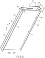
- FIGS. 5 and 6 show an example of a battery assembly 40.
- a depth direction (the direction indicated by arrows X1 and X2)
- a lateral direction (the direction indicated by arrows Y1 and Y2) intersecting (perpendicular or approximately perpendicular to) the depth direction
- a height direction (the direction indicated by arrows Z1 and Z2) intersecting (perpendicular or approximately perpendicular to) both the depth direction and the lateral direction
- a dimension in the height direction is much smaller than each of a dimension in the depth direction and a dimension in the lateral direction.
- FIG. 6 shows the battery assembly 40 when viewed from one side in the lateral direction.
- a cover member 41 is formed in an approximately plate-like shape and includes a base 42 and a pair of side plate parts 43.
- the base 42 faces the bottom wall 7 of the first container member 5 of the battery 1 and abuts on an outer surface of the bottom wall 7.
- the base 42 extends parallel or approximately parallel to the bottom wall 7, and extends parallel or approximately parallel to the depth direction and the lateral direction of the battery assembly 40.
- a thickness direction of the cover member 41 coincides or approximately coincides with the height direction of the battery assembly 40.
- the base 42 is in surface contact with the entire or approximately the entire outer surface of the bottom wall 7. However, the base 42 is not in contact with each of the electrode terminals 27.
- the base 42 protrudes to the outer peripheral side (outer side) with respect to the peripheral wall 4 (side walls 8 and 9).
- the base 42 protrudes to an outer side in the lateral direction with respect to the electrode terminals 27.
- Each of the side plate parts 43 extends from a protruding end of the base 42 with respect to a corresponding one of the pair of side walls 8 or the vicinity thereof to a side where the flange 13 (second container member 6) is located.
- Each of the side plate parts 43 extends parallel or approximately parallel to the side wall (second side wall) 8, and extends parallel or approximately parallel to the lateral direction and the height direction of the battery assembly.
- the thickness direction of the cover member 41 coincides or approximately coincides with the depth direction of the battery assembly 40.
- Each of the side plate parts 43 is provided over the entire or approximately the entire range in which a corresponding one of the side walls 8 extends in the circumferential direction of the battery 1. Therefore, in the present embodiment, the side plate part 43 is not provided in ranges in which the side walls (first side walls) 9 extend and ranges in which the electrode terminals 27 are located in the circumferential direction of the battery 1.
- Each of the side plate parts 43 faces a corresponding one of the side walls 8 from an outer side in the depth direction.
- Each of the side plate parts 43 faces an outer surface of a corresponding one of the side walls 8 with a gap between the side plate part 43 and the corresponding one of the side walls 8.
- the side plate part 43 faces the peripheral wall 4 from the outer peripheral side in ranges away from both of the pair of electrode terminals 27 in the circumferential direction of the battery 1.
- a gap is formed between each of the side walls (second side walls) 8 and a corresponding one of the side plate parts 43 along the lateral direction of the battery assembly 40.
- each of the side plate parts 43 extends toward a side opposite to a side where the base 42 is located, beyond the flange 13 and the second container member 6. In addition, in the present embodiment, each of the side plate parts 43 extends through an outer side with respect to the protruding end (the outer peripheral end E of the container 3) of each of the flange 13 and the second container member 6. Each of the side plate parts 43 protrudes from the second container member 6 to the side opposite to the side where the bottom wall 7 is located in the height direction.
- the cover member 41 may be entirely formed of an insulating layer made of an insulating resin, etc., or may have a structure in which an insulating layer and a metal layer are stacked. However, in the base 42 and the side plate parts 43, it is preferable that the entire or approximately the entire surface facing a side opposite to a side where the first container member 5 is located is formed of an insulating layer. Examples of the resin forming the insulating layer include polyethylene and polypropylene. Further, for example, when the cover member 41 is formed of an insulating layer and a metal layer, in the cover member 41, a layer thickness of the insulating layer is about 0.05 mm to 0.3 mm. A thickness of the cover member 41 is about 0.6 mm to 1.2 mm, and is minute.
- Each of the side plate parts 43 includes extension parts 45 and 46 and a level difference 47 formed between the extension parts 45 and 46.
- the extension part (second cover extension part) 46 is arranged on the side opposite to the side where the base 42 is located with respect to the extension part (first cover extension part) 45.
- the extension part 45 is continuous with the base 42, and the extension part 46 protrudes from the second container member 6 to the side opposite to the side where the bottom wall 7 is located.
- the extension part 46 is arranged on the outer side in the depth direction with respect to the extension part 45 due to the level difference 47. That is, the level difference 47 is formed between the extension parts 45 and 46 in a state in which the extension part 46 is located on the outer side (outer peripheral side) with respect to the extension part 45.
- FIGS. 7 and 8 show an example of a battery module 50.
- a plurality of battery assemblies 40 are stacked (arrayed) in a stacking direction (the direction indicated by arrows Z3 and Z4).
- a plurality of batteries 1 are stacked in the stacking direction (array direction).
- a first intersecting direction (the direction indicated by arrows Y3 and Y4) intersecting (perpendicular or approximately perpendicular to) the stacking direction
- a second intersecting direction (the direction indicated by arrows X3 and X4) intersecting (perpendicular or approximately perpendicular to) both the stacking direction and the first intersecting direction
- a virtual central axis of the battery module 50 along the stacking direction is defined.
- a side away from the virtual central axis is defined as an outer side (outer peripheral side)
- a side approaching the virtual central axis is defined as an inner side (inner peripheral side).
- each of the plurality of battery assemblies 40 is arranged in a state in which the height direction thereof coincides or approximately coincides with the stacking direction (array direction).
- Each of the battery assemblies 40 is arranged in a state in which the lateral direction coincides or approximately coincides with the first intersecting direction and the depth direction coincides or approximately coincides with the second intersecting direction. Therefore, in the battery module 50, each of the plurality of batteries 1 is arranged in a state in which the height direction thereof is along the stacking direction.
- Each of the batteries 1 is arranged in a state in which the lateral direction is along the first intersecting direction and the depth direction is along the second intersecting direction.
- a cavity in which a stacked body of the battery assemblies 40 is accommodated is defined by a frame including substrates 51 and 52, etc. That is, in the battery module 50, the stacked body of the battery assemblies 40 is arranged in the cavity surrounded by the frame including the substrates 51 and 52, etc.
- the substrate 51 faces the stacked body of the battery assemblies 40 from one side (arrow Z4 side) in the stacking direction.
- the substrate 52 faces the stacked body of the battery assemblies 40 from one side (arrow Y4 side) in the first intersecting direction.
- FIG. 7 shows only the substrates 51 and 52 in the frame surrounding the stacked body of the battery assemblies 40. In FIG. 8 , the frame is omitted.
- a substrate similar to the substrate 51 faces the stacked body of the battery assemblies 40 from a side (arrow Z3 side) opposite to the substrate 51 in the stacking direction.
- a substrate similar to the substrate 52 faces the stacked body of the battery assemblies 40 from a side (arrow Y3 side) opposite to the substrate 51 in the first intersecting direction.
- the battery module 50 is provided with a plurality of bus bars 55 and the same number of engagement members 56 as that of bus bars 55.
- Each of the bus bars 55 is made of a conductive metal.
- Each of the bus bars 55 electrically connects two corresponding batteries 1 adjacent to each other in the stacking direction among the batteries 1.
- Each of the engagement members 56 is made of, for example, an electrically insulating resin, etc.
- the battery assembly (first battery assembly) 40 ⁇ is any one of the battery assemblies 40
- the battery assembly (second battery assembly) 40 ⁇ is one of the battery assemblies 40 that is adjacent to the battery assembly 40 ⁇ on the arrow Z3 side.
- the battery 1 is referred to as a battery (first battery) 1 ⁇
- the cover member 41 is referred to as a cover member (first cover member) 41 ⁇ .
- the battery 1 is referred to as a battery (second battery) 1 ⁇
- the cover member 41 is referred to as a cover member (second cover member) 41 ⁇
- the pair of electrode terminals 27 are referred to as electrode terminals (first electrode terminals) 27 ⁇
- the pair of electrode terminals 27 are referred to as electrode terminals (second electrode terminals) 27 ⁇ .
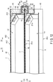
- FIGS. 9 and 10 show a configuration of one of the bus bars 55 and the vicinity thereof.
- FIGS. 11 and 12 show configurations of the two battery assemblies 40 ⁇ and 40 ⁇ arranged adjacent to each other and the vicinity thereof.
- FIGS. 10 and 12 show cross sections perpendicular or approximately perpendicular to the second intersecting direction of the battery module 50, that is, cross sections perpendicular or approximately perpendicular to the depth direction of the battery assemblies 40 ⁇ and 40 ⁇ .
- the bottom wall 7 of the battery (first battery) 1 ⁇ faces the second container member 6 of the battery (second battery) 1 ⁇ with the base 42 of the cover member 41 ⁇ interposed therebetween.
- the cover member 41 ⁇ of the battery assembly 40 ⁇ prevents the bottom wall 7 of the battery 1 ⁇ from contacting the second container member 6 of the battery 1 ⁇ .
- a partition wall that partitions between the batteries 1 ⁇ and 1 ⁇ in the stacking direction is formed by the base 42 of the cover member (first cover member) 41 ⁇ .
- the base 42 of the cover member 41 ⁇ protrudes to the outer side (outer peripheral side) with respect to the electrode terminal 27 ⁇ of the battery 1 ⁇ and the electrode terminal 27 ⁇ of the battery 1 ⁇ in the first intersecting direction.
- the batteries 1 ⁇ and 1 ⁇ stacked adjacent to each other are electrically connected by one of the bus bars 55 in the following manner.
- a first target terminal which is a corresponding one of the pair of electrode terminals 27 ⁇ of the battery (first battery) 1 ⁇ is electrically connected to a second target terminal which is a corresponding one of the electrode terminals 27 ⁇ of the battery (second battery) 1 ⁇ via the bus bar 55.
- the first target terminal (corresponding one of 27 ⁇ ) of the battery 1 ⁇ and the second target terminal (corresponding one of 27 ⁇ ) of the battery 1 ⁇ , which are electrically connected by the bus bar 55 are located on the same side with respect to a central position of the battery module 50 in the first intersecting direction. That is, the first target terminal (corresponding one of 27 ⁇ ), the second target terminal (corresponding one of 27 ⁇ ), and the bus bar 55 are located on the same side with respect to the electrode groups 10 of the batteries 1 ⁇ and 1 ⁇ in the first intersecting direction.
- the batteries 1 ⁇ and 1 ⁇ are electrically connected in series. Therefore, one of the first target terminal and the second target terminal connected by the bus bar 55 is a positive electrode terminal, and the other one is a negative electrode terminal.
- the batteries 1 ⁇ and 1 ⁇ may be electrically connected in parallel by using two bus bars 55.
- the positive electrode terminals of the batteries 1 ⁇ and 1 ⁇ are connected to each other by one of the bus bars 55 on one side with respect to the central position of the battery module 50 in the first intersecting direction.
- the negative electrode terminals of the batteries 1 ⁇ and 1 ⁇ are connected to each other by the other one of the bus bars 55.
- each of the bus bars 55 includes a first connector 61 and a second connector 62.
- the first connector 61 is provided with a first contact part 63 which contacts the first target terminal (corresponding one of 27 ⁇ ) of the battery (first battery) 1 ⁇ .
- the second connector 62 is provided with a second contact part 65 which contacts the second target terminal (corresponding one of 27 ⁇ ) of the battery (second battery) 1 ⁇ .
- the first contact part 63 contacts the first target terminal (corresponding one of 27 ⁇ ) from the outer side in the first intersecting direction (the lateral direction of the battery 1 ⁇ ), and is connected to the first target terminal (corresponding one of 27 ⁇ ) by welding, etc.
- the second contact part 65 contacts the second target terminal (corresponding one of 27 ⁇ ) from the outer side in the first intersecting direction (the lateral direction of the battery 1 ⁇ ), and is connected to the second target terminal (corresponding one of 27 ⁇ ) by welding, etc.
- Each of the bus bars 55 includes a pair of bar relay parts 66 that relay between the first connector 61 (first contact part 63) and the second connector 62 (second contact part 65).
- each of the bar relay parts 66 relays between the connectors 61 and 62 beyond the base 42 of the cover member 41 ⁇ . That is, each of the bar relay parts 66 extends along the stacking direction between the connectors 61 and 62 beyond the partition wall between the batteries 1 ⁇ and 1 ⁇ .
- the pair of bar relay parts 66 are arranged apart from each other in the second intersecting direction (the depth direction of the batteries 1 ⁇ and 1 ⁇ ). With the above-described configuration, the bus bar 55 connecting the batteries 1 ⁇ and 1 ⁇ adjacent to each other has an approximately O shape when viewed from the outer side in the first intersecting direction.
- each of the bar relay parts 66 includes relay portions 71 to 73.
- the relay portion (first relay portion) 71 extends from the first connector 61 to the outer side in the first intersecting direction.
- the relay portion (second relay portion) 72 extends from the second connector 62 to the outer side in the first intersecting direction.
- the relay portion (third relay portion) 73 is continuous between the relay portions 71 and 72 along the stacking direction.
- each of the bar relay parts 66 is arranged on the outer side (outer peripheral side) with respect to the protruding end of the base (partition wall) 42 in the first intersecting direction.
- Each of the bar relay parts 66 has an approximately U shape when viewed from the second intersecting direction.
- a through hole C1 is formed in the first connector 61 and a through hole C2 is formed in the second connector 62.
- each of the through holes C1 and C2 is formed in an elongated hole shape along the second intersecting direction (the depth direction of the batteries 1 ⁇ and 1 ⁇ ).
- the first connector 61 an edge of the through hole C1 and the vicinity thereof serve as the first contact part 63 which comes into contact with the first target terminal (corresponding one of 27 ⁇ ).
- an edge of the through hole C2 and the vicinity thereof serve as the second contact part 65 which comes into contact with the second target terminal (corresponding one of 27 ⁇ ) .
- the first connector 61 includes an extension portion 77 extending from the first contact part 63 to a side where the battery 1 ⁇ (second connector 62) is located in the stacking direction.
- the extension portion 77 is located between the bar relay parts 66 in the second intersecting direction.
- the second connector 62 includes an extension portion 78 extending from the second contact part 65 to a side opposite to a side where the battery 1 ⁇ (first connector 61) is located in the stacking direction.
- the bus bar 55 connecting the batteries 1 ⁇ and 1 ⁇ is coupled to the base 42 of the cover member 41 ⁇ via a corresponding one of the engagement members 56. That is, the bus bar 55 is coupled to the partition wall between the batteries 1 ⁇ and 1 ⁇ . In the base 42, the bus bar 55 is coupled to a portion protruding to the outer side in the first intersecting direction with respect to the first target terminal (corresponding one of 27 ⁇ ) and the second target terminal (corresponding one of 27 ⁇ ).
- a corresponding one of the engagement members 56 is engaged with a protruding portion of the base (partition wall) 42 of the cover member 41 ⁇ with respect to the first target terminal (corresponding one of 27 ⁇ ) and the second target terminal (corresponding one of 27 ⁇ ).
- the corresponding one of the engagement members 56 is attached to the base 42 from the outer side in the first intersecting direction.
- Each of the engagement members 56 includes a pair of projections 67. In the engagement member 56 which engages with the base 42 of the cover member 41 ⁇ , the projections 67 are arranged apart from each other in the second intersecting direction (the depth direction of the batteries 1 ⁇ and 1 ⁇ ).
- each of the bar relay parts 66 is engaged with a corresponding one of the pair of projections 67 of a corresponding one of the engagement members 56.
- the bus bar 55 is attached to the corresponding one of the engagement members 56 at the bar relay part 66.
- the bus bar 55 is coupled to the base (partition wall) 42 of the cover member 41 ⁇ via a corresponding one of the engagement members 56 at the bar relay part 66. Therefore, the bus bar 55 is coupled at a portion between the first contact part 63 and the second contact part 65 to the protruding portion of the partition wall between the batteries 1 ⁇ and 1 ⁇ with respect to the first target terminal (corresponding one of 27 ⁇ ) and the second target terminal (corresponding one of 27 ⁇ ) .
- each of the engagement members 56 is provided with a pair of insertion pieces 57.
- the pair of insertion pieces 57 are arranged apart from each other in the second intersecting direction.
- a plurality of recessed portions 58 are formed in each of the substrate 52 and a substrate (not shown) facing the substrate 52 across the stacked body of the battery assemblies 40.
- the total number of insertion pieces 57 in all of the engagement members 56 is the same as the total number of recessed portions 58 in the frame formed of the substrate 52, etc. In the example of FIG. 7 , etc., the total number of insertion pieces 57 in all of the engagement members 56 is twice the number of engagement members 56 and twice the number of bus bars 55.
- Each of the recessed portions 58 is recessed toward the inner side in the first intersecting direction.
- Each of the insertion pieces 57 is inserted into a corresponding one of the recessed portions 58 from the inner side in the second intersecting direction.
- a dimension of each of the insertion pieces 57 in the stacking direction is smaller than a dimension of a corresponding one of the recessed portions 58 in the stacking direction.
- the extension part (second cover extension part) 46 of each of the side plate parts 43 of the cover member (second cover member) 41 ⁇ protrudes from the second container member 6 of the battery 1 ⁇ to a side where the battery 1 ⁇ is located.
- Each of the extension parts (second cover extension parts) 46 of the cover member (second cover member) 41 ⁇ abuts on the extension part (first cover extension part) 45 of a corresponding one of the side plate parts 43 of the cover member (first cover member) 41 ⁇ from the outer side (outer peripheral side) in the second intersecting direction. Thereby, movement of the battery assembly 40 ⁇ in the second intersecting direction (the depth direction of the batteries 1 ⁇ and 1 ⁇ ) relative to the battery assembly 40 ⁇ is restricted.
- a plurality of battery assemblies 40 are stacked in a cavity surrounded by a frame including the substrates 51 and 52, etc. to form a stacked body of the battery assemblies 40.
- a partition wall between the batteries 1 ⁇ and 1 ⁇ is formed by the base 42 of the cover member (first cover member) 41 ⁇ .
- Each of the bus bars 55 electrically connects two corresponding batteries 1 adjacent to each other in the stacking direction.
- the batteries 1 ⁇ and 1 ⁇ adjacent to each other are electrically connected by one of the bus bars 55.
- one of the bus bars 55 is attached to a corresponding one of the engagement members 56.
- the bus bar 55 is attached to the engagement member 56 by engaging each of the bar relay parts 66 with a corresponding one of the pair of projections 67.
- each of the pair of insertion pieces 57 of the engagement member 56 is inserted into a corresponding one of the recessed portions 58 of the frame.
- the engagement member 56 is attached to the base 42 of the cover member 41 ⁇ in a state in which each of the insertion pieces 57 is inserted into a corresponding one of the recessed portions 58.
- the engagement member 56 engages with the protruding portion of the base (partition wall) 42 of the cover member 41 ⁇ with respect to the first target terminal (corresponding one of 27 ⁇ ) and the second target terminal (corresponding one of 27 ⁇ ).
- the bus bar 55 is coupled to the base (partition wall) 42 of the cover member 41 ⁇ via the corresponding one of the engagement members 56 at the bar relay part 66.
- a dimension of each of the insertion pieces 57 in the stacking direction is smaller than a dimension of a corresponding one of the recessed portions 58 in the stacking direction.
- positions of the bus bar 55 and the engagement member 56 in the stacking direction can be adjusted to a position where they are easily coupled to the base 42 of the cover member 41 ⁇ . This improves workability in a work of engaging the engagement member 56 with the base 42 of the cover member 41 ⁇ , that is, a work of coupling the bus bar 55 to the partition wall between the batteries 1 ⁇ and 1 ⁇ .
- the first connector 61 of the bus bar 55 is brought into contact with the first target terminal (corresponding one of 27 ⁇ ) of the battery (first battery) 1 ⁇ to form the first contact part 63.
- the second connector 62 of the bus bar 55 is brought into contact with the second target terminal (corresponding one of 27 ⁇ ) of the battery (second battery) 1 ⁇ to form the second contact part 65.
- the first contact part 63 is welded to the first target terminal (corresponding one of 27 ⁇ )
- the second contact part 65 is welded to the second target terminal (corresponding one of 27 ⁇ ).
- the battery module 50 dimensions, etc. may vary among the batteries 1 (battery assemblies 40).
- positions of the two target terminals (the first target terminal and the second target terminal) connected by the bus bar 55 may be shifted from each other in a direction intersecting the stacking direction. That is, there is a possibility that the first target terminal (corresponding one of 27 ⁇ ) and the second target terminal (corresponding one of 27 ⁇ ) may be shifted from each other in the first intersecting direction, for example.
- the second target terminal (corresponding one of 27 ⁇ ) of the battery 1 ⁇ may be shifted from the first target terminal (corresponding one of 27 ⁇ ) of the battery 1 ⁇ to the inner side in the first intersecting direction.
- the second target terminal (corresponding one of 27 ⁇ ) of the battery 1 ⁇ may be shifted from the first target terminal (corresponding one of 27 ⁇ ) of the battery 1 ⁇ to the outer side in the first intersecting direction.
- the bus bar 55 and the engagement member 56 are swingable (rotatable) together about a swinging axis (rotational axis) P1 relative to the battery assemblies 40 ⁇ and 40 ⁇ .
- the swinging axis P1 passes through an engagement portion between the base 42 of the cover member 41 ⁇ and the engagement member 56, and extends along the second intersecting direction.
- the bus bar 55 can be easily adjusted to a state in which the first connector 61 is in contact with the first target terminal (corresponding one of 27 ⁇ ) and the second connector 62 is in contact with the second target terminal (corresponding one of 27 ⁇ ). That is, it is easy to form a state in which the first connector 61 contacts the first target terminal (corresponding one of 27 ⁇ ) and the second connector 62 contacts the second target terminal (corresponding one of 27 ⁇ ).
- the first connector 61 contacts the first target terminal (corresponding one of 27 ⁇ ) and the second connector 62 contacts the second target terminal (corresponding one of 27 ⁇ ) is easily formed, the first connector 61 is easily welded to the first target terminal (corresponding one of 27 ⁇ ) and the second connector 62 is easily welded to the second target terminal (corresponding one of 27 ⁇ ). Therefore, in the present embodiment, even when positions of the two target terminals connected by the bus bar 55 are shifted from each other in a direction (e.g., the first intersecting direction) intersecting the stacking direction, the work efficiency of a work of connecting the two target terminals by the bus bar 55 is ensured. That is, regardless of relative positions of the two target terminals connected by the bus bar 55, the work efficiency of the work of connecting the two target terminals by the bus bar 55 is ensured.
- the bus bar 55 is appropriately connected to the first target terminal (corresponding one of 27 ⁇ ). Since the second connector 62 is easily welded to the second target terminal (corresponding one of 27 ⁇ ), the bus bar 55 is appropriately connected to the second target terminal (corresponding one of 27 ⁇ ).
- the reliability of the battery module 50 is ensured. That is, the bus bar 55 is appropriately connected to the two target terminals regardless of the relative positions of the two target terminals connected by the bus bar 55, and the reliability of the battery module 50 is ensured.
- the extension part (second cover extension part) 46 of the cover member (second cover member) 41 ⁇ abuts on the extension part (first cover extension part) 45 of the side plate part 43 of the cover member (first cover member) 41 ⁇ from the outer side (outer peripheral side) in the second intersecting direction.
- movement of the battery assembly 40 ⁇ relative to the battery assembly 40 ⁇ in the second intersecting direction (the depth direction of the batteries 1 ⁇ and 1 ⁇ ) is restricted. Since the movement of the battery assembly 40 ⁇ relative to the battery assembly 40 ⁇ in the second intersecting direction is restricted, it is difficult to separate the battery assemblies 40 ⁇ and 40 ⁇ from each other in the battery module 50. This improves the strength of the battery module 50 against impact.
- the extension portions 77 and 78 are not provided in each of the bus bars 55.
- the extension portion 77 is cut after the first contact part 63 of the first connector 61 is welded to the first target terminal (corresponding one of 27 ⁇ ). Then, after the second contact part 65 of the second connector 62 is welded to the second target terminal (corresponding one of 27 ⁇ ), the extension portion 78 is cut.
- the bus bar 55 connecting the batteries 1 ⁇ and 1 ⁇ is provided with the first connector 61 and the second connector 62.
- the first contact part 63 of the first connector 61 that contacts the first target terminal (corresponding one of 27 ⁇ ) is formed in a linear shape along the second intersecting direction (the depth direction of the battery 1 ⁇ ).
- the second contact part 65 of the second connector 62 that contacts the second target terminal (corresponding one of 27 ⁇ ) is formed in a linear shape along the second intersecting direction (the depth direction of the battery 1 ⁇ ).
- the first connector 61 is provided with an extension part (first bar extension part) 81
- the second connector 62 is provided with an extension part (second bar extension part) 82.
- the extension part 81 extends from the first contact part 63 to a side opposite to a side where the battery (second battery) 1 ⁇ is located in the stacking direction.
- the extension part 82 extends from the second contact part 65 to a side where the battery (first battery) 1 ⁇ is located in the stacking direction.
- the bar relay part 66 relays between the extension parts 81 and 82.
- the extension part 81 is continuous with the bar relay part 66 at an end on a side where the first contact part 63 is located.
- the extension part 82 is continuous with the bar relay part 66 at an end on a side opposite to a side where the second contact part 65 is located. Also in this modification, the bar relay part 66 extends beyond the base (partition wall) 42 of the cover member 41 ⁇ between the connectors 61 and 62.
- the bus bar 55 is coupled to the partition wall between the batteries 1 ⁇ and 1 ⁇ at the bar relay part 66.
- the extension part (first bar extension part) 81 extends so as to be located on an outer side in a direction intersecting the stacking direction as it extends away from the battery (second battery) 1 ⁇ in the stacking direction. That is, the extension part 81 extends so as to be located on the outer side in the first intersecting direction as it is away from the bar relay part 66 in the stacking direction.
- the extension part (second bar extension part) 82 extends so as to be located on an outer side in the direction intersecting the stacking direction as it approaches toward the battery (first battery) 1 ⁇ in the stacking direction. That is, the extension part 82 extends so as to be located on the outer side in the first intersecting direction as it extends toward the bar relay part 66 in the stacking direction.
- the partition wall between the batteries 1 ⁇ and 1 ⁇ is formed by the base 42 of the cover member 41 ⁇ , but it is not limited thereto.
- a partition plate is provided between the batteries 1 ⁇ and 1 ⁇ , and the partition plate forms a partition wall between the batteries 1 ⁇ and 1 ⁇ .
- at least a part of the partition plate is made of an electrically insulating material.
- the partition wall prevents the containers 3 of the batteries 1 ⁇ and 1 ⁇ from coming into contact with each other, and effectively prevents the containers 3 of the batteries 1 ⁇ and 1 ⁇ from being electrically connected to each other.
- the partition wall between the batteries 1 ⁇ and 1 ⁇ protrudes to the outer side with respect to the electrode terminals 27 ⁇ and 27 ⁇ in the direction (first intersecting direction) intersecting the stacking direction.
- the bus bar 55 that electrically connects the batteries 1 ⁇ and 1 ⁇ is coupled to the protruding portion of the partition wall with respect to the first target terminal (corresponding one of 27 ⁇ ) and the second target terminal (corresponding one of 27 ⁇ ) between the first contact part 63 and the second contact part 65.
- the second container member (lid member) 6 is not formed in a plate shape, but is formed in an approximately rectangular parallelepiped shape with one surface opened in the same manner as the first container member 5.
- the second container member 6 includes, in addition to the top wall 15, a peripheral wall and a flange in the same manner as the first container member 5. Then, the flange 13 of the first container member 5 and the flange of the second container member 6 are airtightly welded to each other.
- the battery 1 (container 3) is formed in a flat shape in which a dimension in the height direction is smaller than each of a dimension in the depth direction and a dimension in the lateral direction.
- a dimension in the height direction between the bottom wall 7 and the second container member 6 (top wall 15) is smaller than each of a dimension in the depth direction between the pair of side walls (second side walls) 8 and a dimension in the lateral direction between the pair of side walls (first side walls) 9.
- FIG. 14 shows an example of the single battery 101 used in the battery module according to the second embodiment.
- the battery 101 is, for example, a secondary battery.
- the battery 101 includes an exterior container (container) 103.
- the exterior container 103 is made of a metal such as aluminum, an aluminum alloy, iron or stainless steel.
- An inner cavity (not shown) is formed inside the exterior container 103.
- a depth direction (the direction indicated by arrows X5 and X6)
- a lateral direction (the direction indicated by arrows Y5 and Y6) intersecting (perpendicular or approximately perpendicular to) the depth direction
- a height direction (the direction indicated by arrows Z5 and Z6) intersecting (perpendicular or approximately perpendicular to) both the depth direction and the lateral direction, are defined.
- the exterior container 103 includes a container body 105 and a lid member 106.
- the container body 105 has a bottom wall 107 and a peripheral wall 104, and is formed in an approximately rectangular parallelepiped shape with one surface opened.
- the bottom wall 107 is located on one side (arrow Z6 side) in the height direction with respect to the inner cavity.
- the peripheral wall 104 extends along a circumferential direction of the exterior container 103, and an outer peripheral side of the inner cavity is surrounded by the peripheral wall 104.
- the inner cavity opens toward a side (arrow Z5 side) opposite to a side where the bottom wall 107 is located in the height direction.
- the peripheral wall 104 includes two pairs of side walls 108 and 109.
- a pair of side walls 108 face each other across the inner cavity in the depth direction.
- a pair of side walls 109 face each other across the inner cavity in the lateral direction.
- Each of the side walls 108 extends continuously between the side walls 109 along the lateral direction.
- Each of the side walls 109 extends continuously between the side walls 108 along the lateral direction.
- the lid member 106 is attached to the container body 105 at the opening of the inner cavity.
- the lid member 106 closes the opening of the inner cavity.
- the lid member 106 is provided in a state in which a thickness direction of the lid member 106 coincides or approximately coincides with the height direction of the battery 101.
- a dimension in the depth direction between the pair of side walls 108 is much smaller than each of a dimension in the height direction between the bottom wall 107 and the lid member 106 and a dimension in the lateral direction between the pair of side walls 109.
- a dimension in the depth direction is much smaller than each of a dimension in the lateral direction and a dimension in the height direction.
- a wall thickness of the exterior container 103 is uniform or approximately uniform over the entire exterior container 103. Therefore, in the battery 101, a dimension in the depth direction is much smaller than each of a dimension in the lateral direction and a dimension in the height direction.
- the electrode group is accommodated in the inner cavity of the exterior container 103.
- the electrode group has, for example, the same configuration as that of the electrode group 10 of the first embodiment, and is formed of the positive electrode 21, the negative electrode 22, the separators 23 and 25, etc.
- the electrode group is impregnated with an electrolyte such as an electrolytic solution.
- an electrolyte such as an electrolytic solution.
- the electrolytic solution the same electrolytic solution as any one of the electrolytic solutions described in the first embodiment is used.
- any one of the gel electrolyte and the solid electrolyte described in the first embodiment may be used as the electrolyte.
- a pair of electrode terminals 127 are attached to an outer surface of the lid member 106, that is, a surface of the lid member 106 facing away from the bottom wall 107.
- One of the electrode terminals 127 serves as a positive electrode terminal of the battery 101
- the other one of the electrode terminals 127 serves as a negative electrode terminal of the battery 101.
- Each of the electrode terminals 127 is attached to the outer surface of the lid member 106 in a state of being exposed to the outside.
- the electrode terminals 127 are arranged apart from each other in the lateral direction. A central position of the battery 101 in the lateral direction is located between the electrode terminals 127.
- Each of the electrode terminals 127 is made of a conductive material, and, for example, is made of any one of aluminum, copper, stainless steel, etc.
- a pair of insulating members 128 made of an electrically insulating material are provided on the outer surface of the lid member 106.
- Each of the insulating members 128 is interposed between the outer surface of the lid member 106 and a corresponding one of the electrode terminals 127, and electrically insulates the corresponding one of the electrode terminals 127 from the exterior container 103. Further, the insulating members 128 are arranged on sides opposite to each other across the central position of the battery 101 in the lateral direction.
- a positive electrode current collecting tab of the electrode group is bundled by welding such as ultrasonic welding.
- a bundle of the positive electrode current collecting tab is electrically connected to a corresponding one (positive electrode terminal) of the electrode terminals 127 via one or more positive electrode leads.
- connections between the positive electrode current collecting tab and the positive electrode lead, between the positive electrode leads, and between the positive electrode lead and the positive electrode terminal are performed by welding such as ultrasonic welding.
- the positive electrode lead is made of a conductive metal.
- the positive electrode current collecting tab and the positive electrode lead are electrically insulated from the exterior container 103 by an insulating member (not shown), etc.
- a negative electrode current collecting tab of the electrode group is bundled by welding such as ultrasonic welding.
- a bundle of the negative electrode current collecting tab is electrically connected to a corresponding one (negative electrode terminal) of the electrode terminals 127 via one or more negative electrode leads.
- connections between the negative electrode current collecting tab and the negative electrode lead, between the negative electrode leads, and between the negative electrode lead and the negative electrode terminal are performed by welding such as ultrasonic welding.
- the negative electrode lead is made of a conductive metal.
- the negative electrode current collecting tab and the negative electrode lead are electrically insulated from the exterior container 103 by an insulating member (not shown), etc.
- FIG. 15 shows an example of a battery module 150.
- a plurality of batteries 101 are stacked (arrayed) in a stacking direction (the direction indicated by arrows X7 and X8).
- a first intersecting direction (the direction indicated by arrows Y7 and Y8) intersecting (perpendicular or approximately perpendicular to) the stacking direction (array direction)
- a second intersecting direction (the direction indicated by arrows Z7 and Z8) intersecting (perpendicular or approximately perpendicular to) both the stacking direction and the first intersecting direction, are defined.
- a virtual central axis of the battery module 150 along the stacking direction is defined.
- a side away from the virtual central axis is defined as an outer side (outer peripheral side)
- a side approaching the virtual central axis is defined as an inner side (inner peripheral side).
- each of the plurality of batteries 101 is arranged in a state in which the depth direction coincides or approximately coincides with the stacking direction (array direction).
- Each of the batteries 101 is arranged in a state in which the lateral direction coincides or approximately coincides with the first intersecting direction and the height direction coincides or approximately coincides with the second intersecting direction. Therefore, in the battery module 150, each of the plurality of batteries 101 is arranged in a state in which the depth direction is along the stacking direction.
- Each of the batteries 101 is arranged in a state in which the lateral direction is along the first intersecting direction and the height direction is along the second intersecting direction.
- the battery module 150 of the present embodiment is provided with one or more bus bars 155.
- Each of the bus bars 155 is made of a conductive metal.
- Each of the bus bars 155 electrically connects two corresponding batteries 101 adjacent to each other in the stacking direction among the batteries 101.
- FIG. 15 shows a configuration of the two batteries 101 ⁇ and 101 ⁇ arranged adjacent to each other and the vicinity thereof in the battery module 150.
- one of the side walls 108 of the battery (first battery) 101 ⁇ faces one of the side walls 108 of the battery (second battery) 101 ⁇ .
- the outer surface of the lid member 106 of the battery 101 ⁇ faces the same side as a side where the outer surface of the lid member 106 of the battery 101 ⁇ faces in the second intersecting direction. Therefore, the lid member 106 and the electrode terminals 127 ⁇ of the battery 101 ⁇ are located on a side where the lid member 106 and the electrode terminals 127 ⁇ of the battery 101 ⁇ are located with respect to a central position of the battery module 150 in the second intersecting direction (the height direction of the batteries 101 ⁇ and 101 ⁇ ).
- the batteries 101 ⁇ and 101 ⁇ stacked adjacent to each other are electrically connected by one of the bus bars 155 in the following manner.
- a first target terminal which is a corresponding one of the pair of electrode terminals 127 ⁇ of the battery (first battery) 101 ⁇ is electrically connected to a second target terminal which is a corresponding one of the electrode terminals 127 ⁇ of the battery (second battery) 101 ⁇ via the bus bar 155.
- the first target terminal (corresponding one of 127 ⁇ ) of the battery 101 ⁇ and the second target terminal (corresponding one of 127 ⁇ ) of the battery 101 ⁇ electrically connected by the bus bar 155 are located on the same side with respect to the central position of the battery module 150 in the first intersecting direction (the lateral direction of the batteries 101 ⁇ and 101 ⁇ ).
- the batteries 101 ⁇ and 101 ⁇ are electrically connected in series.
- the batteries 101 ⁇ and 101 ⁇ may be electrically connected in parallel using two bus bars 155.
- each of the bus bars 155 includes a first connector 161 and a second connector 162.
- the first connector 161 is provided with a first contact part 163 which contacts the first target terminal (corresponding one of 127 ⁇ ) of the battery (first battery) 101 ⁇ .
- the second connector 162 is provided with a second contact part 165 which contacts the second target terminal (corresponding one of 127 ⁇ ) of the battery (second battery) 101 ⁇ .
- the first contact part 163 comes into contact with the first target terminal (corresponding one of 127 ⁇ ) from a side opposite to a side where the bottom wall 107 is located in the second intersecting direction (height direction of the battery 101 ⁇ ), and is connected to the first target terminal (corresponding one of 127 ⁇ ) by welding, etc.
- the second contact part 165 contacts the second target terminal (corresponding one of 127 ⁇ ) from the side opposite to the side where the bottom wall 107 is located in the second intersecting direction (height direction of the battery 101 ⁇ ), and is connected to the second target terminal (corresponding one of 127 ⁇ ) by welding, etc.
- the first contact part 163 of the first connector 161 that contacts the first target terminal (corresponding one of 127 ⁇ ) is formed in a linear shape along the first intersecting direction (the lateral direction of the battery 101 ⁇ ).
- the second contact part 165 of the second connector 162 that contacts the second target terminal (corresponding one of 127 ⁇ ) is formed in a linear shape along the first intersecting direction (the lateral direction of the battery 101 ⁇ ).
- the first connector 161 is provided with an extension part (first bar extension part) 181
- the second connector 162 is provided with an extension part (second bar extension part) 182.
- the extension part 181 extends from the first contact part 163 to a side opposite to a side where the battery (second battery) 101 ⁇ is located in the stacking direction.
- the extension part 182 extends from the second contact part 165 to a side where the battery (first battery) 101 ⁇ is located in the stacking direction.
- Each of the bus bars 155 includes a bar relay part 166 which relays between the first connector 161 (first contact part 163) and the second connector 162 (second contact part 165).
- the bar relay part 166 relays between the extension parts 181 and 182.
- the extension part 181 is continuous with the bar relay part 166 at an end on a side where the first contact part 163 is located.
- the extension part 182 is continuous with the bar relay part 166 at an end on a side opposite to a side where the second contact part 165 is located.
- the extension part (first bar extension part) 181 extends so as to be located on the outer side in a direction intersecting the stacking direction as it away from the battery (second battery) 101 ⁇ in the stacking direction. That is, the extension part 81 extends so as to be located on the outer side in the second intersecting direction as it extends away from the bar relay part 166 in the stacking direction.
- the extension part (second bar extension part) 182 extends so as to be located on the outer side in the direction intersecting the stacking direction as it approaches toward the battery (first battery) 101 ⁇ in the stacking direction. That is, the extension part 182 extends so as to be located on the outer side in the second intersecting direction as it extends toward the bar relay part 166 in the stacking direction.
- the bar relay part 166 extends so as to be located on the outer side in the direction intersecting the stacking direction as it approaches toward the second connector 162 in the stacking direction. That is, the bar relay part 166 extends so as to be located on the outer side in the second intersecting direction as it extends toward the extension part 182.
- the battery module 150 When the battery module 150 is assembled, a plurality of batteries 101 are stacked to form a stacked body of the batteries 101.
- Each of the bus bars 155 electrically connects two corresponding batteries 101 adjacent to each other in the stacking direction.
- the batteries 101 ⁇ and 101 ⁇ adjacent to each other are electrically connected by one of the bus bars 155.
- the first connector 161 of the bus bar 155 is brought into contact with the first target terminal (corresponding one of 127 ⁇ ) of the battery (first battery) 101 ⁇ at the first contact part 163.
- the second connector 162 of the bus bar 155 is brought into contact with the second target terminal (corresponding one of 127 ⁇ ) of the battery (second battery) 101 ⁇ at the second contact part 165.
- the first contact part 163 is welded to the first target terminal (corresponding one of 127 ⁇ ), and the second contact part 165 is welded to the second target terminal (corresponding one of 127 ⁇ ).
- the first target terminal (corresponding one of 127 ⁇ ) of the battery 101 ⁇ and the second target terminal (corresponding one of 127 ⁇ ) of the battery 101 ⁇ are electrically connected by the bus bar 155.
- the battery module 150 dimensions, etc. may vary among the batteries 101.
- positions of the two target terminals (the first target terminal and the second target terminal) connected by the bus bar 155 may be shifted from each other in a direction intersecting the stacking direction. That is, there is a possibility that the first target terminal (corresponding one of 127 ⁇ ) and the second target terminal (corresponding one of 127 ⁇ ) may be shifted from each other in the second intersecting direction, for example.
- the second target terminal (corresponding one of 127 ⁇ ) of the battery 101 ⁇ is not shifted from the first target terminal (corresponding one of 127 ⁇ ) of the battery 101 ⁇ in the second intersecting direction.
- the second target terminal (corresponding one of 127 ⁇ ) of the battery 101 ⁇ is shifted from the first target terminal (corresponding one of 127 ⁇ ) of the battery 101 ⁇ to the inner side (the arrow Z8 side) in the second intersecting direction.
- the second target terminal (corresponding one of 127 ⁇ ) of the battery 101 ⁇ is shifted from the first target terminal (corresponding one of 127 ⁇ ) of the battery 101 ⁇ to the outer side (the arrow Z7 side) in the second intersecting direction.
- the first contact part 163 is brought into contact with the first target terminal (corresponding one of 127 ⁇ ) so that the bus bar 155 is swingable (rotatable) about a swinging axis (rotational axis) P2 relative to the batteries 101 ⁇ and 101 ⁇ .
- the swinging axis P2 extends along the first contact part 163 and extends along the first intersecting direction (the lateral direction of the battery 101 ⁇ ).
- the second contact part 165 of the second connector 162 can be easily brought into contact with the second target terminal (corresponding one of 127 ⁇ ) in a state where the first contact part 163 of the first connector 161 is in contact with the first target terminal (corresponding one of 127 ⁇ ).
- the first connector 161 is easily welded to the first target terminal (corresponding one of 127 ⁇ ) and the second connector 162 is easily welded to the first target terminal (corresponding one of 127 ⁇ ). Therefore, in the present embodiment as well, even if the positions of the two target terminals connected by the bus bar 155 are shifted from each other in the direction (e.g., the second intersecting direction) intersecting the stacking direction, the work efficiency of the work of connecting the two target terminals by the bus bar 155 is ensured. That is, regardless of relative positions of the two target terminals connected by the bus bar 155, the work efficiency of the work of connecting the two target terminals by the bus bar 155 is ensured.
- the bus bar 155 is appropriately connected to the first target terminal (corresponding one of 127 ⁇ ). Since the second connector 162 is easily welded to the second target terminal (corresponding one of 127 ⁇ ), the bus bar 155 is appropriately connected to the second target terminal (corresponding one of 127 ⁇ ).
- the reliability of the battery module 150 is ensured. That is, the bus bar 155 is appropriately connected to the two target terminals regardless of the relative positions of the two target terminals connected by the bus bar 155, and the reliability of the battery module 150 is ensured.
- a partition plate, etc. is arranged between the batteries 101 ⁇ and 101 ⁇ adjacent to each other to form a partition wall between the batteries 101 ⁇ and 101 ⁇ .
- the batteries 101 ⁇ and 101 ⁇ may be electrically connected by a bus bar 55 similar to that of the first embodiment, etc.
- the bus bar e.g., 55
- the bus bar is coupled to the partition wall between a first contact part (e.g., 63) and a second contact part (e.g., 65).
- batteries 101 ⁇ and 101 ⁇ adjacent to each other may be electrically connected to each other by a bus bar 155 similar to that in the second embodiment, etc.
- a partition wall may be provided between the batteries 101 ⁇ and 101 ⁇ , but the bus bar (e.g., 155) is not coupled to the partition wall.
- one electrode group is accommodated in the inner cavity of the container 3 or the exterior container 103, but it is not limited thereto. In a modification, a plurality of electrode groups may be accommodated in the inner cavity of the container 3 or the exterior container 103.
- each of the electrode terminals 27 is formed of one member attached to the outer surface of the container 3, etc., but it is not limited thereto.
- a pair of electrode terminals 27 are provided in the battery 1 of the first embodiment, etc., and each of the electrode terminals 27 includes a plurality of members exposed to the outside the container 3.
- each of the electrode terminals 27 includes, for example, a first terminal member attached to the outer surface of the container 3 and a bar-shaped second terminal member connected to the first terminal member.
- the second terminal member extends from the first terminal member toward the outer peripheral side.
- each of the first target terminal of the battery 1 ⁇ and the second target terminal of the battery 1 ⁇ may include the above-described first terminal member and second terminal member.
- the second terminal member extends to the outer side from the first terminal member in the direction intersecting the stacking direction.
- the first contact part 63 contacts the second terminal member of the first target terminal
- the second contact part 65 contacts the second terminal member of the second target terminal.
- a bus bar is coupled to a partition wall between a first contact part and a second contact part.
- a first bar extension part of the bus bar extends so as to be located on an outer side in a direction intersecting the stacking direction as it extends away from a second battery in the stacking direction.
- a second bar extension part of the bus bar extends so as to be located on an outer side in the direction intersecting the stacking direction as it extends toward a first battery in the stacking direction.
Landscapes
- Chemical & Material Sciences (AREA)
- Chemical Kinetics & Catalysis (AREA)
- Electrochemistry (AREA)
- General Chemical & Material Sciences (AREA)
- Battery Mounting, Suspending (AREA)
- Sealing Battery Cases Or Jackets (AREA)
- Connection Of Batteries Or Terminals (AREA)
Abstract
Description
- Embodiments of the present invention relate generally to a battery module.
- In general, in a battery module, a plurality of batteries are stacked in a stacking direction, and two adjacently stacked batteries are electrically connected via a bus bar. Each of the batteries provided in the battery module includes an electrode group including a positive electrode and a negative electrode, a container in which the electrode group is accommodated, and a pair of electrode terminals attached to an outer surface of the container. In a first battery and a second battery, which are the two adjacently stacked batteries, a first target terminal which is one of the pair of electrode terminals of the first battery is electrically connected to a second target terminal which is one of the pair of electrode terminals of the second battery via the bus bar. The bus bar contacts the first target terminal of the first battery and contacts the second target terminal of the second battery.
- In a battery module in which two adjacently stacked batteries are electrically connected via a bus bar as described above, dimensions, etc. may vary among the batteries. In this case, positions of the two target terminals connected by the bus bar may be shifted from each other in a direction intersecting the stacking direction. In the manufacture of the battery module as described above, it is required that the work efficiency of a work of connecting the two target terminals by the bus bar be ensured regardless of relative positions of the two target terminals connected by the bus bar. In addition, it is required that the bus bar be appropriately connected to the two target terminals regardless of the relative positions of the two target terminals connected by the bus bar, and that the reliability of the battery module be ensured.
- Patent Literature 1: International Publication No.
2016/204147 - A problem to be solved by the present invention is to provide a battery module in which the work efficiency of a work of connecting two target terminals by a bus bar is ensured and the reliability is ensured.
- According to one embodiment, a battery module includes a first battery, a second battery, a partition wall, and a bus bar. The first battery includes a pair of first electrode terminals, and a second battery includes a pair of second electrode terminals. The second battery is arranged adjacent to the first battery in a stacking direction. The partition wall partitions between the first battery and the second battery in the stacking direction. The bus bar includes a first contact part and a second contact part, the first contact part being in contact with a first target terminal which is a corresponding one of the pair of first electrode terminals, the second contact part being in contact with a second target terminal which is a corresponding one of the pair of second electrode terminals. The bus bar electrically connects the first target terminal and the second target terminal to each other and is coupled to the partition wall between the first contact part and the second contact part.
- According to one embodiment, a battery module includes a first battery, a second battery, and a bus bar. The first battery includes a pair of first electrode terminals, and a second battery includes a pair of second electrode terminals. The second battery is arranged adjacent to the first battery in a stacking direction. The bus bar includes a first contact part and a second contact part, the first contact part being in contact with a first target terminal which is a corresponding one of the pair of first electrode terminals, the second contact part being in contact with a second target terminal which is a corresponding one of the pair of second electrode terminals. The bus bar electrically connects the first target terminal and the second target terminal. The bus bar includes a first bar extension part extending from the first contact part to a side opposite to a side where the second battery is located in the stacking direction, and a second bar extension part extending from the second contact part to a side where the first battery is located in the stacking direction. The first bar extension part extends so as to be located on an outer side in a direction intersecting the stacking direction as the first bar extension part extends away from the second battery in the stacking direction. The second bar extension part extends so as to be located on an outer side in the direction intersecting the stacking direction as the second bar extension part extends toward the first battery in the stacking direction.
-
-
FIG. 1 is a perspective view schematically showing an example of a battery used in a battery module according to a first embodiment. -
FIG. 2 is a perspective view schematically showing the battery ofFIG. 1 disassembled for each member. -
FIG. 3 is a schematic diagram showing a configuration of an electrode group of the battery ofFIG. 1 . -
FIG. 4 is a schematic diagram showing an electrical connection configuration between an electrode group and one of a pair of electrode terminals in the battery ofFIG. 1 . -
FIG. 5 is a perspective view schematically showing a battery assembly including the battery ofFIG. 1 . -
FIG. 6 is a schematic view showing the battery assembly ofFIG. 5 when viewed from one side in a lateral direction. -
FIG. 7 is a perspective view schematically showing an example of the battery module according to the first embodiment. -
FIG. 8 is a perspective view schematically showing the battery module ofFIG. 7 with a frame omitted. -
FIG. 9 is a perspective view schematically showing a configuration of one bus bar provided in the battery module ofFIG. 7 and the vicinity thereof. -
FIG. 10 is a schematic diagram showing a configuration of one bus bar provided in the battery module ofFIG. 7 and the vicinity thereof in a cross section perpendicular or approximately perpendicular to a second intersecting direction. -
FIG. 11 is a perspective view schematically showing a configuration of two adjacently arranged battery assemblies and the vicinity thereof in the battery module ofFIG. 7 . -
FIG. 12 is a schematic diagram showing a configuration of the two adjacently arranged battery assemblies and the vicinity thereof in the battery module ofFIG. 7 in a cross section perpendicular or approximately perpendicular to the second intersecting direction. -
FIG. 13 is a schematic diagram showing a configuration of two adjacently arranged battery assemblies and the vicinity thereof in a battery module according to a modification of the first embodiment. -
FIG. 14 is a perspective view schematically showing an example of a battery used in a battery module according to a second embodiment. -
FIG. 15 is a perspective view schematically showing a configuration of two adjacently arranged batteries and the vicinity thereof in the battery module according to the second embodiment. -
FIG. 16 is a schematic diagram showing an example in which a second target terminal is not shifted from the first target terminal in the second intersecting direction in the battery module ofFIG. 15 . -
FIG. 17 is a schematic diagram showing an example in which the second target terminal is shifted from the first target terminal to an inner side in the second intersecting direction in the battery module ofFIG. 15 . -
FIG. 18 is a schematic diagram showing an example in which the second target terminal is shifted from the first target terminal to an outer side in the second intersecting direction in the battery module ofFIG. 15 . - Hereinafter, embodiments will be described with reference to the drawings. A battery module according to an embodiment includes a plurality of batteries.
- Hereinafter, a battery module according to a first embodiment and a single battery used in the battery module will be described.
- First, a
single battery 1 will be described.FIG. 1 shows an example of asingle battery 1 used in the battery module according to the first embodiment.FIG. 2 shows thebattery 1 ofFIG. 1 disassembled for each member. Each of the plurality of batteries provided in the battery module of the present embodiment has the same configuration as that of thebattery 1 to be described below. Thebattery 1 is, for example, a secondary battery. - As shown in
FIGS. 1 and2 , thebattery 1 includes acontainer 3. Thecontainer 3 is made of a metal such as stainless steel. Examples of a metal forming thecontainer 3, other than stainless steel, include aluminum, an aluminum alloy, iron, and plated steel. Aninner cavity 11 is formed inside thecontainer 3. In thebattery 1 and thecontainer 3, a depth direction (a direction indicated by arrows X1 and X2), a lateral direction (a direction indicated by arrows Y1 and Y2) intersecting (perpendicular or approximately perpendicular to) the depth direction, and a height direction (a direction indicated by arrows Z1 and Z2) intersecting (perpendicular or approximately perpendicular to) both the depth direction and the lateral direction, are defined. - The
container 3 includes a first container member (cup member) 5 and a second container member (lid member) 6. Thefirst container member 5 is formed in a container shape with a bottom. In the present embodiment, thefirst container member 5 has abottom wall 7 and aperipheral wall 4, and is formed in an approximately rectangular parallelepiped shape with one surface opened. Thebottom wall 7 is located on one side (arrow Z1 side) in the height direction with respect to theinner cavity 11. Theperipheral wall 4 extends along a circumferential direction of thecontainer 3, and an outer peripheral side of theinner cavity 11 is surrounded by theperipheral wall 4. Theinner cavity 11 is adjacent to an inner peripheral side relative to theperipheral wall 4. - An internal space of the
first container member 5 forms at least a part of theinner cavity 11 of thecontainer 3, and opens toward a side opposite to a side where thebottom wall 7 is located. An opening edge of an opening of the internal space of thefirst container member 5 is formed at an end portion of theperipheral wall 4 on a side opposite to thebottom wall 7. Here, in thebattery 1 and thecontainer 3, a direction along the opening edge of the internal space of thefirst container member 5 coincides or approximately coincides with the circumferential direction. A side where the inner cavity 11 (internal space) is located with respect to theperipheral wall 4 is the inner peripheral side, and a side opposite to the inner peripheral side is an outer peripheral side. - The
peripheral wall 4 includes two pairs ofside walls side walls 8 face each other across theinner cavity 11 in the depth direction. The pair ofside walls 9 face each other across theinner cavity 11 in the lateral direction. Each of theside walls 8 extends continuously along the lateral direction between theside walls 9. Each of theside walls 9 extends continuously along the depth direction between theside walls 8. - The
first container member 5 includes aflange 13. Theflange 13 protrudes from the end portion of the peripheral wall 4 (side walls 8 and 9) on the side opposite to thebottom wall 7 toward the outer peripheral side. Thus, theflange 13 protrudes to the outer peripheral side with respect to theperipheral wall 4 and is formed away from thebottom wall 7 in the height direction. Theflange 13 is formed over the entire circumference in the circumferential direction of thecontainer 3, and protrudes to the outer peripheral side over the entire circumference in the circumferential direction of thecontainer 3. Theflange 13 extends from the opening edge of the internal space of thefirst container member 5 toward the outer peripheral side. - In the present embodiment, the
second container member 6 is an approximately plate-shaped member, and is formed in an approximately rectangular shape, for example. Thesecond container member 6 is attached to theflange 13 from the side opposite to the side where thebottom wall 7 is located in the height direction of thebattery 1, and faces theflange 13 from the side opposite to thebottom wall 7. The opening of the internal space of thefirst container member 5 is closed by thesecond container member 6. Thesecond container member 6 includes atop wall 15 facing thebottom wall 7 across theinner cavity 11 in the height direction. Thus, thebottom wall 7 of thefirst container member 5 faces the second container member 6 (top wall 15) across theinner cavity 11 in the height direction. Theperipheral wall 4 and theflange 13 are provided between thebottom wall 7 and thesecond container member 6 in the height direction. - The
second container member 6 protrudes to the outer peripheral side with respect to the peripheral wall 4 (side walls 8 and 9). Thesecond container member 6 protrudes to the outer peripheral side over the entire circumference in the circumferential direction of thecontainer 3. In the present embodiment, a thickness direction of the plate-likesecond container member 6 coincides or approximately coincides with the height direction of the battery 1 (container 3). - The
second container member 6 is welded to theflange 13 in a state of being arranged on a side opposite to thebottom wall 7 with respect to theflange 13. In a welding portion, theflange 13 and thesecond container member 6 are airtightly welded. The welding portion of theflange 13 to thesecond container member 6 is formed on the outer peripheral side of thecontainer 3 with respect to the opening edge of the internal space of thefirst container member 5. The welding portion between theflange 13 and thesecond container member 6 is formed continuously over the entire circumference in the circumferential direction. Thus, the inner cavity of thecontainer 3 is sealed and closed off. In the welding portion, theflange 13 and thesecond container member 6 are welded by, for example, resistance seam welding. Resistance seam welding allows for costs to be suppressed, and obtaining of a high degree of airtightness between theflange 13 and thesecond container member 6 as compared with laser welding, etc. - In the present embodiment, a dimension in the height direction between the
bottom wall 7 and the second container member 6 (top wall 15) is much smaller than a dimension in the depth direction between the pair ofside walls 8 and a dimension in the lateral direction between the pair ofside walls 9. Thus, in theinner cavity 11, a dimension in the height direction is much smaller than each of a dimension in the depth direction and a dimension in the lateral direction. A wall thickness of thecontainer 3 is uniform or approximately uniform over the entire container 3 (container members 5 and 6). The wall thickness of thecontainer 3 is thin and is formed to be, for example, from 0.02 mm to 0.3 mm. Therefore, in thebattery 1, a dimension in the height direction is much smaller than each of a dimension in the depth direction and a dimension in the lateral direction. That is, thecontainer 3 is formed in a flat shape in which a dimension in the height direction is smaller than each of a dimension in the depth direction and a dimension in the lateral direction. Further a protruding dimension of theflange 13 and thesecond container member 6 from theperipheral wall 4 to the outer peripheral side is about 2 mm to 5 mm. In the present embodiment, an outer peripheral end E of the container 3 (battery 1) is formed by a protruding end of each of theflange 13 and a protruding portion of thesecond container member 6. - An
electrode group 10 is accommodated in theinner cavity 11 of thecontainer 3.FIG. 3 is a diagram for explaining a configuration of theelectrode group 10. As shown inFIG. 3 , theelectrode group 10 is formed in a flat shape, for example, and includes apositive electrode 21, anegative electrode 22, andseparators positive electrode 21 includes a positive electrode current collectingfoil 21A serving as a positive electrode current collector, and a positive electrode active material-containinglayer 21B supported on a surface of the positive electrode current collectingfoil 21A. The positive electrode current collectingfoil 21A is an aluminum foil or an aluminum alloy foil, etc., and has a thickness of about 10 µm to 20 µm. A slurry containing a positive electrode active material, a binder, and an electroconductive agent is applied to the positive electrode current collectingfoil 21A. Examples of the positive electrode active material include, but are not limited to, oxides, sulfides, and polymers capable of occluding and releasing lithium. For the positive electrode active material, it is preferable to use a lithium-manganese composite oxide, a lithium-nickel composite oxide, a lithium-cobalt composite oxide, lithium iron phosphate, etc., since a high positive electrode electric potential can be obtained. - The
negative electrode 22 includes a negative electrode current collectingfoil 22A serving as a negative electrode current collector, and a negative electrode active material-containinglayer 22B supported on a surface of the negative electrode current collectingfoil 22A. The negative electrode current collectingfoil 22A is an aluminum foil, an aluminum alloy foil, or a copper foil, etc., and has a thickness of about 10 µm to 20 µm. A slurry containing a negative electrode active material, a binder, and a conductive agent is applied to the negative electrode current collectingfoil 22A. Examples of the negative electrode active material include, but are not particularly limited to, a metal oxide, a metal sulfide, a metal nitride, and a carbon material, which can occlude and release lithium ions. The negative electrode active material is preferably a substance which occludes and releases lithium ions at an electric potential of 0.4 V or more with respect to a metal lithium electric potential, i.e., a substance which occludes and releases lithium ions at an electric potential of 0.4 V (vs. Li+/Li) or more. The reaction of aluminum or an aluminum alloy with lithium is suppressed by using the negative electrode active material having a lithium ion occlusion-and-release electric potential as described above, which allows for usage of aluminum and an aluminum alloy for the negative electrode current collectingfoil 22A and a structural member related to thenegative electrode 22. Examples of a negative electrode active material having a lithium ion occlusion-and-release electric potential of 0.4 V (vs. Li+/Li) or more are a titanium oxide, a lithium titanium composite oxide such as a lithium titanate, a tungsten oxide, an amorphous tin oxide, a niobium titanium composite oxide, a tin silicon oxide, and a silicon oxide, and it is particularly preferable to use a lithium titanium composite oxide as the negative electrode active material. When a carbon material which occludes and releases lithium ions is used as the negative electrode active material, a copper foil may be used as the negative electrode current collectingfoil 22A. The carbon material used as the negative electrode active material has a lithium ion occlusion-and-release electric potential of about 0 V (vs. Li+/Li). - The aluminum alloy used for the positive electrode current collecting
foil 21A and the negative electrode current collectingfoil 22A preferably includes one or more kinds of elements selected from Mg, Ti, Zn, Mn, Fe, Cu, and Si. The purity of the aluminum and the aluminum alloy may be set to 98% by weight or more, and is preferably 99.99% by weight or more. Pure aluminum having a purity of 100% can be used as a material for the positive electrode current collector and/or the negative electrode current collector. It is preferable to set the contained amount of transition metal such as nickel and chrome in the aluminum and the aluminum alloy to 100 ppm by weight or less (including 0 ppm by weight). - In the positive electrode current collecting
foil 21A, a positive electrodecurrent collecting tab 21D is formed of onelong side edge 21C and its nearby portion. In the example ofFIG. 3 , the positive electrodecurrent collecting tab 21D is formed over the entire length of thelong side edge 21C. In the positive electrodecurrent collecting tab 21D, the positive electrode active material-containinglayer 21B is not supported on the surface of the positive electrode current collectingfoil 21A. Therefore, the positive electrode current collectingfoil 21A includes the positive electrodecurrent collecting tab 21D as a portion on which the positive electrode active material-containinglayer 21B is not supported. In addition, in the negative electrode current collectingfoil 22A, a negative electrodecurrent collecting tab 22D is formed of onelong side edge 22C and its nearby portion. In the example ofFIG. 3 , the negative electrodecurrent collecting tab 22D is formed over the entire length of thelong side edge 22C. In the negative electrodecurrent collecting tab 22D, the negative electrode active material-containinglayer 22B is not supported on the surface of the negative electrode current collectingfoil 22A. Therefore, the negative electrode current collectingfoil 22A includes the negative electrodecurrent collecting tab 22D as a portion on which the negative electrode active material-containinglayer 22B is not supported. - Each of the
separators positive electrode 21 and thenegative electrode 22. Each of theseparators positive electrode 21 and thenegative electrode 22, etc., or may be formed integrally with one of thepositive electrode 21 and thenegative electrode 22. Theseparators separators separators - In the
electrode group 10, thepositive electrode 21, thenegative electrode 22, and theseparators separators layer 21B and the negative electrode active material-containinglayer 22B, respectively. Thepositive electrode 21, theseparator 23, thenegative electrode 22, and theseparator 25 are wound in a state of being stacked in this order, for example. In theelectrode group 10, the positive electrodecurrent collecting tab 21D of the positive electrode current collectingfoil 21A protrudes to one side in a direction along the winding axis B with respect to thenegative electrode 22 and theseparators current collecting tab 22D of the negative electrode current collectingfoil 22A protrudes to a side opposite to a side where the positive electrodecurrent collecting tab 21D protrudes in the direction along the winding axis B with respect to thepositive electrode 21 and theseparators - The
electrode group 10 is arranged in a state in which the winding axis B is parallel or approximately parallel to the lateral direction of thebattery 1. Thus, in theinner cavity 11 of thecontainer 3, the positive electrodecurrent collecting tab 21D protrudes to one side in the lateral direction with respect to thenegative electrode 22 and theseparators current collecting tab 22D protrudes to a side opposite to a side where the positive electrodecurrent collecting tab 21D protrudes in the lateral direction with respect to thepositive electrode 21 and theseparators - The
electrode group 10 does not need to have a wound structure in which the positive electrode, negative electrode, and separators are wound. In an example, theelectrode group 10 has a stack structure in which a plurality of positive electrodes and a plurality of negative electrodes are alternately stacked, and a separator is provided between the positive electrode and the negative electrode. Also in this case, in theelectrode group 10, the positive electrode current collecting tab protrudes to one side in the lateral direction of the battery 1 (container 3) with respect to the negative electrode. In the electrode group, the negative electrode current collecting tab protrudes toward a side opposite to a side where the positive electrode current collecting tab protrudes in the lateral direction of thebattery 1 with respect to the positive electrode. - In an example, an electrolytic solution (not shown) is impregnated into the
electrode group 10 in theinner cavity 11. As an electrolytic solution, a nonaqueous electrolytic solution is used; for example, a nonaqueous electrolytic solution prepared by dissolving an electrolyte into an organic solvent is used. In this case, as the electrolyte to be dissolved into the organic solvent, lithium salts, such as lithium perchlorate (LiClO4), lithium hexafluorophosphate (LiPF6), lithium tetrafluoroborate (LiBF4), lithium hexafluoride arsenate (LiAsF6), lithium trifluoromethanesulfonate (LiCF3SO3), and lithium bistrifluoromethylsulfonylimide [LiN(CF3SO2)2], and any mixtures thereof may be used. Examples of the organic solvent include: cyclic carbonate, such as propylene carbonate (PC), ethylene carbonate (EC), or vinylene carbonate; chain carbonate, such as diethyl carbonate (DEC), dimethyl carbonate (DMC), or methyl ethyl carbonate (MEC); cyclic ether, such as tetrahydrofuran (THF), 2-methyltetrahydrofuran (2MeTHF), and dioxolane (DOX); chain ether, such as dimethoxyethane (DME) and diethoxyethane (DEE); γ-butyrolactone (GBL), acetonitryl (AN), and sulfolane (SL). These organic solvents may be used either individually or as a mixed solvent. - In an example, a gel nonaqueous electrolyte which is a composite of a nonaqueous electrolytic solution and a polymeric material is used as a nonaqueous electrolyte instead of an electrolytic solution. In this case, the above-described electrolyte and organic solvent are used. Examples of the polymeric material include polyvinylidene fluoride (PVdF), polyacrylonitrile (PAN), and polyethylene oxide (PEO).
- In an example, a solid electrolyte, such as a polymeric solid electrolyte and an inorganic solid electrolyte, is provided as a nonaqueous electrolyte instead of an electrolytic solution. In this case, the
separators electrode group 10. In theelectrode group 10, instead of theseparators positive electrode 21 and thenegative electrode 22. Thus, in this example, thepositive electrode 21 and thenegative electrode 22 are electrically insulated from each other by the solid electrolyte. In an example, an aqueous electrolyte containing an aqueous solvent may be used as an electrolyte instead of a nonaqueous electrolyte. - As shown in
FIGS. 1 and2 , a pair ofelectrode terminals 27 are attached to an outer surface of thecontainer 3. One of theelectrode terminals 27 serves as a positive electrode terminal of thebattery 1, and the other of theelectrode terminals 27 serves as a negative electrode terminal of thebattery 1. Thus, theelectrode terminals 27 have electrical polarities opposite to each other. In the embodiment ofFIG. 1 , etc., a pair ofinclined surfaces 26 are formed on an outer surface of thefirst container member 5. Each of theinclined surfaces 26 is provided between a corresponding one of the side walls (first side walls) 9 and thebottom wall 7. Each of the pair ofinclined surfaces 26 extends continuously along the depth direction between theside walls 8. Thus, each of theinclined surfaces 26 extends over the same or approximately the same range as that of the corresponding one of theside walls 9 in the circumferential direction of the battery 1 (container 3). Each of theinclined surfaces 26 is inclined with respect to thebottom wall 7 and theside wall 9. Each of theinclined surfaces 26 is inclined in a state that the inclined surface extends toward an inner side in the lateral direction as it approaches toward thebottom wall 7. - In the embodiment of
FIG. 1 , etc., each of theelectrode terminals 27 is attached to a corresponding one of theinclined surfaces 26 in a state of being exposed to the outside. Therefore, each of theelectrode terminals 27 is provided in a range in which a corresponding one of the side walls (first side walls) 9 extends in the circumferential direction of thecontainer 3. In the example ofFIGS. 1 and2 , each of theelectrode terminals 27 is arranged at a central position or an approximately central position of a corresponding one of theinclined surfaces 26 in the depth direction. Theelectrode group 10 is arranged between the pair ofelectrode terminals 27 in the lateral direction. Each of theelectrode terminals 27 is made of a conductive material, and, for example, is made of any one of aluminum, copper, stainless steel, etc. - A pair of insulating
members 28 made of an electrically insulating material are provided on the outer surface of thefirst container member 5. Each of the insulatingmembers 28 is arranged on an outer surface of a corresponding one of theside walls 9 and a corresponding one of the inclined surfaces 26. Each of the insulatingmembers 28 is interposed between a corresponding one of theinclined surfaces 26 and a corresponding one of theelectrode terminals 27, and electrically insulates the corresponding one of theelectrode terminals 27 from the container 3 (first container member 5). -
FIG. 4 shows an electrical connection configuration between theelectrode group 10 and one of the pair ofelectrode terminals 27. As shown inFIG. 4 , the positive electrodecurrent collecting tab 21D of theelectrode group 10 is bundled by welding such as ultrasonic welding. The bundle of the positive electrodecurrent collecting tab 21D is electrically connected to a corresponding one (positive electrode terminal) of theelectrode terminals 27 via one or more positive electrode leads including a positive electrode backup lead 31A, a positive electrode relay lead 32A, a positive electrode terminal lead 33A, etc. Connections between the positive electrodecurrent collecting tab 21D and the positive electrode lead, between the positive electrode leads, and between the positive electrode lead and the positive electrode terminal are performed by welding such as ultrasonic welding. Here, the positive electrode lead is made of a conductive metal. The positive electrode terminal (corresponding one of 27), the positive electrodecurrent collecting tab 21D, and the positive electrode lead are electrically insulated from the container 3 (container members 5 and 6) by an insulating member (not shown), etc. - Similarly, the negative electrode
current collecting tab 22D of theelectrode group 10 is bundled by welding such as ultrasonic welding. The bundle of the negative electrodecurrent collecting tab 22D is electrically connected to a corresponding one (negative electrode terminal) of theelectrode terminals 27 via one or more negative electrode leads including a negativeelectrode backup lead 31B, a negativeelectrode relay lead 32B, a negativeelectrode terminal lead 33B, etc. Connections between the negative electrodecurrent collecting tab 22D and the negative electrode lead, between the negative electrode leads, and between the negative electrode lead and the negative electrode terminal are performed by welding such as ultrasonic welding. Here, the negative electrode lead is made of a conductive metal. The negative electrode terminal (corresponding one of 27), the negative electrodecurrent collecting tab 22D, and the negative electrode lead are electrically insulated from the container 3 (container members 5 and 6) by an insulating member (not shown), etc. - Next, a battery assembly will be described. The battery assembly includes, in addition to the
battery 1 described above, acover member 41 attached to thebattery 1.FIGS. 5 and6 show an example of abattery assembly 40. As shown inFIGS. 5 and6 , in thebattery assembly 40, similarly to thebattery 1, a depth direction (the direction indicated by arrows X1 and X2), a lateral direction (the direction indicated by arrows Y1 and Y2) intersecting (perpendicular or approximately perpendicular to) the depth direction, and a height direction (the direction indicated by arrows Z1 and Z2) intersecting (perpendicular or approximately perpendicular to) both the depth direction and the lateral direction, are defined. In thebattery assembly 40, a dimension in the height direction is much smaller than each of a dimension in the depth direction and a dimension in the lateral direction.FIG. 6 shows thebattery assembly 40 when viewed from one side in the lateral direction. - A
cover member 41 is formed in an approximately plate-like shape and includes abase 42 and a pair ofside plate parts 43. The base 42 faces thebottom wall 7 of thefirst container member 5 of thebattery 1 and abuts on an outer surface of thebottom wall 7. In thebattery assembly 40, thebase 42 extends parallel or approximately parallel to thebottom wall 7, and extends parallel or approximately parallel to the depth direction and the lateral direction of thebattery assembly 40. Thus, in thebase 42, a thickness direction of thecover member 41 coincides or approximately coincides with the height direction of thebattery assembly 40. In the present embodiment, thebase 42 is in surface contact with the entire or approximately the entire outer surface of thebottom wall 7. However, thebase 42 is not in contact with each of theelectrode terminals 27. The base 42 protrudes to the outer peripheral side (outer side) with respect to the peripheral wall 4 (side walls 8 and 9). The base 42 protrudes to an outer side in the lateral direction with respect to theelectrode terminals 27. - Each of the
side plate parts 43 extends from a protruding end of the base 42 with respect to a corresponding one of the pair ofside walls 8 or the vicinity thereof to a side where the flange 13 (second container member 6) is located. Each of theside plate parts 43 extends parallel or approximately parallel to the side wall (second side wall) 8, and extends parallel or approximately parallel to the lateral direction and the height direction of the battery assembly. Thus, in each of theside plate parts 43, the thickness direction of thecover member 41 coincides or approximately coincides with the depth direction of thebattery assembly 40. - Each of the
side plate parts 43 is provided over the entire or approximately the entire range in which a corresponding one of theside walls 8 extends in the circumferential direction of thebattery 1. Therefore, in the present embodiment, theside plate part 43 is not provided in ranges in which the side walls (first side walls) 9 extend and ranges in which theelectrode terminals 27 are located in the circumferential direction of thebattery 1. Each of theside plate parts 43 faces a corresponding one of theside walls 8 from an outer side in the depth direction. Each of theside plate parts 43 faces an outer surface of a corresponding one of theside walls 8 with a gap between theside plate part 43 and the corresponding one of theside walls 8. With the above-described configuration, theside plate part 43 faces theperipheral wall 4 from the outer peripheral side in ranges away from both of the pair ofelectrode terminals 27 in the circumferential direction of thebattery 1. In a range in which theside wall 8 extends in the circumferential direction of thebattery 1, a gap is formed between each of the side walls (second side walls) 8 and a corresponding one of theside plate parts 43 along the lateral direction of thebattery assembly 40. - In the present embodiment, each of the
side plate parts 43 extends toward a side opposite to a side where thebase 42 is located, beyond theflange 13 and thesecond container member 6. In addition, in the present embodiment, each of theside plate parts 43 extends through an outer side with respect to the protruding end (the outer peripheral end E of the container 3) of each of theflange 13 and thesecond container member 6. Each of theside plate parts 43 protrudes from thesecond container member 6 to the side opposite to the side where thebottom wall 7 is located in the height direction. - The
cover member 41 may be entirely formed of an insulating layer made of an insulating resin, etc., or may have a structure in which an insulating layer and a metal layer are stacked. However, in thebase 42 and theside plate parts 43, it is preferable that the entire or approximately the entire surface facing a side opposite to a side where thefirst container member 5 is located is formed of an insulating layer. Examples of the resin forming the insulating layer include polyethylene and polypropylene. Further, for example, when thecover member 41 is formed of an insulating layer and a metal layer, in thecover member 41, a layer thickness of the insulating layer is about 0.05 mm to 0.3 mm. A thickness of thecover member 41 is about 0.6 mm to 1.2 mm, and is minute. - Each of the
side plate parts 43 includesextension parts level difference 47 formed between theextension parts base 42 is located with respect to the extension part (first cover extension part) 45. In each of theside plate parts 43, theextension part 45 is continuous with thebase 42, and theextension part 46 protrudes from thesecond container member 6 to the side opposite to the side where thebottom wall 7 is located. Theextension part 46 is arranged on the outer side in the depth direction with respect to theextension part 45 due to thelevel difference 47. That is, thelevel difference 47 is formed between theextension parts extension part 46 is located on the outer side (outer peripheral side) with respect to theextension part 45. - Next, a battery module including a plurality of battery assemblies such as the
battery assembly 40 described above will be described.FIGS. 7 and8 show an example of abattery module 50. As shown inFIGS. 7 and8 , in thebattery module 50, a plurality ofbattery assemblies 40 are stacked (arrayed) in a stacking direction (the direction indicated by arrows Z3 and Z4). Thus, in thebattery module 50, a plurality ofbatteries 1 are stacked in the stacking direction (array direction). Here, in thebattery module 50, a first intersecting direction (the direction indicated by arrows Y3 and Y4) intersecting (perpendicular or approximately perpendicular to) the stacking direction, and a second intersecting direction (the direction indicated by arrows X3 and X4) intersecting (perpendicular or approximately perpendicular to) both the stacking direction and the first intersecting direction, are defined. A virtual central axis of thebattery module 50 along the stacking direction is defined. According to the first intersecting direction and the second intersecting direction which are directions intersecting the stacking direction, a side away from the virtual central axis is defined as an outer side (outer peripheral side), and a side approaching the virtual central axis is defined as an inner side (inner peripheral side). - In the
battery module 50, each of the plurality ofbattery assemblies 40 is arranged in a state in which the height direction thereof coincides or approximately coincides with the stacking direction (array direction). Each of thebattery assemblies 40 is arranged in a state in which the lateral direction coincides or approximately coincides with the first intersecting direction and the depth direction coincides or approximately coincides with the second intersecting direction. Therefore, in thebattery module 50, each of the plurality ofbatteries 1 is arranged in a state in which the height direction thereof is along the stacking direction. Each of thebatteries 1 is arranged in a state in which the lateral direction is along the first intersecting direction and the depth direction is along the second intersecting direction. - In the
battery module 50, a cavity in which a stacked body of thebattery assemblies 40 is accommodated is defined by aframe including substrates battery module 50, the stacked body of thebattery assemblies 40 is arranged in the cavity surrounded by the frame including thesubstrates substrate 51 faces the stacked body of thebattery assemblies 40 from one side (arrow Z4 side) in the stacking direction. Thesubstrate 52 faces the stacked body of thebattery assemblies 40 from one side (arrow Y4 side) in the first intersecting direction.FIG. 7 shows only thesubstrates battery assemblies 40. InFIG. 8 , the frame is omitted. Although not shown inFIG. 7 , etc., in thebattery module 50, a substrate similar to thesubstrate 51 faces the stacked body of thebattery assemblies 40 from a side (arrow Z3 side) opposite to thesubstrate 51 in the stacking direction. Similarly, in thebattery module 50, a substrate similar to thesubstrate 52 faces the stacked body of thebattery assemblies 40 from a side (arrow Y3 side) opposite to thesubstrate 51 in the first intersecting direction. - The
battery module 50 is provided with a plurality ofbus bars 55 and the same number ofengagement members 56 as that of bus bars 55. Each of the bus bars 55 is made of a conductive metal. Each of the bus bars 55 electrically connects twocorresponding batteries 1 adjacent to each other in the stacking direction among thebatteries 1. Each of theengagement members 56 is made of, for example, an electrically insulating resin, etc. - Here, two of the plurality of
battery assemblies 40 that are arranged (stacked) adjacent to each other will be referred to as battery assemblies 40α and 40β. In the example ofFIGS. 7 and8 , etc., the battery assembly (first battery assembly) 40α is any one of thebattery assemblies 40, and the battery assembly (second battery assembly) 40β is one of thebattery assemblies 40 that is adjacent to the battery assembly 40α on the arrow Z3 side. In the battery assembly 40α, thebattery 1 is referred to as a battery (first battery) 1α, and thecover member 41 is referred to as a cover member (first cover member) 41α. In the battery assembly 40β, thebattery 1 is referred to as a battery (second battery) 1β, and thecover member 41 is referred to as a cover member (second cover member) 41β. In the battery 1α, the pair ofelectrode terminals 27 are referred to as electrode terminals (first electrode terminals) 27α, and in the battery 1β, the pair ofelectrode terminals 27 are referred to as electrode terminals (second electrode terminals) 27β. -
FIGS. 9 and 10 show a configuration of one of the bus bars 55 and the vicinity thereof.FIGS. 11 and12 show configurations of the two battery assemblies 40α and 40β arranged adjacent to each other and the vicinity thereof.FIGS. 10 and12 show cross sections perpendicular or approximately perpendicular to the second intersecting direction of thebattery module 50, that is, cross sections perpendicular or approximately perpendicular to the depth direction of the battery assemblies 40α and 40β. - As shown in
FIGS. 11 and12 , etc., in thebattery module 50, thebottom wall 7 of the battery (first battery) 1α faces thesecond container member 6 of the battery (second battery) 1β with thebase 42 of the cover member 41α interposed therebetween. Thus, the cover member 41α of the battery assembly 40α prevents thebottom wall 7 of the battery 1α from contacting thesecond container member 6 of the battery 1β. As a result, contact between thecontainers 3 of the batteries 1α and 1β is prevented, and electrical connection between thecontainers 3 of the batteries 1α and 1β is effectively prevented. With the above-described configuration, in thebattery module 50, a partition wall that partitions between the batteries 1α and 1β in the stacking direction is formed by thebase 42 of the cover member (first cover member) 41α. Thebase 42 of the cover member 41α protrudes to the outer side (outer peripheral side) with respect to the electrode terminal 27α of the battery 1α and the electrode terminal 27β of the battery 1β in the first intersecting direction. - The batteries 1α and 1β stacked adjacent to each other are electrically connected by one of the bus bars 55 in the following manner. In the
battery module 50, a first target terminal which is a corresponding one of the pair of electrode terminals 27α of the battery (first battery) 1α is electrically connected to a second target terminal which is a corresponding one of the electrode terminals 27β of the battery (second battery) 1β via thebus bar 55. The first target terminal (corresponding one of 27α) of the battery 1α and the second target terminal (corresponding one of 27β) of the battery 1β, which are electrically connected by thebus bar 55, are located on the same side with respect to a central position of thebattery module 50 in the first intersecting direction. That is, the first target terminal (corresponding one of 27α), the second target terminal (corresponding one of 27β), and thebus bar 55 are located on the same side with respect to theelectrode groups 10 of the batteries 1α and 1β in the first intersecting direction. - In the example of
FIGS. 11 and12 , the batteries 1α and 1β are electrically connected in series. Therefore, one of the first target terminal and the second target terminal connected by thebus bar 55 is a positive electrode terminal, and the other one is a negative electrode terminal. In another example, the batteries 1α and 1β may be electrically connected in parallel by using two bus bars 55. In this case, the positive electrode terminals of the batteries 1α and 1β are connected to each other by one of the bus bars 55 on one side with respect to the central position of thebattery module 50 in the first intersecting direction. Then, on the other side with respect to the central position of thebattery module 50 in the first intersecting direction, the negative electrode terminals of the batteries 1α and 1β are connected to each other by the other one of the bus bars 55. - As shown in
FIGS. 9 to 12 , etc., each of the bus bars 55 includes afirst connector 61 and asecond connector 62. In thebus bar 55 connecting the batteries 1α and 1β adjacent to each other, thefirst connector 61 is provided with afirst contact part 63 which contacts the first target terminal (corresponding one of 27α) of the battery (first battery) 1α. Thesecond connector 62 is provided with asecond contact part 65 which contacts the second target terminal (corresponding one of 27β) of the battery (second battery) 1β. Thefirst contact part 63 contacts the first target terminal (corresponding one of 27α) from the outer side in the first intersecting direction (the lateral direction of the battery 1α), and is connected to the first target terminal (corresponding one of 27α) by welding, etc. Thesecond contact part 65 contacts the second target terminal (corresponding one of 27β) from the outer side in the first intersecting direction (the lateral direction of the battery 1β), and is connected to the second target terminal (corresponding one of 27β) by welding, etc. - Each of the bus bars 55 includes a pair of
bar relay parts 66 that relay between the first connector 61 (first contact part 63) and the second connector 62 (second contact part 65). In thebus bar 55 connecting the batteries 1α and 1β adjacent to each other, each of thebar relay parts 66 relays between theconnectors base 42 of the cover member 41α. That is, each of thebar relay parts 66 extends along the stacking direction between theconnectors bus bar 55 connecting the batteries 1α and 1β adjacent to each other, the pair ofbar relay parts 66 are arranged apart from each other in the second intersecting direction (the depth direction of the batteries 1α and 1β). With the above-described configuration, thebus bar 55 connecting the batteries 1α and 1β adjacent to each other has an approximately O shape when viewed from the outer side in the first intersecting direction. - In the
bus bar 55 connecting the batteries 1α and 1β, each of thebar relay parts 66 includesrelay portions 71 to 73. The relay portion (first relay portion) 71 extends from thefirst connector 61 to the outer side in the first intersecting direction. The relay portion (second relay portion) 72 extends from thesecond connector 62 to the outer side in the first intersecting direction. The relay portion (third relay portion) 73 is continuous between therelay portions bus bar 55 connecting the batteries 1α and 1β, thebar relay part 66 extends through a region on the outer side with respect to thebase 42 of the cover member 41α in the first intersecting direction. Therelay portion 73 of each of thebar relay parts 66 is arranged on the outer side (outer peripheral side) with respect to the protruding end of the base (partition wall) 42 in the first intersecting direction. Each of thebar relay parts 66 has an approximately U shape when viewed from the second intersecting direction. - In the
bus bar 55 connecting the batteries 1α and 1β, a through hole C1 is formed in thefirst connector 61 and a through hole C2 is formed in thesecond connector 62. In the example ofFIGS. 9 to 12 , etc., each of the through holes C1 and C2 is formed in an elongated hole shape along the second intersecting direction (the depth direction of the batteries 1α and 1β). In thefirst connector 61, an edge of the through hole C1 and the vicinity thereof serve as thefirst contact part 63 which comes into contact with the first target terminal (corresponding one of 27α). In thesecond connector 62, an edge of the through hole C2 and the vicinity thereof serve as thesecond contact part 65 which comes into contact with the second target terminal (corresponding one of 27β) . - In the example of
FIGS. 9 to 12 , etc., thefirst connector 61 includes anextension portion 77 extending from thefirst contact part 63 to a side where the battery 1β (second connector 62) is located in the stacking direction. In thebus bar 55, theextension portion 77 is located between thebar relay parts 66 in the second intersecting direction. Thesecond connector 62 includes anextension portion 78 extending from thesecond contact part 65 to a side opposite to a side where the battery 1α (first connector 61) is located in the stacking direction. - The
bus bar 55 connecting the batteries 1α and 1β is coupled to thebase 42 of the cover member 41α via a corresponding one of theengagement members 56. That is, thebus bar 55 is coupled to the partition wall between the batteries 1α and 1β. In thebase 42, thebus bar 55 is coupled to a portion protruding to the outer side in the first intersecting direction with respect to the first target terminal (corresponding one of 27α) and the second target terminal (corresponding one of 27β). - A corresponding one of the
engagement members 56 is engaged with a protruding portion of the base (partition wall) 42 of the cover member 41α with respect to the first target terminal (corresponding one of 27α) and the second target terminal (corresponding one of 27β). The corresponding one of theengagement members 56 is attached to the base 42 from the outer side in the first intersecting direction. Each of theengagement members 56 includes a pair ofprojections 67. In theengagement member 56 which engages with thebase 42 of the cover member 41α, theprojections 67 are arranged apart from each other in the second intersecting direction (the depth direction of the batteries 1α and 1β). - In the
bus bar 55 connecting the batteries 1α and 1β, each of thebar relay parts 66 is engaged with a corresponding one of the pair ofprojections 67 of a corresponding one of theengagement members 56. Thus, thebus bar 55 is attached to the corresponding one of theengagement members 56 at thebar relay part 66. Thebus bar 55 is coupled to the base (partition wall) 42 of the cover member 41α via a corresponding one of theengagement members 56 at thebar relay part 66. Therefore, thebus bar 55 is coupled at a portion between thefirst contact part 63 and thesecond contact part 65 to the protruding portion of the partition wall between the batteries 1α and 1β with respect to the first target terminal (corresponding one of 27α) and the second target terminal (corresponding one of 27β) . - In the example of
FIGS. 7 to 12 , etc., each of theengagement members 56 is provided with a pair ofinsertion pieces 57. In each of theengagement members 56, the pair ofinsertion pieces 57 are arranged apart from each other in the second intersecting direction. In thebattery module 50, a plurality of recessedportions 58 are formed in each of thesubstrate 52 and a substrate (not shown) facing thesubstrate 52 across the stacked body of thebattery assemblies 40. The total number ofinsertion pieces 57 in all of theengagement members 56 is the same as the total number of recessedportions 58 in the frame formed of thesubstrate 52, etc. In the example ofFIG. 7 , etc., the total number ofinsertion pieces 57 in all of theengagement members 56 is twice the number ofengagement members 56 and twice the number of bus bars 55. - Each of the recessed
portions 58 is recessed toward the inner side in the first intersecting direction. Each of theinsertion pieces 57 is inserted into a corresponding one of the recessedportions 58 from the inner side in the second intersecting direction. A dimension of each of theinsertion pieces 57 in the stacking direction is smaller than a dimension of a corresponding one of the recessedportions 58 in the stacking direction. - In the battery assemblies 40α and 40β adjacent to each other, the extension part (second cover extension part) 46 of each of the
side plate parts 43 of the cover member (second cover member) 41β protrudes from thesecond container member 6 of the battery 1β to a side where the battery 1α is located. Each of the extension parts (second cover extension parts) 46 of the cover member (second cover member) 41β abuts on the extension part (first cover extension part) 45 of a corresponding one of theside plate parts 43 of the cover member (first cover member) 41α from the outer side (outer peripheral side) in the second intersecting direction. Thereby, movement of the battery assembly 40α in the second intersecting direction (the depth direction of the batteries 1α and 1β) relative to the battery assembly 40β is restricted. - Next, manufacturing of the
battery module 50 will be described. When thebattery module 50 is assembled, a plurality ofbattery assemblies 40 are stacked in a cavity surrounded by a frame including thesubstrates battery assemblies 40. Thus, in the battery assemblies 40α and 40β stacked adjacent to each other, a partition wall between the batteries 1α and 1β is formed by thebase 42 of the cover member (first cover member) 41α. - Each of the bus bars 55 electrically connects two
corresponding batteries 1 adjacent to each other in the stacking direction. The batteries 1α and 1β adjacent to each other are electrically connected by one of the bus bars 55. At this time, first, one of the bus bars 55 is attached to a corresponding one of theengagement members 56. Thebus bar 55 is attached to theengagement member 56 by engaging each of thebar relay parts 66 with a corresponding one of the pair ofprojections 67. - Then, each of the pair of
insertion pieces 57 of theengagement member 56 is inserted into a corresponding one of the recessedportions 58 of the frame. Then, theengagement member 56 is attached to thebase 42 of the cover member 41α in a state in which each of theinsertion pieces 57 is inserted into a corresponding one of the recessedportions 58. At this time, theengagement member 56 engages with the protruding portion of the base (partition wall) 42 of the cover member 41α with respect to the first target terminal (corresponding one of 27α) and the second target terminal (corresponding one of 27β). Thus, thebus bar 55 is coupled to the base (partition wall) 42 of the cover member 41α via the corresponding one of theengagement members 56 at thebar relay part 66. - Here, a dimension of each of the
insertion pieces 57 in the stacking direction is smaller than a dimension of a corresponding one of the recessedportions 58 in the stacking direction. Thus, before thebus bar 55 is coupled to thebase 42 of the cover member 41α, each of theinsertion pieces 57 of theengagement member 56 is movable inside a corresponding one of the recessedportions 58 along the stacking direction of thebatteries 1. Thus, before thebus bar 55 is coupled to thebase 42 of the cover member 41α, thebus bar 55 and theengagement member 56 are movable along the stacking direction of thebatteries 1 with respect to the frame within a range in which theinsertion piece 57 is movable. Therefore, in the present embodiment, positions of thebus bar 55 and theengagement member 56 in the stacking direction can be adjusted to a position where they are easily coupled to thebase 42 of the cover member 41α. This improves workability in a work of engaging theengagement member 56 with thebase 42 of the cover member 41α, that is, a work of coupling thebus bar 55 to the partition wall between the batteries 1α and 1β. - When the
bus bar 55 is coupled to thebase 42 of the cover member 41α, thefirst connector 61 of thebus bar 55 is brought into contact with the first target terminal (corresponding one of 27α) of the battery (first battery) 1α to form thefirst contact part 63. Similarly, thesecond connector 62 of thebus bar 55 is brought into contact with the second target terminal (corresponding one of 27β) of the battery (second battery) 1β to form thesecond contact part 65. Then, thefirst contact part 63 is welded to the first target terminal (corresponding one of 27α), and thesecond contact part 65 is welded to the second target terminal (corresponding one of 27β). Thus, the first target terminal (corresponding one of 27α) of the battery 1α and the second target terminal (corresponding one of 27β) of the battery 1β are electrically connected by thebus bar 55. - Here, in the
battery module 50, dimensions, etc. may vary among the batteries 1 (battery assemblies 40). In this case, in the batteries 1α and 1β, positions of the two target terminals (the first target terminal and the second target terminal) connected by thebus bar 55 may be shifted from each other in a direction intersecting the stacking direction. That is, there is a possibility that the first target terminal (corresponding one of 27α) and the second target terminal (corresponding one of 27β) may be shifted from each other in the first intersecting direction, for example. In acertain battery module 50, the second target terminal (corresponding one of 27β) of the battery 1β may be shifted from the first target terminal (corresponding one of 27α) of the battery 1α to the inner side in the first intersecting direction. In anotherbattery module 50, the second target terminal (corresponding one of 27β) of the battery 1β may be shifted from the first target terminal (corresponding one of 27α) of the battery 1α to the outer side in the first intersecting direction. - In the present embodiment, before the
bus bar 55 is welded to the first target terminal (corresponding one of 27α) and the second target terminal (corresponding one of 27β), thebus bar 55 and theengagement member 56 are swingable (rotatable) together about a swinging axis (rotational axis) P1 relative to the battery assemblies 40α and 40β. The swinging axis P1 passes through an engagement portion between the base 42 of the cover member 41α and theengagement member 56, and extends along the second intersecting direction. Through swinging of thebus bar 55 and theengagement member 56 together about the swinging axis PI, thebus bar 55 can be easily adjusted to a state in which thefirst connector 61 is in contact with the first target terminal (corresponding one of 27α) and thesecond connector 62 is in contact with the second target terminal (corresponding one of 27β). That is, it is easy to form a state in which thefirst connector 61 contacts the first target terminal (corresponding one of 27α) and thesecond connector 62 contacts the second target terminal (corresponding one of 27β). - Since the state in which the
first connector 61 contacts the first target terminal (corresponding one of 27α) and thesecond connector 62 contacts the second target terminal (corresponding one of 27β) is easily formed, thefirst connector 61 is easily welded to the first target terminal (corresponding one of 27α) and thesecond connector 62 is easily welded to the second target terminal (corresponding one of 27β). Therefore, in the present embodiment, even when positions of the two target terminals connected by thebus bar 55 are shifted from each other in a direction (e.g., the first intersecting direction) intersecting the stacking direction, the work efficiency of a work of connecting the two target terminals by thebus bar 55 is ensured. That is, regardless of relative positions of the two target terminals connected by thebus bar 55, the work efficiency of the work of connecting the two target terminals by thebus bar 55 is ensured. - In addition, since the
first connector 61 is easily welded to the first target terminal (corresponding one of 27α), thebus bar 55 is appropriately connected to the first target terminal (corresponding one of 27α). Since thesecond connector 62 is easily welded to the second target terminal (corresponding one of 27β), thebus bar 55 is appropriately connected to the second target terminal (corresponding one of 27β). By appropriately connecting thebus bar 55 to the two target terminals, the reliability of thebattery module 50 is ensured. That is, thebus bar 55 is appropriately connected to the two target terminals regardless of the relative positions of the two target terminals connected by thebus bar 55, and the reliability of thebattery module 50 is ensured. - In the present embodiment, the extension part (second cover extension part) 46 of the cover member (second cover member) 41β abuts on the extension part (first cover extension part) 45 of the
side plate part 43 of the cover member (first cover member) 41α from the outer side (outer peripheral side) in the second intersecting direction. Thereby, movement of the battery assembly 40α relative to the battery assembly 40β in the second intersecting direction (the depth direction of the batteries 1α and 1β) is restricted. Since the movement of the battery assembly 40α relative to the battery assembly 40β in the second intersecting direction is restricted, it is difficult to separate the battery assemblies 40α and 40β from each other in thebattery module 50. This improves the strength of thebattery module 50 against impact. - In a modification, the
extension portions battery module 50, theextension portion 77 is cut after thefirst contact part 63 of thefirst connector 61 is welded to the first target terminal (corresponding one of 27α). Then, after thesecond contact part 65 of thesecond connector 62 is welded to the second target terminal (corresponding one of 27β), theextension portion 78 is cut. - Also in a modification shown in
FIG. 13 , thebus bar 55 connecting the batteries 1α and 1β is provided with thefirst connector 61 and thesecond connector 62. However, in the present modification, thefirst contact part 63 of thefirst connector 61 that contacts the first target terminal (corresponding one of 27α) is formed in a linear shape along the second intersecting direction (the depth direction of the battery 1α). Thesecond contact part 65 of thesecond connector 62 that contacts the second target terminal (corresponding one of 27β) is formed in a linear shape along the second intersecting direction (the depth direction of the battery 1β). - In the
bus bar 55 connecting the batteries 1α and 1β, thefirst connector 61 is provided with an extension part (first bar extension part) 81, and thesecond connector 62 is provided with an extension part (second bar extension part) 82. Theextension part 81 extends from thefirst contact part 63 to a side opposite to a side where the battery (second battery) 1β is located in the stacking direction. Theextension part 82 extends from thesecond contact part 65 to a side where the battery (first battery) 1α is located in the stacking direction. In the present modification, thebar relay part 66 relays between theextension parts extension part 81 is continuous with thebar relay part 66 at an end on a side where thefirst contact part 63 is located. Theextension part 82 is continuous with thebar relay part 66 at an end on a side opposite to a side where thesecond contact part 65 is located. Also in this modification, thebar relay part 66 extends beyond the base (partition wall) 42 of the cover member 41α between theconnectors bus bar 55 is coupled to the partition wall between the batteries 1α and 1β at thebar relay part 66. - The extension part (first bar extension part) 81 extends so as to be located on an outer side in a direction intersecting the stacking direction as it extends away from the battery (second battery) 1β in the stacking direction. That is, the
extension part 81 extends so as to be located on the outer side in the first intersecting direction as it is away from thebar relay part 66 in the stacking direction. The extension part (second bar extension part) 82 extends so as to be located on an outer side in the direction intersecting the stacking direction as it approaches toward the battery (first battery) 1α in the stacking direction. That is, theextension part 82 extends so as to be located on the outer side in the first intersecting direction as it extends toward thebar relay part 66 in the stacking direction. - With the above-described configuration, in the present modification, a state in which the
first connector 61 is in contact with the first target terminal (corresponding one of 27α) at thefirst contact part 63 and thesecond connector 62 is in contact with the second target terminal (corresponding one of 27β) at thesecond contact part 65 is more easily formed. Thus, the work efficiency of the work of connecting the two target terminals by thebus bar 55 is improved. In addition, thebus bar 55 is more appropriately connected to the two target terminals, and the reliability of thebattery module 50 is improved. - In the above-described embodiment, etc., the partition wall between the batteries 1α and 1β is formed by the
base 42 of the cover member 41α, but it is not limited thereto. In a modification, instead of thecover member 41, a partition plate is provided between the batteries 1α and 1β, and the partition plate forms a partition wall between the batteries 1α and 1β. Also in this modification, at least a part of the partition plate is made of an electrically insulating material. The partition wall (partition plate) prevents thecontainers 3 of the batteries 1α and 1β from coming into contact with each other, and effectively prevents thecontainers 3 of the batteries 1α and 1β from being electrically connected to each other. - Also in this modification, the partition wall between the batteries 1α and 1β protrudes to the outer side with respect to the electrode terminals 27α and 27β in the direction (first intersecting direction) intersecting the stacking direction. The
bus bar 55 that electrically connects the batteries 1α and 1β is coupled to the protruding portion of the partition wall with respect to the first target terminal (corresponding one of 27α) and the second target terminal (corresponding one of 27β) between thefirst contact part 63 and thesecond contact part 65. - In a modification, the second container member (lid member) 6 is not formed in a plate shape, but is formed in an approximately rectangular parallelepiped shape with one surface opened in the same manner as the
first container member 5. In this case, thesecond container member 6 includes, in addition to thetop wall 15, a peripheral wall and a flange in the same manner as thefirst container member 5. Then, theflange 13 of thefirst container member 5 and the flange of thesecond container member 6 are airtightly welded to each other. However, even in this case, the battery 1 (container 3) is formed in a flat shape in which a dimension in the height direction is smaller than each of a dimension in the depth direction and a dimension in the lateral direction. In theinner cavity 11, a dimension in the height direction between thebottom wall 7 and the second container member 6 (top wall 15) is smaller than each of a dimension in the depth direction between the pair of side walls (second side walls) 8 and a dimension in the lateral direction between the pair of side walls (first side walls) 9. - Next, a battery module according to a second embodiment and a single battery used in the battery module will be described.
- First, a
single battery 101 will be described.FIG. 14 shows an example of thesingle battery 101 used in the battery module according to the second embodiment. Thebattery 101 is, for example, a secondary battery. - As shown in
FIG. 14 , thebattery 101 includes an exterior container (container) 103. Theexterior container 103 is made of a metal such as aluminum, an aluminum alloy, iron or stainless steel. An inner cavity (not shown) is formed inside theexterior container 103. In thebattery 101 and theexterior container 103, a depth direction (the direction indicated by arrows X5 and X6), a lateral direction (the direction indicated by arrows Y5 and Y6) intersecting (perpendicular or approximately perpendicular to) the depth direction, and a height direction (the direction indicated by arrows Z5 and Z6) intersecting (perpendicular or approximately perpendicular to) both the depth direction and the lateral direction, are defined. - The
exterior container 103 includes acontainer body 105 and alid member 106. In the present embodiment, thecontainer body 105 has abottom wall 107 and aperipheral wall 104, and is formed in an approximately rectangular parallelepiped shape with one surface opened. Thebottom wall 107 is located on one side (arrow Z6 side) in the height direction with respect to the inner cavity. Theperipheral wall 104 extends along a circumferential direction of theexterior container 103, and an outer peripheral side of the inner cavity is surrounded by theperipheral wall 104. In addition, the inner cavity opens toward a side (arrow Z5 side) opposite to a side where thebottom wall 107 is located in the height direction. - The
peripheral wall 104 includes two pairs ofside walls side walls 108 face each other across the inner cavity in the depth direction. A pair ofside walls 109 face each other across the inner cavity in the lateral direction. Each of theside walls 108 extends continuously between theside walls 109 along the lateral direction. Each of theside walls 109 extends continuously between theside walls 108 along the lateral direction. - The
lid member 106 is attached to thecontainer body 105 at the opening of the inner cavity. Thelid member 106 closes the opening of the inner cavity. In the present embodiment, thelid member 106 is provided in a state in which a thickness direction of thelid member 106 coincides or approximately coincides with the height direction of thebattery 101. - In the present embodiment, a dimension in the depth direction between the pair of
side walls 108 is much smaller than each of a dimension in the height direction between thebottom wall 107 and thelid member 106 and a dimension in the lateral direction between the pair ofside walls 109. Thus, in the inner cavity, a dimension in the depth direction is much smaller than each of a dimension in the lateral direction and a dimension in the height direction. A wall thickness of theexterior container 103 is uniform or approximately uniform over the entireexterior container 103. Therefore, in thebattery 101, a dimension in the depth direction is much smaller than each of a dimension in the lateral direction and a dimension in the height direction. - An electrode group is accommodated in the inner cavity of the
exterior container 103. The electrode group has, for example, the same configuration as that of theelectrode group 10 of the first embodiment, and is formed of thepositive electrode 21, thenegative electrode 22, theseparators - In the present embodiment, a pair of
electrode terminals 127 are attached to an outer surface of thelid member 106, that is, a surface of thelid member 106 facing away from thebottom wall 107. One of theelectrode terminals 127 serves as a positive electrode terminal of thebattery 101, and the other one of theelectrode terminals 127 serves as a negative electrode terminal of thebattery 101. Each of theelectrode terminals 127 is attached to the outer surface of thelid member 106 in a state of being exposed to the outside. In the present embodiment, theelectrode terminals 127 are arranged apart from each other in the lateral direction. A central position of thebattery 101 in the lateral direction is located between theelectrode terminals 127. Each of theelectrode terminals 127 is made of a conductive material, and, for example, is made of any one of aluminum, copper, stainless steel, etc. - A pair of insulating
members 128 made of an electrically insulating material are provided on the outer surface of thelid member 106. Each of the insulatingmembers 128 is interposed between the outer surface of thelid member 106 and a corresponding one of theelectrode terminals 127, and electrically insulates the corresponding one of theelectrode terminals 127 from theexterior container 103. Further, the insulatingmembers 128 are arranged on sides opposite to each other across the central position of thebattery 101 in the lateral direction. - Also in this embodiment, a positive electrode current collecting tab of the electrode group is bundled by welding such as ultrasonic welding. A bundle of the positive electrode current collecting tab is electrically connected to a corresponding one (positive electrode terminal) of the
electrode terminals 127 via one or more positive electrode leads. At this time, connections between the positive electrode current collecting tab and the positive electrode lead, between the positive electrode leads, and between the positive electrode lead and the positive electrode terminal are performed by welding such as ultrasonic welding. Here, the positive electrode lead is made of a conductive metal. The positive electrode current collecting tab and the positive electrode lead are electrically insulated from theexterior container 103 by an insulating member (not shown), etc. - Similarly, a negative electrode current collecting tab of the electrode group is bundled by welding such as ultrasonic welding. A bundle of the negative electrode current collecting tab is electrically connected to a corresponding one (negative electrode terminal) of the
electrode terminals 127 via one or more negative electrode leads. At this time, connections between the negative electrode current collecting tab and the negative electrode lead, between the negative electrode leads, and between the negative electrode lead and the negative electrode terminal are performed by welding such as ultrasonic welding. Here, the negative electrode lead is made of a conductive metal. The negative electrode current collecting tab and the negative electrode lead are electrically insulated from theexterior container 103 by an insulating member (not shown), etc. - Next, a battery module including a plurality of batteries such as the above-described
battery 101 will be described.FIG. 15 shows an example of abattery module 150. As shown inFIG. 15 , in thebattery module 150, a plurality ofbatteries 101 are stacked (arrayed) in a stacking direction (the direction indicated by arrows X7 and X8). Here, in thebattery module 150, a first intersecting direction (the direction indicated by arrows Y7 and Y8) intersecting (perpendicular or approximately perpendicular to) the stacking direction (array direction), and a second intersecting direction (the direction indicated by arrows Z7 and Z8) intersecting (perpendicular or approximately perpendicular to) both the stacking direction and the first intersecting direction, are defined. In addition, a virtual central axis of thebattery module 150 along the stacking direction is defined. According to the first intersecting direction and the second intersecting direction which are directions intersecting the stacking direction, a side away from the virtual central axis is defined as an outer side (outer peripheral side), and a side approaching the virtual central axis is defined as an inner side (inner peripheral side). - In the
battery module 150, each of the plurality ofbatteries 101 is arranged in a state in which the depth direction coincides or approximately coincides with the stacking direction (array direction). Each of thebatteries 101 is arranged in a state in which the lateral direction coincides or approximately coincides with the first intersecting direction and the height direction coincides or approximately coincides with the second intersecting direction. Therefore, in thebattery module 150, each of the plurality ofbatteries 101 is arranged in a state in which the depth direction is along the stacking direction. Each of thebatteries 101 is arranged in a state in which the lateral direction is along the first intersecting direction and the height direction is along the second intersecting direction. - In addition, the
battery module 150 of the present embodiment is provided with one or more bus bars 155. Each of the bus bars 155 is made of a conductive metal. Each of the bus bars 155 electrically connects twocorresponding batteries 101 adjacent to each other in the stacking direction among thebatteries 101. - Here, two batteries arranged (stacked) adjacent to each other among the plurality of
batteries 101 are referred to as batteries 101α and 101β. In the example ofFIG. 15 , etc., the battery (first battery) 101α is any one of thebatteries 101, and the battery (second battery) 101β is any one of thebatteries 101 adjacent to the battery 101α on the arrow X8 side. In the battery 101α, the pair ofelectrode terminals 127 are referred to as electrode terminals (first electrode terminals) 127α, and in the battery 101β, the pair ofelectrode terminals 127 are referred to as electrode terminals (second electrode terminals) 127β.FIG. 15 shows a configuration of the two batteries 101α and 101β arranged adjacent to each other and the vicinity thereof in thebattery module 150. - As shown in
FIG. 15 , etc., in thebattery module 150, one of theside walls 108 of the battery (first battery) 101α faces one of theside walls 108 of the battery (second battery) 101β. The outer surface of thelid member 106 of the battery 101α faces the same side as a side where the outer surface of thelid member 106 of the battery 101β faces in the second intersecting direction. Therefore, thelid member 106 and the electrode terminals 127α of the battery 101α are located on a side where thelid member 106 and the electrode terminals 127β of the battery 101β are located with respect to a central position of thebattery module 150 in the second intersecting direction (the height direction of the batteries 101α and 101β). - The batteries 101α and 101β stacked adjacent to each other are electrically connected by one of the bus bars 155 in the following manner. In the
battery module 150, a first target terminal which is a corresponding one of the pair of electrode terminals 127α of the battery (first battery) 101α is electrically connected to a second target terminal which is a corresponding one of the electrode terminals 127β of the battery (second battery) 101β via thebus bar 155. The first target terminal (corresponding one of 127α) of the battery 101α and the second target terminal (corresponding one of 127β) of the battery 101β electrically connected by thebus bar 155 are located on the same side with respect to the central position of thebattery module 150 in the first intersecting direction (the lateral direction of the batteries 101α and 101β). In the example ofFIG. 15 , etc., the batteries 101α and 101β are electrically connected in series. However, in another example, the batteries 101α and 101β may be electrically connected in parallel using two bus bars 155. - As shown in
FIG. 15 , etc., each of the bus bars 155 includes afirst connector 161 and asecond connector 162. In thebus bar 155 connecting the batteries 101α and 101β adjacent to each other, thefirst connector 161 is provided with afirst contact part 163 which contacts the first target terminal (corresponding one of 127α) of the battery (first battery) 101α. Thesecond connector 162 is provided with asecond contact part 165 which contacts the second target terminal (corresponding one of 127β) of the battery (second battery) 101β. Thefirst contact part 163 comes into contact with the first target terminal (corresponding one of 127α) from a side opposite to a side where thebottom wall 107 is located in the second intersecting direction (height direction of the battery 101α), and is connected to the first target terminal (corresponding one of 127α) by welding, etc. In addition, thesecond contact part 165 contacts the second target terminal (corresponding one of 127β) from the side opposite to the side where thebottom wall 107 is located in the second intersecting direction (height direction of the battery 101β), and is connected to the second target terminal (corresponding one of 127β) by welding, etc. - In the present embodiment, the
first contact part 163 of thefirst connector 161 that contacts the first target terminal (corresponding one of 127α) is formed in a linear shape along the first intersecting direction (the lateral direction of the battery 101α). Thesecond contact part 165 of thesecond connector 162 that contacts the second target terminal (corresponding one of 127β) is formed in a linear shape along the first intersecting direction (the lateral direction of the battery 101β). - In the
bus bar 155 connecting the batteries 101α and 101β, thefirst connector 161 is provided with an extension part (first bar extension part) 181, and thesecond connector 162 is provided with an extension part (second bar extension part) 182. Theextension part 181 extends from thefirst contact part 163 to a side opposite to a side where the battery (second battery) 101β is located in the stacking direction. Theextension part 182 extends from thesecond contact part 165 to a side where the battery (first battery) 101α is located in the stacking direction. - Each of the bus bars 155 includes a
bar relay part 166 which relays between the first connector 161 (first contact part 163) and the second connector 162 (second contact part 165). In the present embodiment, thebar relay part 166 relays between theextension parts extension part 181 is continuous with thebar relay part 166 at an end on a side where thefirst contact part 163 is located. Theextension part 182 is continuous with thebar relay part 166 at an end on a side opposite to a side where thesecond contact part 165 is located. - The extension part (first bar extension part) 181 extends so as to be located on the outer side in a direction intersecting the stacking direction as it away from the battery (second battery) 101β in the stacking direction. That is, the
extension part 81 extends so as to be located on the outer side in the second intersecting direction as it extends away from thebar relay part 166 in the stacking direction. The extension part (second bar extension part) 182 extends so as to be located on the outer side in the direction intersecting the stacking direction as it approaches toward the battery (first battery) 101α in the stacking direction. That is, theextension part 182 extends so as to be located on the outer side in the second intersecting direction as it extends toward thebar relay part 166 in the stacking direction. Further, thebar relay part 166 extends so as to be located on the outer side in the direction intersecting the stacking direction as it approaches toward thesecond connector 162 in the stacking direction. That is, thebar relay part 166 extends so as to be located on the outer side in the second intersecting direction as it extends toward theextension part 182. - Next, manufacturing of the
battery module 150 will be described. When thebattery module 150 is assembled, a plurality ofbatteries 101 are stacked to form a stacked body of thebatteries 101. Each of the bus bars 155 electrically connects twocorresponding batteries 101 adjacent to each other in the stacking direction. The batteries 101α and 101β adjacent to each other are electrically connected by one of the bus bars 155. At this time, first, thefirst connector 161 of thebus bar 155 is brought into contact with the first target terminal (corresponding one of 127α) of the battery (first battery) 101α at thefirst contact part 163. After that, thesecond connector 162 of thebus bar 155 is brought into contact with the second target terminal (corresponding one of 127β) of the battery (second battery) 101β at thesecond contact part 165. Then, thefirst contact part 163 is welded to the first target terminal (corresponding one of 127α), and thesecond contact part 165 is welded to the second target terminal (corresponding one of 127β). Thus, the first target terminal (corresponding one of 127α) of the battery 101α and the second target terminal (corresponding one of 127β) of the battery 101β are electrically connected by thebus bar 155. - Here, in the
battery module 150, dimensions, etc. may vary among thebatteries 101. In this case, in the batteries 101α and 101β, positions of the two target terminals (the first target terminal and the second target terminal) connected by thebus bar 155 may be shifted from each other in a direction intersecting the stacking direction. That is, there is a possibility that the first target terminal (corresponding one of 127α) and the second target terminal (corresponding one of 127β) may be shifted from each other in the second intersecting direction, for example. - In the
battery module 150 of the example ofFIG. 16 , the second target terminal (corresponding one of 127β) of the battery 101β is not shifted from the first target terminal (corresponding one of 127α) of the battery 101α in the second intersecting direction. In thebattery module 150 of the example ofFIG. 17 , the second target terminal (corresponding one of 127β) of the battery 101β is shifted from the first target terminal (corresponding one of 127α) of the battery 101α to the inner side (the arrow Z8 side) in the second intersecting direction. In thebattery module 150 of the example ofFIG. 18 , the second target terminal (corresponding one of 127β) of the battery 101β is shifted from the first target terminal (corresponding one of 127α) of the battery 101α to the outer side (the arrow Z7 side) in the second intersecting direction. - In the present embodiment, before the
bus bar 155 is welded to the first target terminal (corresponding one of 127α) and the second target terminal (corresponding one of 127β), thefirst contact part 163 is brought into contact with the first target terminal (corresponding one of 127α) so that thebus bar 155 is swingable (rotatable) about a swinging axis (rotational axis) P2 relative to the batteries 101α and 101β. The swinging axis P2 extends along thefirst contact part 163 and extends along the first intersecting direction (the lateral direction of the battery 101α). When thebus bar 155 swings about the swinging axis P2, thesecond contact part 165 of thesecond connector 162 can be easily brought into contact with the second target terminal (corresponding one of 127β) in a state where thefirst contact part 163 of thefirst connector 161 is in contact with the first target terminal (corresponding one of 127α). This makes it easy to form a state in which the first connector 161 (first contact part 163) contacts the first target terminal (corresponding one of 127α) and the second connector 162 (second contact part 165) contacts the second target terminal (corresponding one of 127β). - Since a state in which the
first connector 161 is in contact with the first target terminal (corresponding one of 127α) and thesecond connector 162 is in contact with the second target terminal (corresponding one of 127β) is easily formed, thefirst connector 161 is easily welded to the first target terminal (corresponding one of 127α) and thesecond connector 162 is easily welded to the first target terminal (corresponding one of 127β). Therefore, in the present embodiment as well, even if the positions of the two target terminals connected by thebus bar 155 are shifted from each other in the direction (e.g., the second intersecting direction) intersecting the stacking direction, the work efficiency of the work of connecting the two target terminals by thebus bar 155 is ensured. That is, regardless of relative positions of the two target terminals connected by thebus bar 155, the work efficiency of the work of connecting the two target terminals by thebus bar 155 is ensured. - In addition, since the
first connector 161 is easily welded to the first target terminal (corresponding one of 127α), thebus bar 155 is appropriately connected to the first target terminal (corresponding one of 127α). Since thesecond connector 162 is easily welded to the second target terminal (corresponding one of 127β), thebus bar 155 is appropriately connected to the second target terminal (corresponding one of 127β). By appropriately connecting thebus bar 155 to the two target terminals, the reliability of thebattery module 150 is ensured. That is, thebus bar 155 is appropriately connected to the two target terminals regardless of the relative positions of the two target terminals connected by thebus bar 155, and the reliability of thebattery module 150 is ensured. - In a modification, in a configuration in which a plurality of
batteries 101 are stacked as in the second embodiment, a partition plate, etc. is arranged between the batteries 101α and 101β adjacent to each other to form a partition wall between the batteries 101α and 101β. In this case, the batteries 101α and 101β may be electrically connected by abus bar 55 similar to that of the first embodiment, etc. In this case, the bus bar (e.g., 55) is coupled to the partition wall between a first contact part (e.g., 63) and a second contact part (e.g., 65). - In a modification, in a configuration in which a plurality of
batteries 101 are stacked as in the first embodiment, batteries 101α and 101β adjacent to each other may be electrically connected to each other by abus bar 155 similar to that in the second embodiment, etc. In this case, a partition wall may be provided between the batteries 101α and 101β, but the bus bar (e.g., 155) is not coupled to the partition wall. - In the above-described embodiments, etc., one electrode group is accommodated in the inner cavity of the
container 3 or theexterior container 103, but it is not limited thereto. In a modification, a plurality of electrode groups may be accommodated in the inner cavity of thecontainer 3 or theexterior container 103. - In the above-described embodiments, etc., each of the
electrode terminals 27 is formed of one member attached to the outer surface of thecontainer 3, etc., but it is not limited thereto. In a modification, a pair ofelectrode terminals 27 are provided in thebattery 1 of the first embodiment, etc., and each of theelectrode terminals 27 includes a plurality of members exposed to the outside thecontainer 3. In this case, each of theelectrode terminals 27 includes, for example, a first terminal member attached to the outer surface of thecontainer 3 and a bar-shaped second terminal member connected to the first terminal member. In each of theelectrode terminals 27, the second terminal member extends from the first terminal member toward the outer peripheral side. - In the
battery module 50, etc., each of the first target terminal of the battery 1α and the second target terminal of the battery 1β may include the above-described first terminal member and second terminal member. In this case, in each of the first target terminal of the battery 1α and the second target terminal of the battery 1β, the second terminal member extends to the outer side from the first terminal member in the direction intersecting the stacking direction. In thebus bar 55 connecting the batteries 1α and 1β, thefirst contact part 63 contacts the second terminal member of the first target terminal, and thesecond contact part 65 contacts the second terminal member of the second target terminal. - According to at least one of these embodiments or examples, a bus bar is coupled to a partition wall between a first contact part and a second contact part. As a result, it is possible to provide a battery module in which the work efficiency of a work of connecting two target terminals by the bus bar is ensured and the reliability is ensured.
- According to at least one of these embodiments or examples, a first bar extension part of the bus bar extends so as to be located on an outer side in a direction intersecting the stacking direction as it extends away from a second battery in the stacking direction. A second bar extension part of the bus bar extends so as to be located on an outer side in the direction intersecting the stacking direction as it extends toward a first battery in the stacking direction. Thereby, it is possible to provide a battery module in which the work efficiency of a work of connecting two target terminals by the bus bar is ensured and the reliability is ensured.
Claims (11)
- A battery module comprising:a first battery including a pair of first electrode terminals;a second battery including a pair of second electrode terminals and being arranged adjacent to the first battery in a stacking direction;a partition wall that partitions between the first battery and the second battery in the stacking direction; anda bus bar including a first contact part and a second contact part, the first contact part being in contact with a first target terminal which is a corresponding one of the pair of first electrode terminals, the second contact part being in contact with a second target terminal which is a corresponding one of the pair of second electrode terminals, the bus bar electrically connecting the first target terminal and the second target terminal to each other and being coupled to the partition wall between the first contact part and the second contact part.
- The battery module according to claim 1, wherein the partition wall protrudes to an outer side with respect to the first target terminal and the second target terminal in a direction intersecting the stacking direction, and
the bus bar is coupled to a protruding portion of the partition wall with respect to the first target terminal and the second target terminal. - The battery module according to claim 1 or 2, further comprising an engagement member that is engaged with the partition wall,
wherein the bus bar is coupled to the partition wall via the engagement member. - The battery module according to any one of claims 1 to 3, whereinthe bus bar includes a first bar extension part extending from the first contact part to a side opposite to a side where the second battery is located in the stacking direction, and a second bar extension part extending from the second contact part to a side where the first battery is located in the stacking direction,the first bar extension part extends so as to be located on an outer side in the direction intersecting the stacking direction as the first bar extension part extends away from the second battery in the stacking direction, andthe second bar extension part extends so as to be located on an outer side in the direction intersecting the stacking direction as the second bar extension part extends toward the first battery in the stacking direction.
- The battery module according to claim 4, whereinthe bus bar includes a bar relay part that relays between the first bar extension part and the second bar extension part beyond the partition wall, andthe bus bar is coupled to the partition wall at the bar relay part.
- The battery module according to any one of claims 1 to 5, whereineach of the first battery and the second battery includes an electrode group including a positive electrode and a negative electrode, and a container made of a metal and defining an inner cavity in which the electrode group is accommodated,in the first battery, the pair of first electrode terminals are attached to an outer surface of the container,in the second battery, the pair of second electrode terminals are attached to an outer surface of the container,in each of the container and the inner cavity of each of the first battery and the second battery, a dimension in a height direction is smaller than each of a dimension in a lateral direction intersecting the height direction and a dimension in a depth direction intersecting both the height direction and the lateral direction, andeach of the first battery and the second battery is arranged in a state in which the height direction is along the stacking direction.
- The battery module according to claim 6, whereinin the first battery, the electrode group is arranged between the pair of first terminals in the lateral direction,in the second battery, the electrode group is arranged between the pair of second terminals in the lateral direction,each of the first battery and the second battery is arranged in a state in which the lateral direction is along a first intersecting direction intersecting the stacking direction and the depth direction is along a second intersecting direction intersecting both the stacking direction and the first intersecting direction, andthe first target terminal, the second target terminal, and the bus bar are arranged on a same side with respect to the electrode group of each of the first battery and the second battery in the first intersecting direction.
- The battery module according to claim 6 or 7, whereinthe container of each of the first battery and the second battery includes a first container member including a bottom wall, a peripheral wall surrounding an outer peripheral side of the inner cavity, and a flange protruding to the outer peripheral side from an end portion of the peripheral wall on a side opposite to the bottom wall, and a second container member attached to the flange from a side opposite to the bottom wall in the height direction, andthe bottom wall of the first battery faces the second container member of the second battery with the partition wall interposed therebetween.
- The battery module according to claim 8, further comprising:a first cover member attached to the first battery; anda second cover member attached to the second battery,whereineach of the first cover member and the second cover member includes a base and a side plate part,the base of the first cover member abuts on the bottom wall of the first battery and forms the partition wall between the first battery and the second battery,the side plate part of the first cover member extends from the base of the first cover member toward a side where the flange of the first battery is located, and faces the peripheral wall of the first battery from the outer peripheral side in a range away from the pair of first electrode terminals in a circumferential direction of the first battery,the base of the second cover member abuts on the bottom wall of the second battery, andthe side plate part of the second cover member extends from the base of the second cover member toward a side where the flange of the second battery is located, and faces the peripheral wall of the second battery from the outer peripheral side in a range away from the pair of second electrode terminals in a circumferential direction of the second battery.
- The battery module according to claim 9, whereinin each of the first cover member and the second cover member, the side plate part includes a first cover extension part continuous with the base, and a second cover extension part arranged on a side opposite to a side where the base is located with respect to the first cover extension part,in the first cover member, the second cover extension part is located on the outer peripheral side with respect to the first cover extension part and protrudes from the second container member of the first battery to a side opposite to a side where the bottom wall of the first battery is located,in the second cover member, the second cover extension part is located on the outer peripheral side with respect to the first cover extension part and protrudes from the second container member of the second battery to a side opposite to a side where the bottom wall of the second battery is located, andthe second cover extension part of the second cover member abuts on the first cover extension part of the first cover member from the outer peripheral side.
- A battery module comprising:a first battery including a pair of first electrode terminals;a second battery including a pair of second electrode terminals and being arranged adjacent to the first battery in a stacking direction; anda bus bar including a first contact part and a second contact part, the first contact part being in contact with a first target terminal which is a corresponding one of the pair of first electrode terminals, the second contact part being in contact with a second target terminal which is a corresponding one of the pair of second electrode terminals, the bus bar electrically connecting the first target terminal and the second target terminal,whereinthe bus bar includes a first bar extension part extending from the first contact part to a side opposite to a side where the second battery is located in the stacking direction, and a second bar extension part extending from the second contact part to a side where the first battery is located in the stacking direction,the first bar extension part extends so as to be located on an outer side in a direction intersecting the stacking direction as the first bar extension part extends away from the second battery in the stacking direction, andthe second bar extension part extends so as to be located on an outer side in the direction intersecting the stacking direction as the second bar extension part extends toward the first battery in the stacking direction.
Applications Claiming Priority (2)
| Application Number | Priority Date | Filing Date | Title |
|---|---|---|---|
| JP2019080203A JP7242396B2 (en) | 2019-04-19 | 2019-04-19 | battery module |
| PCT/JP2019/035207 WO2020213188A1 (en) | 2019-04-19 | 2019-09-06 | Battery module |
Publications (2)
| Publication Number | Publication Date |
|---|---|
| EP3958345A1 true EP3958345A1 (en) | 2022-02-23 |
| EP3958345A4 EP3958345A4 (en) | 2022-07-13 |
Family
ID=72837236
Family Applications (1)
| Application Number | Title | Priority Date | Filing Date |
|---|---|---|---|
| EP19925276.8A Withdrawn EP3958345A4 (en) | 2019-04-19 | 2019-09-06 | Battery module |
Country Status (4)
| Country | Link |
|---|---|
| EP (1) | EP3958345A4 (en) |
| JP (1) | JP7242396B2 (en) |
| CN (1) | CN113169424A (en) |
| WO (1) | WO2020213188A1 (en) |
Cited By (1)
| Publication number | Priority date | Publication date | Assignee | Title |
|---|---|---|---|---|
| EP4475301A4 (en) * | 2022-08-05 | 2025-04-30 | LG Energy Solution, Ltd. | BATTERY MODULE HAVING A COMPARTMENT PLATE PORTION AND BATTERY PACK COMPRISING SAME |
Families Citing this family (3)
| Publication number | Priority date | Publication date | Assignee | Title |
|---|---|---|---|---|
| WO2021140838A1 (en) * | 2020-01-10 | 2021-07-15 | 株式会社村田製作所 | Secondary battery |
| KR20230171653A (en) * | 2022-06-14 | 2023-12-21 | 주식회사 엘지에너지솔루션 | Battery module and manufacturing method thereof |
| WO2025177814A1 (en) * | 2024-02-19 | 2025-08-28 | 株式会社Gsユアサ | Power storage element and power storage device |
Family Cites Families (13)
| Publication number | Priority date | Publication date | Assignee | Title |
|---|---|---|---|---|
| JP2006339032A (en) * | 2005-06-02 | 2006-12-14 | Toshiba Corp | Battery pack |
| US7635537B2 (en) * | 2005-07-05 | 2009-12-22 | Concorde Battery Corporation | Lead-acid storage batteries with lightweight connectors |
| JP2010277726A (en) * | 2009-05-26 | 2010-12-09 | Jst Mfg Co Ltd | Battery connector |
| JP5542549B2 (en) * | 2009-08-31 | 2014-07-09 | 株式会社東芝 | Secondary battery device |
| JP5537111B2 (en) * | 2009-09-30 | 2014-07-02 | 株式会社東芝 | Secondary battery device |
| JP2012174451A (en) * | 2011-02-21 | 2012-09-10 | Sharp Corp | Secondary battery |
| JP5694843B2 (en) * | 2011-04-25 | 2015-04-01 | Jmエナジー株式会社 | Power storage module |
| JP2013041788A (en) * | 2011-08-19 | 2013-02-28 | Nisshin Steel Co Ltd | Lithium ion secondary battery |
| US10074844B2 (en) * | 2011-12-09 | 2018-09-11 | Honda Motor Co., Ltd. | Battery module |
| JP6124121B2 (en) * | 2012-05-21 | 2017-05-10 | 株式会社Gsユアサ | Power storage device manufacturing method, spacer, and power storage device |
| JP6358048B2 (en) * | 2014-11-05 | 2018-07-18 | 株式会社豊田自動織機 | Battery module |
| EP3309869A4 (en) | 2015-06-15 | 2018-12-05 | Kabushiki Kaisha Toshiba | Battery and battery pack |
| JP6691083B2 (en) * | 2017-08-30 | 2020-04-28 | 矢崎総業株式会社 | Bus bar, bus bar module, and battery pack |
-
2019
- 2019-04-19 JP JP2019080203A patent/JP7242396B2/en active Active
- 2019-09-06 WO PCT/JP2019/035207 patent/WO2020213188A1/en not_active Ceased
- 2019-09-06 CN CN201980079031.1A patent/CN113169424A/en active Pending
- 2019-09-06 EP EP19925276.8A patent/EP3958345A4/en not_active Withdrawn
Cited By (1)
| Publication number | Priority date | Publication date | Assignee | Title |
|---|---|---|---|---|
| EP4475301A4 (en) * | 2022-08-05 | 2025-04-30 | LG Energy Solution, Ltd. | BATTERY MODULE HAVING A COMPARTMENT PLATE PORTION AND BATTERY PACK COMPRISING SAME |
Also Published As
| Publication number | Publication date |
|---|---|
| JP2020177842A (en) | 2020-10-29 |
| WO2020213188A1 (en) | 2020-10-22 |
| CN113169424A (en) | 2021-07-23 |
| EP3958345A4 (en) | 2022-07-13 |
| JP7242396B2 (en) | 2023-03-20 |
Similar Documents
| Publication | Publication Date | Title |
|---|---|---|
| US12347837B2 (en) | Battery pack and battery system | |
| CN107710459B (en) | Batteries and battery packs | |
| CN107534101B (en) | Battery and assembled battery | |
| US12218369B2 (en) | Battery module, battery pack, and vehicle | |
| EP2023423A2 (en) | Non-prismatic electrochemical cell | |
| CN101026233A (en) | Prismatic battery | |
| EP3958345A1 (en) | Battery module | |
| KR20210142716A (en) | Batteries, battery packs and vehicles | |
| EP3709422B1 (en) | Battery and battery pack | |
| CN214176202U (en) | Connecting component and battery pack | |
| US20210376370A1 (en) | Constraint jig and manufacturing method of battery | |
| JP7224903B2 (en) | BATTERY, BATTERY ASSEMBLY AND BATTERY MODULE | |
| JP7135219B2 (en) | Insulating member, battery, battery pack, vehicle, and battery manufacturing method | |
| US11128003B2 (en) | Secondary battery and method of recycling secondary battery | |
| EP3806181B1 (en) | Secondary battery and battery pack | |
| EP4614639A1 (en) | Electrode assembly and rechargeable battery including the same | |
| WO2019234834A1 (en) | Connection structure and assembled battery | |
| KR20250170963A (en) | Secondary battery | |
| WO2019187024A1 (en) | Battery and battery pack | |
| WO2019186868A1 (en) | Battery and battery pack |
Legal Events
| Date | Code | Title | Description |
|---|---|---|---|
| STAA | Information on the status of an ep patent application or granted ep patent |
Free format text: STATUS: THE INTERNATIONAL PUBLICATION HAS BEEN MADE |
|
| PUAI | Public reference made under article 153(3) epc to a published international application that has entered the european phase |
Free format text: ORIGINAL CODE: 0009012 |
|
| STAA | Information on the status of an ep patent application or granted ep patent |
Free format text: STATUS: REQUEST FOR EXAMINATION WAS MADE |
|
| 17P | Request for examination filed |
Effective date: 20210621 |
|
| AK | Designated contracting states |
Kind code of ref document: A1 Designated state(s): AL AT BE BG CH CY CZ DE DK EE ES FI FR GB GR HR HU IE IS IT LI LT LU LV MC MK MT NL NO PL PT RO RS SE SI SK SM TR |
|
| REG | Reference to a national code |
Ref country code: DE Ref legal event code: R079 Free format text: PREVIOUS MAIN CLASS: H01M0002200000 Ipc: H01M0050502000 |
|
| A4 | Supplementary search report drawn up and despatched |
Effective date: 20220615 |
|
| RIC1 | Information provided on ipc code assigned before grant |
Ipc: H01M 50/289 20210101ALI20220610BHEP Ipc: H01M 50/209 20210101ALI20220610BHEP Ipc: H01M 50/502 20210101AFI20220610BHEP |
|
| DAV | Request for validation of the european patent (deleted) | ||
| DAX | Request for extension of the european patent (deleted) | ||
| STAA | Information on the status of an ep patent application or granted ep patent |
Free format text: STATUS: THE APPLICATION HAS BEEN WITHDRAWN |
|
| 18W | Application withdrawn |
Effective date: 20240827 |